EP4201638B1 - Moule de soufflage permettant de former des préformes en matière plastique pour obtenir des récipients en matière plastique pourvus de sortie d'air, ainsi que partie de fond pour un moule de soufflage - Google Patents
Moule de soufflage permettant de former des préformes en matière plastique pour obtenir des récipients en matière plastique pourvus de sortie d'air, ainsi que partie de fond pour un moule de soufflage Download PDFInfo
- Publication number
- EP4201638B1 EP4201638B1 EP22165267.0A EP22165267A EP4201638B1 EP 4201638 B1 EP4201638 B1 EP 4201638B1 EP 22165267 A EP22165267 A EP 22165267A EP 4201638 B1 EP4201638 B1 EP 4201638B1
- Authority
- EP
- European Patent Office
- Prior art keywords
- openings
- base part
- holes
- bottom part
- blow mould
- Prior art date
- Legal status (The legal status is an assumption and is not a legal conclusion. Google has not performed a legal analysis and makes no representation as to the accuracy of the status listed.)
- Active
Links
Images


Classifications
-
- B—PERFORMING OPERATIONS; TRANSPORTING
- B29—WORKING OF PLASTICS; WORKING OF SUBSTANCES IN A PLASTIC STATE IN GENERAL
- B29C—SHAPING OR JOINING OF PLASTICS; SHAPING OF MATERIAL IN A PLASTIC STATE, NOT OTHERWISE PROVIDED FOR; AFTER-TREATMENT OF THE SHAPED PRODUCTS, e.g. REPAIRING
- B29C49/00—Blow-moulding, i.e. blowing a preform or parison to a desired shape within a mould; Apparatus therefor
- B29C49/42—Component parts, details or accessories; Auxiliary operations
- B29C49/48—Moulds
- B29C49/4802—Moulds with means for locally compressing part(s) of the parison in the main blowing cavity
-
- B—PERFORMING OPERATIONS; TRANSPORTING
- B29—WORKING OF PLASTICS; WORKING OF SUBSTANCES IN A PLASTIC STATE IN GENERAL
- B29C—SHAPING OR JOINING OF PLASTICS; SHAPING OF MATERIAL IN A PLASTIC STATE, NOT OTHERWISE PROVIDED FOR; AFTER-TREATMENT OF THE SHAPED PRODUCTS, e.g. REPAIRING
- B29C49/00—Blow-moulding, i.e. blowing a preform or parison to a desired shape within a mould; Apparatus therefor
- B29C49/42—Component parts, details or accessories; Auxiliary operations
- B29C49/62—Venting means
-
- B—PERFORMING OPERATIONS; TRANSPORTING
- B29—WORKING OF PLASTICS; WORKING OF SUBSTANCES IN A PLASTIC STATE IN GENERAL
- B29C—SHAPING OR JOINING OF PLASTICS; SHAPING OF MATERIAL IN A PLASTIC STATE, NOT OTHERWISE PROVIDED FOR; AFTER-TREATMENT OF THE SHAPED PRODUCTS, e.g. REPAIRING
- B29C49/00—Blow-moulding, i.e. blowing a preform or parison to a desired shape within a mould; Apparatus therefor
- B29C49/42—Component parts, details or accessories; Auxiliary operations
- B29C49/48—Moulds
- B29C2049/4879—Moulds characterised by mould configurations
- B29C2049/4892—Mould halves consisting of an independent main and bottom part
-
- B—PERFORMING OPERATIONS; TRANSPORTING
- B29—WORKING OF PLASTICS; WORKING OF SUBSTANCES IN A PLASTIC STATE IN GENERAL
- B29C—SHAPING OR JOINING OF PLASTICS; SHAPING OF MATERIAL IN A PLASTIC STATE, NOT OTHERWISE PROVIDED FOR; AFTER-TREATMENT OF THE SHAPED PRODUCTS, e.g. REPAIRING
- B29C49/00—Blow-moulding, i.e. blowing a preform or parison to a desired shape within a mould; Apparatus therefor
- B29C49/42—Component parts, details or accessories; Auxiliary operations
- B29C49/62—Venting means
- B29C2049/622—Venting means for venting air between preform and cavity, e.g. using venting holes, gaps or patterned moulds
-
- B—PERFORMING OPERATIONS; TRANSPORTING
- B29—WORKING OF PLASTICS; WORKING OF SUBSTANCES IN A PLASTIC STATE IN GENERAL
- B29C—SHAPING OR JOINING OF PLASTICS; SHAPING OF MATERIAL IN A PLASTIC STATE, NOT OTHERWISE PROVIDED FOR; AFTER-TREATMENT OF THE SHAPED PRODUCTS, e.g. REPAIRING
- B29C49/00—Blow-moulding, i.e. blowing a preform or parison to a desired shape within a mould; Apparatus therefor
- B29C49/42—Component parts, details or accessories; Auxiliary operations
- B29C49/62—Venting means
- B29C2049/6271—Venting means for venting blowing medium, e.g. using damper or silencer
-
- B—PERFORMING OPERATIONS; TRANSPORTING
- B29—WORKING OF PLASTICS; WORKING OF SUBSTANCES IN A PLASTIC STATE IN GENERAL
- B29C—SHAPING OR JOINING OF PLASTICS; SHAPING OF MATERIAL IN A PLASTIC STATE, NOT OTHERWISE PROVIDED FOR; AFTER-TREATMENT OF THE SHAPED PRODUCTS, e.g. REPAIRING
- B29C2949/00—Indexing scheme relating to blow-moulding
- B29C2949/07—Preforms or parisons characterised by their configuration
- B29C2949/0715—Preforms or parisons characterised by their configuration the preform having one end closed
-
- B—PERFORMING OPERATIONS; TRANSPORTING
- B29—WORKING OF PLASTICS; WORKING OF SUBSTANCES IN A PLASTIC STATE IN GENERAL
- B29C—SHAPING OR JOINING OF PLASTICS; SHAPING OF MATERIAL IN A PLASTIC STATE, NOT OTHERWISE PROVIDED FOR; AFTER-TREATMENT OF THE SHAPED PRODUCTS, e.g. REPAIRING
- B29C49/00—Blow-moulding, i.e. blowing a preform or parison to a desired shape within a mould; Apparatus therefor
- B29C49/02—Combined blow-moulding and manufacture of the preform or the parison
- B29C49/06—Injection blow-moulding
-
- B—PERFORMING OPERATIONS; TRANSPORTING
- B29—WORKING OF PLASTICS; WORKING OF SUBSTANCES IN A PLASTIC STATE IN GENERAL
- B29K—INDEXING SCHEME ASSOCIATED WITH SUBCLASSES B29B, B29C OR B29D, RELATING TO MOULDING MATERIALS OR TO MATERIALS FOR MOULDS, REINFORCEMENTS, FILLERS OR PREFORMED PARTS, e.g. INSERTS
- B29K2067/00—Use of polyesters or derivatives thereof, as moulding material
- B29K2067/003—PET, i.e. poylethylene terephthalate
-
- B—PERFORMING OPERATIONS; TRANSPORTING
- B29—WORKING OF PLASTICS; WORKING OF SUBSTANCES IN A PLASTIC STATE IN GENERAL
- B29L—INDEXING SCHEME ASSOCIATED WITH SUBCLASS B29C, RELATING TO PARTICULAR ARTICLES
- B29L2031/00—Other particular articles
- B29L2031/712—Containers; Packaging elements or accessories, Packages
- B29L2031/7158—Bottles
Definitions
- the present invention relates to a blow mold for forming plastic preforms into plastic containers with air discharge, as well as to a base part for a blow mold.
- heated plastic preforms are usually introduced into a blow mold, which forms a cavity that serves to expand the plastic preforms into the plastic containers.
- the plastic preforms are usually subjected to a flowable medium, such as compressed air or the product to be filled, against an inner wall of these blow mold parts and thus formed into the plastic containers.
- This inner wall has the contour of the plastic container to be produced.
- the final blowing pressure i.e. the pressure with which the plastic preform is completely formed, is essential for the energy requirement of the blow molding process, so this should be as low as possible.
- the decisive factor for the level of the final blowing pressure is the shape of the last corners of the container, especially in the feet or the standing area, in which counterpressure accumulates during the forming process between the plastic preform and the inside of the blow mold, the container contour, which also includes the base cup or base mold with the contour of the container base.
- the bottom part of the blow mold has vent openings
- the counter pressure is vented in particular through the mold separation gap of the two side parts of the blow mold, the mold separation gap between the two side parts and the base part, as well as the vent openings in the base part.
- the final blowing pressure must be correspondingly high.
- the openings in the base part therefore limit the outflowing volume flow in such a way that a correspondingly higher final blowing pressure is necessary, particularly with comparatively large base part diameters, since all base parts have the same number and size of openings regardless of their diameter or area.
- vent hole pattern remains the same regardless of the hole diameter and is only adapted to the geometry of the contour of the (standing) feet. This means that, for example, a multi-level base with 5 feet always has the same surface area for the vent holes for a bottle diameter of 50 mm up to a bottle diameter of 200 mm or more. However, the surface area of the base geometry increases with the diameter and the height of the base.
- the disadvantage here is that the known floor parts for multi-floors or petaloid floors all have the same number of ventilation holes regardless of their diameter. This is particularly the case with floor parts with a larger diameter, especially diameters of > 65 mm, a higher final blowing pressure is therefore necessary or the venting is worse than with base parts with a smaller diameter.
- the present invention is therefore based on the object of improving the venting of the blow mold or of ensuring sufficient venting regardless of the diameter and thus the size of the base part. This object is achieved according to the invention by the subject matter of the independent claims. Advantageous embodiments and further developments are the subject matter of the subclaims.
- the invention is therefore directed to a blow mold for forming plastic preforms into plastic containers, with at least two blow mold side parts and a base part, which form a cavity within which plastic preforms can be formed into the plastic containers by exposure to a flowable medium, wherein an inner wall of the blow mold side parts and the base part delimiting the cavity has a contour which produces a predetermined shape of the containers to be produced, wherein in at least one section of the base part a plurality of openings are provided which enable a gaseous medium to be discharged during an expansion process of the container.
- a ratio between a surface of the bottom part and a surface of the openings is 3 - 350, preferably 4 - 200 and particularly preferably 5 - 100.
- the ratio between a surface of the base part and a surface of the openings is 25 - 180, preferably 35 - 175 and particularly preferably 47 - 169.
- the preferred or advantageous ratio depends in particular on the size of the bottle or the bottle volume and the shape of the openings.
- a ratio between a surface of the base part and a surface of the openings, which are preferably holes or bores, of 169 is preferred.
- the ratio between a surface of the base part and a surface of the openings is advantageously 145 - 180, preferably 150 - 175 and particularly preferably 155 - 173.
- the ratio between the surfaces of the openings and the base part is always approximately the same, regardless of the diameter of the base part, i.e. that with a larger diameter, the surface area occupied by the openings is correspondingly larger. This can be achieved, for example, by having more openings or larger openings compared to a smaller diameter of the base part. This ensures sufficient venting for any blow mold or container size.
- the surface area of the openings is understood to be the area which the openings in the form of holes, slots or other shapes occupy or have on the base part.
- the following table shows the ratios for diameters from 50 mm to 125 mm for a bottle volume of 0.5 l and openings in the form of holes. It can be seen that the ratios become larger as the base diameter increases, with the number and diameter of the holes or openings remaining the same.
- Bottom-dutch diameter mm Hemisphere surface area of soil m 2 : Bore diameter mm: number of holes per foot Hole surface mm 2 : number of holes per floor Borehole surface per soil m 2 : ratio of borehole to soil surface 50.00 0.0039 1.00 10 0.7854 50 0.000039 100 64.00 0.0064 1.00 10 0.7854 50 0.000039 163.84 65.00 0.0066 1.00 10 0.7854 50 0.000039 169 66.00 0.0068 1.00 10 0.7854 50 0.000039 174.24 67.00 0.0071 1.00 10 0.7854 50 0.000039 179.56 68.00 0.0073 1.00 10 0.7854 50 0.000039 184.96 69.00 0.0075 1.00 10 0.7854 50 0.000039 190.44 70.00 0.0077 1.00 10 0.7854 50 0.000039 196 80.00 0.0101 1.00 10 0.7854 50 0.000039 256 90.00 0.0127 1.00 10 0.7854 50 0.000039 324
- the ratio must be reduced from 400 to approximately 169, ie the surface area of the ventilation openings must be modified and in particular increased from 0.000039 m 2 (39 mm 2 ) to 0.000094 m 2 (94 mm 2 ).
- the hole diameter of the openings can be increased or the number of ventilation openings can be increased.
- a ratio of 169 between a surface area of the base part and a surface area of the openings requires a bore surface area of 0.000023 m 2 (23 mm 2 ) and for a base diameter of 125 mm, a bore surface area of 0.000145 m 2 (145 mm 2 ) is required.
- each foot preferably has ten openings.
- vents for a base diameter of 100 mm, with a desired ratio of 169, this means that instead of ten vents, for example, 24 vents per foot or a total of 120 vents must be provided instead of 50 vents with a diameter of 1 mm, or instead of ten vents with a diameter of 1 mm, ten vents with a diameter of 1.5 mm, or the arrangement of openings of different diameters and therefore instead of ten vent openings with a diameter of 1 mm, eight vent openings with a diameter of 1 mm and one vent opening with a diameter of 4 mm.
- the holes or openings are preferably designed in such a way that they are large enough to allow ventilation or a sufficiently large flow cross-section, but still small enough so that no material from the plastic container is pressed into the openings during forming and no visible and/or noticeable areas are formed on the finished plastic container.
- the openings preferably open into channels which extend through the wall of the blow mold and the base part, so that the flowable medium is preferably discharged from the blow mold via the channels.
- the openings within a wall of the blow mold parts and in particular the base part are preferably connected to channels which serve to discharge the gaseous medium.
- These channels advantageously extend at least partially through the wall of the base part.
- the channels preferably establish a flow connection between an outer wall of the base part and an inner wall of the base part and thus preferably also between an interior of the blow mold and an exterior of the blow mold.
- the diameter of the base part is between 50 mm and 200 mm and the surface area of the openings is between 23 mm 2 and 500 mm 2 and/or the surface area of the base part is between 3900 mm 2 and 65000 mm 2 and the surface area of the openings is between 23 mm 2 and 500 mm 2 .
- Advantageous combinations of diameter of the base part, surface area of the openings and surface area of the base part result in a ratio between surface area of the openings and surface area of the base part of preferably 160 - 175 and particularly preferably almost 169, since such a ratio ensures the lowest compressed air consumption with the greatest possible container quality. This ratio is particularly advantageous for bottle volumes of 0.5 l and when the openings are designed as holes.
- the openings are a plurality of holes and/or slots arranged in the base part and in particular in the areas of the base part which serve to form the standing areas of the finished container.
- a combination of slots and holes is also preferred.
- the openings are designed as slots, for example, a ratio of 169 still provides satisfactory results, but the bottle quality can be further advantageously improved with a ratio of up to 47, so that the ratio between the surface of the openings and the surface of the base part, when the openings are designed as slots, is preferably 40 - 180, preferably 45 - 170 and particularly preferably 47 - 169.
- the ratio between the surface of the openings and the surface of the base part is preferably 30 - 50, preferably 33 - 45 and particularly preferably 35 - 41.
- the holes can preferably be arranged in an orderly manner along at least one and preferably at least two imaginary geometric lines.
- a disordered arrangement of the holes is also conceivable, for example specifically in areas in which the standing areas of the container can be difficult to form, such as very narrow or small areas.
- a slot can also be formed by an arrangement of a plurality of holes or bores, which are preferably arranged along a row or a spline.
- a plurality of holes preferably extends along at least one geometric line.
- the holes are arranged along two or more rows next to each other, so that at least two rows of holes extend next to each other along geometric lines.
- the number of holes of the vent bores in the base part is preferably again dependent on the required or desired vent bore surface in relation to the surface of the base part.
- the holes in the individual rows can preferably be arranged directly next to each other at the same height or offset from each other.
- the holes preferably have a diameter of preferably 0.2 mm to 7 mm, preferably 0.3 mm to 5 mm and particularly preferably 0.5 mm to 4 mm.
- the distances between the individual holes in a row are preferably the same or different. The distance is preferably 0.6x to 2.5x the diameter of the holes and particularly preferably 0.5x to 2x the diameter of the holes.
- the openings and in particular the plurality of holes arranged along a row are preferably guided within a channel in order to remove the gaseous medium more quickly from the base mold.
- the channel preferably has a width multiple of the diameter of the holes.
- each section of a base part has a specific drilling pattern.
- the drilling pattern in a foot and/or a section of the base part can preferably consist of an arrangement of several rows and columns.
- the drilling pattern is arranged centrally within the section of the base part.
- the holes or vent holes preferably all have the same diameter or different diameters. If the diameters are different, the diameters are preferably in a ratio of between 0.25 and 10, preferably between 0.4 and 8 and particularly preferably between 0.5 and 6 to one another.
- the number of holes of the vent holes in the base part is preferably dependent on the required or desired vent hole surface in relation to the surface of the base part.
- the base part is designed to form feet of the plastic container, each foot having a plurality of openings.
- the base part is designed to form feet of the plastic container, each foot having a plurality of openings.
- three to twelve support areas are arranged in the base part to form three to twelve feet of the plastic container.
- the openings are therefore preferably arranged in an area of the base part which serves to form standing areas of the container.
- the openings are therefore preferably arranged in curved sections of the base part.
- each base or each area of the base part used to form base areas of the container has 7 - 35 openings, preferably 8 - 30 openings and particularly preferably 10 - 25 openings.
- a base part with five base areas therefore has 35 - 175 openings, preferably 40 - 150 openings and particularly preferably 50 - 125 openings.
- At least one hole has a diameter of between 0.5 mm and 4 mm, preferably between 0.8 mm and 2 mm.
- the diameters of the openings should particularly preferably be no larger than 2 mm and no smaller than 0.8 mm. In other places, the openings can preferably be up to 5 mm in size in order to achieve rapid venting.
- a distance between two openings arranged next to each other is less than 4 mm, preferably less than 3 mm and preferably less than 2 mm.
- the minimum distance between two bores, from bore edge to bore edge, is preferably 0.2 mm.
- the distance between two openings and in particular holes arranged next to each other is therefore preferably between 0.5 mm and 4 mm, preferably between 0.4 mm and 3 mm and particularly preferably between 0.2 mm and 2 mm.
- At least one slot has a width of between 0.4 mm and 2 mm, preferably between 0.5 mm and 1 mm and particularly preferably between 0.6 mm and 0.8 mm.
- the slots are preferably arranged on the base part by wire erosion, milling, sinking erosion or laser cutting. Depending on the width of the cut or slot, a rectangular cross-section can be created.
- each standing area or each area of the base part which serves to form standing areas of the plastic container has between one and four slots.
- a combination of holes and slots in the base part is also conceivable, with the holes preferably being formed at the ends of the slots or the respective slot. This leads to a reduction in the stresses in the slots.
- a slot therefore preferably runs from hole to hole.
- Ten holes and two slots are preferably formed in each base of the base part. However, there can also preferably be ten holes or fewer than ten holes in one base.
- the present invention is further directed to a base part for a blow mold for forming plastic preforms into plastic containers, wherein the base part has an inner wall with a contour which produces a predetermined base shape of the containers to be produced, wherein in at least one section of the base part a plurality of openings are provided which enable a gaseous medium to be discharged during an expansion process of the container.
- a ratio between a surface of the base part and a surface of the openings is 3 - 350, preferably 4 - 200 and particularly preferably 5 - 100.
- Fig. 1 shows a roughly schematic representation of a device according to the invention for forming plastic preforms 10 into plastic containers 20.
- the plastic preforms 10 are fed via a feed device 55, such as a feed star, and the finished containers are removed from the forming device 50 via a discharge device, such as a discharge star 57.
- the forming device 50 has a rotatable carrier 54 on which a plurality of forming stations 52 are arranged. Each of these forming stations 52 has a blow mold 1.
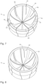
- Fig. 2 shows a schematic view of a blow mold according to the invention.
- This blow mold has two side parts 2, 4 and a base part 6. Together, these two side parts and the base part 6 form a cavity 18 within which the plastic preforms are expanded to form the plastic containers.
- the vent openings described above are located in particular in the base part, but they can also be provided in the side parts, for example in order to be able to better form complicated curvatures of the plastic container.
- the reference numerals 12, 14 refer to carrier shells which carry the side parts 2, 4 and the reference numerals 22, 24 refer to blow mold carriers to which the side parts are each attached (via the carrier shells 12, 14).
- the reference number 60 refers to a vacuum generating device which is only shown schematically. This can be controlled in such a way that it draws air from the interior of the blow mold during a predetermined period of time during the expansion of the plastic preforms.
- Figure 3 shows a schematic representation of a base part 6 according to the invention.
- the base part has five sections 6a, 6b, 6c, 6d, 6e, which each form a standing area or are suitable and intended for forming a standing area of the plastic container 20.
- each stand area a plurality of openings 30 are formed, which are holes here.
- a plurality of openings 30 are formed, which are holes here.
- the Figure 3 a base part 6 with a base diameter of 65 mm with ten holes in each section 6a, 6b, 6c, 6d, 6e, which have a diameter of 1 mm.
- the Figure 4 shows a further schematic representation of a base part 6 according to the invention.
- openings 30 are provided in each section, which consist of a plurality of holes 32.
- each section has 24 holes 32.
- the diameter of the bottom part 6 of the Figure 4 either larger than the diameter of the bottom part of the Figure 3 or the holes here have a smaller diameter than the holes in the Figure 3
- the Figure 4 a base part 6 with a base diameter of 100 mm with 24 holes 32 in each section 6a, 6b, 6c, 6d, 6e, which have a diameter of 1 mm.
- the Figure 5 shows a further schematic representation of a base part 6 according to the invention.
- ten holes 32 are arranged in each section of the base part 6, which, however, have a larger diameter than the holes in the bottom part of the Figure 3 .
- the Figure 5 a base part 6 with a base diameter of 100 mm with ten holes 32 in each section 6a, 6b, 6c, 6d, 6e, which have a diameter of 1.5 mm.
- each section of the base part 6 nine holes 32 are arranged, which have different diameters.
- the Figure 6 a base part 6 with a base diameter of 100 mm with nine holes 32 in each section 6a, 6b, 6c, 6d, 6e, eight holes having a diameter of 1 mm and one hole having a diameter of 4 mm.
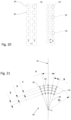
- FIGS 7-9 show further schematic representations of a base part 6 according to the invention.
- openings 30 are arranged in each section 6a, 6b, 6c, 6d, 6e of the base part 6, which are designed here as slots 33.
- a ring is arranged on the base part 6 in addition to improving stability.
- the ring can preferably be arranged on the outer circumference of the base part 6 by shrinking, screwing or welding.
- FIGS. 10-13 show a further embodiment of a base part 6 according to the invention, wherein the openings 30 here consist of a combination of holes 32 or bores and slots 33. It can be seen that holes 32 are arranged at the ends of the slots 33, wherein the slots 33 preferably run from hole 32 to hole 32. In this embodiment, ten holes 32 and two slots 33 are arranged in each section 6a, 6b, 6c, 6d and 6e of the base part 6.
- Figure 14 shows a further schematic representation of a base part 6 according to the invention.
- a plurality of holes are arranged along a row 34 and thus form a type of slot.
- the base part can also have further holes 32.
- the arrangement of the openings 30 in the Figure 14 the arrangement of the openings 30 in the Figure 10 with the difference that the Figure 10 openings designed as slots in the Figure 14 by a plurality of holes arranged along a row 34.
- the reference numerals 6a-6e again identify the individual sections of the base part 6.
- Figure 15 shows a further schematic representation of a base part 6 according to the invention.
- the Figure 15 shows an embodiment in which two rows 34, each with a plurality of holes, are arranged parallel to one another. The arrangement of several such rows would also be conceivable.
- Figure 16 is an exterior view of the Figure 14 shown base part 6. It can be seen that a channel 36 is formed on the outer surface 35 of the base part 6 in the area of the rows 34. The gaseous medium can be discharged from the base part more quickly through this channel.
- the channel 36 is formed with a width that is multiple of the diameter of the holes arranged in the row 34.
- Figure 17 shows a cross-sectional view of the Fig. 14 shown base part 6.
- the plurality of holes arranged in a row 34 can be seen again, as well as the channels 36 arranged on the outer surface 35 of the base part 6, in the area of the rows 34.
- Figure 18 shows a further schematic representation of a base part 6 according to the invention.
- a plurality of holes are arranged along a spline 38.
- This arrangement of the openings 30 corresponds to the arrangement of the openings 30 in the Figure 11 with the difference that the Figure 11 openings formed as curved slots in the Figure 18 by a plurality of holes arranged along a spline 38.
- Figure 19 is an exterior view of the Figure 18 shown base part 6.
- the channel 36 can be seen again, which corresponds in shape to the spline 38 formed by the holes.
- Figure 20 shows a schematic representation of an arrangement of holes 32 in a row 34.
- there are two rows 34 of holes 32 whereby the holes 32 are arranged at the same height and directly next to each other.
- two rows 34 of holes 32 can also be seen, whereby the holes 32 are arranged offset from each other.
- the small arrows indicate the distances between the holes, which can be the same or different.
- Figure 21 shows an example of a drilling pattern 40 of a section of the base part.
- the drilling pattern is perpendicular to a surface of the base geometry of the base and is preferably arranged centrally on the base of the base part with respect to a center point M of the base part.
- the individual holes 32 are arranged here in particular in several columns 44 and rows 42.
- the angles A and B depend on the width of the base.
- the angle A which extends from the center point M to the respective adjacent column, is preferably between 2° and 60°, preferably between 5° and 35° and particularly preferably between 10° and 25°.
- the angle B between two columns arranged next to one another is preferably between 0.5° and 30°, preferably between 0.8° and 25° and particularly preferably between 1° and 20°.
- the angle A can preferably also depend on the diameter of the container or be in a ratio X to the container diameter.
- the ratio X can preferably be between 0 and 10.
- the reference symbol R indicates the radius of the base part and the reference symbols C-E indicate the distances between the holes along a row or column 44.
- the radius R is preferably either in a ratio RD to the container diameter or in a ratio RS to a standing circle diameter of the base.
- the ratio RD can be between 0 and 1, preferably between 0.25 and 0.90.
- the ratio RS can be between 0 and 2, preferably between 0.5 and 1.5.
- Figure 22 shows another example of a drilling pattern 40 of a section of the base part.
- the individual holes 23 are again arranged in several columns 44 and rows 42, whereby the columns 44 are marked with the numbers 20-28 and the rows with the numbers 1-10.
- the columns 44 are preferably arranged in a radial direction to a center point M of the base part and the rows 42 in the circumferential direction of the base part.
- the individual holes 32 within a drilling pattern 40 can preferably have the same diameter or a different diameter. If the holes 32 are of different sizes, they are preferably in a ratio BD to one another which is between 0.25 and 10, preferably between 0.5 and 6.
- the Figures 23-26 show further exemplary drilling patterns 40 of a section of the base part.
- a large number of holes 32 are arranged in several columns 44 and rows 42.
- the respective drilling pattern 40 can consist of any number of holes 32, which have either the same or different diameters.
Landscapes
- Engineering & Computer Science (AREA)
- Manufacturing & Machinery (AREA)
- Mechanical Engineering (AREA)
- Moulds For Moulding Plastics Or The Like (AREA)
- Containers Having Bodies Formed In One Piece (AREA)
- Blow-Moulding Or Thermoforming Of Plastics Or The Like (AREA)
Claims (9)
- Moule de soufflage (1) pour la formation de préformes en matière plastique (10) en récipients en matière plastique (20) avec au moins deux parties latérales de moule de soufflage (2, 4) et une partie de fond (6) qui réalisent une cavité (18), à l'intérieur de laquelle des préformes en matière plastique (10) sont formables par alimentation en un milieu coulant en récipients en matière plastique (20), dans lequel une paroi intérieure délimitant la cavité (18) des parties latérales de moule de soufflage (2, 4) et de la partie de fond (6) présente un contour qui génère une forme prédéfinie des récipients en matière plastique (20) à fabriquer, dans lequel une pluralité d'ouvertures (30) est prévue dans au moins une section (6a, 6b, 6c, 6d) de la partie de fond (6), lesquelles permettent une évacuation d'un milieu gazeux pendant un processus d'expansion du récipient en matière plastique,
caractérisé en ce que
un rapport entre une surface de la partie de fond (6) et une surface des ouvertures (30) se situe entre 35 et 175 et le rapport dépend d'une grandeur du récipient en matière plastique et d'une forme des ouvertures. - Moule de soufflage (1) selon la revendication 1,
caractérisé en ce que
un diamètre de la partie de fond (6) se situe entre 50 mm et 200 mm et la surface des ouvertures (30) entre 23 mm2 et 500 mm2. - Moule de soufflage (1) selon la revendication 1,
caractérisé en ce que
la surface de la partie de fond (6) se situe entre 3900 mm2 et 65 000 mm2 et la surface des ouvertures (30) entre 23 mm2 et 500 mm2. - Moule de soufflage (1) selon la revendication 1,
caractérisé en ce que
il s'agit pour les ouvertures (30) d'une pluralité de trous (32) et/ou de fentes (33) qui est agencée dans la partie de fond (6). - Moule de soufflage (1) selon la revendication 1,
caractérisé en ce que
la partie de fond (6) est réalisée pour la réalisation de pieds d'appui du récipient en matière plastique (20), dans lequel chaque pied d'appui présente une pluralité d'ouvertures (30). - Moule de soufflage (1) selon la revendication 5,
caractérisé en ce que
chaque pied d'appui présente 7 à 35 ouvertures (30), de préférence 8 à 30 ouvertures (30) et de manière particulièrement préférée 10 à 25 ouvertures (30). - Moule de soufflage (1) selon la revendication 4,
caractérisé en ce que
au moins un trou (32) présente un diamètre qui se situe entre 0,5 mm et 4 mm, de préférence entre 0,8 mm et 2 mm. - Moule de soufflage (1) selon la revendication 4,
caractérisé en ce que
au moins une fente (33) présente une largeur qui se situe entre 0,4 mm et 2 mm, de préférence entre 0,5 mm et 1 mm et de manière particulièrement préférée entre 0,6 mm et 0,8 mm. - Partie de fond (6) pour un moule de soufflage (1) pour la formation de préformes en matière plastique en récipients en matière plastique (20) selon les revendications 1 à 8, dans laquelle la partie de fond (6) présente une paroi intérieure avec un contour qui génère une forme de fond prédéfinie des récipients en matière plastique (20) à fabriquer, dans laquelle une pluralité d'ouvertures (30) est prévue dans au moins une section (6a, 6b, 6c, 6d) de la partie de fond (6), lesquelles permettent une évacuation d'un milieu gazeux pendant un processus d'expansion du récipient en matière plastique (20),
caractérisée en ce que
un rapport entre une surface de la partie de fond (6) et une surface des ouvertures (30) se situe entre 35 et 175 et le rapport dépend d'une grandeur du récipient en matière plastique et d'une forme des ouvertures.
Applications Claiming Priority (1)
| Application Number | Priority Date | Filing Date | Title |
|---|---|---|---|
| DE102021134057.8A DE102021134057A1 (de) | 2021-12-21 | 2021-12-21 | Blasform zum Umformen von Kunststoffvorformlingen zu Kunststoffbehältnissen mit Luftabführung sowie Bodenteil für eine Blasform |
Publications (2)
| Publication Number | Publication Date |
|---|---|
| EP4201638A1 EP4201638A1 (fr) | 2023-06-28 |
| EP4201638B1 true EP4201638B1 (fr) | 2024-11-06 |
Family
ID=80999146
Family Applications (1)
| Application Number | Title | Priority Date | Filing Date |
|---|---|---|---|
| EP22165267.0A Active EP4201638B1 (fr) | 2021-12-21 | 2022-03-29 | Moule de soufflage permettant de former des préformes en matière plastique pour obtenir des récipients en matière plastique pourvus de sortie d'air, ainsi que partie de fond pour un moule de soufflage |
Country Status (4)
| Country | Link |
|---|---|
| US (1) | US11833732B2 (fr) |
| EP (1) | EP4201638B1 (fr) |
| CN (1) | CN218139815U (fr) |
| DE (1) | DE102021134057A1 (fr) |
Families Citing this family (1)
| Publication number | Priority date | Publication date | Assignee | Title |
|---|---|---|---|---|
| DE102024120719A1 (de) * | 2024-07-22 | 2026-01-22 | Krones Aktiengesellschaft | Bodenform zum Umformen von Kunststoffvorformlingen zu Kunststoffbehältnissen mit Luftabführung sowie Blasform |
Family Cites Families (8)
| Publication number | Priority date | Publication date | Assignee | Title |
|---|---|---|---|---|
| FR2892048B1 (fr) * | 2005-10-17 | 2008-01-04 | Sidel Sas | Fond de moule pour moule de fabrication de recipients thermoplastiques, et dispositif de moulage equipe d'au moins un moule equipe d'un tel fond. |
| DE102013109716A1 (de) * | 2013-09-05 | 2015-03-05 | Krones Ag | Blasform, Blasformmaschine und Verfahren zur Umformung von Kunststoffvorformlingen zu Kunststoffbehältnissen mit Luftabführung |
| FR3015342B1 (fr) * | 2013-12-19 | 2016-02-05 | Sidel Participations | Dispositif de moulage comprenant un fond de moule monobloc incluant une cavite d'echange thermique epousant une surface de moulage |
| FR3015344B1 (fr) | 2013-12-19 | 2016-05-27 | Sidel Participations | Element de moule pour le formage de recipient, pourvu d'events de decompression sous forme de fentes |
| DE102013226906A1 (de) | 2013-12-20 | 2015-07-09 | P & L Gmbh & Co. Kg | Mehrteilige Blasform für die Herstellung von geblasenen, aus Kunststoff bestehenden Werkstücken, sowie Verfahren zu deren Herstellung |
| RU2707519C2 (ru) * | 2015-02-25 | 2019-11-27 | С.И.П.А. Сосьета' Индустриалидзационе Проджеттационе Э Аутомационе С.П.А. | Выдувная пресс-форма для изготовления емкостей из термопластичного материала |
| FR3045445B1 (fr) * | 2015-12-16 | 2018-06-15 | Sidel Participations | Fond de moule a larges events pour le formage d'un recipient |
| DE102018123624A1 (de) * | 2018-09-25 | 2020-03-26 | Krones Ag | Vorrichtung zum Umformen von Kunststoffvorformlingen zu Kunststoffbehältnissen sowie eine Blasform und ein Verfahren zur Herstellung eines Behältnisses |
-
2021
- 2021-12-21 DE DE102021134057.8A patent/DE102021134057A1/de active Pending
-
2022
- 2022-03-29 EP EP22165267.0A patent/EP4201638B1/fr active Active
- 2022-03-29 US US17/707,747 patent/US11833732B2/en active Active
- 2022-04-08 CN CN202220813575.5U patent/CN218139815U/zh active Active
Also Published As
| Publication number | Publication date |
|---|---|
| CN218139815U (zh) | 2022-12-27 |
| US11833732B2 (en) | 2023-12-05 |
| EP4201638A1 (fr) | 2023-06-28 |
| US20230191687A1 (en) | 2023-06-22 |
| DE102021134057A1 (de) | 2023-06-22 |
Similar Documents
| Publication | Publication Date | Title |
|---|---|---|
| EP2986517B1 (fr) | Récipient de boisson en matière synthétique et moule de soufflage pour sa fabrication | |
| EP3272498B1 (fr) | Moule de soufflage, machine de formage par soufflage et procédé de transformation de de préformes en matière plastique en récipients en matière plastique dotés d'une évacuation d'air | |
| EP3458370B1 (fr) | Bouteille en matière plastique munie de bandes de tension en intersection | |
| EP4201638B1 (fr) | Moule de soufflage permettant de former des préformes en matière plastique pour obtenir des récipients en matière plastique pourvus de sortie d'air, ainsi que partie de fond pour un moule de soufflage | |
| DE3316757A1 (de) | Maschine zum herstellen von hohlkoerpern durch strecken und blasformen | |
| DE2700475C2 (de) | Matrizen-Anordnung zur Zieh- oder Preßformung von Napf- oder Becherformen aus Blechronden | |
| EP2085207A2 (fr) | Dispositif de fabrication de lamelles de soufflage | |
| DE102010032618A1 (de) | Blasformwerkzeug | |
| DE102013226906A1 (de) | Mehrteilige Blasform für die Herstellung von geblasenen, aus Kunststoff bestehenden Werkstücken, sowie Verfahren zu deren Herstellung | |
| DE2210099C3 (de) | Verfahren und Vorrichtung zur Ausformung von Gegenständen aus wärmehärtenden Werkstoffen, insbesondere von Fahrzeugluftreifen | |
| DE19628166C2 (de) | Verfahren zur Herstellung eines Stiftes zum Entlüften von Formmulden bei der Ausformung und/oder Vulkanisation von Gummiartikeln | |
| DE20115180U1 (de) | Werkzeugkopf zur Extrusion eines rohrförmigen Stranges aus mindestens einer thermoplastischen Kunststoffschmelze für die Herstellung von Blasfolien | |
| EP1964660B1 (fr) | Anneau pour moule de soufflage avec dispositif de centrage pour la préforme | |
| EP3793804B1 (fr) | Dispositif pour mouler des ébauches en matière plastique en récipients en matière plastique et moule de soufflage et procédé pour réaliser des récipients | |
| DE102024120719A1 (de) | Bodenform zum Umformen von Kunststoffvorformlingen zu Kunststoffbehältnissen mit Luftabführung sowie Blasform | |
| EP3995285B1 (fr) | Machine à mouler par soufflage pourvue de moule de fond thermorégulé | |
| DE102013005080B4 (de) | Formwerkzeug zum Warmumformen und/oder Presshärten eines Blechmaterials, sowie Verfahren zum Herstellen eines kühlbaren Formwerkzeugsegments | |
| DE2208909A1 (de) | Blas- und fuelldorn | |
| DE102018131396A1 (de) | Aseptische Blasformmaschine mit Entlüftungskanal | |
| EP1996385B1 (fr) | Poste de soufflage pour machine de soufflage-etirage | |
| DE69229058T2 (de) | Verfahren zum blasformen von rohrfoermigen behaeltern | |
| EP3388682A1 (fr) | Corps de refroidissement pour une pompe à vide et son procédé de fabrication | |
| DE102006011021A1 (de) | Verfahren und Vorrichtung zur Herstellung eines eine Nabe aufweisenden Formkörpers | |
| DE102023102122A1 (de) | Kunststoffbehälter, Formwerkzeug, Vorrichtung umfassend das Formwerkzeug und Verfahren zum Herstellen und Befüllen eines Kunststoffbehälters | |
| DE102021114558A1 (de) | Vorformling aus thermoplastischem Material zur Herstellung eines Behälters |
Legal Events
| Date | Code | Title | Description |
|---|---|---|---|
| PUAI | Public reference made under article 153(3) epc to a published international application that has entered the european phase |
Free format text: ORIGINAL CODE: 0009012 |
|
| STAA | Information on the status of an ep patent application or granted ep patent |
Free format text: STATUS: THE APPLICATION HAS BEEN PUBLISHED |
|
| AK | Designated contracting states |
Kind code of ref document: A1 Designated state(s): AL AT BE BG CH CY CZ DE DK EE ES FI FR GB GR HR HU IE IS IT LI LT LU LV MC MK MT NL NO PL PT RO RS SE SI SK SM TR |
|
| STAA | Information on the status of an ep patent application or granted ep patent |
Free format text: STATUS: REQUEST FOR EXAMINATION WAS MADE |
|
| 17P | Request for examination filed |
Effective date: 20231130 |
|
| RBV | Designated contracting states (corrected) |
Designated state(s): AL AT BE BG CH CY CZ DE DK EE ES FI FR GB GR HR HU IE IS IT LI LT LU LV MC MK MT NL NO PL PT RO RS SE SI SK SM TR |
|
| GRAP | Despatch of communication of intention to grant a patent |
Free format text: ORIGINAL CODE: EPIDOSNIGR1 |
|
| STAA | Information on the status of an ep patent application or granted ep patent |
Free format text: STATUS: GRANT OF PATENT IS INTENDED |
|
| RIC1 | Information provided on ipc code assigned before grant |
Ipc: B29L 31/00 20060101ALN20240430BHEP Ipc: B29K 67/00 20060101ALN20240430BHEP Ipc: B29C 49/06 20060101ALN20240430BHEP Ipc: B29C 49/62 20060101ALI20240430BHEP Ipc: B29C 49/48 20060101AFI20240430BHEP |
|
| INTG | Intention to grant announced |
Effective date: 20240528 |
|
| GRAS | Grant fee paid |
Free format text: ORIGINAL CODE: EPIDOSNIGR3 |
|
| GRAA | (expected) grant |
Free format text: ORIGINAL CODE: 0009210 |
|
| STAA | Information on the status of an ep patent application or granted ep patent |
Free format text: STATUS: THE PATENT HAS BEEN GRANTED |
|
| AK | Designated contracting states |
Kind code of ref document: B1 Designated state(s): AL AT BE BG CH CY CZ DE DK EE ES FI FR GB GR HR HU IE IS IT LI LT LU LV MC MK MT NL NO PL PT RO RS SE SI SK SM TR |
|
| REG | Reference to a national code |
Ref country code: GB Ref legal event code: FG4D Free format text: NOT ENGLISH |
|
| REG | Reference to a national code |
Ref country code: CH Ref legal event code: EP |
|
| REG | Reference to a national code |
Ref country code: DE Ref legal event code: R096 Ref document number: 502022002048 Country of ref document: DE |
|
| REG | Reference to a national code |
Ref country code: IE Ref legal event code: FG4D Free format text: LANGUAGE OF EP DOCUMENT: GERMAN |
|
| P01 | Opt-out of the competence of the unified patent court (upc) registered |
Free format text: CASE NUMBER: APP_1783/2025 Effective date: 20250110 |
|
| REG | Reference to a national code |
Ref country code: LT Ref legal event code: MG9D |
|
| REG | Reference to a national code |
Ref country code: NL Ref legal event code: MP Effective date: 20241106 |
|
| PG25 | Lapsed in a contracting state [announced via postgrant information from national office to epo] |
Ref country code: IS Free format text: LAPSE BECAUSE OF FAILURE TO SUBMIT A TRANSLATION OF THE DESCRIPTION OR TO PAY THE FEE WITHIN THE PRESCRIBED TIME-LIMIT Effective date: 20250306 Ref country code: HR Free format text: LAPSE BECAUSE OF FAILURE TO SUBMIT A TRANSLATION OF THE DESCRIPTION OR TO PAY THE FEE WITHIN THE PRESCRIBED TIME-LIMIT Effective date: 20241106 Ref country code: PT Free format text: LAPSE BECAUSE OF FAILURE TO SUBMIT A TRANSLATION OF THE DESCRIPTION OR TO PAY THE FEE WITHIN THE PRESCRIBED TIME-LIMIT Effective date: 20250306 |
|
| PGFP | Annual fee paid to national office [announced via postgrant information from national office to epo] |
Ref country code: DE Payment date: 20250204 Year of fee payment: 4 |
|
| PG25 | Lapsed in a contracting state [announced via postgrant information from national office to epo] |
Ref country code: FI Free format text: LAPSE BECAUSE OF FAILURE TO SUBMIT A TRANSLATION OF THE DESCRIPTION OR TO PAY THE FEE WITHIN THE PRESCRIBED TIME-LIMIT Effective date: 20241106 Ref country code: NL Free format text: LAPSE BECAUSE OF FAILURE TO SUBMIT A TRANSLATION OF THE DESCRIPTION OR TO PAY THE FEE WITHIN THE PRESCRIBED TIME-LIMIT Effective date: 20241106 |
|
| PG25 | Lapsed in a contracting state [announced via postgrant information from national office to epo] |
Ref country code: BG Free format text: LAPSE BECAUSE OF FAILURE TO SUBMIT A TRANSLATION OF THE DESCRIPTION OR TO PAY THE FEE WITHIN THE PRESCRIBED TIME-LIMIT Effective date: 20241106 |
|
| PG25 | Lapsed in a contracting state [announced via postgrant information from national office to epo] |
Ref country code: ES Free format text: LAPSE BECAUSE OF FAILURE TO SUBMIT A TRANSLATION OF THE DESCRIPTION OR TO PAY THE FEE WITHIN THE PRESCRIBED TIME-LIMIT Effective date: 20241106 |
|
| PG25 | Lapsed in a contracting state [announced via postgrant information from national office to epo] |
Ref country code: NO Free format text: LAPSE BECAUSE OF FAILURE TO SUBMIT A TRANSLATION OF THE DESCRIPTION OR TO PAY THE FEE WITHIN THE PRESCRIBED TIME-LIMIT Effective date: 20250206 |
|
| PG25 | Lapsed in a contracting state [announced via postgrant information from national office to epo] |
Ref country code: GR Free format text: LAPSE BECAUSE OF FAILURE TO SUBMIT A TRANSLATION OF THE DESCRIPTION OR TO PAY THE FEE WITHIN THE PRESCRIBED TIME-LIMIT Effective date: 20250207 Ref country code: LV Free format text: LAPSE BECAUSE OF FAILURE TO SUBMIT A TRANSLATION OF THE DESCRIPTION OR TO PAY THE FEE WITHIN THE PRESCRIBED TIME-LIMIT Effective date: 20241106 |
|
| PGFP | Annual fee paid to national office [announced via postgrant information from national office to epo] |
Ref country code: AT Payment date: 20250417 Year of fee payment: 4 |
|
| PG25 | Lapsed in a contracting state [announced via postgrant information from national office to epo] |
Ref country code: PL Free format text: LAPSE BECAUSE OF FAILURE TO SUBMIT A TRANSLATION OF THE DESCRIPTION OR TO PAY THE FEE WITHIN THE PRESCRIBED TIME-LIMIT Effective date: 20241106 |
|
| PGFP | Annual fee paid to national office [announced via postgrant information from national office to epo] |
Ref country code: FR Payment date: 20250210 Year of fee payment: 4 |
|
| PG25 | Lapsed in a contracting state [announced via postgrant information from national office to epo] |
Ref country code: RS Free format text: LAPSE BECAUSE OF FAILURE TO SUBMIT A TRANSLATION OF THE DESCRIPTION OR TO PAY THE FEE WITHIN THE PRESCRIBED TIME-LIMIT Effective date: 20250206 |
|
| PG25 | Lapsed in a contracting state [announced via postgrant information from national office to epo] |
Ref country code: SM Free format text: LAPSE BECAUSE OF FAILURE TO SUBMIT A TRANSLATION OF THE DESCRIPTION OR TO PAY THE FEE WITHIN THE PRESCRIBED TIME-LIMIT Effective date: 20241106 |
|
| PG25 | Lapsed in a contracting state [announced via postgrant information from national office to epo] |
Ref country code: DK Free format text: LAPSE BECAUSE OF FAILURE TO SUBMIT A TRANSLATION OF THE DESCRIPTION OR TO PAY THE FEE WITHIN THE PRESCRIBED TIME-LIMIT Effective date: 20241106 |
|
| PGFP | Annual fee paid to national office [announced via postgrant information from national office to epo] |
Ref country code: IT Payment date: 20250331 Year of fee payment: 4 |
|
| PG25 | Lapsed in a contracting state [announced via postgrant information from national office to epo] |
Ref country code: EE Free format text: LAPSE BECAUSE OF FAILURE TO SUBMIT A TRANSLATION OF THE DESCRIPTION OR TO PAY THE FEE WITHIN THE PRESCRIBED TIME-LIMIT Effective date: 20241106 |
|
| PG25 | Lapsed in a contracting state [announced via postgrant information from national office to epo] |
Ref country code: RO Free format text: LAPSE BECAUSE OF FAILURE TO SUBMIT A TRANSLATION OF THE DESCRIPTION OR TO PAY THE FEE WITHIN THE PRESCRIBED TIME-LIMIT Effective date: 20241106 |
|
| PG25 | Lapsed in a contracting state [announced via postgrant information from national office to epo] |
Ref country code: SK Free format text: LAPSE BECAUSE OF FAILURE TO SUBMIT A TRANSLATION OF THE DESCRIPTION OR TO PAY THE FEE WITHIN THE PRESCRIBED TIME-LIMIT Effective date: 20241106 |
|
| PG25 | Lapsed in a contracting state [announced via postgrant information from national office to epo] |
Ref country code: CZ Free format text: LAPSE BECAUSE OF FAILURE TO SUBMIT A TRANSLATION OF THE DESCRIPTION OR TO PAY THE FEE WITHIN THE PRESCRIBED TIME-LIMIT Effective date: 20241106 |
|
| REG | Reference to a national code |
Ref country code: DE Ref legal event code: R097 Ref document number: 502022002048 Country of ref document: DE |
|
| PG25 | Lapsed in a contracting state [announced via postgrant information from national office to epo] |
Ref country code: SE Free format text: LAPSE BECAUSE OF FAILURE TO SUBMIT A TRANSLATION OF THE DESCRIPTION OR TO PAY THE FEE WITHIN THE PRESCRIBED TIME-LIMIT Effective date: 20241106 |
|
| PLBE | No opposition filed within time limit |
Free format text: ORIGINAL CODE: 0009261 |
|
| STAA | Information on the status of an ep patent application or granted ep patent |
Free format text: STATUS: NO OPPOSITION FILED WITHIN TIME LIMIT |
|
| PG25 | Lapsed in a contracting state [announced via postgrant information from national office to epo] |
Ref country code: MC Free format text: LAPSE BECAUSE OF FAILURE TO SUBMIT A TRANSLATION OF THE DESCRIPTION OR TO PAY THE FEE WITHIN THE PRESCRIBED TIME-LIMIT Effective date: 20241106 |
|
| 26N | No opposition filed |
Effective date: 20250807 |
|
| REG | Reference to a national code |
Ref country code: CH Ref legal event code: H13 Free format text: ST27 STATUS EVENT CODE: U-0-0-H10-H13 (AS PROVIDED BY THE NATIONAL OFFICE) Effective date: 20251023 |
|
| PG25 | Lapsed in a contracting state [announced via postgrant information from national office to epo] |
Ref country code: LU Free format text: LAPSE BECAUSE OF NON-PAYMENT OF DUE FEES Effective date: 20250329 |
|
| REG | Reference to a national code |
Ref country code: BE Ref legal event code: MM Effective date: 20250331 |
|
| PG25 | Lapsed in a contracting state [announced via postgrant information from national office to epo] |
Ref country code: BE Free format text: LAPSE BECAUSE OF NON-PAYMENT OF DUE FEES Effective date: 20250331 |
|
| PG25 | Lapsed in a contracting state [announced via postgrant information from national office to epo] |
Ref country code: CH Free format text: LAPSE BECAUSE OF NON-PAYMENT OF DUE FEES Effective date: 20250331 |
|
| PG25 | Lapsed in a contracting state [announced via postgrant information from national office to epo] |
Ref country code: IE Free format text: LAPSE BECAUSE OF NON-PAYMENT OF DUE FEES Effective date: 20250329 |