EP1996385B1 - Blasstation für streckblasmaschinen - Google Patents
Blasstation für streckblasmaschinen Download PDFInfo
- Publication number
- EP1996385B1 EP1996385B1 EP06705402A EP06705402A EP1996385B1 EP 1996385 B1 EP1996385 B1 EP 1996385B1 EP 06705402 A EP06705402 A EP 06705402A EP 06705402 A EP06705402 A EP 06705402A EP 1996385 B1 EP1996385 B1 EP 1996385B1
- Authority
- EP
- European Patent Office
- Prior art keywords
- blow
- cylinder
- axis
- valves
- blowing
- Prior art date
- Legal status (The legal status is an assumption and is not a legal conclusion. Google has not performed a legal analysis and makes no representation as to the accuracy of the status listed.)
- Not-in-force
Links
- 238000000071 blow moulding Methods 0.000 title claims abstract description 32
- 230000003584 silencer Effects 0.000 claims description 7
- 230000005611 electricity Effects 0.000 claims description 5
- 238000000465 moulding Methods 0.000 claims description 5
- 238000007664 blowing Methods 0.000 abstract description 75
- 230000001276 controlling effect Effects 0.000 abstract description 5
- 230000001105 regulatory effect Effects 0.000 abstract description 3
- -1 polyethylene terephthalate Polymers 0.000 abstract 2
- 229920000139 polyethylene terephthalate Polymers 0.000 abstract 2
- 239000005020 polyethylene terephthalate Substances 0.000 abstract 2
- 238000006073 displacement reaction Methods 0.000 abstract 1
- 238000000034 method Methods 0.000 description 13
- 238000012423 maintenance Methods 0.000 description 8
- 238000013461 design Methods 0.000 description 3
- 238000004519 manufacturing process Methods 0.000 description 3
- 230000008439 repair process Effects 0.000 description 2
- 238000010924 continuous production Methods 0.000 description 1
- 239000000498 cooling water Substances 0.000 description 1
- 230000010354 integration Effects 0.000 description 1
- 230000008092 positive effect Effects 0.000 description 1
- 238000012545 processing Methods 0.000 description 1
- 238000013022 venting Methods 0.000 description 1
Images

Classifications
-
- B—PERFORMING OPERATIONS; TRANSPORTING
- B29—WORKING OF PLASTICS; WORKING OF SUBSTANCES IN A PLASTIC STATE IN GENERAL
- B29C—SHAPING OR JOINING OF PLASTICS; SHAPING OF MATERIAL IN A PLASTIC STATE, NOT OTHERWISE PROVIDED FOR; AFTER-TREATMENT OF THE SHAPED PRODUCTS, e.g. REPAIRING
- B29C49/00—Blow-moulding, i.e. blowing a preform or parison to a desired shape within a mould; Apparatus therefor
- B29C49/28—Blow-moulding apparatus
- B29C49/30—Blow-moulding apparatus having movable moulds or mould parts
- B29C49/36—Blow-moulding apparatus having movable moulds or mould parts rotatable about one axis
-
- B—PERFORMING OPERATIONS; TRANSPORTING
- B29—WORKING OF PLASTICS; WORKING OF SUBSTANCES IN A PLASTIC STATE IN GENERAL
- B29C—SHAPING OR JOINING OF PLASTICS; SHAPING OF MATERIAL IN A PLASTIC STATE, NOT OTHERWISE PROVIDED FOR; AFTER-TREATMENT OF THE SHAPED PRODUCTS, e.g. REPAIRING
- B29C49/00—Blow-moulding, i.e. blowing a preform or parison to a desired shape within a mould; Apparatus therefor
- B29C49/42—Component parts, details or accessories; Auxiliary operations
- B29C49/78—Measuring, controlling or regulating
- B29C49/783—Measuring, controlling or regulating blowing pressure
- B29C2049/7831—Measuring, controlling or regulating blowing pressure characterised by pressure values or ranges
-
- B—PERFORMING OPERATIONS; TRANSPORTING
- B29—WORKING OF PLASTICS; WORKING OF SUBSTANCES IN A PLASTIC STATE IN GENERAL
- B29C—SHAPING OR JOINING OF PLASTICS; SHAPING OF MATERIAL IN A PLASTIC STATE, NOT OTHERWISE PROVIDED FOR; AFTER-TREATMENT OF THE SHAPED PRODUCTS, e.g. REPAIRING
- B29C49/00—Blow-moulding, i.e. blowing a preform or parison to a desired shape within a mould; Apparatus therefor
- B29C49/42—Component parts, details or accessories; Auxiliary operations
- B29C49/78—Measuring, controlling or regulating
- B29C49/783—Measuring, controlling or regulating blowing pressure
- B29C2049/7832—Blowing with two or more pressure levels
-
- B—PERFORMING OPERATIONS; TRANSPORTING
- B29—WORKING OF PLASTICS; WORKING OF SUBSTANCES IN A PLASTIC STATE IN GENERAL
- B29C—SHAPING OR JOINING OF PLASTICS; SHAPING OF MATERIAL IN A PLASTIC STATE, NOT OTHERWISE PROVIDED FOR; AFTER-TREATMENT OF THE SHAPED PRODUCTS, e.g. REPAIRING
- B29C2949/00—Indexing scheme relating to blow-moulding
- B29C2949/07—Preforms or parisons characterised by their configuration
- B29C2949/0715—Preforms or parisons characterised by their configuration the preform having one end closed
-
- B—PERFORMING OPERATIONS; TRANSPORTING
- B29—WORKING OF PLASTICS; WORKING OF SUBSTANCES IN A PLASTIC STATE IN GENERAL
- B29C—SHAPING OR JOINING OF PLASTICS; SHAPING OF MATERIAL IN A PLASTIC STATE, NOT OTHERWISE PROVIDED FOR; AFTER-TREATMENT OF THE SHAPED PRODUCTS, e.g. REPAIRING
- B29C49/00—Blow-moulding, i.e. blowing a preform or parison to a desired shape within a mould; Apparatus therefor
- B29C49/02—Combined blow-moulding and manufacture of the preform or the parison
- B29C49/06—Injection blow-moulding
-
- B—PERFORMING OPERATIONS; TRANSPORTING
- B29—WORKING OF PLASTICS; WORKING OF SUBSTANCES IN A PLASTIC STATE IN GENERAL
- B29C—SHAPING OR JOINING OF PLASTICS; SHAPING OF MATERIAL IN A PLASTIC STATE, NOT OTHERWISE PROVIDED FOR; AFTER-TREATMENT OF THE SHAPED PRODUCTS, e.g. REPAIRING
- B29C49/00—Blow-moulding, i.e. blowing a preform or parison to a desired shape within a mould; Apparatus therefor
- B29C49/42—Component parts, details or accessories; Auxiliary operations
- B29C49/4289—Valve constructions or configurations, e.g. arranged to reduce blowing fluid consumption
-
- B—PERFORMING OPERATIONS; TRANSPORTING
- B29—WORKING OF PLASTICS; WORKING OF SUBSTANCES IN A PLASTIC STATE IN GENERAL
- B29C—SHAPING OR JOINING OF PLASTICS; SHAPING OF MATERIAL IN A PLASTIC STATE, NOT OTHERWISE PROVIDED FOR; AFTER-TREATMENT OF THE SHAPED PRODUCTS, e.g. REPAIRING
- B29C49/00—Blow-moulding, i.e. blowing a preform or parison to a desired shape within a mould; Apparatus therefor
- B29C49/42—Component parts, details or accessories; Auxiliary operations
- B29C49/58—Blowing means
Definitions
- the present invention relates to a blowing station for stretch blow molding machine according to the preamble of claim 1 and a stretch blow molding machine according to the preamble of claim 11, as in the document DE-U-20018500 is disclosed.
- the molded body is advantageously constructed at least two parts, in which the bottle blank is introduced in the open state and from which after the blowing process the finished blown bottle is removed. In this case, the bottle blank is held over his already finished shape having bottle head resp. fixed.
- a blowing cylinder which is displaceable relative to the shaped body is furthermore arranged in such a way that it can be brought into abutment against the respective bottle head.
- the blowing process is advantageously carried out in two stages, with a first so-called Vorblastress in which compressed air is injected, for example, with a pressure between 4 and 20 bar in the bottle blank and a subsequent actual Blastress, in which, for example, pressure values between 10 to 45 bar are used.
- valves which respectively for controlling the compressed air flow to the blowing cylinder. serve to drain or return the compressed air after the blowing process.
- three valves are generally used, which in turn of control resp. Pilot valves are controlled.
- a plurality of such blow molding stations are arranged concentrically around a central axis of the stretch blow molding machine.
- the blowing stations are driven in rotation about this central axis to allow a continuous, continuous production process.
- the arrangement of the valves and supply resp. Discharges at the blowing station should be chosen such that the greatest possible accessibility to the molding of the blowing cylinder is ensured to the To be able to supply bottle blanks easily and reliably resp. also be able to remove the finished blown bottles from the molded body. Furthermore, all functional components of the blowing station should be easily accessible for maintenance and maintenance work, so that only short production interruptions have to be accepted. For a high production rate, these processes must of course be automated.
- the object of the present invention was to find a blowing station for stretch blow molding machines, which has a space-saving design with optimal accessibility to the individual components.
- a blowing station for a stretch blow molding machine with a central vertical axis of rotation and arranged in the rotation axis rotary distributor for compressed air and electricity, each with at least one shaped body for receiving bottle blanks, a relative to the mold body slidably arranged blowing cylinder, arranged on the blow cylinder valves for regulating the supply and discharge of compressed air and connections for lines for connecting the blowing cylinder to the rotary distributor.
- Blaszylinder arranged parallel to the axis of rotation of the stretch blow molder along its longitudinal axis displaceable vertically above the molding in the blowing station. Further, the valves are arranged in a single blowing block which is arranged at the side of the blowing cylinder at the blowing station.
- valves in a single blower block, which is arranged laterally on the blow cylinder, the space required for the valves is very small.
- the valves themselves are also advantageously arranged vertically one above the other, parallel to the longitudinal axis of the blowing cylinder in the blowing block and thus have very short connecting channels with each other and with the blowing cylinder.
- Another advantage is the fact that the supply lines from the centrally arranged rotary distributor can be realized with only very short lines in the radial direction from the axis of rotation directly into the blowing block.
- control resp. Pilot valves arranged for controlling the valves, wherein these are preferably arranged in each case one above the other parallel to the longitudinal axis of the blowing block facing the front side together.
- control resp. Pilot valves easily accessible from the outside, what the maintenance and maintenance of this control resp. Much easier pilot valves.
- service interruptions in the case of maintenance or repairs can be advantageously limited to a minimum short period of time.
- connections for lines from the rotary distributor are each arranged on the rear side of the blower block.
- very short line paths can thus be realized, which on the one hand shortens the reaction and processing speed and reduces the pressure loss over the short line lengths.
- a blow-off valve is arranged aligned parallel to the axis of rotation at the top of the blower block.
- the valve for deriving the consumed for the blowing process compressed air from the blowing cylinder can thus be arranged in the same blower block at the same time the valve for deriving the consumed for the blowing process compressed air from the blowing cylinder.
- a silencer is arranged axially above the blow-off valve. About this muffler to be discharged to the environment residual pressure is blown while the noise emission is kept within limits.
- the silencer has a blow-out channel with a discharge direction extending substantially parallel to the longitudinal axis of the blow cylinder.
- the exhaust air in ducts is guided approximately parallel to the longitudinal axis in the muffler.
- no additional space in the radial direction with respect to the longitudinal axis is required for the exhaust air, which has a very positive effect on the space requirements, ie in particular the required floor plan area of the blowing station. Due to the small footprint, the floor plan of a stretch blow molding machine equipped with such blowing stations can advantageously be made very small and therefore compact.
- the silencer has a blow-out channel with a discharge direction extending substantially perpendicular to the longitudinal axis of the blow cylinder, preferably extending perpendicularly from the rear side of the blowing station to the outside. If the available space in the vertical direction is limited or should not be exploited, the exhaust air can also be returned radially in the direction of the axis of rotation of the stretch blow molding machine and possibly combined there in a common channel and discharged together upwards.
- a control valve for controlling the shift resp. Lifting movement of the blowing cylinder also arranged laterally on the blow cylinder, preferably on the opposite side of the blowing block of the blowing cylinder.
- a 5/2-way control valve is advantageously used, the control lines are also preferably connected radially inwardly extending directly to the rotary distributor.
- all controls and functional elements are arranged in a common housing, which is arranged on the blow cylinder, preferably one Cylinder carrier.
- a common housing which is arranged on the blow cylinder, preferably one Cylinder carrier.
- a stretch blow molding machine having a central vertical axis of rotation and arranged in the region of the rotation axis rotary distributor for compressed air and electricity, wherein blowing stations are arranged according to one of claims 1 to 10 radially about the axis of rotation, wherein the outside of the blowing stations are arranged radially facing away from the axis of rotation to the outside.
- the individual blow molding stations can advantageously be mounted on stators distributed regularly in the circumferential direction at radially equal distances from the axis of rotation.
- the blowing stations can be operated around the axis of rotation circumferentially and a continuous operation over a long period of operation can be realized.
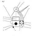
- FIG. 1 is shown purely schematically the plan view of an inventive blowing station of a stretch blow molding machine.
- the rotary distributor 2 is arranged concentrically, resp. executed.
- the rotary distributor 2 may be, for example, a motor-driven, rotating about the axis of rotation 1 blowing wheel.
- a blowing station 3 is arranged radially spaced from the axis of rotation 1, with a machine stand 12 which is arranged parallel to the vertical axis 1. At this Machine stand 12, the components of the blowing station 3 are arranged.
- the blowing cylinder 5 is arranged in a rectangular cross-section cylinder support 13 along its longitudinal axis A slidably. In this way, the blowing cylinder 5 can be moved parallel to the longitudinal axis A and thus also parallel to the axis of rotation 1 of the stretch blow molding machine in accordance with the direction indicated by the arrow H.
- the blowing block 7 is advantageously arranged to the right of the blowing cylinder 5, for example by attachment to the cylinder support 13.
- the valves necessary for the two-stage blowing process are arranged together, as is known for example from the prior art.
- a Vorblasventil, a main blow valve and a economy valve are arranged directly above one another in the blowing block 7.
- valves are advantageously arranged one above the other in a direction parallel to the axis of rotation 1 extending axis.
- the control resp. Assigned to each of these valves.
- Pilot valves 8 are now radially from the axis of rotation 1 to Outside pointing also arranged on Blasblock 7. Thus these control or pilot valves 8 are easily visible and accessible from the outside of the stretch blow molding machine.
- the blow-off valve 9 is advantageously arranged above the blow-block 7 in the extension of the blow-block axis B. From the blow-off valve 9, a silencer 10 also continues to extend in an extension of the blow-block axis B upwards, parallel to the axis of rotation 1. For this purpose, a blow-off valve 9 in a coaxial design is advantageously used.
- the discharged to the environment exhaust air from the blowing cylinder 5, respectively.
- the Blasstation 3 are discharged to save space, without that in the radial direction from the center of rotation 1 ago this would require additional space. That the necessary base area for the stretch blow molding machine is not affected by the muffler 10 and the discharge lines.
- the muffler 10 could also be formed radially inward in the direction of the rotary distributor 2, and the discharge line in the region of the rotary distributor are guided centrally upwards.
- a 5/2-way control valve 11 is also arranged laterally of the blowing cylinder 5 on the left side, that the control of the lifting movement of the blowing cylinder 5 is used.
- the supply line 11 'of this control valve 11 can also be carried out radially to the rear in the direction of the rotary distributor, whereby access from the front of the control valve 11 remains unobstructed.
- the actual control lines from Control valve 11 to the blowing cylinder 5 are advantageously arranged integrated in the cylinder support 13.
- control or display elements such as control buttons or status lamps, or for example exhaust throttles 14 are advantageously arranged on the front side of the cylinder support 13 and are therefore also easily visible and accessible easily and without hindrance.
- the entire layout is on the one hand very compact and space-saving, resulting in small footprints of the stretch blow molding machines, and on the other hand provides optimum accessibility from the front, i. radially from the outside in the direction of the axis of rotation 1.
- the individual components are both well visible, easy to use and in the case of repairs, maintenance or replacement optimally accessible without the blowing station 3 this would have to be partially or completely disassembled.
Description
- Die vorliegende Erfindung betrifft eine Blasstation für Streckblasmaschine nach dem Oberbegriff von Anspruch 1 sowie eine Streckblasmaschine nach dem Oberbegriff von Anspruch 11, wie in dem Dokument
DE-U-20018500 offenbart wird. - Die Herstellung von Kunststoffflaschen, insbesondere von PET-Flaschen, erfolgt herkömmlicherweise mittels sogenannten Streckblasmaschinen. In diesen Streckblasmaschinen werden Flaschenrohlinge auf ihre endgültige Form aufgeblasen. Hierfür wird jeder Flaschenrohling in einer Blasstation in einen Formkörper eingeführt und dort für den eigentlichen Blasvorgang fixiert.
- Der Formkörper ist dabei vorteilhaft mindestens zweiteilig aufgebaut, in welchen in geöffnetem Zustand der Flaschenrohling eingeführt wird und aus welchem nach dem Blasvorgang die fertig geblasene Flasche entfernt wird. Dabei ist der Flaschenrohling über seinen bereits seine fertige Form aufweisenden Flaschenkopf gehalten resp. fixiert.
- An der Blasstation ist weiter ein gegenüber dem Formkörper verschiebbarer Blaszylinder derart angeordnet, dass er dicht gegen den jeweiligen Flaschenkopf in Anschlag gebracht werden kann. Über Zuleitungskanäle, die mit dem Blaszylinder verbunden sind, erfolgt für den Blasvorgang die Zufuhr und für den Entlüftungsvorgang die Abfuhr der Druckluft über den Flaschenkopf in den resp. aus dem Flaschenkörper.
- Der Blasvorgang wird vorteilhaft zweistufig ausgeführt, mit einer ersten sogenannten Vorblasstufe, in welcher Druckluft beispielsweise mit einem Druck zwischen 4 und 20 bar in den Flaschenrohling eingeblasen wird und einer nachfolgenden eigentlichen Blasstufe, in welcher beispielsweise Druckwerte zwischen 10 bis 45 bar eingesetzt werden.
- Zur Steuerung des Blas- und Entlüftungsprozesses sind dem Blaszylinder nun Ventile zugeordnet, welche zur Steuerung des Druckluftstromes zum Blaszylinder resp. dem Ablassen oder Rückführen der Druckluft nach dem Blasvorgang dienen. Für einen oben geschilderten zweistufigen Blasvorgang werden in der Regel drei Ventile eingesetzt, welche ihrerseits von Steuer- resp. Pilotventilen angesteuert werden.
- In einer vorteilhaften Ausführungsform von herkömmlichen Streckblasmaschinen sind mehrere solcher Blasstationen konzentrisch um eine zentrale Achse der Streckblasmaschine angeordnet. Die Blasstationen werden um diese zentrale Achse rotierend angetrieben, um einen fortlaufenden, kontinuierlichen Produktionsprozess zu ermöglichen.
- Mit derartigen Karussellmaschinen können entsprechend der Anzahl Blasstationen und der Grösse der Flaschen bis über 40'000 Flaschen / Stunde fertig geblasen werden.
- Die Anordnung der Ventile und Zu- resp. Ableitungen an der Blasstation sollte derart gewählt werden, dass eine möglichste uneingeschränkte Zugänglichkeit zum Formkörper des Blaszylinders gewährleistet ist, um die Flaschenrohlinge einfach und zuverlässig zuführen zu können resp. die fertig geblasenen Flaschen auch wieder aus dem Formkörper entnehmen zu können. Weiter sollten für Wartungs und Unterhaltsarbeiten möglichst alle funktionalen Komponenten der Blasstation einfach zugänglich sein, damit hierfür nur kurze Produktionsunterbrüche in Kauf genommen werden müssen. Für eine hohe Produktionsrate müssen diese Vorgänge selbstverständlich automatisiert erfolgen.
- Weiter sollen der Platzbedarf der gesamten Maschine und insbesondere deren Grundriss so klein wie möglich ausfallen, d.h. eine kompakte Bauweise wird bevorzugt.
- Die Aufgabe der vorliegenden Erfindung bestand nun darin, eine Blasstation für Streckblasmaschinen zu finden, die einen möglichst platzsparenden Aufbau bei optimaler Zugänglichkeit zu den einzelnen Komponenten aufweist.
- Diese Aufgabe wird erfindungsgemäss durch eine Blasstation mit den Merkmalen nach Anspruch 1 gelöst. Weitere, bevorzugte Ausführungsformen ergeben sich aus den Merkmalen der weiteren Ansprüche 2 bis 10.
- Die Aufgabe wird erfindungsgemäss gelöst durch eine Blasstation für eine Streckblasmaschine mit einer zentralen vertikalen Drehachse und im Bereich der Drehachse angeordnetem Drehverteiler für Druckluft und Strom, mit jeweils mindestens einem Formkörper zur Aufnahme von Flaschenrohlingen, einem gegenüber dem Formkörper verschiebbar angeordnetem Blaszylinder, am Blaszylinder angeordnete Ventile zur Regelung der Zufuhr und Abfuhr von Druckluft und Anschlüssen für Leitungen zur Verbindung des Blaszylinders mit dem Drehverteiler. Dabei ist der
- Blaszylinder parallel zur Drehachse der Streckblasmaschine entlang seiner Längsachse verschiebbar vertikal oberhalb des Formkörpers in der Blasstation angeordnet. Weiter sind die Ventile in einem einzigen Blasblock angeordnet, der seitlich des Blaszylinders an der Blasstation angeordnet ist.
- Durch diese Anordnung der Ventile in einem einzigen Blasblock, der seitlich am Blaszylinder angeordnet ist, ist der Platzbedarf für die Ventile sehr klein. Die Ventile selbst sind vorteilhaft ebenfalls vertikal übereinander, parallel zur Längsachse des Blaszylinders im Blasblock angeordnet und weisen damit sehr kurze Verbindungskanäle untereinander und zum Blaszylinder auf. Ein weiterer Vorteil ist darin zu sehen, dass die Zuleitungen vom zentral angeordneten Drehverteiler mit nur sehr kurzen Leitungen in radialer Richtung von der Drehachse aus direkt in den Blasblock hinein realisiert werden können.
- Beispielsweise sind am Blasblock Steuer- resp. Pilotventile zur Ansteuerung der Ventile angeordnet, wobei diese vorzugsweise jeweils übereinander parallel zur Längsachse vom Blasblock gemeinsam zur Vorderseite weisend angeordnet sind. Damit sind die Steuer- resp. Pilotventile einfach von Aussen zugänglich, was die Wartung und den Unterhalt dieser Steuer- resp. Pilotventile wesentlich erleichtert. Neben der leichten Zugänglichkeit ist damit auch deren Funktionskontrolle einfach zu realisieren. Weiter können damit Betriebsunterbrüche im Falle von Wartung oder Reparaturen vorteilhaft auf eine minimal kurze Zeitspanne beschränkt werden.
- Beispielsweise sind die Anschlüsse für Leitungen vom Drehverteiler her jeweils an der Rückseite des Blasblocks angeordnet. Wie bereits beschrieben, können somit sehr kurze Leitungswege realisiert werden, was einerseits die Reaktions- und Bearbeitungsgeschwindigkeit verkürzt und den Druckverlust über die kurzen Leitungslängen reduziert.
- Beispielsweise ist an der Oberseite des Blasblocks parallel zur Drehachse ausgerichtet ein Ausblasventil angeordnet. Neben der Zuführung der Druckluft kann somit in gleichen Blasblock auch gleichzeitig das Ventil zum Ableiten der für den Blasprozess verbrauchten Druckluft aus dem Blaszylinder angeordnet sein.
- Beispielsweise ist axial oberhalb des Ausblasventils ein Schalldämpfer angeordnet. Über diesen Schalldämpfer wird der an die Umgebung abzugebende Restdruck ausgeblasen und dabei gleichzeitig die Lärmemission in Grenzen gehalten.
- Beispielsweise weist der Schalldämpfer einen Ausblaskanal mit im Wesentlichen parallel zur Längsachse des Blaszylinders verlaufender Ausblasrichtung auf. Damit wird die Ausblasluft in Kanälen annähernd parallel zur Längsachse im Schalldämpfer geführt. Damit wird auch für die Abluft kein zusätzlicher Platzbedarf in radialer Richtung in Bezug auf die Längsachse benötigt, was sich sehr positiv auf den Platzbedarf, d.h. insbesondere der benötigten Grundrissfläche der Blasstation, auswirkt. Durch die geringe Grundrissfläche kann auch der Grundriss einer mit derartigen Blasstationen ausgerüsteten Streckblasmaschine vorteilhaft sehr klein und damit kompakt dimensioniert werden.
- Beispielsweise weist der Schalldämpfer einen Ausblaskanal mit im Wesentlichen senkrecht zur Längsachse des Blaszylinders verlaufender Ausblasrichtung auf, vorzugsweise senkrecht von der Rückseite der Blasstation hin nach Aussen weisend verlaufend. Wenn der zur Verfügung stehend Raum in vertikaler Richtung begrenzt ist oder nicht ausgenutzt werden soll, kann die Abluft auch radial in Richtung der Drehachse der Streckblasmaschine zurückgeführt werden und dort ggf. in einem gemeinsamen Kanal zusammengeführt und gemeinsam nach oben abgeführt werden.
- Beispielsweise ist ein Steuerventil zur Steuerung der Verschiebe- resp. Hubbewegung des Blaszylinders ebenfalls seitlich am Blaszylinder angeordnet, vorzugsweise an der dem Blasblock gegenüberliegenden Seite des Blaszylinders. Hierfür wird vorteilhaft ein 5/2-weg Steuerventil eingesetzt, dessen Steuerleitungen ebenfalls vorzugsweise radial nach innen verlaufend direkt mit dem Drehverteiler verbunden sind.
- Beispielsweise sind alle Bedienelemente und Funktionselemente nach Aussen zur Vorderseite der Blasstation weisend am resp. um den Blaszylinder angeordnet. Dies vereinfacht die Bedienung und allfällige Wartung und Unterhalt der Funktionselemente massgeblich. Auch können damit die Blasstationen mit nur sehr geringem Abstand zur Drehachse angeordnet und ausgeführt werden, was die Gesamtabmessung positiv beeinflusst.
- Beispielsweise sind alle Bedienelemente und Funktionselemente in einem gemeinsamen Gehäuse angeordnet, welches am Blaszylinder angeordnet ist, vorzugsweise einem Zylinderträger. Damit wird einerseits eine formschöne, optisch ansprechende Einbindung der nach Aussen zugänglichen oder bedienbaren Elemente erzielt und andererseits auch eine Abdeckung der Funktionselemente erreicht, was die Wartungsarbeit erleichtert. Weiter können auch sämtliche Steuerleitungen und Druckluft- resp. Abluftleitungen von resp. zu den Ventilen in diesem gemeinsamen Gehäuse angeordnet sein.
- Die Aufgabe wird weiter durch eine Streckblasmaschine nach Anspruch 11 mit einer zentralen vertikalen Drehachse und im Bereich der Drehachse angeordnetem Drehverteiler für Druckluft und Strom gelöst, bei welcher Blasstationen nach einem der Ansprüche 1 bis 10 radial um die Drehachse angeordnet sind, wobei die Aussenseite der Blasstationen radial von der Drehachse nach Aussen weisend angeordnet sind.
- Die einzelnen Blasstationen können vorteilhaft an regelmässig in Umfangrichtung verteilt angeordneten Ständern in radial gleichen Abständen zur Drehachse angebracht sein. Damit können die Blasstationen um die Drehachse umlaufend betrieben werden und einen ununterbrochenen Betrieb über eine lange Betriebsdauer realisiert werden.
- Bei einer Blasrotationsmaschine erfolgt dies beispielsweise durch ein um die Hochachse drehbar angetriebenes Blasrad, an welchem die Ständer resp. die Blasstationen sternförmig angeordnet sind.
- Ein prinzipielles Ausführungsbeispiel der vorliegenden Erfindung wird nachstehend anhand von Figuren noch näher erläutert. Es zeigen
-
Fig. 1 schematisch die Aufsicht auf einen Bereich einer Streckblasmaschine mit einer erfindungsgemässen Blasstation; -
Fig. 2 schematisch die radiale Seitenansicht auf den Bereich vonFigur 1 . - In
Figur 1 ist rein schematisch die Aufsicht auf eine erfindungsgemässe Blasstation einer Streckblasmaschine dargestellt. Im Bereich der Drehachse 1 des Streckblasmaschine ist konzentrisch der Drehverteiler 2 angeordnet resp. ausgeführt. Der Drehverteiler 2 kann beispielsweise ein motorisch angetriebenes, um die Drehachse 1 rotierendes Blasrad sein. - Aus diesem Drehverteiler 2 werden die für den Blasprozess notwendige Druckluft bereitgestellt, wie auch Strom und allenfalls weitere technisch Bedingte Elemente, wie beispielsweise die Bereitstellung von Kühlwasser. Auch kann in den Drehverteiler beispielsweise eine Rückführung der sich im Bereich des Blasblocks angesammelten abzulassenden Druckluft erfolgen. Dies erfolgt beispielsweise mittels zuführenden Leitungen 6 resp. Rückführungsleitung 6'.
- Eine Blasstation 3 ist radial von der Drehachse 1 beabstandet angeordnet, mit einem Maschinenständer 12, der parallel zur Hochachse 1 angeordnet ist. An diesem Maschinenständer 12 sind die Komponenten der Blasstation 3 angeordnet.
- Der Blaszylinder 5 ist in einem einen rechteckigen Querschnitt aufweisenden Zylinderträger 13 entlang seiner Längsachse A verschiebbar angeordnet. Damit lässt sich der Blaszylinder 5 entsprechend der durch den Pfeil H angedeuteten Richtung parallel zur Längsachse A und damit auch parallel zur Drehachse 1 der Streckblasmaschine bewegen.
- Nach unten kann damit der Blaszylinder 5 dicht gegen den Formkörper 4 in Anschlag gebracht werden, von welchem in
Figur 2 lediglich dessen Oberseite schematisch dargestellt ist. In diesem Formkörper 4 wird der zu bearbeitende Flaschenrohling (nicht dargestellt) in bekannter Weise fixiert und die nach oben gerichtete Öffnung des Flaschenrohlings wird mit dem Blaszylinder 5 in Verbindung gebracht. - Der Blasblock 7. ist vorteilhaft rechts vom Blaszylinder 5 angeordnet, beispielsweise durch Befestigung am Zylinderträger 13. Im Blasblock 7 sind die für das zweistufige Blasverfahren notwendigen Ventile gemeinsam angeordnet, wie dies beispielsweise aus dem Stand der Technik bekannt ist. So sind beispielsweise ein Vorblasventil, ein Hauptblasventil und ein Sparventil unmittelbar übereinander im Blasblock 7 angeordnet.
- Die Ventile sind dabei vorteilhaft übereinander in einer parallel zur Drehachse 1 verlaufenden Achse angeordnet. Die jedem dieser Ventile zugeordneten Steuer- resp. Pilotventile 8 sind nun radial von der Drehachse 1 nach Aussen hin weisend ebenfalls am Blasblock 7 angeordnet. Damit sind diese Steuer- oder Pilotventile 8 leicht von der Aussenseite der Streckblasmaschine her sichtbar und zugänglich.
- Das Ausblasventil 9 ist vorteilhaft oberhalb des Blasblocks 7 in der Verlängerung der Blasblockachse B angeordnet. Vom Ausblasventil 9 führt weiter ein Schalldämpfer 10 ebenfalls in Verlängerung der Blasblockachse B weiter nach oben, parallel zur Drehachse 1. Hierfür wird vorteilhaft ein Ausblasventil 9 in koaxialer Bauweise eingesetzt. Damit kann die an die Umgebung abzuführende Abluft aus dem Blaszylinder 5 resp. der Blasstation 3 platzsparend abgeführt werden, ohne dass in radialer Richtung vom Drehzentrum 1 her hierfür ein zusätzlicher Raumbedarf bestehen würde. D.h. die notwendige Grundfläche für die Streckblasmaschine wird durch den Schalldämpfer 10 und die Abführleitungen nicht beeinflusst.
- Alternativ dazu könnte der Schalldämpfer 10 auch radial nach Innen in Richtung des Drehverteilers 2 ausgebildet sein, und die Abführleitung im Bereich des Drehverteilers zentral nach oben geführt werden.
- Weiter ist ebenfalls seitlich des Blaszylinders 5 auf dessen linken Seite ein 5/2-weg Steuerventil 11 angeordnet, dass der Steuerung der Hubbewegung des Blaszylinders 5 dient. Die Versorgungsleitung 11' dieses Steuerventils 11 können ebenfalls nach hinten radial in Richtung des Drehverteilers ausgeführt werden, wobei auch hier der Zugriff von vorne auf das Steuerventil 11 ungehindert gewährt bleibt. Die eigentlichen Steuerleitungen vom Steuerventil 11 zum Blaszylinder 5 sind vorteilhaft im Zylinderträger 13 integriert angeordnet.
- Weitere Elemente, insbesondere Bedien- oder Anzeigeelemente wie beispielsweise Schaltknöpfe oder Zustandslampen, oder beispielsweise Abluftdrosseln 14 sind vorteilhaft an der Frontseite des Zylinderträgers 13 angeordnet und sind damit ebenfalls gut sichtbar und einfach und behinderungsfrei zugänglich.
- Das gesamte Layout ist einerseits sehr kompakt und platzsparend aufgebaut, was zu kleinen Grundflächen der Streckblasmaschinen führt, und bietet andererseits eine optimale Zugänglichkeit von vorne, d.h. radial von Aussen in Richtung der Drehachse 1. Somit sind die einzelnen Komponenten sowohl gut sichtbar, einfach bedienbar und im Falle von Reparaturen, Wartungsarbeiten oder Austausch optimal zugänglich, ohne dass die Blasstation 3 hierfür teilweise oder komplett demontiert werden müsste.
Claims (11)
- Blasstation für eine Streckblasmaschine mit einer zentralen vertikalen Drehachse (1) und im Bereich der Drehachse (1) angeordnetem Drehverteiler (2) für Druckluft und Strom, mit jeweils mindestens einem Formkörper (4) zur Aufnahme von Flaschenrohlingen, einem gegenüber dem Formkörper (4) verschiebbar angeordnetem Blaszylinder (5), am Blaszylinder (5) angeordnete Ventile zur Regelung der Zufuhr und Abfuhr von Druckluft und Anschlüssen für Leitungen (6) zur Verbindung der Ventile mit dem Drehverteiler (2), wobei der Blaszylinder (5) parallel zur Drehachse (1) der Streckblasmaschine entlang seiner Längsachse (A) verschiebbar vertikal oberhalb des Formkörpers (4) in der Blasstation (3) angeordnet ist sowie dass die Ventile in einem einzigen Blasblock (7) angeordnet sind, dadurch gekennzeichnet, dass der Blasblock (7) seitlich des Blaszylinders (5) an der Blasstation (3) angeordnet ist.
- Blasstation nach Anspruch 1, dadurch gekennzeichnet, dass am Blasblock (7) Steuer- resp. Pilotventile (8) zur Ansteuerung der Ventile angeordnet sind, vorzugsweise jeweils übereinander parallel zur Längsachse (A) vom Blasblock (7) gemeinsam zur Vorderseite weisend angeordnet sind.
- Blasstation nach Anspruch 1 oder 2, dadurch gekennzeichnet, dass Anschlüsse für Leitungen (6) vom Drehverteiler (2) her jeweils an der Rückseite des Blasblocks (7) angeordnet sind.
- Blasstation nach einem der Ansprüche 1 bis 3, dadurch gekennzeichnet, dass an der Oberseite des Blasblocks (7) parallel zur Längsachse (A) ausgerichtet ein Ausblasventil (9) angeordnet ist.
- Blasstation nach Anspruch 4, dadurch gekennzeichnet, dass axial oberhalb des Ausblasventils (9) ein Schalldämpfer (10) angeordnet ist.
- Blasstation nach Anspruch 5, dadurch gekennzeichnet, dass der Schalldämpfer (10) einen Ausblaskanal mit im Wesentlich parallel zur Längsachse (A) verlaufender Ausblasrichtung aufweist.
- Blasstation nach Anspruch 5, dadurch gekennzeichnet, dass der Schalldämpfer (10) einen Ausblaskanal mit im Wesentlichen senkrecht zur Längsachse (A) verlaufender Ausblasrichtung aufweist, vorzugsweise senkrecht von der Rückseite der Blasstation (3) hin nach Aussen weisend verlaufen.
- Blasstation nach einem der Ansprüche 1 bis 7, dadurch gekennzeichnet, dass ein Steuerventil (11) zur Steuerung der Verschiebe- resp. Hubbewegung des Blaszylinders (5) ebenfalls seitlich am Blaszylinder (5) angeordnet ist, vorzugsweise an der dem Blasblock (7) gegenüberliegenden Seite des Blaszylinders (5).
- Blasstation nach einem der Ansprüche 1 bis 8, dadurch gekennzeichnet, dass alle Bedienelemente und Funktionselemente nach Aussen zur Vorderseite der Blasstation (3) weisend am resp. um den Blaszylinder (5) angeordnet sind.
- Blasstation nach Anspruch 9, dadurch gekennzeichnet, dass alle Bedienelemente und Funktionselemente in einem gemeinsamen Gehäuse angeordnet sind, welches am resp. um den Blaszylinder (5) herum angeordnet ist, vorzugsweise an einem Zylinderträger (13).
- Streckblasmaschine mit einer zentralen vertikalen Drehachse (1) und im Bereich der Drehachse (1) angeordnetem Drehverteiler (2) für Druckluft und Strom, dadurch gekennzeichnet, dass Blasstationen (3) nach einem der Ansprüche 1 bis 10 radial um die Drehachse (1) angeordnet sind, wobei die Aussenseite der Blasstationen (3) radial von der Drehachse (1) nach Aussen weisend angeordnet sind.
Priority Applications (1)
| Application Number | Priority Date | Filing Date | Title |
|---|---|---|---|
| EP09075332A EP2133190A2 (de) | 2006-03-20 | 2006-03-20 | Blasstation für Streckblasmaschinen |
Applications Claiming Priority (1)
| Application Number | Priority Date | Filing Date | Title |
|---|---|---|---|
| PCT/CH2006/000162 WO2007107016A1 (de) | 2006-03-20 | 2006-03-20 | Blasstation für streckblasmaschinen |
Related Child Applications (2)
| Application Number | Title | Priority Date | Filing Date |
|---|---|---|---|
| EP09075332A Division EP2133190A2 (de) | 2006-03-20 | 2006-03-20 | Blasstation für Streckblasmaschinen |
| EP09075332.8 Division-Into | 2009-07-23 |
Publications (2)
| Publication Number | Publication Date |
|---|---|
| EP1996385A1 EP1996385A1 (de) | 2008-12-03 |
| EP1996385B1 true EP1996385B1 (de) | 2011-10-05 |
Family
ID=37499317
Family Applications (2)
| Application Number | Title | Priority Date | Filing Date |
|---|---|---|---|
| EP06705402A Not-in-force EP1996385B1 (de) | 2006-03-20 | 2006-03-20 | Blasstation für streckblasmaschinen |
| EP09075332A Withdrawn EP2133190A2 (de) | 2006-03-20 | 2006-03-20 | Blasstation für Streckblasmaschinen |
Family Applications After (1)
| Application Number | Title | Priority Date | Filing Date |
|---|---|---|---|
| EP09075332A Withdrawn EP2133190A2 (de) | 2006-03-20 | 2006-03-20 | Blasstation für Streckblasmaschinen |
Country Status (5)
| Country | Link |
|---|---|
| EP (2) | EP1996385B1 (de) |
| CN (1) | CN101400502B (de) |
| AT (1) | ATE527095T1 (de) |
| TW (1) | TW200800571A (de) |
| WO (1) | WO2007107016A1 (de) |
Families Citing this family (3)
| Publication number | Priority date | Publication date | Assignee | Title |
|---|---|---|---|---|
| DE102008034241A1 (de) * | 2008-07-23 | 2010-01-28 | Krones Ag | Vorrichtung zum Expandieren von Kunststoffvorformlingen zu Behältnissen |
| DE102009020738A1 (de) | 2009-05-11 | 2010-11-25 | Krones Ag | Vorrichtung zum Blasformen von Kunststoffvorformlingen mit reduziertem Totvolumen |
| CN104191596A (zh) * | 2014-08-06 | 2014-12-10 | 昌盛达机械(浙江)有限公司 | 旋转吹瓶机的气分配器 |
Family Cites Families (7)
| Publication number | Priority date | Publication date | Assignee | Title |
|---|---|---|---|---|
| DE20018500U1 (de) * | 2000-10-28 | 2001-12-13 | Krones Ag | Blasmaschine |
| FR2827541B1 (fr) * | 2001-07-20 | 2005-07-01 | Technoplan Engineering S A | Dispositif de soufflage d'emballages |
| DE10355365A1 (de) * | 2003-11-25 | 2005-06-23 | Sig Technology Ltd. | Vorrichtung zur Blasformung von Behältern |
| DE102004008400A1 (de) * | 2004-02-20 | 2005-09-08 | Sig Technology Ltd. | Vorrichtung zur Bearbeitung von Werkstücken |
| CN2712609Y (zh) * | 2004-04-22 | 2005-07-27 | 全冠(福建)机械工业有限公司 | 吹瓶机的吹瓶回路整合装置 |
| FR2872081B1 (fr) * | 2004-06-28 | 2006-10-06 | Sidel Sas | Machine tournante a colonne tournante d'alimentation electrique et fluidique |
| DE102004041973B3 (de) * | 2004-08-31 | 2006-01-19 | Krones Ag | Luftrecycling im Blasformprozess |
-
2006
- 2006-03-20 EP EP06705402A patent/EP1996385B1/de not_active Not-in-force
- 2006-03-20 WO PCT/CH2006/000162 patent/WO2007107016A1/de active Application Filing
- 2006-03-20 AT AT06705402T patent/ATE527095T1/de active
- 2006-03-20 EP EP09075332A patent/EP2133190A2/de not_active Withdrawn
- 2006-03-20 CN CN2006800539218A patent/CN101400502B/zh not_active Expired - Fee Related
-
2007
- 2007-02-05 TW TW096104106A patent/TW200800571A/zh unknown
Also Published As
| Publication number | Publication date |
|---|---|
| TW200800571A (en) | 2008-01-01 |
| WO2007107016A1 (de) | 2007-09-27 |
| CN101400502B (zh) | 2012-07-04 |
| CN101400502A (zh) | 2009-04-01 |
| ATE527095T1 (de) | 2011-10-15 |
| EP1996385A1 (de) | 2008-12-03 |
| EP2133190A2 (de) | 2009-12-16 |
Similar Documents
| Publication | Publication Date | Title |
|---|---|---|
| EP1328396B1 (de) | Blasmaschine mit an der blasvorrichtung angebrachten steuerventilen zur steuerung der blasluft | |
| EP2253451B1 (de) | Vorrichtung zum Blasformen von Kunststoffvorformlingen mit reduziertem Totvolumen und entsprechende Anlage | |
| DE102007012779B4 (de) | IS-Glasbehälterformmaschine mit Formenkühlung | |
| EP2358513B1 (de) | System zur nachbehandlung und übergabe von vorformlingen | |
| EP1974892A2 (de) | Verfahren zum Blasformen | |
| EP1996385B1 (de) | Blasstation für streckblasmaschinen | |
| EP2653290B1 (de) | Blasformmaschine mit Bodenkühlung in Stabilisierungsphase | |
| WO2012095063A2 (de) | Verfahren und vorrichtung zur blasformung von behältern | |
| DE3130694A1 (de) | Glasformvorrichtung und insbesondere dafuer vorgesehene zufuehr-, muendungsring-, kolben-zylinder-, blaskopf- und uebergabevorrichtung | |
| EP3272498A1 (de) | Blasform, blasformmaschine und verfahren zur umformung von kunststoffvorformlingen zu kunststoffbehältnissen mit luftabführung | |
| DE202006013751U1 (de) | Vorrichtung zur Herstellung von bandförmigen Kunststoffvorformlingen | |
| CH387280A (de) | Verfahren und Maschine zur Herstellung von hohlen Kunststoff-Formteilen | |
| EP2176053B1 (de) | Vorrichtung zum blasformen von behältern | |
| DE3505801A1 (de) | Blasformvorrichtung | |
| DE102016103237A1 (de) | Thermoformwerkzeug zur Herstellung becherförmiger Gegenstände | |
| EP3825097B1 (de) | Vorrichtung zum umformen von kunststoffvorformlingen zu kunststoffbehältnissen mit proportionalventil | |
| DE1202474B (de) | Maschine zum Formen von hohlen Gegenstaenden | |
| EP1520681B2 (de) | Vorrichtung zur Blasformung von Behältern | |
| EP1660303B1 (de) | Verfahren und vorrichtung zur blasformung von behältern | |
| EP1423341B1 (de) | Verfahren und fertigformstation zum fertigblasen eines glasbehälters | |
| EP2735428A1 (de) | Streckblasverfahren sowie Streckblasmaschine | |
| WO2007041873A1 (de) | Ventileinrichtung für hohlkörperblasmaschinen | |
| EP1535720B1 (de) | Vorrichtung zur Blasformung von Werkstücken | |
| DE19851080A1 (de) | IS-Maschine | |
| DE19851132A1 (de) | IS-Maschine |
Legal Events
| Date | Code | Title | Description |
|---|---|---|---|
| PUAI | Public reference made under article 153(3) epc to a published international application that has entered the european phase |
Free format text: ORIGINAL CODE: 0009012 |
|
| 17P | Request for examination filed |
Effective date: 20080903 |
|
| AK | Designated contracting states |
Kind code of ref document: A1 Designated state(s): AT BE BG CH CY CZ DE DK EE ES FI FR GB GR HU IE IS IT LI LT LU LV MC NL PL PT RO SE SI SK TR |
|
| 17Q | First examination report despatched |
Effective date: 20090212 |
|
| GRAP | Despatch of communication of intention to grant a patent |
Free format text: ORIGINAL CODE: EPIDOSNIGR1 |
|
| GRAS | Grant fee paid |
Free format text: ORIGINAL CODE: EPIDOSNIGR3 |
|
| GRAA | (expected) grant |
Free format text: ORIGINAL CODE: 0009210 |
|
| DAX | Request for extension of the european patent (deleted) | ||
| AK | Designated contracting states |
Kind code of ref document: B1 Designated state(s): AT BE BG CH CY CZ DE DK EE ES FI FR GB GR HU IE IS IT LI LT LU LV MC NL PL PT RO SE SI SK TR |
|
| REG | Reference to a national code |
Ref country code: GB Ref legal event code: FG4D Free format text: NOT ENGLISH |
|
| REG | Reference to a national code |
Ref country code: CH Ref legal event code: EP |
|
| REG | Reference to a national code |
Ref country code: IE Ref legal event code: FG4D |
|
| REG | Reference to a national code |
Ref country code: CH Ref legal event code: NV Representative=s name: R. A. EGLI & CO. PATENTANWAELTE |
|
| REG | Reference to a national code |
Ref country code: DE Ref legal event code: R096 Ref document number: 502006010327 Country of ref document: DE Effective date: 20111229 |
|
| REG | Reference to a national code |
Ref country code: NL Ref legal event code: VDEP Effective date: 20111005 |
|
| PG25 | Lapsed in a contracting state [announced via postgrant information from national office to epo] |
Ref country code: SI Free format text: LAPSE BECAUSE OF FAILURE TO SUBMIT A TRANSLATION OF THE DESCRIPTION OR TO PAY THE FEE WITHIN THE PRESCRIBED TIME-LIMIT Effective date: 20111005 |
|
| LTIE | Lt: invalidation of european patent or patent extension |
Effective date: 20111005 |
|
| PG25 | Lapsed in a contracting state [announced via postgrant information from national office to epo] |
Ref country code: LT Free format text: LAPSE BECAUSE OF FAILURE TO SUBMIT A TRANSLATION OF THE DESCRIPTION OR TO PAY THE FEE WITHIN THE PRESCRIBED TIME-LIMIT Effective date: 20111005 Ref country code: IS Free format text: LAPSE BECAUSE OF FAILURE TO SUBMIT A TRANSLATION OF THE DESCRIPTION OR TO PAY THE FEE WITHIN THE PRESCRIBED TIME-LIMIT Effective date: 20120205 |
|
| REG | Reference to a national code |
Ref country code: IE Ref legal event code: FD4D |
|
| PG25 | Lapsed in a contracting state [announced via postgrant information from national office to epo] |
Ref country code: NL Free format text: LAPSE BECAUSE OF FAILURE TO SUBMIT A TRANSLATION OF THE DESCRIPTION OR TO PAY THE FEE WITHIN THE PRESCRIBED TIME-LIMIT Effective date: 20111005 Ref country code: PT Free format text: LAPSE BECAUSE OF FAILURE TO SUBMIT A TRANSLATION OF THE DESCRIPTION OR TO PAY THE FEE WITHIN THE PRESCRIBED TIME-LIMIT Effective date: 20120206 Ref country code: LV Free format text: LAPSE BECAUSE OF FAILURE TO SUBMIT A TRANSLATION OF THE DESCRIPTION OR TO PAY THE FEE WITHIN THE PRESCRIBED TIME-LIMIT Effective date: 20111005 Ref country code: GR Free format text: LAPSE BECAUSE OF FAILURE TO SUBMIT A TRANSLATION OF THE DESCRIPTION OR TO PAY THE FEE WITHIN THE PRESCRIBED TIME-LIMIT Effective date: 20120106 Ref country code: SE Free format text: LAPSE BECAUSE OF FAILURE TO SUBMIT A TRANSLATION OF THE DESCRIPTION OR TO PAY THE FEE WITHIN THE PRESCRIBED TIME-LIMIT Effective date: 20111005 |
|
| PG25 | Lapsed in a contracting state [announced via postgrant information from national office to epo] |
Ref country code: CY Free format text: LAPSE BECAUSE OF FAILURE TO SUBMIT A TRANSLATION OF THE DESCRIPTION OR TO PAY THE FEE WITHIN THE PRESCRIBED TIME-LIMIT Effective date: 20111005 |
|
| PLBI | Opposition filed |
Free format text: ORIGINAL CODE: 0009260 |
|
| PG25 | Lapsed in a contracting state [announced via postgrant information from national office to epo] |
Ref country code: BG Free format text: LAPSE BECAUSE OF FAILURE TO SUBMIT A TRANSLATION OF THE DESCRIPTION OR TO PAY THE FEE WITHIN THE PRESCRIBED TIME-LIMIT Effective date: 20120105 Ref country code: EE Free format text: LAPSE BECAUSE OF FAILURE TO SUBMIT A TRANSLATION OF THE DESCRIPTION OR TO PAY THE FEE WITHIN THE PRESCRIBED TIME-LIMIT Effective date: 20111005 Ref country code: SK Free format text: LAPSE BECAUSE OF FAILURE TO SUBMIT A TRANSLATION OF THE DESCRIPTION OR TO PAY THE FEE WITHIN THE PRESCRIBED TIME-LIMIT Effective date: 20111005 Ref country code: DK Free format text: LAPSE BECAUSE OF FAILURE TO SUBMIT A TRANSLATION OF THE DESCRIPTION OR TO PAY THE FEE WITHIN THE PRESCRIBED TIME-LIMIT Effective date: 20111005 Ref country code: IE Free format text: LAPSE BECAUSE OF FAILURE TO SUBMIT A TRANSLATION OF THE DESCRIPTION OR TO PAY THE FEE WITHIN THE PRESCRIBED TIME-LIMIT Effective date: 20111005 |
|
| 26 | Opposition filed |
Opponent name: SIDEL PARTICIPATIONS, S.A.S. Effective date: 20120702 Opponent name: FESTO AG & CO. KG Effective date: 20120705 |
|
| PLAX | Notice of opposition and request to file observation + time limit sent |
Free format text: ORIGINAL CODE: EPIDOSNOBS2 |
|
| PG25 | Lapsed in a contracting state [announced via postgrant information from national office to epo] |
Ref country code: RO Free format text: LAPSE BECAUSE OF FAILURE TO SUBMIT A TRANSLATION OF THE DESCRIPTION OR TO PAY THE FEE WITHIN THE PRESCRIBED TIME-LIMIT Effective date: 20111005 Ref country code: PL Free format text: LAPSE BECAUSE OF FAILURE TO SUBMIT A TRANSLATION OF THE DESCRIPTION OR TO PAY THE FEE WITHIN THE PRESCRIBED TIME-LIMIT Effective date: 20111005 |
|
| REG | Reference to a national code |
Ref country code: DE Ref legal event code: R026 Ref document number: 502006010327 Country of ref document: DE Effective date: 20120702 |
|
| BERE | Be: lapsed |
Owner name: EUGEN SEITZ A.G. Effective date: 20120331 |
|
| PG25 | Lapsed in a contracting state [announced via postgrant information from national office to epo] |
Ref country code: MC Free format text: LAPSE BECAUSE OF NON-PAYMENT OF DUE FEES Effective date: 20120331 |
|
| PG25 | Lapsed in a contracting state [announced via postgrant information from national office to epo] |
Ref country code: BE Free format text: LAPSE BECAUSE OF NON-PAYMENT OF DUE FEES Effective date: 20120331 |
|
| PG25 | Lapsed in a contracting state [announced via postgrant information from national office to epo] |
Ref country code: ES Free format text: LAPSE BECAUSE OF FAILURE TO SUBMIT A TRANSLATION OF THE DESCRIPTION OR TO PAY THE FEE WITHIN THE PRESCRIBED TIME-LIMIT Effective date: 20120116 |
|
| REG | Reference to a national code |
Ref country code: AT Ref legal event code: MM01 Ref document number: 527095 Country of ref document: AT Kind code of ref document: T Effective date: 20120320 |
|
| PG25 | Lapsed in a contracting state [announced via postgrant information from national office to epo] |
Ref country code: FI Free format text: LAPSE BECAUSE OF FAILURE TO SUBMIT A TRANSLATION OF THE DESCRIPTION OR TO PAY THE FEE WITHIN THE PRESCRIBED TIME-LIMIT Effective date: 20111005 |
|
| PG25 | Lapsed in a contracting state [announced via postgrant information from national office to epo] |
Ref country code: AT Free format text: LAPSE BECAUSE OF NON-PAYMENT OF DUE FEES Effective date: 20120320 |
|
| PLBP | Opposition withdrawn |
Free format text: ORIGINAL CODE: 0009264 |
|
| PG25 | Lapsed in a contracting state [announced via postgrant information from national office to epo] |
Ref country code: TR Free format text: LAPSE BECAUSE OF FAILURE TO SUBMIT A TRANSLATION OF THE DESCRIPTION OR TO PAY THE FEE WITHIN THE PRESCRIBED TIME-LIMIT Effective date: 20111005 |
|
| PG25 | Lapsed in a contracting state [announced via postgrant information from national office to epo] |
Ref country code: LU Free format text: LAPSE BECAUSE OF NON-PAYMENT OF DUE FEES Effective date: 20120320 |
|
| PG25 | Lapsed in a contracting state [announced via postgrant information from national office to epo] |
Ref country code: HU Free format text: LAPSE BECAUSE OF FAILURE TO SUBMIT A TRANSLATION OF THE DESCRIPTION OR TO PAY THE FEE WITHIN THE PRESCRIBED TIME-LIMIT Effective date: 20060320 |
|
| PLBP | Opposition withdrawn |
Free format text: ORIGINAL CODE: 0009264 |
|
| PLBD | Termination of opposition procedure: decision despatched |
Free format text: ORIGINAL CODE: EPIDOSNOPC1 |
|
| PLAB | Opposition data, opponent's data or that of the opponent's representative modified |
Free format text: ORIGINAL CODE: 0009299OPPO |
|
| PLBM | Termination of opposition procedure: date of legal effect published |
Free format text: ORIGINAL CODE: 0009276 |
|
| STAA | Information on the status of an ep patent application or granted ep patent |
Free format text: STATUS: OPPOSITION PROCEDURE CLOSED |
|
| 27C | Opposition proceedings terminated |
Effective date: 20150220 |
|
| REG | Reference to a national code |
Ref country code: FR Ref legal event code: PLFP Year of fee payment: 11 |
|
| REG | Reference to a national code |
Ref country code: FR Ref legal event code: PLFP Year of fee payment: 12 |
|
| REG | Reference to a national code |
Ref country code: CH Ref legal event code: NV Representative=s name: ISLER AND PEDRAZZINI AG, CH |
|
| REG | Reference to a national code |
Ref country code: FR Ref legal event code: PLFP Year of fee payment: 13 |
|
| PGFP | Annual fee paid to national office [announced via postgrant information from national office to epo] |
Ref country code: GB Payment date: 20200323 Year of fee payment: 15 |
|
| PGFP | Annual fee paid to national office [announced via postgrant information from national office to epo] |
Ref country code: CZ Payment date: 20200221 Year of fee payment: 15 |
|
| PG25 | Lapsed in a contracting state [announced via postgrant information from national office to epo] |
Ref country code: CZ Free format text: LAPSE BECAUSE OF NON-PAYMENT OF DUE FEES Effective date: 20210320 |
|
| GBPC | Gb: european patent ceased through non-payment of renewal fee |
Effective date: 20210320 |
|
| PG25 | Lapsed in a contracting state [announced via postgrant information from national office to epo] |
Ref country code: GB Free format text: LAPSE BECAUSE OF NON-PAYMENT OF DUE FEES Effective date: 20210320 |
|
| PGFP | Annual fee paid to national office [announced via postgrant information from national office to epo] |
Ref country code: DE Payment date: 20220322 Year of fee payment: 17 Ref country code: CH Payment date: 20220311 Year of fee payment: 17 |
|
| PGFP | Annual fee paid to national office [announced via postgrant information from national office to epo] |
Ref country code: IT Payment date: 20220323 Year of fee payment: 17 Ref country code: FR Payment date: 20220322 Year of fee payment: 17 |
|
| REG | Reference to a national code |
Ref country code: DE Ref legal event code: R119 Ref document number: 502006010327 Country of ref document: DE |
|
| REG | Reference to a national code |
Ref country code: CH Ref legal event code: PL |
|
| PG25 | Lapsed in a contracting state [announced via postgrant information from national office to epo] |
Ref country code: LI Free format text: LAPSE BECAUSE OF NON-PAYMENT OF DUE FEES Effective date: 20230331 Ref country code: FR Free format text: LAPSE BECAUSE OF NON-PAYMENT OF DUE FEES Effective date: 20230331 Ref country code: DE Free format text: LAPSE BECAUSE OF NON-PAYMENT OF DUE FEES Effective date: 20231003 Ref country code: CH Free format text: LAPSE BECAUSE OF NON-PAYMENT OF DUE FEES Effective date: 20230331 |
|
| PG25 | Lapsed in a contracting state [announced via postgrant information from national office to epo] |
Ref country code: IT Free format text: LAPSE BECAUSE OF NON-PAYMENT OF DUE FEES Effective date: 20230320 |