EP4201611A1 - Taktiles sensorsystem - Google Patents
Taktiles sensorsystem Download PDFInfo
- Publication number
- EP4201611A1 EP4201611A1 EP21858087.6A EP21858087A EP4201611A1 EP 4201611 A1 EP4201611 A1 EP 4201611A1 EP 21858087 A EP21858087 A EP 21858087A EP 4201611 A1 EP4201611 A1 EP 4201611A1
- Authority
- EP
- European Patent Office
- Prior art keywords
- value
- electrodes
- aggregate
- shearing force
- data
- Prior art date
- Legal status (The legal status is an assumption and is not a legal conclusion. Google has not performed a legal analysis and makes no representation as to the accuracy of the status listed.)
- Pending
Links
Images


Classifications
-
- B—PERFORMING OPERATIONS; TRANSPORTING
- B25—HAND TOOLS; PORTABLE POWER-DRIVEN TOOLS; MANIPULATORS
- B25J—MANIPULATORS; CHAMBERS PROVIDED WITH MANIPULATION DEVICES
- B25J13/00—Controls for manipulators
- B25J13/08—Controls for manipulators by means of sensing devices, e.g. viewing or touching devices
- B25J13/081—Touching devices, e.g. pressure-sensitive
- B25J13/082—Grasping-force detectors
- B25J13/083—Grasping-force detectors fitted with slippage detectors
-
- G—PHYSICS
- G01—MEASURING; TESTING
- G01L—MEASURING FORCE, STRESS, TORQUE, WORK, MECHANICAL POWER, MECHANICAL EFFICIENCY, OR FLUID PRESSURE
- G01L5/00—Apparatus for, or methods of, measuring force, work, mechanical power, or torque, specially adapted for specific purposes
- G01L5/0061—Force sensors associated with industrial machines or actuators
-
- B—PERFORMING OPERATIONS; TRANSPORTING
- B25—HAND TOOLS; PORTABLE POWER-DRIVEN TOOLS; MANIPULATORS
- B25J—MANIPULATORS; CHAMBERS PROVIDED WITH MANIPULATION DEVICES
- B25J13/00—Controls for manipulators
- B25J13/08—Controls for manipulators by means of sensing devices, e.g. viewing or touching devices
- B25J13/081—Touching devices, e.g. pressure-sensitive
- B25J13/084—Tactile sensors
-
- B—PERFORMING OPERATIONS; TRANSPORTING
- B25—HAND TOOLS; PORTABLE POWER-DRIVEN TOOLS; MANIPULATORS
- B25J—MANIPULATORS; CHAMBERS PROVIDED WITH MANIPULATION DEVICES
- B25J15/00—Gripping heads and other end effectors
- B25J15/02—Gripping heads and other end effectors servo-actuated
- B25J15/0253—Gripping heads and other end effectors servo-actuated comprising parallel grippers
-
- B—PERFORMING OPERATIONS; TRANSPORTING
- B25—HAND TOOLS; PORTABLE POWER-DRIVEN TOOLS; MANIPULATORS
- B25J—MANIPULATORS; CHAMBERS PROVIDED WITH MANIPULATION DEVICES
- B25J9/00—Program-controlled manipulators
- B25J9/16—Program controls
- B25J9/1612—Program controls characterised by the hand, wrist, grip control
-
- G—PHYSICS
- G01—MEASURING; TESTING
- G01L—MEASURING FORCE, STRESS, TORQUE, WORK, MECHANICAL POWER, MECHANICAL EFFICIENCY, OR FLUID PRESSURE
- G01L1/00—Measuring force or stress, in general
- G01L1/14—Measuring force or stress, in general by measuring variations in capacitance or inductance of electrical elements, e.g. by measuring variations of frequency of electrical oscillators
- G01L1/142—Measuring force or stress, in general by measuring variations in capacitance or inductance of electrical elements, e.g. by measuring variations of frequency of electrical oscillators using capacitors
- G01L1/146—Measuring force or stress, in general by measuring variations in capacitance or inductance of electrical elements, e.g. by measuring variations of frequency of electrical oscillators using capacitors for measuring force distributions, e.g. using force arrays
-
- G—PHYSICS
- G01—MEASURING; TESTING
- G01L—MEASURING FORCE, STRESS, TORQUE, WORK, MECHANICAL POWER, MECHANICAL EFFICIENCY, OR FLUID PRESSURE
- G01L5/00—Apparatus for, or methods of, measuring force, work, mechanical power, or torque, specially adapted for specific purposes
- G01L5/16—Apparatus for, or methods of, measuring force, work, mechanical power, or torque, specially adapted for specific purposes for measuring several components of force
- G01L5/165—Apparatus for, or methods of, measuring force, work, mechanical power, or torque, specially adapted for specific purposes for measuring several components of force using variations in capacitance
-
- G—PHYSICS
- G01—MEASURING; TESTING
- G01L—MEASURING FORCE, STRESS, TORQUE, WORK, MECHANICAL POWER, MECHANICAL EFFICIENCY, OR FLUID PRESSURE
- G01L5/00—Apparatus for, or methods of, measuring force, work, mechanical power, or torque, specially adapted for specific purposes
- G01L5/22—Apparatus for, or methods of, measuring force, work, mechanical power, or torque, specially adapted for specific purposes for measuring the force applied to control members, e.g. control members of vehicles, triggers
- G01L5/226—Apparatus for, or methods of, measuring force, work, mechanical power, or torque, specially adapted for specific purposes for measuring the force applied to control members, e.g. control members of vehicles, triggers to manipulators, e.g. the force due to gripping
-
- G—PHYSICS
- G05—CONTROLLING; REGULATING
- G05B—CONTROL OR REGULATING SYSTEMS IN GENERAL; FUNCTIONAL ELEMENTS OF SUCH SYSTEMS; MONITORING OR TESTING ARRANGEMENTS FOR SUCH SYSTEMS OR ELEMENTS
- G05B2219/00—Program-control systems
- G05B2219/30—Nc systems
- G05B2219/39—Robotics, robotics to robotics hand
- G05B2219/39505—Control of gripping, grasping, contacting force, force distribution
-
- G—PHYSICS
- G05—CONTROLLING; REGULATING
- G05B—CONTROL OR REGULATING SYSTEMS IN GENERAL; FUNCTIONAL ELEMENTS OF SUCH SYSTEMS; MONITORING OR TESTING ARRANGEMENTS FOR SUCH SYSTEMS OR ELEMENTS
- G05B2219/00—Program-control systems
- G05B2219/30—Nc systems
- G05B2219/40—Robotics, robotics mapping to robotics vision
- G05B2219/40625—Tactile sensor
Definitions
- the technique disclosed in the present application relates to a tactile sensing system.
- tactile sensing systems having tactile sensors that contact an object.
- Patent Document 1 discloses a touchpad device having a tactile sensor that can output signals corresponding to the pressure distribution and shearing force distribution of a contacting surface that contacts an object, and a microcontroller to which the signals outputted from the tactile sensor are inputted.
- Patent Document 2 discloses a tactile detection technique having a tactile sensor that can output signals corresponding to the pressure distribution and shearing force distribution of a contacting surface that contacts an object, and an external power source connected to this tactile sensor.
- Patent Document 1 does not disclose specific use of the pressure distribution and the shearing force distribution that are detected at the tactile sensor.
- Patent Document 2 discloses that the above-described tactile detection technique can be applied to a robot that is convenient for personal use and can provide assistance in daily human life, but does not disclose matters relating to a robot having a pair of grasping portions that grasp a workpiece.
- An object of one aspect of the technique disclosed in the present application is to provide a tactile sensing system that can efficiently provide tactile information that is useful for control of a robot having a pair of grasping portions, to a controller that controls the robot.
- a tactile sensing system comprising: a pair of tactile sensors respectively provided at mutually facing surfaces of a pair of grasping portions provided at a robot, the pair of tactile sensors configured to contact a workpiece grasped by the pair of grasping portions; and an output section electrically connected to the pair of tactile sensors, wherein each tactile sensor has an electrostatic capacitance-type sensor portion having a contacting surface configured to contact the workpiece, and having a layered structure in which an elastic layer, and a first electrode layer and a second electrode layer positioned at respective sides of the elastic layer with the elastic layer sandwiched therebetween, are layered in a normal direction of the contacting surface, the first electrode layer has a plurality of first electrodes, the second electrode layer has one or a plurality of second electrodes, two or more of the plurality of first electrodes are partially-overlapping electrodes that partially overlap with the second electrode as viewed in the normal direction, the sensor portion output
- tactile information that is useful for control of a robot having a pair of grasping portions can efficiently be provided to a controller that controls the robot.
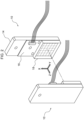
- Fig. 1 is a perspective view illustrating an example of the robot system 100.
- the robot system 100 has a robot 102 and a controller 104.
- the robot 102 is an articulated robot for example, and has a robot arm 106 and a robot hand 108.
- the robot arm 106 has plural joint portions 110.
- the robot hand 108 is provided at the distal end portion of the robot arm 106.
- the robot hand 108 is connected to the distal end portion of the robot arm 106 via a wrist joint portion 112.
- a pair of grasping portions 114 are provided at the robot hand 108.
- the pair of grasping portions 114 are disposed so as to face one another.
- the pair of grasping portions 114 approach and move away from one another in the direction in which they face one another, due to the driving of an unillustrated driving section.
- the pair of grasping portions 114 move in directions of approaching one another in a state in which a workpiece W is disposed therebetween, the workpiece W is grasped by the pair of grasping portions 114.
- the controller 104 controls the robot 102, and is electrically connected to the robot 102.
- the controller 104 is connected to the robot 102 by a wire, but the controller 104 may be wirelessly connected to the robot 102.
- the tactile sensing system 1 is installed in the robot system 100.
- the tactile sensing system 1 has a pair of tactile sensors 10 and an output section 12.
- the pair of tactile sensors 10 are provided respectively at mutually facing surfaces 114A of the pair of grasping portions 114.
- the pair of tactile sensors 10 are provided at positions that contact the workpiece W in the state in which the workpiece W is grasped by the pair of grasping portions 114, i.e., as an example, are provided at the portions, which face one another, of the distal end portions of the pair of grasping portions 114.
- the output section 12 is electrically connected to the pair of tactile sensors 10.
- the output section 12 may be connected to the pair of tactile sensors 10 by wires, or may be wirelessly connected to the pair of tactile sensors 10.
- the output section 12 has the functions of carrying out various types of processings on the basis of data outputted from the pair of tactile sensors 10, and outputting data that is based on the results of these processings to the controller 104.
- the output section 12 is provided at the wrist joint portion 112 as an example.
- Fig. 2 is a perspective view illustrating an example of the pair of tactile sensors 10 of Fig. 1 .
- the pair of tactile sensors 10 have plane symmetry in the direction of facing one another.
- the X-axis direction corresponds to a first direction that is orthogonal to the direction in which the pair of tactile sensors 10 face one another.
- the Y-axis direction corresponds to a second direction that is orthogonal to the direction in which the pair of tactile sensors 10 face one another.
- the Z-axis direction corresponds to the direction in which the pair of tactile sensors 10 face one another.
- the X-axis direction is orthogonal to the Y-axis direction.
- the X-axis direction corresponds to the length direction of the tactile sensors 10
- the Y-axis direction corresponds to the width direction of the tactile sensors 10.
- the tactile sensor 10 has a supporting plate 14, a substrate 16, and a sensor portion 18.
- the supporting plate 14 is configured by a body that is separate from the above-described grasping portion 114 (see Fig. 1 ), and is fixed to the grasping portion 114.
- the supporting plate 14 may be structured integrally with the grasping portion 114.
- the substrate 16 is fixed to the supporting plate 14, and the sensor portion 18 is provided on the substrate 16. Details of the sensor portion 18 are described later.
- a first embodiment is described first.
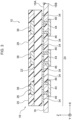
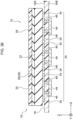
- Fig. 3 is a vertical sectional view of the tactile sensor 10 relating to the first embodiment.
- the tactile sensor 10 relating to the first embodiment has the sensor portion 18 and the substrate 16.
- the sensor portion 18 is an electrostatic capacitance-type sensor. More specifically, this sensor portion 18 is a self-capacitance-type sensor, and has a layered structure in which plural layers are layered. Namely, the sensor portion 18 has, as the plural layers, an insulating layer 20, an elastic layer 22, a first electrode layer 24 and a second electrode layer 26. The first electrode layer 24 and the second electrode layer 26 are positioned at the respective sides of the elastic layer 22 so as to sandwich the elastic layer 22 therebetween.
- the insulating layer 20 is positioned at the side of the second electrode layer 26, which side is opposite the elastic layer 22.
- the insulating layer 20 forms the surface layer portion of the sensor portion 18.
- the obverse of the insulating layer 20 is formed as a contacting surface 28 that contacts the workpiece W (see Fig. 1 ). Note that the insulating layer 20 may be omitted. In a case in which the insulating layer 20 is omitted, the obverse of the second electrode layer 26, or of a surface layer formed on the second electrode layer 26, is the contacting surface 28.
- the elastic layer 22 is a dielectric.
- the elastic layer 22 is flexible and elastic.
- the elastic layer 22 is formed by a gel for example.
- the insulating layer 20, the elastic layer 22, the first electrode layer 24 and the second electrode layer 26 are layered in the Z-axis direction.
- the Z-axis direction corresponds to the normal direction of the contacting surface 28.
- the insulating layer 20, the elastic layer 22, the first electrode layer 24 and the second electrode layer 26 are adhered to one another by an adhesive or the like for example.
- the insulating layer 20 be a size that covers the entire surface of the second electrode layer 26.
- the first electrode layer 24 has plural first electrodes 34.
- the plural first electrodes 34 are formed on a first surface 16A that is at the sensor portion 18 side of the substrate 16.
- Plural electrostatic capacitance detecting ICs (Integrated Circuits) 44 are packaged on a second surface 16B, which is at the side opposite the sensor portion 18, of the substrate 16.
- the plural first electrodes 34 and the plural electrostatic capacitance detecting ICs 44 are connected by through-hole vias 46 that extend in the plate thickness direction of the substrate 16.
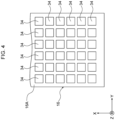
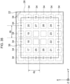
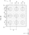
- Fig. 4 is a plan view of the substrate 16 of Fig. 3 .
- the plural first electrodes 34 that are formed on the first surface 16A of the substrate 16 are arrayed in the form of a matrix along the X-Y plane. Namely, the plural first electrodes 34 are arrayed with the X-axis direction being the length direction and the Y-axis direction being the width direction.
- the X-Y plane is the plane that is parallel to the aforementioned contacting surface 28 (see Fig. 2 )
- the plural first electrodes 34 are independent of one another.
- the plural first electrodes 34 have the same shape.
- the plural first electrodes 34 are formed in square shapes as viewed in plan view. Viewing in plan view corresponds to viewing in the Z-axis direction.
- the plural first electrodes 34 are arrayed such that there are six thereof in the X-axis direction and six thereof in the Y-axis direction. Namely, the number of the plural first electrodes 34 is 36.
- These plural first electrodes 34 are arrayed at uniform intervals in the X-axis direction and the Y-axis direction, respectively.
- Fig. 5 is a plan view of the second electrode layer 26 of Fig. 3 .
- the second electrode layer 26 is configured by plural second electrodes 36 that are a single layer.
- the plural second electrodes 36 are formed of a conductive rubber for example.
- the plural second electrodes 36 are respectively formed in the shapes of flat plates.
- the plural second electrodes 36 may be connected to the ground of the substrate 16, or may be floating with respect to ground.
- the plural second electrodes 36 form plural islands that are independent of one another.
- the plural second electrodes 36 are arrayed in the form of a matrix along the X-Y plane. Namely, the plural second electrodes 36 are arrayed with the X-axis direction being the length direction and the Y-axis direction being the width direction.
- the plural second electrodes 36 are the same shape. As an example, the plural second electrodes 36 are respectively formed in square shapes as viewed in plan view. The number of the plural second electrodes 36 is less than the number of the above-described, plural first electrodes 34 (see Fig. 4 ). As an example, the plural second electrodes 36 are arrayed such that there are three thereof in the X-axis direction and three thereof in the Y-axis direction. Namely, the number of the plural second electrodes 36 is nine. These plural second electrodes 36 are arrayed at uniform intervals in the X-axis direction and the Y-axis direction, respectively.
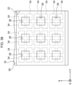
- Fig. 6 is a plan view illustrating a state in which the plural second electrodes 36 and the elastic layer 22 and the substrate 16 of Fig. 3 are superposed.
- the plural second electrodes 36 are disposed so as to be superposed with all of the plural first electrodes 34 as viewed in plan view.
- the plural second electrodes 36 are respectively formed so as to partially overlap with the respective, four first electrodes 34 that are adjacent in the X-axis direction and the Y-axis direction, among the plural first electrodes 34.
- the respective second electrodes 36 are positioned at the central portions of the four first electrodes 34, and partially overlap with these four first electrodes 34.
- all of the plural first electrodes 34 partially overlap with the plural second electrodes 36.
- all of the plural first electrodes 34 correspond to an example of the "plurality of partially-overlapping electrodes that partially overlap with the plurality of second electrodes"
- the plural signals that are outputted from the plural first electrodes 34 correspond to an example of the "plurality of partially-overlapping electrode signals”.
- Electrostatic capacitance C[F] between the first electrode 34 and the second electrode 36 is determined by the following formula.
- C ⁇ ⁇ A / d ⁇ is the dielectric constant [Fm -1 ] of the elastic layer 22, A is the surface area [m 2 ] over which the first electrode 34 and the second electrode 36 overlap one another as viewed in plan view, and d is the distance [m] between the first electrode 34 and the second electrode 36 along the Z-axis direction.
- the electrostatic capacitance C changes in accordance with this change in the distance d. Further, at the sensor portion 18, when shearing force is applied to the contacting surface 28, and the surface area A over which each first electrode 34 and the second electrode 36 overlap one another changes, the electrostatic capacitance C changes in accordance with this change in the surface area A.
- the pressure that is applied to the contacting surface 28 corresponds to the force that is applied to the contacting surface 28 along the Z-axis direction.
- the shearing force that is applied to the contacting surface 28 corresponds to the force that is applied to the contacting surface 28 along a direction orthogonal to the Z-axis direction.
- Directions orthogonal to the Z-axis direction include the X-axis direction, the Y-axis direction, and directions that combine the X-axis direction and the Y-axis direction.
- the plural first electrodes 34 are driven by the electrostatic capacitance detecting ICs 44 (see Fig. 3 and Fig. 7 ) that are described later, and respectively output signals corresponding to the electrostatic capacitances C between the first electrodes 34 and the second electrodes 36.
- the sensor portion 18 outputs plural signals that respectively correspond to the plural first electrodes 34. These plural signals are analog signals.
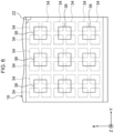
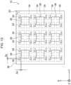
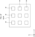
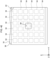
- Fig. 7 is a bottom view of the substrate 16 of Fig. 3 .
- the plural electrostatic capacitance detecting ICs 44 are arrayed in the form of a matrix along the X-Y plane. Namely, the plural electrostatic capacitance detecting ICs 44 are arrayed with the X-axis direction being the length direction and the Y-axis direction being the width direction.
- the plural electrostatic capacitance detecting ICs 44 have the same structure. As an example, the plural electrostatic capacitance detecting ICs 44 are arrayed such that there are three thereof in the X-axis direction and three thereof in the Y-axis direction. Namely, the number of the plural electrostatic capacitance detecting ICs 44 is nine.
- each of the electrostatic capacitance detecting ICs 44 is connected the four first electrodes 34 that overlap that electrostatic capacitance detecting IC as viewed in plan view.
- Each of the electrostatic capacitance detecting ICs 44 drives the four first electrodes 34, and is a structure that can output data corresponding to the signals outputted from those four first electrodes 34.
- Fig. 8 is a drawing explaining an example of a method of manufacturing the tactile sensor 10 of Fig. 3 .
- the tactile sensor 10 is manufactured by the following procedures for example. Namely, the plural electrostatic capacitance detecting ICs 44 are packaged on the second surface 16B of the substrate 16 at which the plural first electrodes 34 are formed on the first surface 16A by a pattern. The plural through-hole vias 46 are formed in the substrate 16, and the plural electrostatic capacitance detecting ICs 44 are connected to the plural first electrodes 34 via the plural through-hole vias 46.
- the elastic layer 22 is layered on the first electrode layer 24 that has the plural first electrodes 34.
- the second electrode layer 26 that is configured by the plural second electrodes 36 (see Fig. 5 ) is layered on the elastic layer 22, and moreover, the insulating layer 20 is layered on this second electrode layer 26.
- the insulating layer 20, the elastic layer 22, the first electrode layer 24 and the second electrode layer 26 are adhered to one another by an adhesive or the like for example.
- the tactile sensor 10 is manufactured by the above-described procedures.
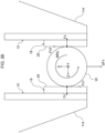
- Fig. 9 is a drawing illustrating a first example of a state in which the workpiece W is grasped by the pair of grasping portions 114 of Fig. 1 .
- the workpiece W is a cylinder or a sphere.
- positions that contact the workpiece W and where the pressure is high, and positions that do not contact the workpiece W and to which pressure is not applied, arise within the contacting surfaces 28. Namely, the pressure distributions of the contacting surfaces 28 are non-uniform.
- Fig. 10 is a drawing illustrating a second example of a state in which the workpiece W is grasped by the pair of grasping portions 114 of Fig. 1 .
- the workpiece W is a quadrangular pillar or a rectangular parallelepiped.
- the surfaces of the workpiece W are larger than the contacting surfaces 28.
- pressure is applied uniformly to the contacting surfaces 28. Namely, the pressure distributions of the contacting surfaces 28 are uniform.
- normal loads Fz' which are the reaction forces of grasping forces Fz of the pair of grasping portions 114 in the directions opposite the grasping forces Fz, are applied to the contacting surfaces 28.
- the grasping forces Fz and the normal loads Fz' are forces along the Z-axis direction.
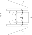
- Fig. 11 is a drawing illustrating an example of shearing forces Fx, Fy and moments Mx, My, Mz applied to the contacting surface 28 of the tactile sensor 10 of Fig. 3 .
- the shearing force Fx is a force along the X-axis direction
- the shearing force Fy is a force along the Y-axis direction.
- the moment Mx is the moment around the X-axis direction
- the moment My is the moment around the Y-axis direction
- the moment Mz is the moment around the Z-axis direction.
- Fig. 12 is a drawing illustrating an example of moment lengths dx, dy at the tactile sensor 10 of Fig. 3 .
- identification numbers 1 ⁇ 9 are illustrated for the plural second electrodes 36.
- the plural second electrodes 36 are called the second electrodes 36-1 ⁇ 9, respectively.
- the moment length dx illustrated in Fig. 12 is the length used at the time of calculating the moment Mx around the X-axis direction (see Fig. 11 ).
- the moment length dx corresponds to the distance along the Y-axis direction between the center of the contacting surface 28 and the center of the second electrode 36-3 that is at a position that is apart in the Y-axis direction from the center of the contacting surface 28.
- the moment length dy illustrated in Fig. 12 is the length used at the time of calculating the moment My around the Y-axis direction (see Fig. 11 ).
- the moment length dy corresponds to the distance along the X-axis direction between the center of the contacting surface 28 and the center of the second electrode 36-1 that is at a position that is apart in the X-axis direction from the center of the contacting surface 28.
- Fig. 13 is a plan view explaining an example of displacement ⁇ x and displacement ⁇ y at the tactile sensor 10 of Fig. 3 . Note that, in Fig. 13 , electrostatic capacitances C 00 ⁇ C 55 between the respective, plural first electrodes 34 and the second electrodes 36 are illustrated so as to correspond to the plural first electrodes 34, respectively.
- Fig. 14 is a drawing explaining examples of displacement ⁇ x and displacement ⁇ z at the tactile sensor 10 of Fig. 3 .
- (A) illustrates a case in which there is no normal load Fz'
- (B) illustrates a case in which there is the normal load Fz'
- (C) illustrates a case in which there is the shearing force Fx
- (D) illustrates a case in which there is the normal load Fz' and there is the shearing force Fx, respectively.
- Fig. 15 is a drawing explaining examples of displacement ⁇ y and displacement ⁇ z at the tactile sensor 10 of Fig. 3 .
- (A) illustrates a case in which there is no normal load Fz'
- (B) illustrates a case in which there is the normal load Fz'
- (C) illustrates a case in which there is the shearing force Fy
- (D) illustrates a case in which there is the normal load Fz' and there is the shearing force Fy, respectively.
- displacement ⁇ x corresponds to the distance that the second electrode 36 moves along the X-axis direction accompanying application of the shearing force Fx.
- displacement ⁇ y corresponds to the distance that the second electrode 36 moves along the Y-axis direction accompanying application of the shearing force Fy.
- distance Z 0 corresponds to the distance along the Z-axis direction between the first electrode 34 and the second electrode 36 at the time when the normal load Fz' is not applied.
- Displacement ⁇ z corresponds to the distance that the second electrode 36 moves along the Z-axis direction toward the first electrode 34 side accompanying application of the normal load Fz'.
- Examples of calculating the displacements ⁇ x, ⁇ y, ⁇ z are described hereinafter by using the first electrodes 34, which are adjacent to one another and partially overlap with one of the second electrodes 36, as an example.
- C 00 _ z K 1 / Z 0 ⁇ ⁇ z
- C 01 _ z K2 / Z 0 ⁇ ⁇ z
- C 01_z are the electrostatic capacitances between the adjacent first electrodes 34 and the second electrode 36 when only the normal load Fz' is applied.
- the displacement ⁇ z of the second electrode 36 with respect to one first electrode 34 is determined as follows.
- the displacement ⁇ z of the second electrode 36 with respect to the other first electrode 34 is determined as follows.
- ⁇ z K2 1 / C 01 _ 0 ⁇ 1 / C 01 _ z
- the displacement ⁇ z of the second electrode 36 with respect to the other first electrodes 34 is determined in the same way as described above.
- C 00 _ x K 1 / Z 0 + ⁇ x ⁇ Kp / Z 0
- C 01 _ x K2 / Z 0 ⁇ ⁇ x ⁇ Kp / Z 0
- C 01_x are the electrostatic capacitances between the first electrodes 34 that are adjacent to one another in the x direction and the second electrode 36 when only the shearing force Fx is applied, and Kp is a constant.
- the displacement ⁇ x of the second electrode 36 with respect to the other first electrode 34 is determined as follows.
- ⁇ x Z 0 / Kp ⁇ C 01 _ 0 ⁇ C 01 _ x
- the displacement ⁇ x of the second electrode 36 with respect to the other first electrodes 34 is determined in the same way as described above.
- the displacement ⁇ y of the second electrode 36 with respect to the first electrode 34 is determined by calculation that is similar to when only the shearing force Fx is applied.
- C 00_zx K 1 / Z 0 ⁇ ⁇ z + ⁇ x ⁇ Kp / Z 0 ⁇ ⁇ z
- C 01 _ zx K 2 / Z 0 ⁇ ⁇ z ⁇ ⁇ x ⁇ Kp / Z 0 ⁇ ⁇ z
- C 01_zx are the electrostatic capacitances between the first electrodes 34 and the second electrode 36 when the normal load Fz' and only the shearing force Fx are applied.
- the displacements ⁇ z, ⁇ x of the second electrode 36 with respect to the first electrode 34 are determined as follows.
- the displacements ⁇ z, ⁇ x of the second electrode 36 with respect to the other first electrode 34 are determined in the same way as described above.
- the displacements ⁇ z, ⁇ y of the second electrode 36 with respect to the first electrodes 34 that are adjacent to one another are determined by calculation that is similar to when the normal load Fz' and only the shearing force Fx are applied.
- the displacements ⁇ x, ⁇ y, ⁇ z of the second electrode 36 with respect to the first electrode 34 can be determined as follows. In the range of the four first electrodes 34 that partially overlap with the one second electrode 36, it is often the case that the values of the displacement ⁇ z at the respective first electrodes 34 approximate one another, and therefore, it is assumed that the value of the displacement ⁇ z can be used in common therefor. In this case, the magnitude of the signal (the electrostatic capacitance value) corresponding to each first electrode 34 is proportional to the surface area of overlapping of the first electrode 34 with the second electrode 36.
- the ratio of electrostatic capacitance values C 00 , C 01 , C 10 , C 11 is equal to the ratio of overlapping surface areas S 00 , S 01 , S 10 , S 11 .
- Formula 5 is established.
- C 00 : C 01 : C 10 : C 11 S 00 : S 01 : S 10 : S 11
- the overlapping surface areas S 00 , S 01 , S 10 , S 11 are expressed by Formula 6.
- S 00 a ⁇ ⁇ x ⁇ a ⁇ ⁇ y
- S 01 a ⁇ ⁇ x ⁇ a + ⁇ y
- S 10 a + ⁇ x ⁇ a ⁇ ⁇ y
- S 11 a + ⁇ x ⁇ a + ⁇ y
- the sum of the four overlapping surface areas is 4a 2 and is a constant. Accordingly, the overlapping surface areas S 00 , S 01 , S 10 , S 11 become known values from Formula 5 and the sum 4a 2 of the four overlapping surface areas. Due to the above, the unknown displacements ⁇ x, ⁇ y can be calculated from the simultaneous equations of Formula 6.
- the displacement ⁇ z that is assumed to be a common value may be corrected to the individual displacements ⁇ z at the respective first electrodes 34.
- This correction can be carried out by, for example, acquiring in advance and utilizing correlations between the displacements ⁇ x, ⁇ y and the four displacements ⁇ z in an environment in which true values of the four displacements ⁇ z can be measured by another means.
- the acquisition of the correlations may be carried out by machine learning.
- the displacement ⁇ z is treated as a known value, and the displacements ⁇ x, ⁇ y can be determined more accurately.
- calculating the respective pressure values of the plurality of pressure detecting positions includes, in a case of assuming that the displacement ⁇ z is common at plural pressure detecting positions such as the four first electrodes 34, treating the pressure value, which is based on the common displacement ⁇ z that is calculated, as the pressure value at the respective pressure detecting positions.
- calculating an aggregate pressure value by carrying out calculation of a representative value of the respective pressure values of the plurality of pressure detecting positions includes, in a case of assuming that the displacement ⁇ z is common at plural pressure detecting positions such as the four first electrodes 34, calculating the aggregate pressure value by using the pressure value, which is based on the common displacement ⁇ z that is calculated, as a representative value.
- the output section 12 calculates the respective shearing force Fx, Fy values so as to eliminate the effects of pressure on the plural signals.
- Fig. 16 is a block drawing illustrating an example of hardware structures of the tactile sensor 10, the output section 12 and the controller 104 of Fig. 1 .
- the output section 12 has a first multiplexer 50, a second multiplexer 52, a CPU (Central Processing Unit) 54, a ROM (Read Only Memory) 56, and a RAM (Random Access Memory) 58.
- CPU Central Processing Unit
- ROM Read Only Memory
- RAM Random Access Memory
- the plural electrostatic capacitance detecting ICs 44 are connected to the first multiplexer 50 and the second multiplexer 52.
- the data that is outputted from the plural electrostatic capacitance detecting ICs 44 is inputted to the first multiplexer 50 and the second multiplexer 52.
- the first multiplexer 50 and the second multiplexer 52 are connected to the CPU 54.
- the data outputted from the first multiplexer 50 and the second multiplexer 52 are inputted to the CPU 54.
- Data outputted from the controller 104 that is described later is inputted to the CPU 54.
- the CPU 54 uses the RAM 58 as a primary storage region, and executes a program 60 that is stored in the ROM 56. As will be described later, various processes for the CPU 54 to carry out computation on the basis of data outputted from the tactile sensors 10 and data outputted from the controller 104, and for the CPU 54 to output data to the controller 104, are recorded in the program 60.
- the output section 12 is connected by a wire or wirelessly to the controller 104 such that communication therebetween is possible.
- the controller 104 has a CPU 124, a ROM 126 and a RAM 128. Data outputted from the output section 12 is inputted to the CPU 124.
- the CPU 124 utilizes the RAM 128 as a primary storage region, and executes a program 130 that is stored in the ROM 126. As will be described later, various processes for outputting data by which the controller 104 causes the robot 102 to move and requests data from the output section 12, are recorded in the program 130.
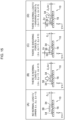
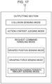
- Fig. 17 is a drawing illustrating an example of plural modes at the output section 12 of Fig. 16 .
- the output section 12 has a collision sensing mode, an action content judging mode, and a request command handling mode.
- the collision sensing mode is a mode that, in a case in which a collision of the workpiece is sensed on the basis of data outputted from the tactile sensors 10, outputs collision sensing data to the controller 104.
- a collision of the workpiece is an unforeseen object colliding with the workpiece.
- the collision sensing data may selectively include at least any of data of the grasping force (aggregate pressure) Fz value, data of the aggregate shearing force Fx value, and data of the aggregate shearing force Fy value, which are described later.
- the output section 12 outputs the collision sensing data to the controller 104 regardless of the absence/presence of an instruction from the controller 104, and the controller 104 processes the collision sensing data in an interruption processing.
- the respective pressure values of plural pressure detecting positions within the contacting surface 28 are calculated, and a collision of the workpiece is sensed in a case in which at least a predetermined number of pressure values among the respective pressure values of the plural pressure detecting positions exceeds a threshold value, or a case in which an aggregate pressure value that is described later exceeds a threshold value, or a case in which the aggregate shearing force Fx value that is described later exceeds a threshold value, or a case in which the aggregate shearing force Fy value that is described later exceeds a threshold value.
- the action content judging mode is a mode in which the content of an action of the robot 102 is judged on the basis of data outputted from the controller 104, and, in accordance with the content of the action, at least any of data of the pressure distribution, data of the grasping force Fz value, data of the aggregate shearing force Fx value, data of the aggregate shearing force Fy value, data of the moment Mx value, data of the moment My value, and data of the moment Mz value is selectively outputted. Which data is to be outputted is judged and decided upon by the output section 12 in accordance with the content of the action of the robot 102.
- Contents of actions of the robot 102 are, for example, actions such as grasping the workpiece W by the robot hand 108 illustrated in Fig. 1 , the robot arm 106 moving so as to move the workpiece W while grasping the workpiece W by the robot hand 108, the robot arm 106 moving so as to search for the destination of movement while the workpiece contacts an object, the robot arm 106 moving such that the workpiece W is inserted in the destination of movement, the robot hand 108 releasing the workpiece W, and the like.
- the request command handling mode illustrated in Fig. 17 is a mode that, in accordance with a request command included in data outputted from the controller 104, selectively outputs at least any of data of the pressure distribution, data of the grasping force Fz value, data of the grasped position, data of the aggregate shearing force Fx value, data of the aggregate shearing force Fy value, data of the moment Mx value, data of the moment My value, and data of the moment Mz value, which are described later.
- the request command handling mode includes a grasped position sensing mode, a grasping force sensing mode, and an insertion characteristic amount sensing mode.
- the grasped position sensing mode is a mode that is designated by the controller 104 when the pair of grasping portions 114 illustrated in Fig. 1 grasp the workpiece W.
- This grasped position sensing mode is a mode that outputs data of the pressure distribution or data of the grasped position.
- the grasping force sensing mode is a mode that is designated by the controller 104, for example, in the process in which the pair of grasping portions 114 illustrated in Fig. 1 transition from the open state to the closed state.
- This grasping force sensing mode is a mode that outputs data of the grasping force Fz value.
- the insertion characteristic amount sensing mode is a mode that is designated by the controller 104, for example, at the time of carrying out detection of contact of the robot hand 108 illustrated in Fig. 1 with the workpiece W, detection of the maintaining of contact of the robot hand 108 with the workpiece W, detection of the position of fitting the workpiece W into the destination of movement, detection of offset of the position of fitting the workpiece W into the destination of movement, detection of offset of the posture of inserting the workpiece W into the destination of movement, detection of completion of insertion of the workpiece W into the destination of movement, detection of completion of pulling the workpiece W out of the destination of movement, and the like.
- the insertion characteristic amount sensing mode is a mode that outputs data of the grasping force Fz value, data of the aggregate shearing force Fx value, data of the aggregate shearing force Fy value, data of the moment Mx value, data of the moment My value and data of the moment Mz value, as 6-axis information.
- the output section 12 outputs data of the translational force ⁇ x value, data of the translational force ⁇ y value, or a rotational moment Mr value, which are described later.
- the output section 12 outputs data of the pressure distribution that expresses the respective pressure values of the plural pressure detecting positions within the contacting surface 28.
- the pressure detecting positions are the positions of the respective first electrodes 34.
- the position of the first electrode 34 is expressed by the position of a specific region of the first electrode 34, such as the center of or any corner of or the like of the first electrode 34.
- Fig. 18 is a flowchart illustrating an example of the flow of the processing of outputting data of the pressure distribution at the output section 12 of Fig. 16 .
- the CPU 54 acquires the data outputted from the plural electrostatic capacitance detecting ICs 44.
- This data acquired in step S 1 is data of the signals outputted from the sensor portion 18 in correspondence with the first electrodes 34 that are the objects of calculation of displacement ⁇ z in step S2 described hereinafter.
- step S2 on the basis of the data acquired in step S1, the CPU 54 calculates the respective displacements ⁇ z of the plural pressure detecting positions within the contacting surface 28.
- the respective displacements ⁇ z of the plural pressure detecting positions corresponding to all of the plural first electrodes 34 may be calculated on the basis of the data of all of the plural signals outputted from the sensor portion 18, or the respective displacements ⁇ z of the plural pressure detecting positions corresponding to some of the plural first electrodes 34 may be calculated on the basis of the data of some of the plural signals outputted from the sensor portion 18.
- the respective displacements ⁇ z of the plural pressure detecting positions calculated in this way are proportional to the respective pressure values of the plural pressure detecting positions. Accordingly, by calculating the respective displacements ⁇ z of the plural pressure detecting positions, the respective pressure values of the plural pressure detecting positions are calculated.
- step S3 the CPU 54 generates data of the pressure distribution on the basis of the respective pressure values of the plural pressure detecting positions within the contacting surface 28 that were calculated in step S2.
- step S4 the CPU 54 outputs the data of the pressure distribution that was generated in step S3 to the controller 104.
- This data of the pressure distribution is used, for example, at the controller 104 in understanding the grasped position and grasped posture of the workpiece W whose shape is already known, and in carrying out identification of the workpiece W based on the shape.
- the output section 12 specifies the grasped position of the workpiece W within the contacting surface 28, and outputs data of the grasped position.
- This processing of outputting data of the grasped position is executed at the CPU 54 of the output section 12 by the following procedures for example.
- Fig. 19 is a flowchart illustrating an example of the flow of the processing of outputting data of the grasped position at the output section 12 of Fig. 16 .
- the CPU 54 acquires the data outputted from the plural electrostatic capacitance detecting ICs 44.
- This data acquired in step S11 is data of the signals outputted from the sensor portion 18 in correspondence with the first electrodes 34 that are the objects of calculation of displacement ⁇ z in step S12 described hereinafter.
- step S12 on the basis of the data acquired in step S11, the CPU 54 calculates the respective displacements ⁇ z of the plural pressure detecting positions within the contacting surface 28.
- the respective displacements ⁇ z of the plural pressure detecting positions corresponding to all of the plural first electrodes 34 may be calculated on the basis of the data of all of the plural signals outputted from the sensor portion 18, or the respective displacements ⁇ z of the plural pressure detecting positions corresponding to some of the plural first electrodes 34 may be calculated on the basis of the data of some of the plural signals outputted from the sensor portion 18.
- the respective displacements ⁇ z of the plural pressure detecting positions calculated in this way are proportional to the respective pressure values of the plural pressure detecting positions. Accordingly, by calculating the respective displacements ⁇ z of the plural pressure detecting positions, the respective pressure values of the plural pressure detecting positions are calculated.
- the CPU 54 specifies positions at which the respective pressure values of the plural pressure detecting positions within the contacting surface 28 that were calculated in step S12, become predetermined interrelationships.
- the center of gravity position of the region where pressure is being applied may be specified as the grasped position.
- the shape of the region where pressure is being applied may be a planar shape, a strip shape, a dot shape (a planar shape of a small surface area), a linear shape (a strip shape of a small width), or the like.
- the position of a borderline between a region where pressure is not being applied and a region where pressure is being applied may be specified as the grasped position. Due thereto, the grasped position of the workpiece W within the contacting surface 28 is specified on the basis of the respective pressure values of the plural pressure detecting positions within the contacting surface 28.
- step S14 the CPU 54 outputs the data (data of the X-Y coordinate) of the grasped position that was specified in step S13 to the controller 104.
- This data of the grasped position is used, for example, at the controller 104 in specifying the grasped position of the workpiece W.
- the output section 12 calculates one aggregate pressure value for the entire contacting surface 28, and outputs the data of the aggregate pressure value as data of the grasping force Fz value. This processing of outputting the data of the grasping force Fz value is executed at the CPU 54 of the output section 12 by the following procedures for example.
- Fig. 20 is a flowchart illustrating an example of the flow of the processing of outputting data of the grasping force Fz value at the output section 12 of Fig. 16 .
- the CPU 54 acquires the data outputted from the plural electrostatic capacitance detecting ICs 44.
- This data acquired in step S21 is data of the signals outputted from the sensor portion 18 in correspondence with the first electrodes 34 that are the objects of calculation of displacement ⁇ z in step S22 described hereinafter.
- step S22 on the basis of the data acquired in step S21, the CPU 54 calculates the respective displacements ⁇ z of the plural pressure detecting positions within the contacting surface 28.
- the respective displacements ⁇ z of the plural pressure detecting positions corresponding to all of the plural first electrodes 34 may be calculated on the basis of the data of all of the plural signals outputted from the sensor portion 18, or the respective displacements ⁇ z of the plural pressure detecting positions corresponding to some of the plural first electrodes 34 may be calculated on the basis of the data of some of the plural signals outputted from the sensor portion 18.
- the respective displacements ⁇ z of the plural pressure detecting positions calculated in this way are proportional to the respective pressure values of the plural pressure detecting positions. Accordingly, by calculating the respective displacements ⁇ z of the plural pressure detecting positions, the respective pressure values of the plural pressure detecting positions are calculated.
- step S23 the CPU 54 calculates an aggregate pressure value by carrying out at least any of calculating a representative value, calculating the total value and calculating the average value for the respective pressure values of the plural pressure detecting positions within the contacting surface 28 that were calculated in step S22.
- step S24 the CPU 54 outputs the data of the aggregate pressure value that was calculated in step S23 to the controller 104 as data of the grasping force Fz value.
- This data of the grasping force Fz value is used, for example, at the controller 104 in adjusting the grasping force Fz in order to make it such that the workpiece W does not fall down, adjusting the grasping force Fz in accordance with the weight or the ease of breakage or the like of the workpiece W, or the like.
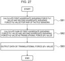
- the output section 12 calculates one aggregate shearing force Fx value for the entire contacting surface 28, and outputs the data of the aggregate shearing force Fx value. This processing of outputting the data of the aggregate shearing force Fx value is executed at the CPU 54 of the output section 12 by the following procedures for example.
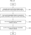
- Fig. 21 is a flowchart illustrating an example of the flow of the processing of outputting data of the aggregate shearing force Fx value at the output section 12 of Fig. 16 .
- the CPU 54 acquires the data outputted from the plural electrostatic capacitance detecting ICs 44.
- This data acquired in step S31 is data of the signals outputted from the sensor portion 18 in correspondence with the first electrodes 34 that are the objects of calculation of displacement ⁇ x in step S32 described hereinafter.
- step S32 on the basis of the data acquired in step S31, the CPU 54 calculates the respective displacements ⁇ x for the positions of the plural second electrodes 36 as an example of the "plurality of shearing force detecting positions".
- the position of the second electrode 36 is expressed by the position of a specific region of the second electrode 36, such as the center of or any corner of or the like of the second electrode 36.
- the calculating of the displacement ⁇ x is carried out by using all of or some of the signals corresponding to the four first electrodes 34 that partially overlap with the one second electrode 36, in accordance with the description of the above-described case in which ⁇ x, ⁇ y, ⁇ z ⁇ 0.
- the signals corresponding to at least two electrodes whose positions in the x direction are different, among the four first electrodes 34 that overlap the one second electrode 36 are used.
- the plural second electrodes 36 that are the objects of calculation of the displacement ⁇ x may be all of the second electrodes 36 among the second electrodes 36, or may be some of the second electrodes 36 among the second electrodes 36.
- all of the plural signals outputted from the sensor portion 18 may be used, or some of the plural signals may be used.
- the displacements ⁇ x which are calculated for the respective positions of the plural second electrodes 36 and are calculated in this way, are proportional to the shearing force Fx values at the respective positions of the plural second electrodes 36. Accordingly, due to the displacements ⁇ x being calculated for the respective positions of the plural second electrodes 36, the shearing force Fx values at the respective positions of the plural second electrodes 36 are calculated.
- the shearing force Fx values that are calculated for the respective positions of the plural second electrodes 36 correspond to an example of the "respective shearing force values of the plurality of shearing force detecting positions within the contacting surface".
- step S33 the CPU 54 calculates the aggregate shearing force Fx value by carrying out at least any of calculating a representative value, calculating the total value and calculating the average value for the shearing force Fx values at the respective positions of the plural second electrodes 36 that were calculated in step S32.
- step S34 the CPU 54 outputs the data of the aggregate shearing force Fx value that was calculated in step S33 to the controller 104.
- This data of the aggregate shearing force Fx value is used in sensing a collision of the workpiece W, detecting the maintaining of contact of the workpiece W held at the robot hand 108 with another object, detecting the position of fitting the workpiece W into the destination of movement, detecting the completion of insertion of the workpiece W into the destination of movement, detecting the completion of pulling of the workpiece W out from the destination of movement, or the like.
- the output section 12 calculates one aggregate shearing force Fy value for the entire contacting surface 28, and outputs the data of the aggregate shearing force Fy value. This processing of outputting the data of the aggregate shearing force Fy value is executed at the CPU 54 of the output section 12 by the following procedures for example.
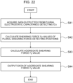
- Fig. 22 is a flowchart illustrating an example of the flow of the processing of outputting data of the aggregate shearing force Fy value at the output section 12 of Fig. 16 .
- step S41 the CPU 54 acquires the data outputted from the plural electrostatic capacitance detecting ICs 44.
- This data acquired in step S41 is data of the signals outputted from the sensor portion 18 in correspondence with the first electrodes 34 that are the objects of calculation of displacement ⁇ y in step S42 described hereinafter.
- step S42 on the basis of the data acquired in step S41, the CPU 54 calculates the respective displacements ⁇ y for the positions of the plural second electrodes 36 as an example of the "plurality of shearing force detecting positions".
- the position of the second electrode 36 is expressed by the position of a specific region of the second electrode 36, such as the center of or any corner of or the like of the second electrode 36.
- the calculating of the displacement ⁇ y is carried out by using all of or some of the signals corresponding to the four first electrodes 34 that partially overlap with the one second electrode 36, in accordance with the description of the above-described case in which ⁇ x, ⁇ y, ⁇ z ⁇ 0.
- the signals corresponding to at least two electrodes whose positions in the y direction are different, among the four first electrodes 34 that overlap the one second electrode 36 are used.
- the plural second electrodes 36 that are the objects of calculation of the displacement ⁇ y may be all of the second electrodes 36 among the second electrodes 36, or may be some of the second electrodes 36 among the second electrodes 36.
- all of the plural signals outputted from the sensor portion 18 may be used, or some of the plural signals may be used.
- the displacements ⁇ y which are calculated for the respective positions of the plural second electrodes 36 in this way, are proportional to the shearing force Fy values at the respective positions of the plural second electrodes 36. Accordingly, due to the displacements ⁇ y being calculated for the respective positions of the plural second electrodes 36, the shearing force Fy values at the respective positions of the plural second electrodes 36 are calculated.
- the shearing force Fy values that are calculated for the respective positions of the plural second electrodes 36 correspond to an example of the "respective shearing force values of the plurality of shearing force detecting positions within the contacting surface".
- step S43 the CPU 54 calculates the aggregate shearing force Fy value by carrying out at least any of calculating a representative value, calculating the total value and calculating the average value for the shearing force Fy values at the respective positions of the plural second electrodes 36 that were calculated in step S42.
- step S44 the CPU 54 outputs the data of the aggregate shearing force Fy value that was calculated in step S43 to the controller 104.
- This data of the aggregate shearing force Fy value is used in sensing a collision of the workpiece W, detecting the maintaining of contact of the workpiece W held at the robot hand 108 with another object, detecting the position of fitting the workpiece W into the destination of movement, detecting the completion of insertion of the workpiece W into the destination of movement, detecting the completion of pulling of the workpiece W out from the destination of movement, or the like.
- the output section 12 respectively calculates a first aggregate pressure value and a second aggregate pressure value for the second electrodes 36 that are at two places that are apart in the Y-axis direction at the contacting surface 28. At this time, it is assumed that the tactile sensor 10 is receiving force from the workpiece W at least at the positions of the second electrodes 36 of these two places. Then, on the basis of the first aggregate pressure value and the second aggregate pressure value, the output section 12 calculates the value of the moment Mx around the X-axis direction that is applied to the tactile sensor 10, as the moment Mx value, and outputs the data of the moment Mx value. This processing of outputting the data of the moment Mx value is executed at the CPU 54 of the output section 12 by the following procedures for example.
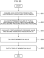
- Fig. 23 is a flowchart illustrating an example of the flow of the processing of outputting data of the moment Mx value at the output section 12 of Fig. 16 .
- the CPU 54 acquires the data outputted from the plural electrostatic capacitance detecting ICs 44.
- This data acquired in step S51 is data of the signals outputted from the sensor portion 18 in correspondence with the first electrodes 34 that are the objects of calculation of displacement ⁇ z in step S52 described hereinafter.
- step S52 on the basis of the data acquired in step S51 and as an example of the "first aggregate pressure detecting position", the CPU 54 selects the second electrode 36-4 (see Fig. 12 ) that is apart in the Y-axis direction from the center of the contacting surface 28, and calculates the displacements ⁇ z for the respective positions of the four first electrodes 34 that partially overlap with the second electrode 36-4.
- the positions of these four first electrodes 34 are an example of the "plurality of pressure detecting positions that are in a vicinity of the first aggregate pressure detecting position”.
- the CPU 54 selects the second electrode 36-6 (see Fig.
- the positions of these four first electrodes 34 are an example of the "plurality of pressure detecting positions that are in a vicinity of the second aggregate pressure detecting position".
- the displacements ⁇ z which are calculated in this way for the respective positions of the first electrodes 34 that partially overlap with the plural second electrodes 36-4,6, are proportional to the pressure values at the respective positions of the first electrodes 34. Accordingly, due to the displacements ⁇ z being calculated for the respective positions of the first electrodes 34, the pressure values at the respective positions of the first electrodes 34 are calculated.
- the pressure values calculated for the respective positions of the first electrodes 34 that partially overlap with the second electrode 36-4 correspond to an example of the "respective pressure values of the plurality of pressure detecting positions that are in a vicinity of the first aggregate pressure detecting position, among the plurality of pressure detecting positions within the contacting surface".
- the pressure values calculated for the respective positions of the first electrodes 34 that partially overlap with the second electrode 36-6 correspond to an example of the "respective pressure values of the plurality of pressure detecting positions that are in a vicinity of the second aggregate pressure detecting position, among the plurality of pressure detecting positions within the contacting surface".
- step S53 the CPU 54 carries out at least any of calculation of a representative value, calculation of the total value and calculation of the average value for the pressure values of the respective positions of the first electrodes 34 that partially overlap with the second electrode 36-4, and makes this calculated value be the first aggregate pressure value. Due thereto, the first aggregate pressure value is calculated for the second electrode 36-4.
- the first aggregate pressure value corresponds to the normal load Fz'.
- step S53 the CPU 54 carries out at least any of calculation of a representative value, calculation of the total value and calculation of the average value for the pressure values of the respective positions of the first electrodes 34 that partially overlap with the second electrode 36-6, and makes this calculated value be the second aggregate pressure value. Due thereto, the second aggregate pressure value is calculated for the second electrode 36-6.
- the second aggregate pressure value corresponds to the normal load Fz'.
- the first aggregate pressure values may be calculated for the second electrodes 36-1,7 also, and at least any of calculation of a representative value, calculation of the total value and calculation of the average value may be carried out for these three first aggregate pressure values, and the calculated value may be made to be the final first aggregate pressure value.
- the first aggregate pressure detecting positions in this case are the respective positions of the second electrodes 36-1,4,7.
- the second aggregate pressure values may be calculated for the second electrodes 36-3,9 also, and at least any of calculation of a representative value, calculation of the total value and calculation of the average value may be carried out for these three second aggregate pressure values, and the calculated value may be made to be the final second aggregate pressure value.
- the second aggregate pressure detecting positions in this case are the respective positions of the second electrodes 36-3,6,9. At this time, it is assumed that the tactile sensor 10 is receiving force from the workpiece W at least at the positions of the second electrodes 36 of these six places.
- step S54 the CPU 54 calculates the difference between a value, which is obtained by multiplying the first aggregate pressure value (the normal load Fz') calculated for the second electrode 36-4 or group of 36-1,4,7 in step S53 by the distance dx, and a value, which is obtained by multiplying the second aggregate pressure value (the normal load Fz') calculated for the second electrode 36-6 or group of 36-3,6,9 in step S53 by the distance dx, and makes this difference be the moment Mx value. Due thereto, the moment Mx value (the magnitude and direction of the moment) is calculated.
- the moment Mx value is an example of the "first moment value".
- step S55 the CPU 54 outputs the data of the moment Mx value that was calculated in step S54 to the controller 104.
- the output section 12 respectively calculates a first aggregate pressure value and a second aggregate pressure value for the second electrodes 36 that are at two places that are apart in the X-axis direction at the contacting surface 28. At this time, it is supposed that the tactile sensor 10 is receiving force from the workpiece W at least at the positions of the second electrodes 36 of these two places. Then, on the basis of the first aggregate pressure value and the second aggregate pressure value, the output section 12 calculates the value of the moment My around the Y-axis direction that is applied to the tactile sensor 10, as the moment My value, and outputs the data of the moment My value. This processing of outputting the data of the moment My value is executed at the CPU 54 of the output section 12 by the following procedures for example.
- Fig. 24 is a flowchart illustrating an example of the flow of the processing of outputting data of the moment My value at the output section 12 of Fig. 16 .
- the CPU 54 acquires the data outputted from the plural electrostatic capacitance detecting ICs 44.
- This data acquired in step S61 is data of the signals outputted from the sensor portion 18 in correspondence with the first electrodes 34 that are the objects of calculation of displacement ⁇ z in step S62 described hereinafter.
- step S62 on the basis of the data acquired in step S61, as an example of the "first aggregate pressure detecting position", the CPU 54 selects the second electrode 36-2 (see Fig. 12 ) that is apart in the X-axis direction from the center of the contacting surface 28, and calculates the displacements ⁇ z for the respective positions of the four first electrodes 34 that partially overlap with the second electrode 36-2.
- the positions of these four first electrodes 34 are an example of the "plurality of pressure detecting positions that are in a vicinity of the first aggregate pressure detecting position”.
- the CPU 54 selects the second electrode 36-8 (see Fig.
- the positions of these four first electrodes 34 are an example of the "plurality of pressure detecting positions that are in a vicinity of the second aggregate pressure detecting position".
- the displacements ⁇ z which are calculated in this way for the respective positions of the first electrodes 34 that partially overlap with the plural second electrodes 36-2,8, are proportional to the pressure values at the respective positions of the first electrodes 34. Accordingly, due to the displacements ⁇ z being calculated for the respective positions of the first electrodes 34, the pressure values at the respective positions of the first electrodes 34 are calculated.
- the pressure values calculated for the respective positions of the first electrodes 34 that partially overlap with the second electrode 36-2 correspond to an example of the "respective pressure values of the plurality of pressure detecting positions that are in a vicinity of the first pressure detecting position, among the plurality of pressure detecting positions within the contacting surface".
- the pressure values calculated for the respective positions of the first electrodes 34 that partially overlap with the second electrode 36-8 correspond to an example of the "respective pressure values of the plurality of pressure detecting positions that are in a vicinity of the second aggregate pressure detecting position, among the plurality of pressure detecting positions within the contacting surface".
- step S63 the CPU 54 carries out at least any of calculation of a representative value, calculation of the total value and calculation of the average value for the respective pressure values of the first electrodes 34 that partially overlap with the second electrode 36-2, and makes this calculated value be the first aggregate pressure value. Due thereto, the first aggregate pressure value is calculated for the second electrode 36-2.
- the first aggregate pressure value corresponds to the normal load Fz'.
- step S63 the CPU 54 carries out at least any of calculation of a representative value, calculation of the total value and calculation of the average value for the respective pressure values of the first electrodes 34 that partially overlap with the second electrode 36-8, and makes this calculated value be the second aggregate pressure value. Due thereto, the second aggregate pressure value is calculated for the second electrode 36-8.
- the second aggregate pressure value corresponds to the normal load Fz'.
- the first aggregate pressure values may be calculated for the second electrodes 36-1,3 also, and at least any of calculation of a representative value, calculation of the total value and calculation of the average value may be carried out for these three first aggregate pressure values, and the calculated value may be made to be the final first aggregate pressure value.
- the first aggregate pressure detecting positions in this case are the respective positions of the second electrodes 36-1,2,3.
- the second aggregate pressure values may be calculated for the second electrodes 36-7,9 also, and at least any of calculation of a representative value, calculation of the total value and calculation of the average value may be carried out for these three second aggregate pressure values, and the calculated value may be made to be the final second aggregate pressure value.
- the second aggregate pressure detecting positions in this case are the respective positions of the second electrodes 36-7,8,9. At this time, it is assumed that the tactile sensor 10 is receiving force from the workpiece W at least at the positions of the second electrodes 36 of these six places.
- step S64 the CPU 54 calculates the difference between a value, which is obtained by multiplying the first aggregate pressure value (the normal load Fz') calculated for the second electrode 36-2 or group of 36-1,2,3 in step S63 by the distance dy, and a value, which is obtained by multiplying the second aggregate pressure value (the normal load Fz') calculated for the second electrode 36-8 or group of 36-7,8,9 in step S63 by the distance dy, and makes this difference be the moment My value. Due thereto, the moment My value (the magnitude and direction of the moment) is calculated.
- the moment My value is an example of the "first moment value".
- step S65 the CPU 54 outputs the data of the moment My value that was calculated in step S64 to the controller 104.
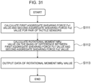
- the output section 12 respectively calculates a first aggregate shearing force value and a second aggregate shearing force value for the second electrodes 36 that are at two places that are apart from the center of the contacting surface 28 in the X-axis direction or the Y-axis direction. Then, on the basis of the first aggregate shearing force value and the second aggregate shearing force value, the output section 12 calculates the value of the moment Mz around the Z-axis direction that is applied to the tactile sensor 10, as the moment Mz value, and outputs the data of the moment Mz value.
- Fig. 25 is a flowchart illustrating an example of the flow of the processing of outputting data of the moment Mz value at the output section 12 of Fig. 16 .
- step S71 the CPU 54 acquires the data outputted from the plural electrostatic capacitance detecting ICs 44.
- This data acquired in step S71 is data of the signals outputted from the sensor portion 18 in correspondence with the first electrodes 34 that are the objects of calculation of displacement ⁇ y in step S72 described hereinafter.
- step S72 on the basis of the data acquired in step S71, as examples of the "first shearing force detecting position" and the "second shearing force detecting position", the CPU 54 calculates the displacements ⁇ y for the respective positions of the second electrodes 36-2,8 that are apart from the center of the contacting surface 28 in the X-axis direction.
- the displacements ⁇ y which are calculated in this way for the respective positions of second electrodes 36-2,8, are proportional to the shearing force Fy values at the respective positions of second electrodes 36-2,8. Therefore, due to the displacements ⁇ y being calculated for the respective positions of second electrodes 36-2,8, the shearing force Fy values at the respective positions of the second electrodes 36-2,8 are calculated.
- the shearing force Fy value that is calculated for the second electrode 36-2 in this way is called the first shearing force Fy value
- the shearing force Fy value that is calculated for the second electrode 36-8 is called the second shearing force Fy value.
- first shearing force Fy value that is calculated for the second electrode 36-2 corresponds to an example of the "first shearing force value that is calculated for the first shearing force detecting position within the contacting surface”.
- second shearing force Fy value that is calculated for the second electrode 36-8 corresponds to an example of the "second shearing force value that is calculated for the second shearing force detecting position within the contacting surface”.
- step S73 the CPU 54 calculates the difference between a value, which is obtained by multiplying the first shearing force Fy value calculated for the second electrode 36-2 in step S72 by the distance dy, and a value, which is obtained by multiplying the second shearing force Fy calculated for the second electrode 36-8 in step S72 by the distance dy, and makes this difference be the moment Mz value. Due thereto, the moment Mz value (the magnitude and direction of the moment) is calculated.
- the moment Mz value is an example of the "second moment value".
- step S74 the CPU 54 outputs the data of the moment Mz value that was calculated in step S73 to the controller 104.
- first shearing force Fy value is calculated for the second electrode 36-2 in above-described step S72
- first shearing force Fy value may be calculated for at least one second electrode 36 among the second electrodes 36-1,2,3.
- second shearing force Fy value is calculated for the second electrode 36-8 in above-described step S72
- the second shearing force Fy value may be calculated for at least one second electrode 36 among the second electrodes 36-7,8,9.
- step S71 the CPU 54 acquires the data outputted from the plural electrostatic capacitance detecting ICs 44.
- This data acquired in step S71 is data of the signals outputted from the sensor portion 18 in correspondence with the first electrodes 34 that are the objects of calculation of displacement ⁇ x in step S72 described hereinafter.
- step S72 on the basis of the data acquired in step S71, as examples of the "first shearing force detecting position" and the "second shearing force detecting position", the CPU 54 calculates the displacements ⁇ x for the respective positions of the second electrodes 36-4,6 that are apart from the center of the contacting surface 28 in the Y-axis direction.
- the displacements ⁇ x which are calculated in this way for the respective positions of second electrodes 36-4,6, are proportional to the shearing force Fx values at the respective positions of second electrodes 36-4,6. Therefore, due to the displacements ⁇ x being calculated for the respective positions of second electrodes 36-4,6, the shearing force Fx values at the respective second electrodes 36-4,6 are calculated.
- first shearing force Fx value that is calculated for the second electrode 36-4 corresponds to an example of the "first shearing force value that is calculated for the first shearing force detecting position within the contacting surface”.
- second shearing force Fx value that is calculated for the second electrode 36-6 corresponds to an example of the "second shearing force value that is calculated for the second shearing force detecting position within the contacting surface”.
- step S73 the CPU 54 calculates the difference between a value, which is obtained by multiplying the first shearing force Fx value calculated for the second electrode 36-4 in step S72 by the distance dx, and a value, which is obtained by multiplying the second shearing force Fx calculated for the second electrode 36-6 in step S72 by the distance dx, and makes this difference be the moment Mz value. Due thereto, the moment Mz value (the magnitude and direction of the moment) is calculated.
- the moment Mz value is an example of the "second moment value".
- step S74 the CPU 54 outputs the data of the moment Mz value that was calculated in step S73 to the controller 104.
- first shearing force Fx value is calculated for the second electrode 36-4 in above-described step S72
- first shearing force Fx value may be calculated for at least one second electrode 36 among the second electrodes 36-1,4,7.
- second shearing force Fx value is calculated for the second electrode 36-6 in above-described step S72
- the second shearing force Fx value may be calculated for at least one second electrode 36 among the second electrodes 36-3,6,9.
- Fig. 26 is a plan view explaining an example of translational force ⁇ Fx in the X-axis direction that is applied to the workpiece W grasped by the pair of grasping portions 114 of Fig. 1 .
- first shearing force Fx1 in the X-axis direction is applied to the first tactile sensor 10 among the pair of tactile sensors 10
- second shearing force Fx2 in the direction opposite the first shearing force Fx1 is applied to the second tactile sensor 10 among the pair of tactile sensors 10.
- the sum of the first shearing force Fx1 and the second shearing force Fx2 which are values to which reference numerals are given, corresponds to the translational force ⁇ Fx in the X-axis direction.
- the output section 12 calculates the sum of the first aggregate shearing force Fx1 value and the second aggregate shearing force Fx2 value, which are calculated for the pair of tactile sensors 10 respectively, as the translational force ⁇ Fx value, and outputs the data of the translational force ⁇ Fx value.
- Fig. 27 is a flowchart illustrating an example of the flow of the processing of outputting data of the translational force ⁇ Fx value at the output section 12 of Fig. 16 .
- the CPU 54 calculates the first aggregate shearing force Fx1 value in the X-axis direction for the first tactile sensor 10.
- the CPU 54 calculates the second aggregate shearing force Fx2 value in the X-axis direction for the second tactile sensor 10.
- the method of calculating the first aggregate shearing force Fx1 value and the second aggregate shearing force Fx2 value in the X-axis direction is as per the above-described method of calculating the aggregate shearing force Fx value (see Fig. 21 ). Due thereto, the first aggregate shearing force Fx1 value and the second aggregate shearing force Fx2 value are calculated for the pair of tactile sensors 10, respectively.
- the first aggregate shearing force Fx1 value and the second aggregate shearing force Fx2 value correspond to an example of the "aggregate shearing force values calculated for the pair of tactile sensors, respectively".
- step S82 the CPU 54 calculates the sum of the first aggregate shearing force Fx1 value and the second aggregate shearing force Fx2 value, which were calculated in step S81, as the translational force ⁇ Fx value.
- step S83 the CPU 54 outputs the data of the translational force ⁇ Fx value that was calculated in step S82 to the controller 104.
- Fig. 28 is a plan view explaining an example of translational force ⁇ Fy in the Y-axis direction that is applied to the workpiece W grasped by the pair of grasping portions 114 of Fig. 1 .
- first shearing force Fy1 in the Y-axis direction is applied to the first tactile sensor 10 among the pair of tactile sensors 10
- second shearing force Fy2 in the direction opposite the first shearing force Fy1 is applied to the second tactile sensor 10 among the pair of tactile sensors 10.
- the sum of the first shearing force Fy1 and the second shearing force Fy2 which are values to which reference numerals are given, corresponds to the translational force ⁇ Fy in the Y-axis direction.
- the output section 12 calculates the sum of the first aggregate shearing force Fy1 value and the second aggregate shearing force Fy2 value, which are calculated for the pair of tactile sensors 10 respectively, as the translational force ⁇ Fy value, and outputs the data of the translational force ⁇ Fy value.
- Fig. 29 is a flowchart illustrating an example of the flow of the processing of outputting data of the translational force ⁇ Fy value at the output section 12 of Fig. 16 .
- the CPU 54 calculates the first aggregate shearing force Fy1 value in the Y-axis direction for the first tactile sensor 10.
- the CPU 54 calculates the second aggregate shearing force Fy2 value in the Y-axis direction for the second tactile sensor 10.
- the method of calculating the first aggregate shearing force Fy1 value and the second aggregate shearing force Fy2 value in the Y-axis direction is as per the above-described method of calculating the aggregate shearing force Fy value (see Fig. 22 ). Due thereto, the first aggregate shearing force Fy1 value and the second aggregate shearing force Fy2 value are calculated for the pair of tactile sensors 10, respectively.
- the first aggregate shearing force Fy1 value and the second aggregate shearing force Fy2 value correspond to an example of the "aggregate shearing force values calculated for the pair of tactile sensors, respectively".
- step S93 the CPU 54 outputs the data of the translational force ⁇ Fy value that was calculated in step S92 to the controller 104.
- the output section 12 calculates the rotational moment MRx value around the X-axis direction on the basis of the difference between the first aggregate shearing force Fy1 value and the second aggregate shearing force Fy2 value, which are values calculated for the pair of tactile sensors 10 respectively and to which reference numerals are given, and outputs the data of the rotational moment MRx value.
- Fig. 30 is a flowchart illustrating an example of the flow of the processing of outputting data of the rotational moment MRx value at the output section 12 of Fig. 16 .
- the CPU 54 calculates the first aggregate shearing force Fy1 value in the Y-axis direction for the first tactile sensor 10.
- the CPU 54 calculates the second aggregate shearing force Fy2 value in the Y-axis direction for the second tactile sensor 10.
- the method of calculating the first aggregate shearing force Fy1 value and the second aggregate shearing force Fy2 value in the Y-axis direction is as per the above-described method of calculating the aggregate shearing force Fy value (see Fig. 22 ). Due thereto, the first aggregate shearing force Fy1 value and the second aggregate shearing force Fy2 value are calculated for the pair of tactile sensors 10, respectively.
- the first aggregate shearing force Fy1 value and the second aggregate shearing force Fy2 value correspond to an example of the "aggregate shearing force values calculated for the pair of tactile sensors, respectively".
- step S102 the CPU 54 calculates the rotational moment MRx value around the X-axis direction on the basis of the difference between the first aggregate shearing force Fy1 value and the second aggregate shearing force Fy2 value that were calculated in step S101.
- step S103 the CPU 54 outputs the data of the rotational moment MRx value that was calculated in step S102 to the controller 104.
- the output section 12 calculates the rotational moment MRy value around the Y-axis direction on the basis of the difference between the first aggregate shearing force Fx1 value and the second aggregate shearing force Fx2 value, which are values calculated for the pair of tactile sensors 10 respectively and to which reference numerals are given, and outputs the data of the rotational moment MRy value.
- Fig. 31 is a flowchart illustrating an example of the flow of the processing of outputting data of the rotational moment MRy value at the output section 12 of Fig. 16 .
- the CPU 54 calculates the first aggregate shearing force Fx1 value in the X-axis direction for the first tactile sensor 10.
- the CPU 54 calculates the second aggregate shearing force Fx2 value in the X-axis direction for the second tactile sensor 10.
- the method of calculating the first aggregate shearing force Fx1 value and the second aggregate shearing force Fx2 value in the X-axis direction is as per the above-described method of calculating the aggregate shearing force Fx value (see Fig. 21 ). Due thereto, the first aggregate shearing force Fx1 value and the second aggregate shearing force Fx2 value are calculated for the pair of tactile sensors 10, respectively.
- the first aggregate shearing force Fx1 value and the second aggregate shearing force Fx2 value correspond to an example of the "aggregate shearing force values calculated for the pair of tactile sensors, respectively".
- step S112 the CPU 54 calculates the rotational moment MRy value around the Y-axis direction on the basis of the difference between the first aggregate shearing force Fx1 value and the second aggregate shearing force Fx2 value that were calculated in step S111.
- step S113 the CPU 54 outputs the data of the rotational moment MRy value that was calculated in step S 112 to the controller 104.
- the plural first electrodes 34 correspond to the one second electrode 36. Therefore, the intervals between the plural first electrodes 34 can be narrowed as compared with a case in which, for example, the plural first electrodes 34 and the plural second electrodes 36 are in a one-to-one correspondence. Due thereto, because the number of the plural first electrodes 34 can be ensured, the resolution of the pressure distribution can be ensured.
- Fig. 32 is a vertical sectional view of the tactile sensor 10 relating to a second embodiment.
- the structure of the second electrode layer 26 is changed as follows with respect to that of the tactile sensor 10 relating to the above-described first embodiment (see Fig. 3 through Fig. 6 ).
- Fig. 33 is a plan view of the second electrode layer 26 of Fig. 32 .
- the second electrode layer 26 is configured by the one second electrode 36 that is a single layer. Namely, the second electrode 36 forms a single island portion.
- the second electrode 36 is formed of a conductive rubber for example. This second electrode 36 is formed in the shape of a flat plate.
- the second electrode 36 may be connected to the ground of the substrate 16, or may be floating with respect to ground.
- Fig. 34 is a plan view illustrating a state in which the second electrode 36 and the elastic layer 22 and the substrate 16 of Fig. 32 are superposed.
- the number of the plural first electrodes 34 is 36, whereas the second electrode 36 forms one island portion. Therefore, in the second embodiment, the number of island portions formed by the second electrode 36 is less than the number of the plural first electrodes 34.
- the second electrode 36 is formed in the shape of a square that is smaller than the contacting surface 28 (see Fig. 32 ).
- This second electrode 36 is a size that overlaps all of the plural first electrodes 34 as viewed in plan view.
- the second electrode 36 is a size such that the first electrodes 34, which are lined-up along the outer peripheral portion of the second electrode 36 among the plural first electrodes 34, and the outer peripheral portion of the second electrode 36 overlap as viewed in a plan view. Due thereto, the first electrodes 34 that are lined-up along the outer peripheral portion of the second electrode 36 partially overlap with the second electrode 36 as viewed in a plan view.
- the plural first electrodes 34 the first electrodes 34 that are positioned at the inner side of the outer peripheral portion of the second electrode 36 entirely overlap the second electrode 36.
- the first electrodes 34 that partially overlap with the second electrode 36 correspond to an example of the "plurality of partially-overlapping electrodes that partially overlap with the second electrode”
- the plural signals outputted from these first electrodes 34 that partially overlap with the second electrode 36 correspond to an example of the "plurality of partially-overlapping electrode signals”.
- the electrostatic capacitance C changes in accordance with this change in the distance d.
- the electrostatic capacitance C changes in accordance with this change in the surface area A.
- the tactile sensor 10 of this structure is manufactured in the same way as the tactile sensor 10 relating to the above-described first embodiment (see Fig. 3 through Fig. 6 ).
- Fig. 35 is a drawing explaining an example of the moment lengths dx, dy at the tactile sensor 10 of Fig. 32 .
- identification numbers 1 ⁇ 28 are shown for the plural first electrodes 34.
- the plural first electrodes 34 are respectively called the first electrodes 34-1-28.
- the moment length dx is the length that is used at the time of calculating the moment Mx around the X-axis direction (see Fig. 11 ).
- the moment length dx corresponds to the distance along the Y-axis direction between the center of the contacting surface 28 and the center of the first electrode 34-4 that is at a position apart from the center of the contacting surface 28 in the Y-axis direction.
- the moment length dy illustrated in Fig. 35 is the length that is used at the time of calculating the moment My around the Y-axis direction (see Fig. 11 ).
- the moment length dy corresponds to the distance along the X-axis direction between the center of the second electrode 36 and the center of the first electrode 34-13 that is at a position apart from the center of the second electrode 36 in the X-axis direction.
- the calculation of the displacements ⁇ x, ⁇ y, ⁇ z is carried out on the basis of an approach similar to that of the case of the first embodiment.
- the hardware structures of the tactile sensor 10, the output section 12 and the controller 104, and the plural modes at the output section 12, are the same as those of the first embodiment.
- the processings of outputting the respective data of the pressure distribution, the grasped position, the grasping force Fz value, the translational force ⁇ Fx value, the translation force ⁇ Fy value, the rotational moment MRx value, and the rotational moment MRy value are the same as in the first embodiment.
- the processings of outputting the respective data of the aggregate shearing force Fx value, the aggregate shearing force Fy value, the moment Mx value, the moment My value, and the moment Mz value differ from the first embodiment.
- the output section 12 calculates one aggregate shearing force Fx value for the entire contacting surface 28, and outputs the data of the aggregate shearing force Fx value.
- This processing of outputting the data of the aggregate shearing force Fx value is executed at the CPU 54 of the output section 12 by the following procedures for example.
- the flow of the processing of outputting the data of the aggregate shearing force Fx value in the second embodiment is described hereinafter with reference to Fig. 21 .
- step S31 the CPU 54 acquires the data outputted from the plural electrostatic capacitance detecting ICs 44.
- This data acquired in step S31 is data of the signals outputted from the sensor portion 18 in correspondence with the first electrodes 34 that are the objects of calculation of displacement ⁇ x in step S32 described hereinafter.
- step S32 on the basis of the data acquired in step S31, the CPU 54 calculates the displacements ⁇ x at the respective positions of the plural first electrodes 34-1-8 that partially overlap with the second electrode 36.
- the plural first electrodes 34 that are the objects of calculation of the displacement ⁇ x may be all of the plural first electrodes 34-1-8, or may be some of the plural first electrodes 34-1-8.
- the CPU 54 calculates the displacements ⁇ x for the respective positions of the plural first electrodes 34-1-8.
- the displacements ⁇ x for the respective positions of the plural first electrodes 34-1-8 are calculated on the basis of some of the plural signals outputted from the sensor portion 18. Note that, in the second embodiment, it is preferable to carry out correction of the displacement ⁇ x by the values of the displacement ⁇ z that are calculated for the first electrodes 34-17-20, 21-24.
- the displacements ⁇ x which are calculated for the respective positions of the plural first electrodes 34-1-8 in this way, are proportional to the shearing force Fx values at the respective positions of the plural first electrodes 34-1-8. Accordingly, due to the displacements ⁇ x being calculated for the respective positions of the plural first electrodes 34-1-8, the shearing force Fx values at the respective positions of the plural first electrodes 34-1-8 are calculated.
- the shearing force Fx values that are calculated for the respective positions of the plural first electrodes 34-1-8 correspond to an example of the "respective shearing force values of the plurality of shearing force detecting positions within the contacting surface".
- step S33 the CPU 54 calculates the aggregate shearing force Fx value by carrying out at least any of calculating a representative value, calculating the total value and calculating the average value for the shearing force Fx values at the respective positions of the plural first electrodes 34-1-8 that were calculated in step S32.
- step S34 the CPU 54 outputs the data of the aggregate shearing force Fx value that was calculated in step S33 to the controller 104.
- This data of the aggregate shearing force Fx value is used in sensing a collision of the workpiece W, detecting the maintaining of contact of the workpiece W held at the robot hand 108 with another object, detecting the position of fitting the workpiece W into the destination of movement, detecting the completion of insertion of the workpiece W into the destination of movement, detecting the completion of pulling of the workpiece W out from the destination of movement, or the like.
- the output section 12 calculates one aggregate shearing force Fy value for the entire contacting surface 28, and outputs the data of the aggregate shearing force Fy value.
- This processing of outputting the data of the aggregate shearing force Fy value is executed at the CPU 54 of the output section 12 by the following procedures for example.
- the flow of the processing of outputting the data of the aggregate shearing force Fy value in the second embodiment is described hereinafter with reference to Fig. 22 .
- step S41 the CPU 54 acquires the data outputted from the plural electrostatic capacitance detecting ICs 44.
- This data acquired in step S41 is data of the signals outputted from the sensor portion 18 in correspondence with the first electrodes 34 that are the objects of calculation of displacement ⁇ y in step S42 described hereinafter.
- step S42 on the basis of the data acquired in step S41, the CPU 54 calculates the displacements ⁇ y at the respective positions of the plural first electrodes 34-9-16 that partially overlap with the second electrode 36.
- the plural first electrodes 34 that are the objects of calculation of the displacement ⁇ y may be all of the plural first electrodes 34-9-16, or may be some of the plural first electrodes 34-9-16.
- the CPU 54 calculates the displacements ⁇ y for the respective positions of the plural first electrodes 34-9-16.
- the displacements ⁇ y for the respective positions of the plural first electrodes 34-9-16 are calculated on the basis of some of the plural signals outputted from the sensor portion 18. Note that, in the second embodiment, it is preferable to carry out correction of the displacement ⁇ y by the values of the displacement ⁇ z calculated for the first electrodes 34-17-25, 26, 21, 20, 27, 28, 24.
- the displacements ⁇ y which are calculated for the respective positions of the plural first electrodes 34-9-16 in this way, are proportional to the shearing force Fy values at the respective positions of the plural first electrodes 34-9-16. Accordingly, due to the displacements ⁇ y being calculated for the respective positions of the plural first electrodes 34-9-16, the shearing force Fy values at the respective positions of the plural first electrodes 34-9-16 are calculated.
- the shearing force Fy values that are calculated for the respective positions of the plural first electrodes 34-9-16 correspond to an example of the "respective shearing force values of the plurality of shearing force detecting positions within the contacting surface".
- step S43 the CPU 54 calculates an aggregate shearing force Fy value by carrying out at least any of calculating a representative value, calculating the total value and calculating the average value of the shearing force Fy values at the respective positions of the plural first electrodes 34-9-16 that were calculated in step S42.
- step S44 the CPU 54 outputs the data of the aggregate shearing force Fy value that was calculated in step S43 to the controller 104.
- This data of the aggregate shearing force Fy value is used in sensing a collision of the workpiece W, detecting the maintaining of contact of the workpiece W held at the robot hand 108 with another object, detecting the position of fitting the workpiece W into the destination of movement, detecting the completion of insertion of the workpiece W into the destination of movement, detecting the completion of pulling of the workpiece W out from the destination of movement, or the like.
- the output section 12 respectively calculates a first aggregate pressure value and a second aggregate pressure value for the first electrodes 34 that are at two places that are apart in the Y-axis direction at the contacting surface 28. Then, on the basis of the first aggregate pressure value and the second aggregate pressure value, the output section 12 calculates the value of the moment Mx around the X-axis direction that is applied to the tactile sensor 10, as the moment Mx value, and outputs the data of the moment Mx value.
- This processing of outputting the data of the moment Mx value is executed at the CPU 54 of the output section 12 by the following procedures for example.
- the flow of the processing of outputting the data of the moment Mx value in the second embodiment is described hereinafter with reference to Fig. 23 .
- step S51 the CPU 54 acquires the data outputted from the plural electrostatic capacitance detecting ICs 44.
- This data acquired in step S51 is data of the signals outputted from the sensor portion 18 in correspondence with the first electrodes 34 that are the objects of calculation of displacement ⁇ z in step S52 described hereinafter.
- step S52 on the basis of the data acquired in step S51, the CPU 54 calculates the displacements ⁇ z for the respective positions of the first electrodes 34-20, 27, 28, 24 and the first electrodes 34-17, 25, 26, 21 that are apart from the center of the contacting surface 28 in the Y-axis direction, as examples of the "plurality of first aggregate pressure detecting positions" and the “plurality of second aggregate pressure detecting positions”.
- the displacements ⁇ z which are calculated in this way for the respective positions of the plural first electrodes 34, are proportional to the pressure values at the respective positions of the plural first electrodes 34. Accordingly, due to the displacements ⁇ z being calculated for the respective positions of the plural first electrodes 34, the pressure values at the respective positions of the plural first electrodes 34 are calculated.
- the pressure values calculated for the respective positions of the first electrodes 34-20, 27, 28, 24 correspond to an example of the "respective pressure values of the plurality of first aggregate pressure detecting positions, among the plurality of pressure detecting positions within the contacting surface". Further, the pressure values calculated for the respective positions of the first electrodes 34-17, 25, 26, 21 correspond to an example of the "respective pressure values of the plurality of second aggregate pressure detecting positions, among the plurality of pressure detecting positions within the contacting surface".
- step S53 the CPU 54 carries out at least any of calculation of a representative value, calculation of the total value and calculation of the average value for the pressure values of the respective positions of the first electrodes 34-20, 27, 28, 24, and makes this calculated value be the first aggregate pressure value. Due thereto, the first aggregate pressure value is calculated for the first electrodes 34-20, 27, 28, 24. The first aggregate pressure value corresponds to the normal load Fz'.
- step S53 the CPU 54 carries out at least any of calculation of a representative value, calculation of the total value and calculation of the average value for the pressure values of the respective positions of the first electrodes 34-17, 25, 26, 21, and makes this calculated value be the second aggregate pressure value. Due thereto, the second aggregate pressure value is calculated for the first electrodes 34-17, 25, 26, 21.
- the second aggregate pressure value corresponds to the normal load Fz'.
- step S54 the CPU 54 calculates the difference between a value, which is obtained by multiplying the first aggregate pressure value (the normal load Fz') calculated for the first electrodes 34-17, 25, 26, 21 in step S53 by the distance dx, and a value, which is obtained by multiplying the second aggregate pressure value (the normal load Fz') calculated for the first electrodes 34-17, 25, 26, 21 in step S53 by the distance dx, and makes this difference be the moment Mx value. Due thereto, the moment Mx value (the magnitude and direction of the moment) is calculated.
- the moment Mx value is an example of the "first moment value".
- step S55 the CPU 54 outputs the data of the moment Mx value that was calculated in step S54 to the controller 104.
- the pressure values at the respective positions of the first electrodes 34-20, 27, 28, 24 are calculated in above-described step S52, the pressure values at the respective positions of any two first electrodes 34 among the first electrodes 34-20, 27, 28, 24 may be calculated.
- the pressure values at the respective positions of the first electrodes 34-17, 25, 26, 21 are calculated in above-described step S52, the pressure values at the respective positions of any two first electrodes 34 among the first electrodes 34-17, 25, 26, 21 may be calculated.
- the output section 12 respectively calculates a first aggregate pressure value and a second aggregate pressure value for the first electrodes 34 that are at two places that are apart in the X-axis direction at the contacting surface 28. Then, on the basis of the first aggregate pressure value and the second aggregate pressure value, the output section 12 calculates the value of the moment My around the Y-axis direction that is applied to the tactile sensor 10, as the moment My value, and outputs the data of the moment My value.
- This processing of outputting the data of the moment Mx value is executed at the CPU 54 of the output section 12 by the following procedures for example.
- the flow of the processing of outputting the data of the moment My value in the second embodiment is described hereinafter with reference to Fig. 24 .
- step S61 the CPU 54 acquires the data outputted from the plural electrostatic capacitance detecting ICs 44.
- This data acquired in step S61 is data of the signals outputted from the sensor portion 18 in correspondence with the first electrodes 34 that are the objects of calculation of displacement ⁇ z in step S62 described hereinafter.
- step S62 on the basis of the data acquired in step S61, the CPU 54 calculates the displacements ⁇ z for the respective positions of the first electrodes 34-17, 18, 19, 20 and the first electrodes 34-21, 22, 23, 24 that are apart from the center of the contacting surface 28 in the X-axis direction, as examples of the "plurality of first aggregate pressure detecting positions" and the “plurality of second aggregate pressure detecting positions”.
- the displacements ⁇ z which are calculated in this way for the respective positions of the plural first electrodes 34, are proportional to the pressure values at the respective positions of the plural first electrodes 34. Accordingly, due to the displacements ⁇ z being calculated for the respective positions of the plural first electrodes 34, the pressure values at the respective positions of the plural first electrodes 34 are calculated.
- the pressure values calculated for the respective positions of the first electrodes 34-17, 18, 19, 20 correspond to an example of the "respective pressure values of the plurality of first aggregate pressure detecting positions, among the plurality of pressure detecting positions within the contacting surface".
- the pressure values calculated for the respective positions of the first electrodes 34-21, 22, 23, 24 correspond to an example of the "respective pressure values of the plurality of second aggregate pressure detecting positions, among the plurality of pressure detecting positions within the contacting surface".
- step S63 the CPU 54 carries out at least any of calculation of a representative value, calculation of the total value and calculation of the average value for the pressure values of the respective positions of the first electrodes 34-17, 18, 19, 20, and makes this calculated value be the first aggregate pressure value. Due thereto, the first aggregate pressure value is calculated for the first electrodes 34-17, 18, 19, 20. The first aggregate pressure value corresponds to the normal load Fz'.
- step S63 the CPU 54 carries out at least any of calculation of a representative value, calculation of the total value and calculation of the average value for the pressure values of the respective positions of the first electrodes 34-21, 22, 23, 24, and makes this calculated value be the second aggregate pressure value. Due thereto, the second aggregate pressure value is calculated for the first electrodes 34-21, 22, 23, 24. The second aggregate pressure value corresponds to the normal load Fz'.
- step S64 the CPU 54 calculates the difference between a value, which is obtained by multiplying the first aggregate pressure value (the normal load Fz') calculated for the first electrodes 34-17, 18, 19, 20 in step S63 by the distance dy, and a value, which is obtained by multiplying the second aggregate pressure value (the normal load Fz') calculated for the first electrodes 34-21, 22, 23, 24 in step S63 by the distance dy, and makes this difference be the moment My value. Due thereto, the moment My value (the magnitude and direction of the moment) is calculated.
- the moment My value is an example of the "first moment value".
- step S65 the CPU 54 outputs the data of the moment My value that was calculated in step S64 to the controller 104.
- the pressure values at the respective positions of the first electrodes 34-17, 18, 19, 20 are calculated in above-described step S62, the pressure values at the respective positions of any two first electrodes 34 among the first electrodes 34-17, 18, 19, 20 may be calculated.
- the pressure values at the respective positions of the first electrodes 34-21, 22, 23, 24 are calculated in above-described step S62, the pressure values at the respective positions of any two first electrodes 34 among the first electrodes 34-21, 22, 23, 24 may be calculated.
- the output section 12 respectively calculates a first shearing force value and a second shearing force value for the first electrodes 34 that are at two places that are apart from the center of the contacting surface 28 in the X-axis direction or the Y-axis direction. Then, on the basis of the first shearing force value and the second shearing force value, the output section 12 calculates the value of the moment Mz around the Z-axis direction that is applied to the tactile sensor 10, as the moment Mz value, and outputs the data of the moment Mz value.
- step S71 the CPU 54 acquires the data outputted from the plural electrostatic capacitance detecting ICs 44.
- This data acquired in step S71 is data of the signals outputted from the sensor portion 18 in correspondence with the first electrodes 34 that are the objects of calculation of displacement ⁇ x in step S72 described hereinafter.
- step S72 on the basis of the data acquired in step S71, as examples of the "first shearing force detecting position" and the "second shearing force detecting position", the CPU 54 calculates the displacements ⁇ x for the respective positions of the first electrodes 34 that are at two places that are apart from one another in the Y-axis direction, among the first electrodes 34-1 ⁇ 4, 5 ⁇ 8.
- the CPU 54 may calculate the displacements ⁇ x for the respective positions of the first electrodes 34-1,4 that are at two places apart from one another in the Y-axis direction among the first electrodes 34-1-4, or may calculate the displacements ⁇ x for the respective positions of the first electrodes 34-5,8 that are at two places apart from one another in the Y-axis direction among the first electrodes 34-5-8.
- the CPU 54 may calculate the displacements ⁇ x for the respective positions of the first electrodes 34-2,3 that are at two places apart from one another in the Y-axis direction among the first electrodes 34-1-4, or may calculate the displacements ⁇ x for the respective positions of the first electrodes 34-6,7 that are at two places apart from one another in the Y-axis direction among the first electrodes 34-5-8.
- the displacements ⁇ x which are calculated in this way for the respective positions of the first electrodes 34 of two places that are apart from one another in the Y-axis direction, are proportional to the shearing force Fx values at the respective positions of the first electrodes 34 of these two places. Accordingly, due to the displacements ⁇ x being calculated for the respective positions of the first electrodes 34 of two places that are apart from one another in the Y-axis direction, the shearing force Fx values at the respective positions of the first electrodes 34 of these two places are calculated.
- the shearing force Fx value that is calculated in this way for one of the first electrodes 34 among the first electrodes 34 at two places is called the first shearing force Fx value
- the shearing force Fx value that is calculated for the other first electrode 34 among the first electrodes 34 at two places is called the second shearing force Fx value.
- step S73 the CPU 54 calculates the difference between the first shearing force Fx value and the second shearing force Fx calculated in step S72, and calculates the moment Mz value (the magnitude and direction of the moment) on the basis of this difference.
- the moment Mz value is an example of the "second moment value”.
- step S74 the CPU 54 outputs the data of the moment Mz value that was calculated in step S73 to the controller 104.
- step S71 the CPU 54 acquires the data outputted from the plural electrostatic capacitance detecting ICs 44.
- This data acquired in step S71 is data of the signals outputted from the sensor portion 18 in correspondence with the first electrodes 34 that are the objects of calculation of displacement ⁇ y in step S72 described hereinafter.
- step S72 on the basis of the data acquired in step S71, as examples of the "first shearing force detecting position" and the "second shearing force detecting position", the CPU 54 calculates the displacements ⁇ y for the respective positions of the first electrodes 34 at two places that are apart from one another in the X-axis direction, among the first electrodes 34-9 ⁇ 12, 13 ⁇ 16.
- the CPU 54 may calculate the displacements ⁇ y for the respective positions of the first electrodes 34-9,12 that are at two places apart from one another in the X-axis direction among the first electrodes 34-9-12, or may calculate the displacements ⁇ y for the respective positions of the first electrodes 34-13,16 that are at two places apart from one another in the X-axis direction among the first electrodes 34-13-16.
- the CPU 54 may calculate the displacements ⁇ y for the respective positions of the first electrodes 34-10,11 that are at two places apart from one another in the X-axis direction among the first electrodes 34-9-12, or may calculate the displacements ⁇ y for the respective positions of the first electrodes 34-14,15 that are at two places apart from one another in the X-axis direction among the first electrodes 34-13-16.
- the displacements ⁇ y which are calculated in this way for the respective positions of the first electrodes 34 that are at two places apart from one another in the X-axis direction, are proportional to the shearing force Fy values at the respective positions the first electrodes 34 at these two places. Accordingly, due to the displacements ⁇ y being calculated for the respective positions of the first electrodes 34 that are at two places apart from one another in the X-axis direction, the shearing force Fy values at the respective positions of the first electrodes 34 at these two places are calculated.
- the shearing force Fy value that is calculated in this way for one of the first electrodes 34 among the first electrodes 34 at the two places is called the first shearing force Fy value
- the shearing force Fy value that is calculated for the other first electrode 34 among the first electrodes 34 at the two places is called the second shearing force Fy value.
- step S73 the CPU 54 calculates the difference between the first shearing force Fy value and the second shearing force Fy calculated in step S72, and calculates the moment Mz value (the magnitude and direction of the moment) on the basis of this difference.
- the moment Mz value is an example of the "second moment value”.
- step S74 the CPU 54 outputs the data of the moment Mz value that was calculated in step S73 to the controller 104.
- Fig. 36 is a vertical sectional view of the tactile sensor 10 relating to a third embodiment.
- the structure of the second electrode layer 26 is changed as follows with respect to that of the tactile sensor 10 relating to the above-described first embodiment (see Fig. 3 through Fig. 6 ).
- Fig. 37 is a plan view of the second electrode layer 26 of Fig. 36 .
- the second electrode layer 26 is configured by the one second electrode 36 that is a single layer.
- the second electrode 36 is formed from a conductive rubber for example.
- This second electrode 36 is formed in the shape of a flat plate.
- the second electrode 36 is formed in a square shape as viewed in plan view.
- the second electrode 36 may be connected to the ground of the substrate 16 (see Fig. 3 ), or may be floating with respect to ground.
- Plural openings 38 are formed in the second electrode 36.
- the plural openings 38 pass-through in the plate thickness direction of the second electrode 36, i.e., the Z-axis direction.
- the plural openings 38 are arrayed in the form of a matrix along the X-Y plane. Namely, the plural openings 38 are arrayed with the X-axis direction being the length direction and the Y-axis direction being the width direction.
- the plural openings 38 are the same shape, and, as an example, the plural openings 38 are formed in square shapes as viewed in plan view.
- the number of the plural openings 38 is less than the number of the above-described, plural first electrodes 34 (see Fig. 4 ).
- the plural openings 38 are arrayed such that there are three thereof in the X-axis direction and three thereof in the Y-axis direction. Namely, the number of the plural openings 38 is nine. These plural openings 38 are arrayed at uniform intervals in the X-axis direction and the Y-axis direction, respectively.
- Fig. 38 is a plan view illustrating a state in which the second electrode 36 and the elastic layer 22 and the substrate 16 of Fig. 36 are superposed.
- the second electrode 36 is a size that overlaps all of the plural first electrodes 34 as viewed in plan view.
- the second electrode 36 is a size that is such that all of the plural first electrodes 34 are contained at the inner side of the outer shape of the second electrode 36 as viewed in plan view.
- the plural openings 38 are respectively formed so as to partially overlap with the respective four first electrodes 34 that are adjacent in the X-axis direction and the Y-axis direction, among the plural first electrodes 34, as viewed in plan view. Specifically, as viewed in plan view, each of the openings 38 is positioned at the central portion of four of the first electrodes 34, and partially overlaps these four first electrodes 34.
- all of the plural first electrodes 34 are contained at the inner side of the outer shape of the second electrode 36 as viewed in a plan view, and further, all of the plural first electrodes 34 partially overlap with the openings 38. All of the plural first electrodes 34 partially overlapping the openings 38 corresponds to all of the plural first electrodes 34 partially overlapping the second electrode 36.
- all of the plural first electrodes 34 correspond to an example of the "plurality of partially-overlapping electrodes that partially overlap with the second electrode"
- the plural signals that are outputted from the plural first electrodes 34 correspond to an example of the "plurality of partially-overlapping electrode signals”.
- the tactile sensor 10 of this structure is manufactured in the same way as the tactile sensor 10 relating to the above-described first embodiment (see Fig. 3 through Fig. 6 ).
- Fig. 39 is a drawing explaining an example of the moment lengths dx, dy at the tactile sensor 10 of Fig. 36 .
- identification numbers 1 ⁇ 9 are shown for the plural openings 38.
- the plural openings 38 are respectively called openings 38-1 ⁇ 9.
- the moment length dx illustrated in Fig. 39 is the length that is used at the time of calculating the moment Mx around the X-axis direction (see Fig. 11 ).
- the moment length dx corresponds to the distance along the Y-axis direction between the center of the contacting surface 28 and the center of the opening 38-3 that is at a position apart from the center of the contacting surface 28 in the Y-axis direction.
- the moment length dy illustrated in Fig. 39 is the length that is used at the time of calculating the moment My around the Y-axis direction (see Fig. 11 ).
- the moment length dy corresponds to the distance along the X-axis direction between the center of the contacting surface 28 and the center of the opening 38-1 that is at a position apart from the center of the contacting surface 28 in the X-axis direction.
- the calculation of the displacements ⁇ x, ⁇ y, ⁇ z is carried out on the basis of an approach similar to that of the case of the first embodiment.
- the hardware structures of the tactile sensors 10, the output section 12 and the controller 104, and the plural modes at the output section 12, are the same as those of the first embodiment.
- the processings of outputting the respective data of the pressure distribution, the grasped position, the grasping force Fz value, the translational force ⁇ Fx value, the translation force ⁇ Fy value, the rotational moment MRx value, and the rotational moment MRy value are the same as in the first embodiment.
- the processings of outputting the respective data of the aggregate shearing force Fx value, the aggregate shearing force Fy value, the moment Mx value, the moment My value, and the moment Mz value differ from the first embodiment.
- the output section 12 calculates one aggregate shearing force Fx value for the entire contacting surface 28, and outputs the data of the aggregate shearing force Fx value.
- This processing of outputting the data of the aggregate shearing force Fx value is executed at the CPU 54 of the output section 12 by the following procedures for example.
- the flow of the processing of outputting the data of the aggregate shearing force Fx value in the third embodiment is described hereinafter with reference to Fig. 21 .
- step S31 the CPU 54 acquires the data outputted from the plural electrostatic capacitance detecting ICs 44.
- This data acquired in step S31 is data of the signals outputted from the sensor portion 18 in correspondence with the first electrodes 34 that are the objects of calculation of displacement ⁇ x in step S32 described hereinafter.
- step S32 on the basis of the data acquired in step S31, the CPU 54 calculates the displacements ⁇ x at the respective positions of the plural openings 38, as an example of the "plurality of shearing force detecting positions".
- the position of the opening 38 is expressed by the position of a specific region of the opening 38, such as the center of or any corner of or the like of the opening 38.
- the calculating of the displacement ⁇ x is carried out on the basis of an approach similar to the explanation of the case in which ⁇ x, ⁇ y, ⁇ z t- 0 in the first embodiment, by using all or some of the signals corresponding to the four first electrodes 34 that partially overlap with the one opening 38.
- the signals corresponding to at least two electrodes whose positions in the x direction differ, among the four first electrodes 34 that overlap the one opening 38, are used.
- the plural openings 38 that are the objects of calculation of the displacement ⁇ x may be all of the openings 38, or may be some of the openings 38.
- all of the plural signals outputted from the sensor portion 18 may be used, or some of the plural signals may be used.
- the displacements ⁇ x which are calculated for the respective positions of the plural openings 38 in this way, are proportional to the shearing force Fx values at the respective positions of the plural openings 38. Accordingly, due to the displacements ⁇ x being calculated for the respective positions of the plural openings 38, the shearing force Fx values at the respective positions of the plural openings 38 are calculated.
- the shearing force Fx values that are calculated for the respective positions of the plural openings 38 correspond to an example of the "respective shearing force values of the plurality of shearing force detecting positions within the contacting surface".
- step S33 the CPU 54 calculates an aggregate shearing force Fx value by carrying out at least any of calculating a representative value, calculating the total value and calculating the average value for the shearing force Fx values at the respective positions of the plural openings 38 that were calculated in step S32.
- step S34 the CPU 54 outputs the data of the aggregate shearing force Fx value that was calculated in step S33 to the controller 104.
- This data of the aggregate shearing force Fx value is used in sensing a collision of the workpiece W, detecting the maintaining of contact of the workpiece W held at the robot hand 108 with another object, detecting the position of fitting the workpiece W into the destination of movement, detecting the completion of insertion of the workpiece W into the destination of movement, detecting the completion of pulling of the workpiece W out from the destination of movement, or the like.
- the output section 12 calculates one aggregate shearing force Fy value for the entire contacting surface 28, and outputs the data of the aggregate shearing force Fy value.
- This processing of outputting the data of the aggregate shearing force Fy value is executed at the CPU 54 of the output section 12 by the following procedures for example.
- the flow of the processing of outputting the data of the aggregate shearing force Fy value in the third embodiment is described hereinafter with reference to Fig. 22 .
- step S41 the CPU 54 acquires the data outputted from the plural electrostatic capacitance detecting ICs 44.
- This data acquired in step S41 is data of the signals outputted from the sensor portion 18 in correspondence with the first electrodes 34 that are the objects of calculation of displacement ⁇ y in step S42 described hereinafter.
- step S42 on the basis of the data acquired in step S41, the CPU 54 calculates the displacements ⁇ y at the respective positions of the plural openings 38, as an example of the "plurality of shearing force detecting positions".
- the position of the opening 38 is expressed by the position of a specific region of the opening 38, such as the center of or any corner of or the like of the opening 38.
- the calculating of the displacement ⁇ y is carried out on the basis of an approach similar to the explanation of the case in which ⁇ x, ⁇ y, ⁇ z t- 0 in the first embodiment, by using all or some of the signals corresponding to the four first electrodes 34 that partially overlap with the one opening 38.
- the signals corresponding to at least two electrodes whose positions in the y direction differ, among the four first electrodes 34 that overlap the one opening 38, are used.
- the plural openings 38 that are the object of calculation of the displacement ⁇ y may be all of the openings 38, or may be some of the openings 38.
- all of the plural signals outputted from the sensor portion 18 may be used, or some of the plural signals may be used.
- the displacements ⁇ y which are calculated for the respective positions of the plural openings 38 in this way, are proportional to the shearing force Fy values at the respective positions of the plural openings 38. Accordingly, due to the displacements ⁇ y being calculated for the respective positions of the plural openings 38, the shearing force Fy values at the respective positions of the plural openings 38 are calculated.
- the shearing force Fy values that are calculated for the respective positions of the plural openings 38 correspond to an example of the "respective shearing force values of the plurality of shearing force detecting positions within the contacting surface".
- step S43 the CPU 54 calculates the aggregate shearing force Fy value by carrying out at least any of calculating a representative value, calculating the total value and calculating the average value for the shearing force Fy values at the respective positions of the plural openings 38 that were calculated in step S42.
- step S44 the CPU 54 outputs the data of the aggregate shearing force Fy value that was calculated in step S43 to the controller 104.
- This data of the aggregate shearing force Fy value is used in sensing a collision of the workpiece W, detecting the maintaining of contact of the workpiece W held at the robot hand 108 with another object, detecting the position of fitting the workpiece W into the destination of movement, detecting the completion of insertion of the workpiece W into the destination of movement, detecting the completion of pulling of the workpiece W out from the destination of movement, or the like.
- the output section 12 respectively calculates a first aggregate pressure value and a second aggregate pressure value for the openings 38 that are at two places that are apart in the Y-axis direction at the contacting surface 28. At this time, it is assumed that the tactile sensor 10 is receiving force from the workpiece W at least at the positions of the openings 38 of these two places. Then, on the basis of the first aggregate pressure value and the second aggregate pressure value, the output section 12 calculates the value of the moment Mx around the X-axis direction that is applied to the tactile sensor 10, as the moment Mx value, and outputs the data of the moment Mx value.
- This processing of outputting the data of the moment Mx value is executed at the CPU 54 of the output section 12 by the following procedures for example.
- the flow of the processing of outputting the data of the moment Mx value in the third embodiment is described hereinafter with reference to Fig. 23 .
- step S51 the CPU 54 acquires the data outputted from the plural electrostatic capacitance detecting ICs 44.
- This data acquired in step S51 is data of the signals outputted from the sensor portion 18 in correspondence with the first electrodes 34 that are the objects of calculation of displacement ⁇ z in step S52 described hereinafter.
- step S52 on the basis of the data acquired in step S51 and as an example of the "plurality of first aggregate pressure detecting positions", the opening 38-4 (see Fig. 39 ), which is apart from the center of the contacting surface 28 in the Y-axis direction, is selected, and the CPU 54 calculates the displacements ⁇ z for the respective positions of the four first electrodes 34 that partially overlap with the opening 38-4.
- the positions of these four first electrodes 34 are an example of the "plurality of pressure detecting positions that are in a vicinity of the first aggregate pressure detecting position”.
- the opening 38-6 see Fig.
- the positions of these four first electrodes 34 are an example of the "plurality of pressure detecting positions that are in a vicinity of the second aggregate pressure detecting position".
- the displacements ⁇ z which are calculated in this way for the respective positions of the first electrodes 34 that partially overlap with the plural openings 38-4,6, are proportional to the pressure values at the respective positions of the first electrodes 34. Accordingly, due to the displacements ⁇ z being calculated for the respective positions of the first electrodes 34, the pressure values at the respective positions of the first electrodes 34 are calculated.
- the pressure values calculated for the respective positions of the first electrodes 34 that partially overlap with the opening 38-4 correspond to an example of the "respective pressure values of the plurality of pressure detecting positions that are in a vicinity of the first aggregate pressure detecting position, among the plurality of pressure detecting positions within the contacting surface".
- the pressure values calculated for the respective positions of the first electrodes 34 that partially overlap with the opening 38-6 correspond to an example of the "respective pressure values of the plurality of pressure detecting positions that are in a vicinity of the second aggregate pressure detecting position, among the plurality of pressure detecting positions within the contacting surface".
- step S53 the CPU 54 carries out at least any of calculation of a representative value, calculation of the total value and calculation of the average value for the pressure values of the respective positions of the first electrodes 34 that partially overlap with the opening 38-4, and makes this calculated value be the first aggregate pressure value. Due thereto, the first aggregate pressure value is calculated for the opening 38-4.
- the first aggregate pressure value corresponds to the normal load Fz'.
- step S53 the CPU 54 carries out at least any of calculation of a representative value, calculation of the total value and calculation of the average value for the pressure values of the respective positions of the first electrodes 34 that partially overlap with the opening 38-6, and makes this calculated value be the second aggregate pressure value. Due thereto, the second aggregate pressure value is calculated for the opening 38-6.
- the second aggregate pressure value corresponds to the normal load Fz'.
- the first aggregate pressure values may be calculated for the openings 38-1,7 also, and at least any of calculation of a representative value, calculation of the total value and calculation of the average value may be carried out for these three first aggregate pressure values, and the calculated value may be made to be the final first aggregate pressure value.
- the first aggregate pressure detecting positions in this case are the respective positions of the openings 38-1,4,7.
- the second aggregate pressure values may be calculated for the openings 38-3,9 also, and at least any of calculation of a representative value, calculation of the total value and calculation of the average value may be carried out for these three second aggregate pressure values, and the calculated value may be made to be the final second aggregate pressure value.
- the second aggregate pressure detecting positions in this case are the respective positions of the openings 38-3,6,9. At this time, it is assumed that the tactile sensor 10 is receiving force from the workpiece W at least at the positions of the openings 38 of these six places.
- step S54 the CPU 54 calculates the difference between a value, which is obtained by multiplying the first aggregate pressure value (the normal load Fz') calculated for the opening 38-4 or group of 38-1,4,7 in step S53 by the distance dx, and a value, which is obtained by multiplying the second aggregate pressure value (the normal load Fz') calculated for the opening 38-6 or group of 38-3,6,9 in step S53 by the distance dx, and makes this difference be the moment Mx value. Due thereto, the moment Mx value (the magnitude and direction of the moment) is calculated.
- the moment Mx value is an example of the "first moment value".
- step S55 the CPU 54 outputs the data of the moment Mx value that was calculated in step S54 to the controller 104.
- the output section 12 respectively calculates a first aggregate pressure value and a second aggregate pressure value for the openings 38 that are at two places that are apart in the X-axis direction at the contacting surface 28. At this time, it is assumed that the tactile sensor 10 is receiving force from the workpiece W at least at the positions of the openings 38 of these two places. Then, on the basis of the first aggregate pressure value and the second aggregate pressure value, the output section 12 calculates the value of the moment My around the Y-axis direction that is applied to the tactile sensor 10, as the moment My value, and outputs the data of the moment My value.
- This processing of outputting the data of the moment My value is executed at the CPU 54 of the output section 12 by the following procedures for example.
- the flow of the processing of outputting the data of the moment My value in the third embodiment is described hereinafter with reference to Fig. 24 .
- step S61 the CPU 54 acquires the data outputted from the plural electrostatic capacitance detecting ICs 44.
- This data acquired in step S61 is data of the signals outputted from the sensor portion 18 in correspondence with the first electrodes 34 that are the objects of calculation of displacement ⁇ x in step S62 described hereinafter.
- step S62 on the basis of the data acquired in step S61 and as an example of the "plurality of first aggregate pressure detecting positions", the opening 382, which is apart from the center of the contacting surface 28 in the X-axis direction, is selected, and the CPU 54 calculates the displacements ⁇ z for the respective positions of the four first electrodes 34 that partially overlap with the opening 38-2.
- the positions of these four first electrodes 34 are an example of the "plurality of pressure detecting positions that are in a vicinity of the first aggregate pressure detecting position”.
- the opening 38-8 see Fig.
- the positions of these four first electrodes 34 are an example of the "plurality of pressure detecting positions that are in a vicinity of the second aggregate pressure detecting position".
- the displacements ⁇ z which are calculated in this way for the respective positions of the first electrodes 34 that partially overlap with the plural openings 38-2,8, are proportional to the pressure values at the respective positions of the first electrodes 34. Accordingly, due to the displacements ⁇ z being calculated for the respective positions of the first electrodes 34, the pressure values at the respective positions of the first electrodes 34 are calculated.
- the pressure values calculated for the respective positions of the first electrodes 34 that partially overlap with the opening 38-2 correspond to an example of the "respective pressure values of the plurality of pressure detecting positions that are in a vicinity of the first pressure detecting position, among the plurality of pressure detecting positions within the contacting surface".
- the pressure values calculated for the respective positions of the first electrodes 34 that partially overlap with the opening 38-8 correspond to an example of the "respective pressure values of the plurality of pressure detecting positions that are in a vicinity of the second aggregate pressure detecting position, among the plurality of pressure detecting positions within the contacting surface".
- step S63 the CPU 54 carries out at least any of calculation of a representative value, calculation of the total value and calculation of the average value for the respective pressure values of the first electrodes 34 that partially overlap with the opening 38-2, and makes this calculated value be the first aggregate pressure value. Due thereto, the first aggregate pressure value is calculated for the openings 38-1,2,3. The first aggregate pressure value corresponds to the normal load Fz'.
- step S63 the CPU 54 carries out at least any of calculation of a representative value, calculation of the total value and calculation of the average value for the respective pressure values of the first electrodes 34 that partially overlap with the opening 38-8, and makes this calculated value be the second aggregate pressure value. Due thereto, the second aggregate pressure value is calculated for the opening 38-8.
- the second aggregate pressure value corresponds to the normal load Fz'.
- the first aggregate pressure values may be calculated for the openings 38-1,3 also, and at least any of calculation of a representative value, calculation of the total value and calculation of the average value may be carried out for these three first aggregate pressure values, and the calculated value may be made to be the final first aggregate pressure value.
- the first aggregate pressure detecting positions in this case are the respective positions of the openings 38-1,2,3.
- the second aggregate pressure values may be calculated for the openings 38-7,9 also, and at least any of calculation of a representative value, calculation of the total value and calculation of the average value may be carried out for these three second aggregate pressure values, and the calculated value may be made to be the final second aggregate pressure value.
- the second aggregate pressure detecting positions in this case are the respective positions of the openings 38-7,8,9. At this time, it is assumed that the tactile sensor 10 is receiving force from the workpiece W at least at the positions of the openings 38 of these six places.
- step S64 the CPU 54 calculates the difference between a value, which is obtained by multiplying the first aggregate pressure value (the normal load Fz') calculated for the opening 38-4 or group of 38-1,2,3 in step S63 by the distance dy, and a value, which is obtained by multiplying the second aggregate pressure value (the normal load Fz') calculated for the opening 38-8 or group of 38-7,8,9 in step S63 by the distance dy, and makes this difference be the moment My value. Due thereto, the moment My value (the magnitude and direction of the moment) is calculated.
- the moment My value is an example of the "first moment value".
- step S65 the CPU 54 outputs the data of the moment My value that was calculated in step S64 to the controller 104.
- the output section 12 respectively calculates a first aggregate shearing force value and a second aggregate shearing force value for the openings 38 that are at two places that are apart from the center of the contacting surface 28 in the X-axis direction or the Y-axis direction. Then, on the basis of the first aggregate shearing force value and the second aggregate shearing force value, the output section 12 calculates the value of the moment Mz around the Z-axis direction that is applied to the tactile sensor 10, as the moment Mz value, and outputs the data of the moment Mz value.
- step S71 the CPU 54 acquires the data outputted from the plural electrostatic capacitance detecting ICs 44.
- This data acquired in step S71 is data of the signals outputted from the sensor portion 18 in correspondence with the first electrodes 34 that are the objects of calculation of displacement ⁇ y in step S72 described hereinafter.
- step S72 on the basis of the data acquired in step S71, as examples of the "first shearing force detecting position" and the “second shearing force detecting position", the CPU 54 calculates the displacements ⁇ y for the respective positions of the openings 38-2,8 that are apart from the center of the contacting surface 28 in the X-axis direction.
- the displacements ⁇ y which are calculated in this way for the respective positions of the openings 38-2,8, are proportional to the shearing force Fy values at the respective positions of the openings 38. Therefore, due to the displacements ⁇ y being calculated for the respective positions of the openings 38-2,8, the shearing force Fy values at the respective positions of the openings 38-2,8 are calculated.
- the shearing force Fy value that is calculated for the opening 38-2 in this way is called the first shearing force Fy value
- the shearing force Fy value that is calculated for the opening 38-8 is called the second shearing force Fy value.
- first shearing force Fy value that is calculated for the opening 38-2 corresponds to an example of the "first shearing force value that is calculated for the first shearing force detecting position within the contacting surface”.
- second shearing force Fy value that is calculated for the opening 38-8 corresponds to an example of the "second shearing force value that is calculated for the second shearing force detecting position within the contacting surface”.
- step S73 the CPU 54 calculates the difference between a value, which is obtained by multiplying the first shearing force Fy value calculated for the opening 38-2 in step S72 by the distance dy, and a value, which is obtained by multiplying the second shearing force Fy calculated for the opening 38-8 in step S72 by the distance dy, and makes this difference be the moment Mz value. Due thereto, the moment Mz value (the magnitude and direction of the moment) is calculated.
- the moment Mz value is an example of the "second moment value".
- step S74 the CPU 54 outputs the data of the moment Mz value that was calculated in step S73 to the controller 104.
- first shearing force Fy value is calculated for the opening 38-2 in above-described step S72
- first shearing force Fy value may be calculated for at least one opening 38 among the openings 38-1,2,3.
- second shearing force Fy value is calculated for the opening 38-8 in above-described step S72
- the second shearing force Fy value may be calculated for at least one opening 38 among the openings 38-7,8,9.
- step S71 the CPU 54 acquires the data outputted from the plural electrostatic capacitance detecting ICs 44.
- This data acquired in step S71 is data of the signals outputted from the sensor portion 18 in correspondence with the first electrodes 34 that are the objects of calculation of displacement ⁇ x in step S72 described hereinafter.
- step S72 on the basis of the data acquired in step S71, as examples of the "first shearing force detecting position" and the “second shearing force detecting position", the CPU 54 calculates the displacements ⁇ x for the respective positions of the openings 38-4,6 that are apart from the center of the contacting surface 28 in the Y-axis direction.
- the displacements ⁇ x which are calculated in this way for the respective positions of the openings 38-4,6, are proportional to the shearing force Fx values at the respective positions of the openings 38. Therefore, due to the displacements ⁇ x being calculated for the respective positions of the openings 38-4,6, the shearing force Fx values at the respective positions of the openings 38-4,6 are calculated.
- first shearing force Fx value that is calculated for the opening 38-4 corresponds to an example of the "first shearing force value that is calculated for the first shearing force detecting position within the contacting surface”.
- second shearing force Fx value that is calculated for the opening 38-6 corresponds to an example of the "second shearing force value that is calculated for the second shearing force detecting position within the contacting surface”.
- step S73 the CPU 54 calculates the difference between a value, which is obtained by multiplying the first shearing force Fx value calculated for the opening 38-4 in step S72 by the distance dx, and a value, which is obtained by multiplying the second shearing force Fx calculated for the opening 38-8 in step S72 by the distance dx, and makes this difference be the moment Mz value. Due thereto, the moment Mz value (the magnitude and direction of the moment) is calculated.
- the moment Mz value is an example of the "second moment value".
- step S74 the CPU 54 outputs the data of the moment Mz value that was calculated in step S73 to the controller 104.
- first shearing force Fx value is calculated for the opening 38-4 in above-described step S72
- first shearing force Fx value may be calculated for at least one opening 38 among the openings 38-1,4,7.
- second shearing force Fx value is calculated for the opening 38-6 in above-described step S72
- the second shearing force Fx value may be calculated for at least an opening 38 among the openings 38-3,6,9.
- the output section 12 calculates the one aggregate shearing force Fy value for the entire contacting surface 28, and outputs the data of the aggregate shearing force Fy value. Accordingly, because there is no need to calculate the aggregate shearing force Fy value at the controller 104, the burden on the controller 104 can be reduced.
- the amount of data communicated between the output section 12 and the controller 104 can be reduced by an amount corresponding to the aggregating of the shearing force Fx values. Due thereto, the response speeds of the output section 12 and the controller 104 can be improved, and therefore, tactile information that is useful in controlling the robot 102 that has the pair of grasping portions 114 can be provided efficiently to the controller 104 that controls the robot 102.
- the output section 12 calculates the shearing force Fx values of the respective positions of the plural openings 38 within the contacting surface 28, on the basis of all or some of the plural signals outputted from the sensor portion 18. Then, the output section 12 calculates the aggregate shearing force Fx value by carrying out at least any of calculating a representative value, calculating the total value and calculating the average value for the shearing force Fx values of the respective positions of the plural openings 38.
- the aggregate shearing force Fx value that more accurately expresses the shearing force Fx value of the entire contacting surface 28 can be outputted.
- the output section 12 calculates the shearing force Fy values of the respective positions of the plural openings 38 within the contacting surface 28, on the basis of all or some of the plural signals outputted from the sensor portion 18. Then, the output section 12 calculates the aggregate shearing force Fy value by carrying out at least any of calculating a representative value, calculating the total value and calculating the average value for the shearing force Fy values of the respective positions of the plural openings 38.
- the aggregate shearing force Fy value that more accurately expresses the shearing force Fy value of the entire contacting surface 28 can be outputted.
- the output section 12 calculates a first aggregate pressure value and a second aggregate pressure value respectively for the openings 38 that are at two places that are apart in the Y-axis direction at the contacting surface 28. Then, on the basis of the first aggregate pressure value and the second aggregate pressure value, the output section 12 calculates, as the moment Mx value, the value of the moment Mx around the X-axis direction that is applied to the tactile sensor 10, and outputs the data of the moment Mx value. Accordingly, because there is no need for the moment Mx value to be calculated at the controller 104, the burden on the controller 104 can be reduced.
- the output section 12 calculates a first aggregate pressure value and a second aggregate pressure value respectively for the openings 38 that are at two places that are apart in the X-axis direction at the contacting surface 28. Then, on the basis of the first aggregate pressure value and the second aggregate pressure value, the output section 12 calculates, as the moment My value, the value of the moment My around the Y-axis direction that is applied to the tactile sensor 10, and outputs the data of the moment My value. Accordingly, because there is no need for the moment My value to be calculated at the controller 104, the burden on the controller 104 can be reduced.
- the output section 12 calculates a first shearing force Fy value and a second shearing force Fy value respectively for the openings 38 at two places that are apart in the X-axis direction at the contacting surface 28. Then, on the basis of the first shearing force Fy value and the second shearing force Fy value, the output section 12 calculates, as the moment Mz value, the value of the moment Mz around the Z-axis direction that is applied to the tactile sensor 10, and outputs the data of the moment Mz value. Accordingly, because there is no need for the moment Mz value to be calculated at the controller 104, the burden on the controller 104 can be reduced.
- the output section 12 calculates a first shearing force Fx value and a second shearing force Fx value respectively for the openings 38 at two places that are apart in the Y-axis direction at the contacting surface 28. Then, on the basis of the first shearing force Fx value and the second shearing force Fx value, the output section 12 calculates, as the moment Mz value, the value of the moment Mz around the Z-axis direction that is applied to the tactile sensor 10, and outputs the data of the moment Mz value. Accordingly, because there is no need for the moment Mz value to be calculated at the controller 104, the burden on the controller 104 can be reduced.
- the second electrode layer 26 is configured by the one second electrode 36 that is a single layer. Accordingly, the structure and the manufacturing processes of the tactile sensor 10 can be simplified.
- the pressures at the respective positions of the plural first electrodes 34 can be detected by detecting the electrostatic capacitances that change in accordance with the distances between the first electrodes 34 and the openings 38.
- the respective openings 38 partially overlap with the respective, four first electrodes that are adjacent in the X-axis direction and the Y-axis direction. Therefore, by detecting the electrostatic capacitances that change in accordance with the surface areas over which the four first electrodes 34 and the plural openings 38 overlap one another, shearing forces also can be detected at the positions of the respective openings 38.
- the plural first electrodes 34 correspond to the one opening 38. Therefore, the intervals between the plural first electrodes 34 can be narrowed as compared with a case in which, for example, the plural first electrodes 34 and the plural openings 38 are in a one-to-one correspondence. Due thereto, because the number of the plural first electrodes 34 can be ensured, the resolution of the pressure distribution can be ensured.
- the second electrode 36 is a single structure having the plural openings 38, as compared with a case in which the second electrode 36 is configured by plural members for example, the manufacturing efficiency can be improved, and the number of parts can be reduced.
- Fig. 40 is a vertical sectional view of the tactile sensor 10 relating to a fourth embodiment.
- the structure of the second electrode layer 26 is changed as follows with respect to that of the tactile sensor 10 relating to the above-described first embodiment (see Fig. 3 through Fig. 6 ).
- Fig. 41 is a plan view of the second electrode layer 26 of Fig. 40 .
- the second electrode layer 26 is configured by the one second electrode 36 that is a single layer.
- the second electrode 36 is formed in the shape of a flat plate.
- the second electrode 36 may be connected to the ground of the substrate 16, or may be floating with respect to ground.
- the second electrode 36 is formed of a conductive rubber for example.
- One opening 38 is formed in the second electrode 36.
- the opening 38 is formed in the central portion of the second electrode 36.
- the second electrode 36 is formed in a square shape as viewed in plan view, and the opening 38 also is formed in a square shape as viewed in plan view.
- Fig. 42 is a plan view illustrating a state in which the second electrode 36 and the elastic layer 22 and the substrate 16 of Fig. 40 are superposed.
- the number of the plural first electrodes 34 is 36, whereas the one opening 38 is formed in the second electrode 36. Therefore, in the fourth embodiment, the number of the openings 38 formed in the second electrode 36 is less than the number of the plural first electrodes 34.
- the second electrode 36 is a size that overlaps all of the plural first electrodes 34 as viewed in plan view. Specifically, the second electrode 36 is a size that is such that all of the plural first electrodes 34 are contained at the inner side of the outer shape of the second electrode 36 as viewed in plan view.
- the opening 38 is formed in the shape of a square that is smaller than the minimum square that contains all of the central, four first electrodes 34 that are adjacent in the X-axis direction and the Y-axis direction, as viewed in plan view.
- the opening 38 is positioned at the central portion of the central, four first electrodes 34 as viewed in plan view, and partially overlaps these four first electrodes 34. Due thereto, among the plural first electrodes 34, the central, four first electrodes 34 partially overlap with the second electrode 36 as viewed in plan view. Among the plural first electrodes 34, the first electrodes 34 that are other than the central, four first electrodes 34 completely overlap the second electrode 36.
- the central, four first electrodes 34 among the plural first electrodes 34 correspond to an example of the "plurality of partially-overlapping electrodes that partially overlap with the second electrode", and the plural signals outputted from these central, four first electrodes correspond to an example of the "plurality of partially-overlapping electrode signals”.
- the tactile sensor 10 of this structure is manufactured in the same way as the tactile sensor 10 relating to the above-described first embodiment (see Fig. 3 through Fig. 6 ).
- the calculation of the displacements ⁇ x, ⁇ y, ⁇ z is carried out on the basis of an approach similar to that of the case of the first embodiment.
- the hardware structures of the tactile sensors 10, the output section 12 and the controller 104, and the plural modes at the output section 12, are the same as those of the first embodiment.
- the processings of outputting the respective data of the pressure distribution, the grasped position, the grasping force Fz value, the translational force ⁇ Fx value, the translation force ⁇ Fy value, the rotational moment MRx value, and the rotational moment MRy value are the same as in the first embodiment.
- the processings of outputting the respective data of the aggregate shearing force Fx value and the aggregate shearing force Fy value differ from the first embodiment.
- the output section 12 calculates one aggregate shearing force Fx value for the entire contacting surface 28, and outputs the data of the aggregate shearing force Fx value.
- This processing of outputting the data of the aggregate shearing force Fx value is executed at the CPU 54 of the output section 12 by the following procedures for example.
- the flow of the processing of outputting the data of the aggregate shearing force Fx value in the fourth embodiment is described with reference to Fig. 21 .
- step S31 the CPU 54 acquires the data outputted from the plural electrostatic capacitance detecting ICs 44.
- This data acquired in step S31 is data of the signals outputted from the sensor portion 18 in correspondence with the first electrodes 34 that are the objects of calculation of displacement ⁇ x in step S32 described hereinafter.
- step S32 on the basis of the data acquired in step S31, the CPU 54 calculates the displacement ⁇ x for the position of the opening 38.
- the calculating of the displacement ⁇ x is carried out in accordance with the explanation of the case in which ⁇ x, ⁇ y, ⁇ z ⁇ 0 in the first embodiment, by using all or some of the signals corresponding to the four first electrodes 34 that partially overlap with the one opening 38. In a case of using some of the signals, the signals corresponding to at least two electrodes whose positions in the x direction differ, among the four first electrodes 34 that overlap the one opening 38, are used.
- the displacement ⁇ x for the position of the opening 38 is calculated on the basis of some of the plural signals outputted from the sensor portion 18.
- the displacement ⁇ x which is calculated for the position of the opening 38 in this way, is proportional to the shearing force Fx value at the position of the opening 38. Accordingly, due to the displacement ⁇ x being calculated for the position of the opening 38, the shearing force Fx value at the position of the opening 38 is calculated.
- step S33 the CPU 54 makes the shearing force Fx value at the position of the opening 38 that was calculated in step S32 be the one aggregate shearing force Fx value calculated for the entire contacting surface 28. Due thereto, the one aggregate shearing force Fx value is calculated.
- step S34 the CPU 54 outputs the data of the aggregate shearing force Fx value that was calculated in step S33 to the controller 104.
- This data of the aggregate shearing force Fx value is used in sensing a collision of the workpiece W, detecting the maintaining of contact of the workpiece W held at the robot hand 108 with another object, detecting the position of fitting the workpiece W into the destination of movement, detecting the completion of insertion of the workpiece W into the destination of movement, detecting the completion of pulling of the workpiece W out from the destination of movement, or the like.
- the output section 12 calculates one aggregate shearing force Fy value for the entire contacting surface 28, and outputs the data of the aggregate shearing force Fy value.
- This processing of outputting the data of the aggregate shearing force Fy value is executed at the CPU 54 of the output section 12 by the following procedures for example.
- the flow of the processing of outputting the data of the aggregate shearing force Fy value in the fourth embodiment is described with reference to Fig. 22 .
- step S41 the CPU 54 acquires the data outputted from the plural electrostatic capacitance detecting ICs 44.
- This data acquired in step S41 is data that is needed in order to calculate the displacement ⁇ y in step S42 that is described hereinafter, and is data of the signals outputted from the sensor portion 18 in correspondence with the respective, four first electrodes 34 at the center.
- step S42 on the basis of the data acquired in step S41, the CPU 54 calculates the displacement ⁇ y at the position of the opening 38.
- the calculating of the displacement ⁇ y is carried out in accordance with the explanation of the case in which ⁇ x, ⁇ y, ⁇ z ⁇ 0 in the first embodiment, by using all or some of the signals corresponding to the four first electrodes 34 that partially overlap with the one opening 38. In a case of using some of the signals, the signals corresponding to at least two electrodes whose positions in the y direction differ, among the four first electrodes 34 that overlap the one opening 38, are used.
- the displacement ⁇ y for the position of the opening 38 is calculated on the basis of some of the plural signals outputted from the sensor portion 18.
- the displacement ⁇ y which is calculated for the position of the opening 38 in this way, is proportional to the shearing force Fy value at the position of the opening 38. Accordingly, due to the displacement ⁇ y being calculated for the position of the opening 38, the shearing force Fy value at the position of the opening 38 is calculated.
- step S43 the CPU 54 makes the shearing force Fy value at the position of the opening 38 that was calculated in step S42 be the one aggregate shearing force Fy value calculated for the entire contacting surface 28. Due thereto, the one aggregate shearing force Fy value is calculated.
- step S44 the CPU 54 outputs the data of the aggregate shearing force Fy value that was calculated in step S43 to the controller 104.
- This data of the aggregate shearing force Fy value is used in sensing a collision of the workpiece W, detecting the maintaining of contact of the workpiece W held at the robot hand 108 with another object, detecting the position of fitting the workpiece W into the destination of movement, detecting the completion of insertion of the workpiece W into the destination of movement, detecting the completion of pulling of the workpiece W out from the destination of movement, or the like.
- a tactile sensing system comprising:
- the tactile sensing system of Supplementary Note 1 wherein at least a portion of the output section is provided at at least any of a robot hand provided at the robot, a robot arm provided at the robot, a wrist joint portion that connects the robot hand to the robot arm, an input section of a controller that controls the robot, and a program part that is provided at the controller and executes program processings.
- a tactile sensing system comprising:
Landscapes
- Engineering & Computer Science (AREA)
- Mechanical Engineering (AREA)
- Robotics (AREA)
- Human Computer Interaction (AREA)
- General Physics & Mathematics (AREA)
- Physics & Mathematics (AREA)
- Power Engineering (AREA)
- Chemical & Material Sciences (AREA)
- Analytical Chemistry (AREA)
- Health & Medical Sciences (AREA)
- General Health & Medical Sciences (AREA)
- Orthopedic Medicine & Surgery (AREA)
- Force Measurement Appropriate To Specific Purposes (AREA)
- Geophysics And Detection Of Objects (AREA)
Applications Claiming Priority (2)
| Application Number | Priority Date | Filing Date | Title |
|---|---|---|---|
| JP2020140394A JP7581700B2 (ja) | 2020-08-21 | 2020-08-21 | 触覚センシングシステム |
| PCT/JP2021/026661 WO2022038938A1 (ja) | 2020-08-21 | 2021-07-15 | 触覚センシングシステム |
Publications (2)
| Publication Number | Publication Date |
|---|---|
| EP4201611A1 true EP4201611A1 (de) | 2023-06-28 |
| EP4201611A4 EP4201611A4 (de) | 2024-09-04 |
Family
ID=80350312
Family Applications (1)
| Application Number | Title | Priority Date | Filing Date |
|---|---|---|---|
| EP21858087.6A Pending EP4201611A4 (de) | 2020-08-21 | 2021-07-15 | Taktiles sensorsystem |
Country Status (6)
| Country | Link |
|---|---|
| US (1) | US12422319B2 (de) |
| EP (1) | EP4201611A4 (de) |
| JP (1) | JP7581700B2 (de) |
| CN (1) | CN116056844B (de) |
| TW (1) | TWI778736B (de) |
| WO (1) | WO2022038938A1 (de) |
Families Citing this family (4)
| Publication number | Priority date | Publication date | Assignee | Title |
|---|---|---|---|---|
| JP7420011B2 (ja) * | 2020-08-21 | 2024-01-23 | オムロン株式会社 | 触覚センサ |
| CN118076467A (zh) * | 2021-10-15 | 2024-05-24 | 索尼集团公司 | 把持控制装置和把持控制方法 |
| JP7786365B2 (ja) * | 2022-12-27 | 2025-12-16 | 横河電機株式会社 | 力検出器 |
| CN116721958B (zh) * | 2023-08-11 | 2024-02-06 | 深圳市立可自动化设备有限公司 | 一种芯片间距调整方法、夹取系统和处理器 |
Family Cites Families (28)
| Publication number | Priority date | Publication date | Assignee | Title |
|---|---|---|---|---|
| JP5821328B2 (ja) * | 2010-07-26 | 2015-11-24 | セイコーエプソン株式会社 | 電子機器装置、ロボットハンド及びロボット |
| KR101077817B1 (ko) * | 2011-05-02 | 2011-10-28 | 제일모직주식회사 | 직물기반 압력센서를 이용한 온/오프 시스템 |
| JP2013117458A (ja) | 2011-12-05 | 2013-06-13 | Seiko Epson Corp | 検出装置、電子機器及びロボット |
| JP2013142613A (ja) * | 2012-01-11 | 2013-07-22 | Seiko Epson Corp | センサー基板、検出装置、電子機器及びロボット |
| KR101979680B1 (ko) | 2012-12-05 | 2019-05-20 | 삼성전자주식회사 | 촉각센서 |
| TWI470197B (zh) * | 2012-12-20 | 2015-01-21 | Ind Tech Res Inst | 電容式剪力感測器及其製造方法 |
| KR20140092182A (ko) * | 2013-01-15 | 2014-07-23 | 실버레이 주식회사 | 촉각 센서 |
| JP5655925B2 (ja) * | 2013-12-24 | 2015-01-21 | セイコーエプソン株式会社 | 応力検出素子、触覚センサー、および把持装置 |
| JP2015159840A (ja) * | 2014-02-26 | 2015-09-07 | 学校法人東京電機大学 | 医療装置 |
| US10309845B2 (en) * | 2015-07-16 | 2019-06-04 | Silicon Audio, Inc. | Solid-state shear stress sensors with high selectivity |
| JP6471812B2 (ja) * | 2016-01-29 | 2019-02-20 | 株式会社リコー | 感圧センサ、把持装置及びロボット |
| JP6280579B2 (ja) | 2016-02-29 | 2018-02-14 | Nissha株式会社 | 圧力検出装置 |
| CN106289334A (zh) * | 2016-08-02 | 2017-01-04 | 上海芯赫科技有限公司 | 一种具有自检测功能的电容式复合传感器及其制造方法 |
| JP6861358B2 (ja) * | 2017-06-09 | 2021-04-21 | パナソニックIpマネジメント株式会社 | 触力覚センサ、触力覚センサの製造方法および触力覚センサを用いた検知方法 |
| CN111051834A (zh) * | 2017-07-10 | 2020-04-21 | 小利兰·斯坦福大学托管委员会 | 电容式和触觉传感器及相关感测方法 |
| US11378477B2 (en) * | 2017-09-25 | 2022-07-05 | Kent State University | Apparatus for measuring surface profile of normal and shear stress |
| JP2019066325A (ja) * | 2017-09-29 | 2019-04-25 | キヤノン株式会社 | 触覚センサ |
| JP7043293B2 (ja) | 2018-03-06 | 2022-03-29 | アルプスアルパイン株式会社 | センサ、センサ制御方法、および制御プログラム |
| JP7192292B2 (ja) * | 2018-07-30 | 2022-12-20 | セイコーエプソン株式会社 | ロボットおよびロボットの異常検出方法 |
| JP7099908B2 (ja) * | 2018-08-30 | 2022-07-12 | トヨタ自動車株式会社 | センサシステム、ロボットハンド、センサシステムの較正方法、およびプログラム |
| JP7053410B2 (ja) * | 2018-08-30 | 2022-04-12 | トヨタ自動車株式会社 | センサユニット、センサシステム、ロボットハンド、ロボットアーム、サーバ装置、演算方法、およびプログラム |
| JP7355029B2 (ja) | 2018-10-19 | 2023-10-03 | ソニーグループ株式会社 | センサ、積層型センサよび電子機器 |
| WO2020110181A1 (ja) * | 2018-11-26 | 2020-06-04 | 国立大学法人東京大学 | 多軸触覚センサ |
| JP2020140394A (ja) | 2019-02-27 | 2020-09-03 | キヤノン株式会社 | 情報処理装置、その制御方法、プログラム、及びシステム |
| US11642796B2 (en) * | 2019-03-29 | 2023-05-09 | Rios Intelligent Machines, Inc. | Tactile perception apparatus for robotic systems |
| CN110900662A (zh) * | 2019-11-26 | 2020-03-24 | 重庆红江机械有限责任公司 | 一种机器人碰撞保护装置 |
| CN111504521B (zh) * | 2020-05-07 | 2021-09-03 | 腾讯科技(深圳)有限公司 | 柔性电容阵列及其制备方法、和电容阵列检测系统 |
| JP7420011B2 (ja) * | 2020-08-21 | 2024-01-23 | オムロン株式会社 | 触覚センサ |
-
2020
- 2020-08-21 JP JP2020140394A patent/JP7581700B2/ja active Active
-
2021
- 2021-07-15 WO PCT/JP2021/026661 patent/WO2022038938A1/ja not_active Ceased
- 2021-07-15 US US18/020,716 patent/US12422319B2/en active Active
- 2021-07-15 EP EP21858087.6A patent/EP4201611A4/de active Pending
- 2021-07-15 CN CN202180058044.8A patent/CN116056844B/zh active Active
- 2021-08-04 TW TW110128638A patent/TWI778736B/zh active
Also Published As
| Publication number | Publication date |
|---|---|
| JP2022035826A (ja) | 2022-03-04 |
| TWI778736B (zh) | 2022-09-21 |
| CN116056844B (zh) | 2025-08-12 |
| WO2022038938A1 (ja) | 2022-02-24 |
| CN116056844A (zh) | 2023-05-02 |
| US12422319B2 (en) | 2025-09-23 |
| JP7581700B2 (ja) | 2024-11-13 |
| EP4201611A4 (de) | 2024-09-04 |
| US20230349782A1 (en) | 2023-11-02 |
| TW202208133A (zh) | 2022-03-01 |
Similar Documents
| Publication | Publication Date | Title |
|---|---|---|
| EP4201611A1 (de) | Taktiles sensorsystem | |
| EP3617682B1 (de) | Sensoreinheit, sensorsystem, roboterhand, roboterarm, servervorrichtung, berechnungsverfahren und programm | |
| EP4019921B1 (de) | Kraftdetektor und kraftdetektionssystem | |
| US11788905B2 (en) | Capacitance sensor | |
| Tsuji et al. | Whole-body force sensation by force sensor with shell-shaped end-effector | |
| EP4202390A1 (de) | Taktiler sensor | |
| Tongpadungrod et al. | An approach to optimise the critical sensor locations in one-dimensional novel distributive tactile surface to maximise performance | |
| Chase et al. | A thin-film flexible capacitive tactile normal/shear force array sensor | |
| Raibert | An all digital VLSI tactile array sensor | |
| CN107314852A (zh) | 一种手腕传感器 | |
| Meng et al. | Electronic skin with shape sensing and Bending-Insensitive pressure sensing for soft robotic grippers object recognition | |
| JPH0663892B2 (ja) | 圧覚認識制御装置 | |
| US11906372B2 (en) | Capacitance sensor and measurement device | |
| JP4987304B2 (ja) | 柔軟接触型荷重測定センサ | |
| Trinh et al. | Computational model for tactile sensing system with wrinkle’s morphological change | |
| Lee et al. | Ultracompact multiaxis force sensor based on sensitivity amplification mechanism for high-sensitivity and capacity measurement | |
| Liu et al. | A six-dimension parallel force sensor for human dynamics analysis | |
| Su et al. | Design of tactile sensor array on electric gripper jaws for wire gripping recognition | |
| KR102041710B1 (ko) | 다축 외력 감지센서 및 이를 구비하는 다축 외력 감지 시스템 | |
| Liu et al. | 3D force sensor designed using pressure sensitive electric conductive rubber | |
| KR20250010554A (ko) | 센서 요소 및 접촉력 센서 디바이스 | |
| JPH0560269B2 (de) | ||
| JPH02157640A (ja) | 被把持物体の硬さ識別方法 | |
| CN121253025A (zh) | 一种传感方法、机器手和车辆辅助驾驶系统 | |
| Liu et al. | A Wearable Force Plate Designed Using Pressure Sensitive Electric Conductive Rubber |
Legal Events
| Date | Code | Title | Description |
|---|---|---|---|
| STAA | Information on the status of an ep patent application or granted ep patent |
Free format text: STATUS: THE INTERNATIONAL PUBLICATION HAS BEEN MADE |
|
| PUAI | Public reference made under article 153(3) epc to a published international application that has entered the european phase |
Free format text: ORIGINAL CODE: 0009012 |
|
| STAA | Information on the status of an ep patent application or granted ep patent |
Free format text: STATUS: REQUEST FOR EXAMINATION WAS MADE |
|
| 17P | Request for examination filed |
Effective date: 20230206 |
|
| AK | Designated contracting states |
Kind code of ref document: A1 Designated state(s): AL AT BE BG CH CY CZ DE DK EE ES FI FR GB GR HR HU IE IS IT LI LT LU LV MC MK MT NL NO PL PT RO RS SE SI SK SM TR |
|
| DAV | Request for validation of the european patent (deleted) | ||
| DAX | Request for extension of the european patent (deleted) | ||
| A4 | Supplementary search report drawn up and despatched |
Effective date: 20240802 |
|
| RIC1 | Information provided on ipc code assigned before grant |
Ipc: B25J 13/08 20060101ALI20240729BHEP Ipc: B25J 9/16 20060101ALI20240729BHEP Ipc: G01L 1/14 20060101ALI20240729BHEP Ipc: G01L 5/22 20060101ALI20240729BHEP Ipc: B25J 15/02 20060101ALI20240729BHEP Ipc: G01L 5/165 20200101ALI20240729BHEP Ipc: G01L 5/00 20060101ALI20240729BHEP Ipc: B25J 19/02 20060101AFI20240729BHEP |