EP4200196B1 - Sitzvorrichtung für ein neigefahrzeug - Google Patents
Sitzvorrichtung für ein neigefahrzeug Download PDFInfo
- Publication number
- EP4200196B1 EP4200196B1 EP21743087.5A EP21743087A EP4200196B1 EP 4200196 B1 EP4200196 B1 EP 4200196B1 EP 21743087 A EP21743087 A EP 21743087A EP 4200196 B1 EP4200196 B1 EP 4200196B1
- Authority
- EP
- European Patent Office
- Prior art keywords
- receiving unit
- seat
- secured
- frame structure
- carrier means
- Prior art date
- Legal status (The legal status is an assumption and is not a legal conclusion. Google has not performed a legal analysis and makes no representation as to the accuracy of the status listed.)
- Active
Links
Images


Classifications
-
- B—PERFORMING OPERATIONS; TRANSPORTING
- B62—LAND VEHICLES FOR TRAVELLING OTHERWISE THAN ON RAILS
- B62J—CYCLE SADDLES OR SEATS; AUXILIARY DEVICES OR ACCESSORIES SPECIALLY ADAPTED TO CYCLES AND NOT OTHERWISE PROVIDED FOR, e.g. ARTICLE CARRIERS OR CYCLE PROTECTORS
- B62J9/00—Containers specially adapted for cycles, e.g. panniers or saddle bags
- B62J9/20—Containers specially adapted for cycles, e.g. panniers or saddle bags attached to the cycle as accessories
- B62J9/23—Containers specially adapted for cycles, e.g. panniers or saddle bags attached to the cycle as accessories above or alongside the rear wheel
-
- B—PERFORMING OPERATIONS; TRANSPORTING
- B62—LAND VEHICLES FOR TRAVELLING OTHERWISE THAN ON RAILS
- B62J—CYCLE SADDLES OR SEATS; AUXILIARY DEVICES OR ACCESSORIES SPECIALLY ADAPTED TO CYCLES AND NOT OTHERWISE PROVIDED FOR, e.g. ARTICLE CARRIERS OR CYCLE PROTECTORS
- B62J1/00—Saddles or other seats for cycles; Arrangement thereof; Component parts
- B62J1/12—Box-shaped seats; Bench-type seats, e.g. dual or twin seats
-
- B—PERFORMING OPERATIONS; TRANSPORTING
- B62—LAND VEHICLES FOR TRAVELLING OTHERWISE THAN ON RAILS
- B62J—CYCLE SADDLES OR SEATS; AUXILIARY DEVICES OR ACCESSORIES SPECIALLY ADAPTED TO CYCLES AND NOT OTHERWISE PROVIDED FOR, e.g. ARTICLE CARRIERS OR CYCLE PROTECTORS
- B62J9/00—Containers specially adapted for cycles, e.g. panniers or saddle bags
- B62J9/20—Containers specially adapted for cycles, e.g. panniers or saddle bags attached to the cycle as accessories
- B62J9/24—Containers specially adapted for cycles, e.g. panniers or saddle bags attached to the cycle as accessories on specially adapted racks, e.g. for top or side cases
Definitions
- the invention relates to a seating device for a tilting vehicle, with at least one seat, with at least one frame structure which comprises an element of a vehicle frame of the tilting vehicle or can be or is fixed to the vehicle frame and to which the seat can be or is fixed, and with at least one holding device which comprises at least one support means which is directly or indirectly fixed to the frame structure and which comprises at least one receiving unit which can be or is arranged detachably on the support means and on which an additional body can be arranged and detachably fixed to the receiving unit by means of a coupling means fixed to the additional body.
- tilting vehicles with seating devices are known in various designs and variants from the prior art.
- the seating device as a whole comprises a bench seat on which both a user of the tilting vehicle and an additional passenger, a so-called pillion passenger, can be arranged.
- seat devices for tilting vehicles are known in which a luggage bridge or a holder can be firmly and permanently installed on the seat. These can cover the seat and reduce the space for an additional passenger.
- these luggage bridges In order to ensure road safety, these luggage bridges must be installed by specialist personnel, which proves to be cumbersome, time-consuming and not very flexible.
- An object of an embodiment of the invention is to propose a seat device for a tilting vehicle to which an additional body can be arranged in a simple and traffic-safe manner.
- a seat device for a tilting vehicle mentioned at the outset by at least one locking element by means of which the receiving unit can be detachably secured to the support means in a joined arrangement
- the locking element comprises a latching means by means of which the receiving unit can be secured to the support means by forming a rear grip with respect to the joining direction
- the locking element comprises a latching means by means of which the receiving unit can be secured to the support means by forming a rear grip with respect to the joining direction
- the locking element comprises a latching means by means of which the receiving unit can be secured to the support means by forming a rear grip with respect to the joining direction
- at least one seat with at least one frame structure which comprises an element of a vehicle frame of the tilting vehicle or can be secured or is secured to the vehicle frame and to which the seat can be secured or is secured
- at least one holding device which comprises at least one support means which is directly or indirectly secured to the frame structure and which comprises at least one receiving unit which can be or is arranged detachably on the support means,
- the seat device comprises a support means that is directly or indirectly attached to the frame structure, an element of the holding device can be permanently mounted on the seat device in a traffic-safe manner.
- the receiving unit can be detachably arranged on the support means and an additional body can be arranged on the receiving unit, the receiving unit and the additional body can be flexibly attached by a user of the tilting vehicle without additional professional support if necessary.
- the receiving unit can basically be attached to the support structure in any way.
- Embodiments of the seat device are conceivable in which the receiving unit can be arranged on a side of the support means facing away from the seat. In this case, the additional body is arranged underneath the seat.
- Embodiments of the seat device are also conceivable in which the receiving unit can be attached adjacent to the seat, in particular protruding beyond one end of the seat. In this case, the additional body is adjacent to the seat and the seat is arranged to continue against the direction of travel.
- Embodiments of the seat device are preferred in which the receiving unit can be arranged or is arranged in the joined arrangement on the side of the support means facing the seat and/or in which the receiving unit covers the seat at least in sections or in its entirety on a side facing away from the frame structure and/or comprises a section of the seat that continues the seat.
- the additional body can, for example, comprise a section of the seat that can be secured to the receiving unit.
- the seat surface of the seat can be extended.
- the additional body designed as an additional section of the seat can comprise a backrest or the like.
- part of the seat surface of the seat can be used at least temporarily to transport an additional body, which may be, for example, a bag, a helmet compartment, a transport container (top case), a luggage roll or the like.
- the receiving unit can then form a luggage bridge.
- the support means comprises an element of the frame structure or is permanently fixed to the frame structure or if the support means can be detachably fixed or is fixed to the frame structure.
- the support means comprises an element of the frame structure
- the support means and the frame structure can form a common component, in particular the support means can be formed by a section of the frame structure. This allows the seat device to be designed with reduced components.
- the support element is permanently attached to the frame structure, this can be done, for example, by gluing, welding or the like.
- the seating device can be easily retrofitted.
- the support means and the receiving unit can comprise separate or separable components.
- the receiving unit can always be removed if the arrangement of an additional body is not desired or not necessary.
- the receiving unit can be arranged on the support means along a joining direction that runs parallel, transversely or diagonally to the longitudinal axis of the tilting vehicle.
- the receiving unit can be arranged along the joining direction onto the support element or be able to be plugged onto the support element.
- the locking element can be secured in a form-fitting, force-fitting or friction-fitting manner.
- the locking element comprises a clamping means by which the receiving unit can be subjected to a clamping force and can be clamped or tightened in the direction of the support means, in particular if the clamping means comprises a spring element, a clamping lever and/or a clamping or spreading plate.
- a positive, non-positive or frictional connection between the receiving unit and the support means can be further improved.
- the clamping means can, for example, comprise a clamping lever that can be moved from an open position to a closed position by manual actuation, wherein moving the clamping lever from the open position to a closed position increases a prevailing clamping force.
- a clamping means designed as a clamping lever can additionally form a rear grip of the receiving unit with the support means if the receiving unit comprises, for example, a pliers-shaped section that is placed on a corresponding section of the receiving unit and the rear grip is created by turning the clamping lever.
- the tensioning device comprises, for example, a spring element
- the receiving unit can lock into corresponding recesses in the support means with locking lugs pre-tensioned by the spring elements.
- the clamping device comprises a clamping or spreading plate, a clamping force created between the receiving unit and the support device can also be increased.
- the coupling means on the additional body comprises a projection by means of which the additional body can be or is releasably fixed to the receiving unit and/or to the support means and/or if the coupling means comprises an automatically or manually operable unlocking means by means of which the coupling means can be released from the receiving unit and/or the support means.
- the additional body By providing a coupling means on the additional body in the form of a projection and by providing a release means, the additional body can be easily attached to the receiving unit and released again.
- the functionality of the seat device can be improved if the seat device comprises at least one handle unit for a user of the tilting vehicle, which can be or is fixed directly to the frame structure and/or which is formed by at least one section of the support means and/or the receiving unit.
- the handle unit is formed by the frame structure or the support means, the handle unit is designed to be fixed to the vehicle. If the frame structure forms the handle unit, the frame structure and handle unit can comprise a common one-piece component. In this case, the seat device can be designed with reduced components. If the support means comprises the handle unit, a handle unit can be retrofitted in a simple manner by arranging the support means on the frame structure. This allows an additional Users of the tilting vehicle, especially a pillion passenger, must hold on to the tilting vehicle.
- the handle unit is formed on the receiving unit, the handle unit is designed to be fixed to the luggage bridge.
- handles of the handle unit can be fixed in place relative to the tilting vehicle or can be transferred from a storage position to a working position in which the handles of the handle unit can be grasped by a user of the tilting vehicle.
- the handles can be designed to be telescopic or pivotable.
- the figures show exemplary embodiments of a seat device for a tilting vehicle (not explicitly shown in the figures), provided overall with the reference number 2.
- the seat device 2 comprises a bench seat 4 on which a user of the tilting vehicle can be arranged while sitting.
- the seat device 2 comprises a frame structure 6 which comprises an element of a vehicle frame of the tilting vehicle.
- the seat device 2 comprises a holding device 8 on which additional bodies 10 can be arranged.
- the holding device 8 comprises a support means 12 which, in the exemplary embodiments shown in the figures, is fixed directly to the frame structure 6.
- a receiving unit 14 can be detachably arranged on the support means 12 of the holding device 8, on which the additional body 10 can be arranged and can be detachably fixed in the receiving unit 14 by means of a coupling means 16 fixed to the additional body 10.
- FIGS show embodiments of the seat device 2 in which the support means 12 of the holding device 8 is in each case permanently fixed to the frame structure 6.
- the receiving unit 14 is arranged on a side of the support means 12 facing the seat 4.
- the receiving unit 14 covers the seat 4 on the side of the seat 4 facing away from the frame structure 6.
- the receiving unit 14 lies directly on the frame structure 6 on the side facing the seat 4.
- the Figures 1 to 3 show a non-claimed embodiment of the seat device 2, in which the receiving unit 14 can be arranged on the support means 12 along a joining direction 18 running transversely to the longitudinal axis of the tilting vehicle.
- the receiving unit 14 has pliers-like ends which can be arranged on a corresponding section of the support means 12 by means of clamping.
- a locking element 20 which is formed by a clamping lever 22.
- the support means 12 according to the embodiment of the Figures 1 to 3 also comprises a handle unit 24 which can be manually grasped by a user of the tilting vehicle. The receiving unit 14 is then clamped to the handle unit 24.
- Figure 4 shows a second embodiment of the seat device 2. Also in the embodiment according to Figure 2 the receiving unit 14 forms a handle unit 24. To join the receiving unit 14 to the support means 12, the joining direction 18 runs in the embodiment according to Figure 4 parallel to the longitudinal axis of the tilting vehicle. In order to connect the receiving unit 14 in a joined arrangement with the support means 12, the locking element 20 of the embodiment according to Figure 4 a spreader plate 26.
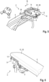
- Figure 5 shows a claimed embodiment of the seat device 2. Also in the embodiment according to Figure 5 the receiving unit 14 is joined to the support means 12 along a joining direction 18 running parallel to the longitudinal axis of the tilting vehicle. In a joined arrangement, a locking element 20 designed as a locking means 28 latches with a section of the support means 12.
- the handle unit 24 is fixed to the luggage bridge, i.e. on the receiving unit 14.
- the additional body 10 comprises a section 30 which continues the seat 4 and can be fixed to the receiving unit 14 by means of a coupling means 16 designed as a projection.
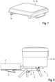
- Figure 7 shows an embodiment of the seat device 2, which corresponds to the embodiment according to Figure 6 Instead of defining a section 30 that continues the seat 4, the additional body 10 that can be arranged there comprises a transport container 32.
- a section 30 continuing the seat bench 4 or a transport container 32 can be arranged.
Landscapes
- Engineering & Computer Science (AREA)
- Mechanical Engineering (AREA)
- Seats For Vehicles (AREA)
Description
- Die Erfindung betrifft eine Sitzvorrichtung für ein Neigefahrzeug, mit mindestens einer Sitzbank, mit mindestens einer Rahmenstruktur, die ein Element eines Fahrzeugrahmens des Neigefahrzeugs umfasst oder am Fahrzeugrahmen festlegbar oder festgelegt ist und an der die Sitzbank festlegbar oder festgelegt ist, und mit mindestens einer Halteeinrichtung, die mindestens ein Tragmittel, das unmittelbar oder mittelbar an der Rahmenstruktur festgelegt ist, und die mindestens eine lösbar am Tragmittel anordenbare oder angeordnete Aufnahmeeinheit umfasst, an der ein Zusatzkörper anordenbar und mittels eines am Zusatzkörper festgelegten Koppelmittels an der Aufnahmeeinheit lösbar festlegbar ist.
- Sitzvorrichtungen für Neigefahrzeuge sind in unterschiedlichen Ausführungsformen und Varianten aus dem Stand der Technik bekannt. Zum einen sind Neigefahrzeuge mit Sitzvorrichtungen bekannt, bei denen die Sitzvorrichtung in Gänze eine Sitzbank umfasst, auf der sowohl ein Benutzer des Neigefahrzeugs als auch ein zusätzlicher Fahrgast, ein sogenannter Sozius, anordenbar sind.
- Darüber hinaus sind Sitzvorrichtungen für Neigefahrzeuge bekannt, bei denen an der Sitzbank eine Gepäckbrücke oder ein Halter fest und dauerhaft installierbar ist. Diese können die Sitzbank überfangen und reduzieren den Platz für einen zusätzlichen Mitfahrer. Um die Verkehrssicherheit zu gewährleisten, sind diese Gepäckbrücken durch Fachpersonal zu installieren, was sich als umständlich, zeitaufwendig und wenig flexibel erweist.
- Sitzvorrichtungen, die den Oberbegriff des Anspruchs 1 offenbaren, sind bekannt aus
DE 10 2006 046005 . - Eine Aufgabe eines Ausführungsbeispiels der Erfindung ist, eine Sitzvorrichtung für ein Neigefahrzeug vorzuschlagen, an der einfach und verkehrssicher ein Zusatzkörper anordenbar ist.
- Diese Aufgabe wird bei einer eingangs genannten Sitzvorrichtung für ein Neigefahrzeug gelöst durch mindestens ein Verriegelungselement, durch das die Aufnahmeeinheit in einer gefügten Anordnung lösbar an dem Tragmittel festlegbar ist, wobei das Verriegelungselement ein Rastmittel umfasst, durch das die Aufnahmeeinheit durch Bilden eines Hintergriffs bezüglich der Fügerichtung am Tragmittel festlegbar ist, mit mindestens einer Sitzbank, mit mindestens einer Rahmenstruktur, die ein Element eines Fahrzeugrahmens des Neigefahrzeugs umfasst oder am Fahrzeugrahmen festlegbar oder festgelegt ist und an der die Sitzbank festlegbar oder festgelegt ist, und mit mindestens einer Halteeinrichtung, die mindestens ein Tragmittel, das unmittelbar oder mittelbar an der Rahmenstruktur festgelegt ist, und die mindestens eine lösbar am Tragmittel anordenbare oder angeordnete Aufnahmeeinheit umfasst, an der ein Zusatzkörper anordenbar und mittels eines am Zusatzkörper festgelegten Koppelmittels an der Aufnahmeeinheit lösbar festlegbar ist.
- Dadurch, dass die Sitzvorrichtung ein Tragmittel umfasst, das unmittelbar oder mittelbar an der Rahmenstruktur festgelegt ist, ist ein Element der Halteeinrichtung verkehrssicher an der Sitzvorrichtung dauerhaft montierbar. Dadurch, dass die Aufnahmeeinheit an dem Tragmittel lösbar anordenbar ist und dass an der Aufnahmeeinheit ein Zusatzkörper anordenbar ist, kann die Aufnahmeeinheit und der Zusatzkörper bei Bedarf flexibel durch einen Benutzer des Neigefahrzeugs ohne zusätzliche fachmännische Unterstützung festgelegt werden.
- Die Aufnahmeeinheit kann grundsätzlich beliebig an der Tragstruktur festgelegt werden. Es sind Ausführungsformen der Sitzvorrichtung denkbar, bei denen die Aufnahmeeinheit auf einer der Sitzbank abgewandten Seite des Tragmittels anordenbar ist. Solchenfalls ist der Zusatzkörper unterhalb der Sitzbank angeordnet. Ferner sind Ausführungsformen der Sitzvorrichtung denkbar, bei denen die Aufnahmeeinheit an die Sitzbank angrenzend, insbesondere ein Ende der Sitzbank überragend, festlegbar ist. Solchenfalls ist der Zusatzkörper an die Sitzbank angrenzend und die Sitzbank entgegen der Fahrtrichtung fortsetzend angeordnet.
- Es werden Ausführungsformen der Sitzvorrichtung bevorzugt, bei denen die Aufnahmeeinheit in der gefügten Anordnung auf der der Sitzbank zugewandten Seite des Tragmittels anordenbar oder angeordnet ist und/oder bei denen die Aufnahmeeinheit die Sitzbank auf einer der Rahmenstruktur abgewandten Seite zumindest abschnittsweise oder in Gänze überfängt und/oder einen die Sitzbank fortsetzenden Abschnitt der Sitzbank umfasst.
- Wenn die Aufnahmeeinheit in der gefügten Anordnung auf der der Sitzbank zugewandten Seite des Tragmittels anordenbar ist, bietet sich eine flexible Gestaltung der Sitzbank. Solchenfalls kann der Zusatzkörper beispielsweise einen Abschnitt der Sitzbank umfassen, der an der Aufnahmeeinheit festlegbar ist. Solchenfalls ist die Sitzfläche der Sitzbank erweiterbar. Ferner kann der als zusätzliche Abschnitt der Sitzbank ausgebildete Zusatzkörper eine Rückenlehne oder Dergleichen umfassen.
- Wenn die Aufnahmeeinheit in der gefügten Anordnung auf der der Sitzbank zugewandten Seite des Tragmittels angeordnet ist und die Sitzbank auf einer der Rahmenstruktur abgewandten Seite zumindest abschnittsweise überfängt, lässt sich ein Teil der Sitzfläche der Sitzbank zumindest zeitweise zum Transportieren eines Zusatzkörpers verwenden, der beispielsweise eine Tasche, ein Helmfach, einen Transportbehälter (Topcase), eine Gepäckrolle oder Dergleichen umfassen kann. Die Aufnahmeeinheit kann solchenfalls eine Gepäckbrücke bilden.
- Darüber hinaus erweist es sich als vorteilhaft, wenn das Tragmittel ein Element der Rahmenstruktur umfasst oder unlösbar an der Rahmenstruktur festgelegt ist oder wenn das Tragmittel lösbar an der Rahmenstruktur festlegbar oder festgelegt ist.
- Wenn das Tragmittel ein Element der Rahmenstruktur umfasst, können Tragmittel und Rahmenstruktur ein gemeinsames Bauteil bilden, insbesondere das Tragmittels durch einen Abschnitt der Rahmenstruktur gebildet sein. Hierdurch lässt sich die Sitzvorrichtung bauteilreduziert ausbilden.
- Wenn das Tragmittel unlösbar an der Rahmenstruktur festgelegt ist, kann dieses beispielsweise durch Verkleben, Verschweißen oder Dergleichen erfolgen.
- Wenn das Tragmittel lösbar an der Rahmenstruktur festlegbar oder festgelegt ist, lässt sich die Sitzvorrichtung auf einfache Weise nachrüsten.
- Darüber hinaus können bei Ausführungsformen der Sitzvorrichtung Tragmittel und die Aufnahmeeinheit separat oder voneinander separierbare Bauteile umfassen.
- Wenn Tragmittel und Aufnahmeeinheit separate oder voneinander separierbare Bauteile umfassen, kann die Aufnahmeeinheit stets entfernt werden, wenn das Anordnen eines Zusatzkörpers nicht gewünscht oder nicht notwendig ist.
- Es erweist sich als vorteilhaft, wenn die Aufnahmeeinheit entlang einer parallel, quer oder schräg zur Längsachse des Neigefahrzeugs verlaufenden Fügerichtung am Tragmittel anordenbar ist. Die Aufnahmeeinheit kann entlang der Fügerichtung auf das Tragmittel aufschiebbar oder auf das Tragmittel aufsteckbar sein.
- Das Festlegen durch das Verriegelungselement kann formschlüssig, kraftschlüssig oder reibschlüssig erfolgen. Bei einer Weiterbildung letztgenannter Ausführungsform erweist es sich als vorteilhaft, wenn das Verriegelungselement ein Spannmittel umfasst, durch das die Aufnahmeeinheit mit einer Spannkraft beaufschlagbar und in Richtung auf das Tragmittel spann- oder klemmbar ist, insbesondere wenn das Spannmittel ein Federelement, einen Spannhebel und/oder eine Spann- oder Spreizplatte umfasst.
- Solchenfalls kann eine form-, kraft- oder reibschlüssige Verbindung zwischen Aufnahmeeinheit und Tragmittel weiter verbessert werden.
- Das Spannmittel kann beispielsweise einen Spannhebel umfassen, der durch manuelles Betätigen von einer geöffneten Position in eine geschlossene Position überführbar ist, wobei das Überführen des Spannhebels von der geöffneten Position in eine geschlossene Position eine vorherschende Klemmkraft erhöht. Darüber hinaus kann ein als Spannhebel ausgebildetes Spannmittel zusätzlich einen Hintergriff der Aufnahmeeinheit mit dem Tragmittel bilden, wenn die Aufnahmeeinheit beispielsweise einen zangenförmigen Abschnitt umfasst, der an einem korrespondierenden Abschnitt der Aufnahmeeinheit angelegt wird und durch Umlegen des Spannhebels der Hintergriff erzeugt wird.
- Wenn das Spannmittel beispielsweise ein Federelement umfasst, kann die Aufnahmeeinheit mit durch die Federelemente vorgespannte Rastnasen in korrespondierenden Aussparungen im Tragmittel verrasten.
- Wenn das Spannmittel eine Spann- oder Spreizplatte umfasst, kann ebenfalls eine Klemmkraft, die zwischen Aufnahmeeinheit und Tragmittel hergestellt wird, verstärkt werden.
- Um den Zusatzkörper auf einfache Weise an der Aufnahmeeinheit festzulegen, erweist es sich als vorteilhaft, wenn das Koppelmittel am Zusatzkörper einen Vorsprung umfasst, durch den der Zusatzkörper an der Aufnahmeeinheit und/oder am Tragmittel lösbar festlegbar oder festgelegt ist und/oder wenn das Koppelmittel ein automatisch oder manuell betätigbares Entriegelungsmittel umfasst durch das das Koppelmittel von der Aufnahmeeinheit und/oder dem Tragmittel lösbar ist.
- Durch das Vorsehen eines Koppelmittels am Zusatzkörper in Form eines Vorsprungs sowie durch das Vorsehen eines Entriegelungsmittels, kann der Zusatzkörper auf einfache Weise an der Aufnahmeeinheit festgelegt und wieder gelöst werden.
- Die Funktionalität der Sitzvorrichtung lässt sich verbessern, wenn die Sitzvorrichtung mindestens eine Griffeinheit für einen Benutzer des Neigefahrzeugs umfasst, die unmittelbar an der Rahmenstruktur festlegbar oder festgelegt ist und/oder die durch mindestens einen Abschnitt des Tragmittels und/oder der Aufnahmeeinheit gebildet ist.
- Wenn die Griffeinheit durch die Rahmenstruktur oder das Tragmittel gebildet ist, ist die Griffeinheit fahrzeugfest ausgebildet. Wenn die Rahmenstruktur die Griffeinheit ausbildet, können Rahmenstruktur und Griffeinheit ein gemeinsames einstückiges Bauteil umfassen. Solchenfalls ist die Sitzvorrichtung bauteilreduziert ausbildbar. Wenn das Tragmittel die Griffeinheit umfasst, kann durch das Anordnen des Tragmittels an der Rahmenstruktur auf einfache Weise eine Griffeinheit nachgerüstet werden. Hierdurch kann ein zusätzlicher Benutzer des Neigefahrzeugs, insbesondere ein Sozius, sich an dem Neigefahrzeug festhalten.
- Wenn die Griffeinheit an der Aufnahmeeinheit ausgebildet ist, ist die Griffeinheit gepäckbrückenfest ausgebildet.
- Bei einer Weiterbildung letztgenannter Ausführungsformen können Griffe der Griffeinheit relativ zum Neigefahrzeug ortsfest festgelegt sein oder von einer Vorratsstellung in eine Arbeitsstellung überführt werden, in der die Griffe der Griffeinheit durch einen Benutzer des Neigefahrzeugs greifbar sind. Solchenfalls können die Griff teleskopierbar oder schwenkbar ausgebildet sein.
- Weitere Merkmale, Einzelheiten und Vorteile der Erfindung ergeben sich aus den beigefügten Patentansprüchen, aus der zeichnerischen Darstellung und nachfolgenden Beschreibung bevorzugter Ausführungsformen der Sitzvorrichtung.
- In der Zeichnung zeigt:
- Figur 1
- Eine perspektivische Vorderansicht auf ein erstes nicht beanspruchten Ausführungsbeispiel der Sitzvorrichtung;
- Figur 2
- Eine Schnittansicht durch die Linie AA gemäß
Figur 1 ; - Figur 3
- Eine perspektivische Detailansicht auf einen Abschnitt einer Aufnahmeeinheit des nicht beanspruchten Ausführungsbeispiels der
Figuren 1 und 2 ; - Figur 4
- Eine perspektivische explosionsartige Darstellung auf ein zweites nicht beanspruchten Ausführungsbeispiel der Sitzvorrichtung;
- Figur 5
- Eine explosionsartige perspektivische Darstellung eines beanspruchtenAusführungsbeispiels der Sitzvorrichtung;
- Figur 6
- Eine perspektivische Vorderansicht auf ein Ausführungsbeispiel der Sitzvorrichtung;
- Figur 7
- Eine Detailansicht eines als Abschnitt einer Sitzbank ausgebildeten Zusatzkörpers gemäß
Figur 6 ; - Figur 8
- Eine Seitenansicht auf ein Ausführungsbeispiel der Sitzvorrichtung.
- Die Figuren zeigen Ausführungsbeispiele einer insgesamt mit dem Bezugszeichen 2 versehenen Sitzvorrichtung für ein Neigefahrzeug (in den Figuren nicht explizit dargestellt). Die Sitzvorrichtung 2 umfasst eine Sitzbank 4, auf der ein Benutzer des Neigefahrzeugs sitzend anordenbar ist. Darüber hinaus umfasst die Sitzvorrichtung 2 eine Rahmenstruktur 6, die ein Element eines Fahrzeugrahmens des Neigefahrzeugs umfasst. Die Sitzvorrichtung 2 umfasst eine Halteeinrichtung 8, an der Zusatzkörper 10 anordenbar sind. Hierzu umfasst die Halteeinrichtung 8 ein Tragmittel 12, das bei dem in den Figuren gezeigten Ausführungsbeispielen unmittelbar an der Rahmenstruktur 6 festgelegt ist. An dem Tragmittel 12 der Halteeinrichtung 8 ist lösbar eine Aufnahmeeinheit 14 anordenbar, an der der Zusatzkörper 10 anordenbar und mittels eines am Zusatzkörper 10 festgelegten Koppelmittels 16 in der Aufnahmeeinheit 14 lösbar festlegbar ist.
- Die Figuren zeigen Ausführungsbeispiele der Sitzvorrichtung 2, bei denen das Tragmittel 12 der Halteeinrichtung 8 jeweils unlösbar an der Rahmenstruktur 6 festgelegt ist.
- Bei den in den Figuren gezeigten Ausführungsbeispielen ist die Aufnahmeeinheit 14 jeweils auf einer der Sitzbank 4 zugewandten Seite des Tragmittels 12 angeordnet. Bei den Ausführungsbeispielen gemäß der
Figuren 1 ,4 und5 überfängt die Aufnahmeeinheit 14 die Sitzbank 4 auf der der Rahmenstruktur 6 abgewandten Seite der Sitzbank 4. Bei den Ausführungsbeispielen gemäß derFiguren 6 und7 liegt die Aufnahmeeinheit 14 unmittelbar auf der Rahmenstruktur 6 auf der der Sitzbank 4 zugewandten Seite an. - Die
Figuren 1 bis 3 zeigen ein nicht beanspruchtes Ausführungsbeispiel der Sitzvorrichtung 2, be der die Aufnahmeeinheit 14 entlang einer quer zur Längsachse des Neigefahrzeugs verlaufenden Fügerichtung 18 am Tragmittel 12 anordenbar ist. Hierzu weist die Aufnahmeeinheit 14 zangenartige Enden auf, die an einem korrespondierenden Abschnitt des Tragmittels 12 mittels Klemmung anordenbar sind. Zum Festlegen der Aufnahmeeinheit 14 umfasst das Ausführungsbeispiel gemäß derFiguren 1 bis 3 ein Verriegelungselement 20, das durch einen Spannhebel 22 gebildet ist. - Das Tragmittel 12 gemäß Ausführungsbeispiel der
Figuren 1 bis 3 umfasst zudem eine Griffeinheit 24, die durch einen Benutzer des Neigefahrzeugs manuell greifbar ist. Die Aufnahmeeinheit 14 wird solchenfalls an die Griffeinheit 24 geklammert. -
Figur 4 zeigt ein zweites nicht beanspruchten Ausführungsbeispiel der Sitzvorrichtung 2. Auch beim Ausführungsbeispiel gemäßFigur 2 bildet die Aufnahmeeinheit 14 eine Griffeinheit 24. Zum Fügen der Aufnahmeeinheit 14 an das Tragmittel 12 verläuft die Fügerichtung 18 bei dem Ausführungsbeispiel gemäßFigur 4 parallel zur Längsachse des Neigefahrzeugs. Um die Aufnahmeeinheit 14 in einer gefügten Anordnung mit dem Tragmittel 12 zu verbinden, umfasst das Verriegelungselement 20 des Ausführungsbeispiels gemäßFigur 4 eine Spreizplatte 26. -
Figur 5 zeigt ein beanspruchtes Ausführungsbeispiel der Sitzvorrichtung 2. Auch beim Ausführungsbeispiel gemäßFigur 5 wird die Aufnahmeeinheit 14 zum Fügen mit dem Tragmittel 12 entlang einer parallel zur Längsachse des Neigefahrzeugs verlaufenden Fügerichtung 18 gefügt. In einer gefügten Anordnung verrastet ein als Rastmittel 28 ausgebildetes Verriegelungselement 20 mit einem Abschnitt des Tragmittels 12. - Beim Ausführungsbeispiel gemäß
Figur 5 ist die Griffeinheit 24 gepäckbrückenfest also an der Aufnahmeeinheit 14 ausgebildet. - Die
Figuren 6 und7 zeigen ein Ausführungsbeispiel der Sitzvorrichtung 2. Bei diesem umfasst der Zusatzkörper 10 einen die Sitzbank 4 fortsetzenden Abschnitt 30, der mittels einen als Vorsprung ausgebildeten Koppelmittels 16 an der Aufnahmeeinheit 14 festlegbar ist. -
Figur 7 zeigt ein Ausführungsbeispiel der Sitzvorrichtung 2, der dem Ausführungsbeispiel gemäßFigur 6 ähnelt. Anstelle des Festlegens eines die Sitzbank 4 fortsetzenden Abschnitts 30 umfasst der dort anordenbare Zusatzkörper 10 einen Transportbehälter 32. - Durch die Ausbildung der Aufnahmeeinheit 14 als unmittelbar an der Rahmenstruktur 6 auf der der Sitzbank 4 zugewandten Seite der Rahmenstruktur 6 sind wahlweise ein die Sitzbank 4 fortsetzender Abschnitt 30 oder ein Transportbehälter 32 anordenbar.
-
- 2
- Sitzvorrichtung
- 4
- Sitzbank
- 6
- Rahmenstruktur
- 8
- Halteeinrichtung
- 10
- Zusatzkörper
- 12
- Tragmittel
- 14
- Aufnahmeeinheit
- 16
- Koppelmittel
- 18
- Fügerichtung
- 20
- Verriegelungselement
- 22
- Spannhebel
- 24
- Griffeinheit
- 26
- Spreizplatte
- 28
- Rastmittel
- 30
- Sitzbank fortsetzender Abschnitt
- 32
- Transportbehälter
Claims (8)
- Sitzvorrichtung (2) für ein Neigefahrzeug, mit mindestens einer Sitzbank (4), mit mindestens einer Rahmenstruktur (6), die ein Element eines Fahrzeugrahmens des Neigefahrzeugs umfasst oder am Fahrzeugrahmen festlegbar oder festgelegt ist und an der die Sitzbank (4) festlegbar oder festgelegt ist, und mit mindestens einer Halteeinrichtung (8), die mindestens ein Tragmittel (12), das unmittelbar oder mittelbar an der Rahmenstruktur (6) festgelegt ist, und die mindestens eine lösbar am Tragmittel (12) anordenbare oder angeordnete Aufnahmeeinheit (14) umfasst, an der ein Zusatzkörper (10) anordenbar und mittels eines am Zusatzkörper (10) festgelegten Koppelmittels (16) an der Aufnahmeeinheit (14) lösbar festlegbar ist, gekennzeichnet durch mindestens ein Verriegelungselement (20), durch das die Aufnahmeeinheit (14) in einer gefügten Anordnung lösbar an dem Tragmittel (12) festlegbar ist, wobei das Verriegelungselement (20) ein Rastmittel (28) umfasst, durch das die Aufnahmeeinheit (14) durch Bilden eines Hintergriffs bezüglich der Fügerichtung (18) am Tragmittel (12) festlegbar ist.
- Sitzvorrichtung (2) nach Anspruch 1, dadurch gekennzeichnet, dass die Aufnahmeeinheit (14) in der gefügten Anordnung auf der der Sitzbank (4) zugewandten Seite des Tragmittels (12) anordenbar oder angeordnet ist und/oder dass die Aufnahmeeinheit (14) die Sitzbank (4) auf einer der Rahmenstruktur (6) abgewandten Seite zumindest abschnittsweise oder in Gänze überfängt und/oder einen die Sitzbank (4) fortsetzenden Abschnitt (30) der Sitzbank (4) umfasst.
- Sitzvorrichtung (2) nach Anspruch 1 oder 2, dadurch gekennzeichnet, dass das Tragmittel (12) ein Element der Rahmenstruktur (6) umfasst oder unlösbar an der Rahmenstruktur (6) festgelegt ist oder dass das Tragmittel (12) lösbar an der Rahmenstruktur (6) festlegbar oder festgelegt ist.
- Sitzvorrichtung (2) nach mindestens einem der vorhergehenden Ansprüche, dadurch gekennzeichnet, dass das Tragmittel (12) und die Aufnahmeeinheit (14) separate oder voneinander separierbare Bauteile umfassen.
- Sitzvorrichtung (2) nach mindestens einem der vorhergehenden Ansprüche, dadurch gekennzeichnet, dass die Aufnahmeeinheit (14) entlang einer parallel, quer oder schräg zur Längsachse des Neigefahrzeugs verlaufenden Fügerichtung (18) am Tragmittel (12) anordenbar ist.
- Sitzvorrichtung (2) nach Anspruch 5, dadurch gekennzeichnet, dass das Verriegelungselement (20) ein Spannmittel umfasst, durch das die Aufnahmeeinheit (14) mit einer Spannkraft beaufschlagbar und in Richtung auf das Tragmittel (12) spann- oder klemmbar ist, insbesondere dass das Spannmittel ein Federelement, einen Spannhebel (22) und/oder eine Spann- oder Spreizplatte (26) umfasst.
- Sitzvorrichtung (2) nach mindestens einem der vorhergehenden Ansprüche, dadurch gekennzeichnet, dass das Koppelmittel (16) am Zusatzkörper (10) einen Vorsprung umfasst, durch den der Zusatzkörper (10) an der Aufnahmeeinheit (14) und/oder am Tragmittel (12) lösbar festlegbar oder festgelegt ist und/oder dass das Koppelmittel (16) ein automatisch oder manuell betätigbares Entriegelungsmittel umfasst durch das das Koppelmittel (16) von der Aufnahmeeinheit (14) und/oder dem Tragmittel (12) lösbar ist.
- Sitzvorrichtung (2) nach mindestens einem der vorhergehenden Ansprüche, gekennzeichnet durch mindestens eine Griffeinheit (24) für einen Benutzer des Neigefahrzeugs, die unmittelbar an der Rahmenstruktur (6) festlegbar oder festgelegt ist und/oder die durch mindestens einen Abschnitt des Tragmittels (12) und/oder der Aufnahmeeinheit (14) gebildet ist.
Applications Claiming Priority (2)
| Application Number | Priority Date | Filing Date | Title |
|---|---|---|---|
| DE102020121719.6A DE102020121719A1 (de) | 2020-08-19 | 2020-08-19 | Sitzvorrichtung für ein Neigefahrzeug |
| PCT/EP2021/068730 WO2022037841A1 (de) | 2020-08-19 | 2021-07-07 | Sitzvorrichtung für ein neigefahrzeug |
Publications (2)
| Publication Number | Publication Date |
|---|---|
| EP4200196A1 EP4200196A1 (de) | 2023-06-28 |
| EP4200196B1 true EP4200196B1 (de) | 2025-02-19 |
Family
ID=76971842
Family Applications (1)
| Application Number | Title | Priority Date | Filing Date |
|---|---|---|---|
| EP21743087.5A Active EP4200196B1 (de) | 2020-08-19 | 2021-07-07 | Sitzvorrichtung für ein neigefahrzeug |
Country Status (4)
| Country | Link |
|---|---|
| US (1) | US12337918B2 (de) |
| EP (1) | EP4200196B1 (de) |
| DE (1) | DE102020121719A1 (de) |
| WO (1) | WO2022037841A1 (de) |
Families Citing this family (1)
| Publication number | Priority date | Publication date | Assignee | Title |
|---|---|---|---|---|
| DE102024102561A1 (de) * | 2024-01-30 | 2025-07-31 | Bayerische Motoren Werke Aktiengesellschaft | Sitzbank für ein Kraftrad sowie Kraftrad |
Family Cites Families (16)
| Publication number | Priority date | Publication date | Assignee | Title |
|---|---|---|---|---|
| JPS58190283U (ja) | 1982-06-12 | 1983-12-17 | 亀川 誠 | バイク用後部物入れ取付装置 |
| JPS5964381U (ja) | 1982-10-22 | 1984-04-27 | 本田技研工業株式会社 | リヤトランク付き自動二輪車 |
| US5558260A (en) * | 1995-04-18 | 1996-09-24 | Reichert; Cory A. | Detachable motorcycle passenger seat and/or luggage rack |
| US5713629A (en) * | 1996-12-26 | 1998-02-03 | Plackis; Thomas | Convertible motorcycle seats |
| JPH11263261A (ja) | 1998-03-18 | 1999-09-28 | Honda Motor Co Ltd | 自動二輪車の荷台装置 |
| US7111903B1 (en) * | 2003-08-14 | 2006-09-26 | Bill Snelson | Supplemental motorcycle seat |
| JP2007091140A (ja) | 2005-09-30 | 2007-04-12 | Honda Motor Co Ltd | 鞍乗り型車両の収納部構造 |
| KR100942247B1 (ko) * | 2009-11-12 | 2010-02-18 | 주식회사 레드블리츠 | 스쿠터용 슬라이더 짐받이 |
| US20110139843A1 (en) * | 2009-12-11 | 2011-06-16 | Thomas Barry H | Motorcycle seat-back adjustement device and method |
| JP5872447B2 (ja) | 2012-12-13 | 2016-03-01 | 本田技研工業株式会社 | 鞍乗り型車両の後部構造 |
| JP2014213733A (ja) | 2013-04-25 | 2014-11-17 | 本田技研工業株式会社 | 自動二輪車 |
| JP6266408B2 (ja) | 2014-03-31 | 2018-01-24 | 川崎重工業株式会社 | 自動二輪車のタンデムグリップ・ユニット |
| WO2016038530A1 (en) | 2014-09-09 | 2016-03-17 | Perri Nicola | Device for mounting a top box to a motorcycle |
| JP6016864B2 (ja) * | 2014-09-30 | 2016-10-26 | 本田技研工業株式会社 | 乗車部を備える車両 |
| JP6597115B2 (ja) * | 2015-09-24 | 2019-10-30 | テイ・エス テック株式会社 | 跨座式シート |
| WO2017203544A1 (en) | 2016-05-23 | 2017-11-30 | Giaramita David | Baggage transport container for vehicles, motorcycles and the like |
-
2020
- 2020-08-19 DE DE102020121719.6A patent/DE102020121719A1/de active Pending
-
2021
- 2021-07-07 EP EP21743087.5A patent/EP4200196B1/de active Active
- 2021-07-07 WO PCT/EP2021/068730 patent/WO2022037841A1/de not_active Ceased
- 2021-07-07 US US18/013,351 patent/US12337918B2/en active Active
Also Published As
| Publication number | Publication date |
|---|---|
| US20230294783A1 (en) | 2023-09-21 |
| EP4200196A1 (de) | 2023-06-28 |
| US12337918B2 (en) | 2025-06-24 |
| DE102020121719A1 (de) | 2022-02-24 |
| WO2022037841A1 (de) | 2022-02-24 |
Similar Documents
| Publication | Publication Date | Title |
|---|---|---|
| DE112010002531T5 (de) | Querstangen-klemmvorrichtung | |
| DE102008030594A1 (de) | Gepäckständer und Beifahrersitz für ein Motorrad | |
| EP2014509B1 (de) | Abdeckung für einen Spalt | |
| DE20013483U1 (de) | Anhängbarer Kindersitz | |
| DE102006059077A1 (de) | Wischblatt | |
| DE19929005C1 (de) | Riegelvorrichtung zur Frachtfallsicherung | |
| DE19928862A1 (de) | Befestigungsvorrichtung für einen Kindersitz | |
| DE1505481B2 (de) | Fahrzeugsitz | |
| DE602005004635T2 (de) | Fahrzeugkindersitz | |
| DE29800290U1 (de) | Verstelleinrichtung für eine Fahrzeugsitz-Rückenlehne | |
| DE3329725C2 (de) | ||
| DE19812490C2 (de) | Einrichtung zur lösbaren Befestigung eines Sitzes, insbesondere Fahrzeugsitzes, an einer längsverlaufenden Schiene | |
| WO2022037841A1 (de) | Sitzvorrichtung für ein neigefahrzeug | |
| WO2014131529A1 (de) | Lehnenrahmen für einen sitz, insbesondere einen fahrzeugsitz und fahrzeugsitz | |
| WO2018018060A1 (de) | Kindersitz | |
| DE10206780A1 (de) | Befestigungsvorrichtung für einen Kindersitz | |
| EP2842806B1 (de) | Gepäckraumbodeneinrichtung für einen Gepäckraum eines Personenkraftwagens | |
| DE102015006564A1 (de) | Drehmomentschrauber-System | |
| EP0970843B1 (de) | Sitzkonstruktion mit Umklappfunktion für Kfz-Sitze | |
| DE202020005398U1 (de) | Passagiersitze | |
| EP2607176B1 (de) | Lastenträger mit einem Lasttragteil und einem Stützelement | |
| DE102012012358A1 (de) | Sitzadapter, Kraftfahrzeugsitz, Sitzeinrichtung,Kraftfahrzeug und Verfahren hierzu | |
| DE102020129388B3 (de) | Sicherungsvorrichtung zum Sichern von Ladegut | |
| DE102011120294B4 (de) | Lenksäule für ein Kraftfahrzeug, insbesondere für einen Personenkraftwagen | |
| WO2019068603A1 (de) | Flugzeugsitzvorrichtung |
Legal Events
| Date | Code | Title | Description |
|---|---|---|---|
| STAA | Information on the status of an ep patent application or granted ep patent |
Free format text: STATUS: UNKNOWN |
|
| STAA | Information on the status of an ep patent application or granted ep patent |
Free format text: STATUS: THE INTERNATIONAL PUBLICATION HAS BEEN MADE |
|
| PUAI | Public reference made under article 153(3) epc to a published international application that has entered the european phase |
Free format text: ORIGINAL CODE: 0009012 |
|
| STAA | Information on the status of an ep patent application or granted ep patent |
Free format text: STATUS: REQUEST FOR EXAMINATION WAS MADE |
|
| 17P | Request for examination filed |
Effective date: 20230210 |
|
| AK | Designated contracting states |
Kind code of ref document: A1 Designated state(s): AL AT BE BG CH CY CZ DE DK EE ES FI FR GB GR HR HU IE IS IT LI LT LU LV MC MK MT NL NO PL PT RO RS SE SI SK SM TR |
|
| DAV | Request for validation of the european patent (deleted) | ||
| DAX | Request for extension of the european patent (deleted) | ||
| GRAP | Despatch of communication of intention to grant a patent |
Free format text: ORIGINAL CODE: EPIDOSNIGR1 |
|
| STAA | Information on the status of an ep patent application or granted ep patent |
Free format text: STATUS: GRANT OF PATENT IS INTENDED |
|
| INTG | Intention to grant announced |
Effective date: 20240906 |
|
| GRAJ | Information related to disapproval of communication of intention to grant by the applicant or resumption of examination proceedings by the epo deleted |
Free format text: ORIGINAL CODE: EPIDOSDIGR1 |
|
| GRAP | Despatch of communication of intention to grant a patent |
Free format text: ORIGINAL CODE: EPIDOSNIGR1 |
|
| INTG | Intention to grant announced |
Effective date: 20241029 |
|
| GRAS | Grant fee paid |
Free format text: ORIGINAL CODE: EPIDOSNIGR3 |
|
| GRAA | (expected) grant |
Free format text: ORIGINAL CODE: 0009210 |
|
| STAA | Information on the status of an ep patent application or granted ep patent |
Free format text: STATUS: THE PATENT HAS BEEN GRANTED |
|
| AK | Designated contracting states |
Kind code of ref document: B1 Designated state(s): AL AT BE BG CH CY CZ DE DK EE ES FI FR GB GR HR HU IE IS IT LI LT LU LV MC MK MT NL NO PL PT RO RS SE SI SK SM TR |
|
| REG | Reference to a national code |
Ref country code: GB Ref legal event code: FG4D Free format text: NOT ENGLISH |
|
| REG | Reference to a national code |
Ref country code: CH Ref legal event code: EP |
|
| REG | Reference to a national code |
Ref country code: DE Ref legal event code: R096 Ref document number: 502021006709 Country of ref document: DE |
|
| REG | Reference to a national code |
Ref country code: IE Ref legal event code: FG4D Free format text: LANGUAGE OF EP DOCUMENT: GERMAN |
|
| REG | Reference to a national code |
Ref country code: NL Ref legal event code: MP Effective date: 20250219 |
|
| PG25 | Lapsed in a contracting state [announced via postgrant information from national office to epo] |
Ref country code: RS Free format text: LAPSE BECAUSE OF FAILURE TO SUBMIT A TRANSLATION OF THE DESCRIPTION OR TO PAY THE FEE WITHIN THE PRESCRIBED TIME-LIMIT Effective date: 20250519 |
|
| PG25 | Lapsed in a contracting state [announced via postgrant information from national office to epo] |
Ref country code: FI Free format text: LAPSE BECAUSE OF FAILURE TO SUBMIT A TRANSLATION OF THE DESCRIPTION OR TO PAY THE FEE WITHIN THE PRESCRIBED TIME-LIMIT Effective date: 20250219 |
|
| PG25 | Lapsed in a contracting state [announced via postgrant information from national office to epo] |
Ref country code: PL Free format text: LAPSE BECAUSE OF FAILURE TO SUBMIT A TRANSLATION OF THE DESCRIPTION OR TO PAY THE FEE WITHIN THE PRESCRIBED TIME-LIMIT Effective date: 20250219 |
|
| PG25 | Lapsed in a contracting state [announced via postgrant information from national office to epo] |
Ref country code: ES Free format text: LAPSE BECAUSE OF FAILURE TO SUBMIT A TRANSLATION OF THE DESCRIPTION OR TO PAY THE FEE WITHIN THE PRESCRIBED TIME-LIMIT Effective date: 20250219 |
|
| REG | Reference to a national code |
Ref country code: LT Ref legal event code: MG9D |
|
| PG25 | Lapsed in a contracting state [announced via postgrant information from national office to epo] |
Ref country code: NO Free format text: LAPSE BECAUSE OF FAILURE TO SUBMIT A TRANSLATION OF THE DESCRIPTION OR TO PAY THE FEE WITHIN THE PRESCRIBED TIME-LIMIT Effective date: 20250519 Ref country code: IS Free format text: LAPSE BECAUSE OF FAILURE TO SUBMIT A TRANSLATION OF THE DESCRIPTION OR TO PAY THE FEE WITHIN THE PRESCRIBED TIME-LIMIT Effective date: 20250619 |
|
| PG25 | Lapsed in a contracting state [announced via postgrant information from national office to epo] |
Ref country code: NL Free format text: LAPSE BECAUSE OF FAILURE TO SUBMIT A TRANSLATION OF THE DESCRIPTION OR TO PAY THE FEE WITHIN THE PRESCRIBED TIME-LIMIT Effective date: 20250219 |
|
| PG25 | Lapsed in a contracting state [announced via postgrant information from national office to epo] |
Ref country code: HR Free format text: LAPSE BECAUSE OF FAILURE TO SUBMIT A TRANSLATION OF THE DESCRIPTION OR TO PAY THE FEE WITHIN THE PRESCRIBED TIME-LIMIT Effective date: 20250219 |
|
| PG25 | Lapsed in a contracting state [announced via postgrant information from national office to epo] |
Ref country code: LV Free format text: LAPSE BECAUSE OF FAILURE TO SUBMIT A TRANSLATION OF THE DESCRIPTION OR TO PAY THE FEE WITHIN THE PRESCRIBED TIME-LIMIT Effective date: 20250219 Ref country code: PT Free format text: LAPSE BECAUSE OF FAILURE TO SUBMIT A TRANSLATION OF THE DESCRIPTION OR TO PAY THE FEE WITHIN THE PRESCRIBED TIME-LIMIT Effective date: 20250620 |
|
| PG25 | Lapsed in a contracting state [announced via postgrant information from national office to epo] |
Ref country code: BG Free format text: LAPSE BECAUSE OF FAILURE TO SUBMIT A TRANSLATION OF THE DESCRIPTION OR TO PAY THE FEE WITHIN THE PRESCRIBED TIME-LIMIT Effective date: 20250219 Ref country code: GR Free format text: LAPSE BECAUSE OF FAILURE TO SUBMIT A TRANSLATION OF THE DESCRIPTION OR TO PAY THE FEE WITHIN THE PRESCRIBED TIME-LIMIT Effective date: 20250520 |
|
| PG25 | Lapsed in a contracting state [announced via postgrant information from national office to epo] |
Ref country code: SE Free format text: LAPSE BECAUSE OF FAILURE TO SUBMIT A TRANSLATION OF THE DESCRIPTION OR TO PAY THE FEE WITHIN THE PRESCRIBED TIME-LIMIT Effective date: 20250219 |
|
| PG25 | Lapsed in a contracting state [announced via postgrant information from national office to epo] |
Ref country code: SM Free format text: LAPSE BECAUSE OF FAILURE TO SUBMIT A TRANSLATION OF THE DESCRIPTION OR TO PAY THE FEE WITHIN THE PRESCRIBED TIME-LIMIT Effective date: 20250219 |
|
| PG25 | Lapsed in a contracting state [announced via postgrant information from national office to epo] |
Ref country code: DK Free format text: LAPSE BECAUSE OF FAILURE TO SUBMIT A TRANSLATION OF THE DESCRIPTION OR TO PAY THE FEE WITHIN THE PRESCRIBED TIME-LIMIT Effective date: 20250219 |
|
| PGFP | Annual fee paid to national office [announced via postgrant information from national office to epo] |
Ref country code: DE Payment date: 20250702 Year of fee payment: 5 |
|
| PGFP | Annual fee paid to national office [announced via postgrant information from national office to epo] |
Ref country code: IT Payment date: 20250731 Year of fee payment: 5 |
|
| PGFP | Annual fee paid to national office [announced via postgrant information from national office to epo] |
Ref country code: GB Payment date: 20250724 Year of fee payment: 5 |
|
| PGFP | Annual fee paid to national office [announced via postgrant information from national office to epo] |
Ref country code: FR Payment date: 20250723 Year of fee payment: 5 Ref country code: AT Payment date: 20251020 Year of fee payment: 5 |
|
| PG25 | Lapsed in a contracting state [announced via postgrant information from national office to epo] |
Ref country code: CZ Free format text: LAPSE BECAUSE OF FAILURE TO SUBMIT A TRANSLATION OF THE DESCRIPTION OR TO PAY THE FEE WITHIN THE PRESCRIBED TIME-LIMIT Effective date: 20250219 Ref country code: EE Free format text: LAPSE BECAUSE OF FAILURE TO SUBMIT A TRANSLATION OF THE DESCRIPTION OR TO PAY THE FEE WITHIN THE PRESCRIBED TIME-LIMIT Effective date: 20250219 |
|
| PG25 | Lapsed in a contracting state [announced via postgrant information from national office to epo] |
Ref country code: RO Free format text: LAPSE BECAUSE OF FAILURE TO SUBMIT A TRANSLATION OF THE DESCRIPTION OR TO PAY THE FEE WITHIN THE PRESCRIBED TIME-LIMIT Effective date: 20250219 |
|
| PG25 | Lapsed in a contracting state [announced via postgrant information from national office to epo] |
Ref country code: SK Free format text: LAPSE BECAUSE OF FAILURE TO SUBMIT A TRANSLATION OF THE DESCRIPTION OR TO PAY THE FEE WITHIN THE PRESCRIBED TIME-LIMIT Effective date: 20250219 |
|
| REG | Reference to a national code |
Ref country code: DE Ref legal event code: R097 Ref document number: 502021006709 Country of ref document: DE |
|
| PLBE | No opposition filed within time limit |
Free format text: ORIGINAL CODE: 0009261 |
|
| STAA | Information on the status of an ep patent application or granted ep patent |
Free format text: STATUS: NO OPPOSITION FILED WITHIN TIME LIMIT |
|
| REG | Reference to a national code |
Ref country code: CH Ref legal event code: L10 Free format text: ST27 STATUS EVENT CODE: U-0-0-L10-L00 (AS PROVIDED BY THE NATIONAL OFFICE) Effective date: 20251231 |
|
| 26N | No opposition filed |
Effective date: 20251120 |
|
| REG | Reference to a national code |
Ref country code: CH Ref legal event code: H13 Free format text: ST27 STATUS EVENT CODE: U-0-0-H10-H13 (AS PROVIDED BY THE NATIONAL OFFICE) Effective date: 20260224 |
|
| PG25 | Lapsed in a contracting state [announced via postgrant information from national office to epo] |
Ref country code: LU Free format text: LAPSE BECAUSE OF NON-PAYMENT OF DUE FEES Effective date: 20250707 |
|
| REG | Reference to a national code |
Ref country code: BE Ref legal event code: MM Effective date: 20250731 |
|
| PG25 | Lapsed in a contracting state [announced via postgrant information from national office to epo] |
Ref country code: BE Free format text: LAPSE BECAUSE OF NON-PAYMENT OF DUE FEES Effective date: 20250731 |
|
| PG25 | Lapsed in a contracting state [announced via postgrant information from national office to epo] |
Ref country code: CH Free format text: LAPSE BECAUSE OF NON-PAYMENT OF DUE FEES Effective date: 20250731 |