EP4197894A1 - Corps flottant - Google Patents
Corps flottant Download PDFInfo
- Publication number
- EP4197894A1 EP4197894A1 EP21886351.2A EP21886351A EP4197894A1 EP 4197894 A1 EP4197894 A1 EP 4197894A1 EP 21886351 A EP21886351 A EP 21886351A EP 4197894 A1 EP4197894 A1 EP 4197894A1
- Authority
- EP
- European Patent Office
- Prior art keywords
- tank
- pipe
- carbon dioxide
- loading
- liquefied carbon
- Prior art date
- Legal status (The legal status is an assumption and is not a legal conclusion. Google has not performed a legal analysis and makes no representation as to the accuracy of the status listed.)
- Pending
Links
- CURLTUGMZLYLDI-UHFFFAOYSA-N Carbon dioxide Chemical compound O=C=O CURLTUGMZLYLDI-UHFFFAOYSA-N 0.000 claims abstract description 142
- 229910002092 carbon dioxide Inorganic materials 0.000 claims abstract description 66
- 239000001569 carbon dioxide Substances 0.000 claims abstract description 66
- 235000011089 carbon dioxide Nutrition 0.000 description 10
- 239000007789 gas Substances 0.000 description 8
- 238000012423 maintenance Methods 0.000 description 8
- 230000015572 biosynthetic process Effects 0.000 description 7
- 230000008020 evaporation Effects 0.000 description 4
- 238000001704 evaporation Methods 0.000 description 4
- 239000003949 liquefied natural gas Substances 0.000 description 4
- 239000007788 liquid Substances 0.000 description 4
- 238000013461 design Methods 0.000 description 3
- 239000002828 fuel tank Substances 0.000 description 3
- 238000013459 approach Methods 0.000 description 2
- 230000000694 effects Effects 0.000 description 2
- 238000007747 plating Methods 0.000 description 2
- 230000008023 solidification Effects 0.000 description 2
- 238000007711 solidification Methods 0.000 description 2
- 230000001133 acceleration Effects 0.000 description 1
- 230000004308 accommodation Effects 0.000 description 1
- QVGXLLKOCUKJST-UHFFFAOYSA-N atomic oxygen Chemical compound [O] QVGXLLKOCUKJST-UHFFFAOYSA-N 0.000 description 1
- 238000001514 detection method Methods 0.000 description 1
- 239000007791 liquid phase Substances 0.000 description 1
- 238000012986 modification Methods 0.000 description 1
- 230000004048 modification Effects 0.000 description 1
- 229910052760 oxygen Inorganic materials 0.000 description 1
- 239000001301 oxygen Substances 0.000 description 1
- 230000000149 penetrating effect Effects 0.000 description 1
- 239000012071 phase Substances 0.000 description 1
- 239000007790 solid phase Substances 0.000 description 1
- 238000013519 translation Methods 0.000 description 1
Images

Classifications
-
- B—PERFORMING OPERATIONS; TRANSPORTING
- B63—SHIPS OR OTHER WATERBORNE VESSELS; RELATED EQUIPMENT
- B63B—SHIPS OR OTHER WATERBORNE VESSELS; EQUIPMENT FOR SHIPPING
- B63B25/00—Load-accommodating arrangements, e.g. stowing, trimming; Vessels characterised thereby
- B63B25/02—Load-accommodating arrangements, e.g. stowing, trimming; Vessels characterised thereby for bulk goods
- B63B25/08—Load-accommodating arrangements, e.g. stowing, trimming; Vessels characterised thereby for bulk goods fluid
- B63B25/12—Load-accommodating arrangements, e.g. stowing, trimming; Vessels characterised thereby for bulk goods fluid closed
- B63B25/14—Load-accommodating arrangements, e.g. stowing, trimming; Vessels characterised thereby for bulk goods fluid closed pressurised
-
- B—PERFORMING OPERATIONS; TRANSPORTING
- B63—SHIPS OR OTHER WATERBORNE VESSELS; RELATED EQUIPMENT
- B63B—SHIPS OR OTHER WATERBORNE VESSELS; EQUIPMENT FOR SHIPPING
- B63B27/00—Arrangement of ship-based loading or unloading equipment for cargo or passengers
- B63B27/24—Arrangement of ship-based loading or unloading equipment for cargo or passengers of pipe-lines
-
- F—MECHANICAL ENGINEERING; LIGHTING; HEATING; WEAPONS; BLASTING
- F17—STORING OR DISTRIBUTING GASES OR LIQUIDS
- F17C—VESSELS FOR CONTAINING OR STORING COMPRESSED, LIQUEFIED OR SOLIDIFIED GASES; FIXED-CAPACITY GAS-HOLDERS; FILLING VESSELS WITH, OR DISCHARGING FROM VESSELS, COMPRESSED, LIQUEFIED, OR SOLIDIFIED GASES
- F17C3/00—Vessels not under pressure
- F17C3/02—Vessels not under pressure with provision for thermal insulation
-
- F—MECHANICAL ENGINEERING; LIGHTING; HEATING; WEAPONS; BLASTING
- F17—STORING OR DISTRIBUTING GASES OR LIQUIDS
- F17C—VESSELS FOR CONTAINING OR STORING COMPRESSED, LIQUEFIED OR SOLIDIFIED GASES; FIXED-CAPACITY GAS-HOLDERS; FILLING VESSELS WITH, OR DISCHARGING FROM VESSELS, COMPRESSED, LIQUEFIED, OR SOLIDIFIED GASES
- F17C6/00—Methods and apparatus for filling vessels not under pressure with liquefied or solidified gases
-
- F—MECHANICAL ENGINEERING; LIGHTING; HEATING; WEAPONS; BLASTING
- F17—STORING OR DISTRIBUTING GASES OR LIQUIDS
- F17C—VESSELS FOR CONTAINING OR STORING COMPRESSED, LIQUEFIED OR SOLIDIFIED GASES; FIXED-CAPACITY GAS-HOLDERS; FILLING VESSELS WITH, OR DISCHARGING FROM VESSELS, COMPRESSED, LIQUEFIED, OR SOLIDIFIED GASES
- F17C9/00—Methods or apparatus for discharging liquefied or solidified gases from vessels not under pressure
-
- B—PERFORMING OPERATIONS; TRANSPORTING
- B63—SHIPS OR OTHER WATERBORNE VESSELS; RELATED EQUIPMENT
- B63B—SHIPS OR OTHER WATERBORNE VESSELS; EQUIPMENT FOR SHIPPING
- B63B25/00—Load-accommodating arrangements, e.g. stowing, trimming; Vessels characterised thereby
- B63B25/02—Load-accommodating arrangements, e.g. stowing, trimming; Vessels characterised thereby for bulk goods
- B63B25/08—Load-accommodating arrangements, e.g. stowing, trimming; Vessels characterised thereby for bulk goods fluid
- B63B2025/087—Load-accommodating arrangements, e.g. stowing, trimming; Vessels characterised thereby for bulk goods fluid comprising self-contained tanks installed in the ship structure as separate units
-
- F—MECHANICAL ENGINEERING; LIGHTING; HEATING; WEAPONS; BLASTING
- F17—STORING OR DISTRIBUTING GASES OR LIQUIDS
- F17C—VESSELS FOR CONTAINING OR STORING COMPRESSED, LIQUEFIED OR SOLIDIFIED GASES; FIXED-CAPACITY GAS-HOLDERS; FILLING VESSELS WITH, OR DISCHARGING FROM VESSELS, COMPRESSED, LIQUEFIED, OR SOLIDIFIED GASES
- F17C2201/00—Vessel construction, in particular geometry, arrangement or size
- F17C2201/01—Shape
- F17C2201/0104—Shape cylindrical
-
- F—MECHANICAL ENGINEERING; LIGHTING; HEATING; WEAPONS; BLASTING
- F17—STORING OR DISTRIBUTING GASES OR LIQUIDS
- F17C—VESSELS FOR CONTAINING OR STORING COMPRESSED, LIQUEFIED OR SOLIDIFIED GASES; FIXED-CAPACITY GAS-HOLDERS; FILLING VESSELS WITH, OR DISCHARGING FROM VESSELS, COMPRESSED, LIQUEFIED, OR SOLIDIFIED GASES
- F17C2201/00—Vessel construction, in particular geometry, arrangement or size
- F17C2201/03—Orientation
- F17C2201/035—Orientation with substantially horizontal main axis
-
- F—MECHANICAL ENGINEERING; LIGHTING; HEATING; WEAPONS; BLASTING
- F17—STORING OR DISTRIBUTING GASES OR LIQUIDS
- F17C—VESSELS FOR CONTAINING OR STORING COMPRESSED, LIQUEFIED OR SOLIDIFIED GASES; FIXED-CAPACITY GAS-HOLDERS; FILLING VESSELS WITH, OR DISCHARGING FROM VESSELS, COMPRESSED, LIQUEFIED, OR SOLIDIFIED GASES
- F17C2201/00—Vessel construction, in particular geometry, arrangement or size
- F17C2201/05—Size
- F17C2201/052—Size large (>1000 m3)
-
- F—MECHANICAL ENGINEERING; LIGHTING; HEATING; WEAPONS; BLASTING
- F17—STORING OR DISTRIBUTING GASES OR LIQUIDS
- F17C—VESSELS FOR CONTAINING OR STORING COMPRESSED, LIQUEFIED OR SOLIDIFIED GASES; FIXED-CAPACITY GAS-HOLDERS; FILLING VESSELS WITH, OR DISCHARGING FROM VESSELS, COMPRESSED, LIQUEFIED, OR SOLIDIFIED GASES
- F17C2201/00—Vessel construction, in particular geometry, arrangement or size
- F17C2201/05—Size
- F17C2201/054—Size medium (>1 m3)
-
- F—MECHANICAL ENGINEERING; LIGHTING; HEATING; WEAPONS; BLASTING
- F17—STORING OR DISTRIBUTING GASES OR LIQUIDS
- F17C—VESSELS FOR CONTAINING OR STORING COMPRESSED, LIQUEFIED OR SOLIDIFIED GASES; FIXED-CAPACITY GAS-HOLDERS; FILLING VESSELS WITH, OR DISCHARGING FROM VESSELS, COMPRESSED, LIQUEFIED, OR SOLIDIFIED GASES
- F17C2205/00—Vessel construction, in particular mounting arrangements, attachments or identifications means
- F17C2205/01—Mounting arrangements
- F17C2205/0123—Mounting arrangements characterised by number of vessels
- F17C2205/013—Two or more vessels
-
- F—MECHANICAL ENGINEERING; LIGHTING; HEATING; WEAPONS; BLASTING
- F17—STORING OR DISTRIBUTING GASES OR LIQUIDS
- F17C—VESSELS FOR CONTAINING OR STORING COMPRESSED, LIQUEFIED OR SOLIDIFIED GASES; FIXED-CAPACITY GAS-HOLDERS; FILLING VESSELS WITH, OR DISCHARGING FROM VESSELS, COMPRESSED, LIQUEFIED, OR SOLIDIFIED GASES
- F17C2205/00—Vessel construction, in particular mounting arrangements, attachments or identifications means
- F17C2205/03—Fluid connections, filters, valves, closure means or other attachments
- F17C2205/0302—Fittings, valves, filters, or components in connection with the gas storage device
- F17C2205/0323—Valves
- F17C2205/0326—Valves electrically actuated
-
- F—MECHANICAL ENGINEERING; LIGHTING; HEATING; WEAPONS; BLASTING
- F17—STORING OR DISTRIBUTING GASES OR LIQUIDS
- F17C—VESSELS FOR CONTAINING OR STORING COMPRESSED, LIQUEFIED OR SOLIDIFIED GASES; FIXED-CAPACITY GAS-HOLDERS; FILLING VESSELS WITH, OR DISCHARGING FROM VESSELS, COMPRESSED, LIQUEFIED, OR SOLIDIFIED GASES
- F17C2205/00—Vessel construction, in particular mounting arrangements, attachments or identifications means
- F17C2205/03—Fluid connections, filters, valves, closure means or other attachments
- F17C2205/0302—Fittings, valves, filters, or components in connection with the gas storage device
- F17C2205/0352—Pipes
-
- F—MECHANICAL ENGINEERING; LIGHTING; HEATING; WEAPONS; BLASTING
- F17—STORING OR DISTRIBUTING GASES OR LIQUIDS
- F17C—VESSELS FOR CONTAINING OR STORING COMPRESSED, LIQUEFIED OR SOLIDIFIED GASES; FIXED-CAPACITY GAS-HOLDERS; FILLING VESSELS WITH, OR DISCHARGING FROM VESSELS, COMPRESSED, LIQUEFIED, OR SOLIDIFIED GASES
- F17C2221/00—Handled fluid, in particular type of fluid
- F17C2221/01—Pure fluids
- F17C2221/013—Carbone dioxide
-
- F—MECHANICAL ENGINEERING; LIGHTING; HEATING; WEAPONS; BLASTING
- F17—STORING OR DISTRIBUTING GASES OR LIQUIDS
- F17C—VESSELS FOR CONTAINING OR STORING COMPRESSED, LIQUEFIED OR SOLIDIFIED GASES; FIXED-CAPACITY GAS-HOLDERS; FILLING VESSELS WITH, OR DISCHARGING FROM VESSELS, COMPRESSED, LIQUEFIED, OR SOLIDIFIED GASES
- F17C2223/00—Handled fluid before transfer, i.e. state of fluid when stored in the vessel or before transfer from the vessel
- F17C2223/01—Handled fluid before transfer, i.e. state of fluid when stored in the vessel or before transfer from the vessel characterised by the phase
- F17C2223/0146—Two-phase
- F17C2223/0153—Liquefied gas, e.g. LPG, GPL
-
- F—MECHANICAL ENGINEERING; LIGHTING; HEATING; WEAPONS; BLASTING
- F17—STORING OR DISTRIBUTING GASES OR LIQUIDS
- F17C—VESSELS FOR CONTAINING OR STORING COMPRESSED, LIQUEFIED OR SOLIDIFIED GASES; FIXED-CAPACITY GAS-HOLDERS; FILLING VESSELS WITH, OR DISCHARGING FROM VESSELS, COMPRESSED, LIQUEFIED, OR SOLIDIFIED GASES
- F17C2223/00—Handled fluid before transfer, i.e. state of fluid when stored in the vessel or before transfer from the vessel
- F17C2223/01—Handled fluid before transfer, i.e. state of fluid when stored in the vessel or before transfer from the vessel characterised by the phase
- F17C2223/0192—Three-phase, e.g. CO2 at triple point
-
- F—MECHANICAL ENGINEERING; LIGHTING; HEATING; WEAPONS; BLASTING
- F17—STORING OR DISTRIBUTING GASES OR LIQUIDS
- F17C—VESSELS FOR CONTAINING OR STORING COMPRESSED, LIQUEFIED OR SOLIDIFIED GASES; FIXED-CAPACITY GAS-HOLDERS; FILLING VESSELS WITH, OR DISCHARGING FROM VESSELS, COMPRESSED, LIQUEFIED, OR SOLIDIFIED GASES
- F17C2223/00—Handled fluid before transfer, i.e. state of fluid when stored in the vessel or before transfer from the vessel
- F17C2223/03—Handled fluid before transfer, i.e. state of fluid when stored in the vessel or before transfer from the vessel characterised by the pressure level
- F17C2223/033—Small pressure, e.g. for liquefied gas
-
- F—MECHANICAL ENGINEERING; LIGHTING; HEATING; WEAPONS; BLASTING
- F17—STORING OR DISTRIBUTING GASES OR LIQUIDS
- F17C—VESSELS FOR CONTAINING OR STORING COMPRESSED, LIQUEFIED OR SOLIDIFIED GASES; FIXED-CAPACITY GAS-HOLDERS; FILLING VESSELS WITH, OR DISCHARGING FROM VESSELS, COMPRESSED, LIQUEFIED, OR SOLIDIFIED GASES
- F17C2223/00—Handled fluid before transfer, i.e. state of fluid when stored in the vessel or before transfer from the vessel
- F17C2223/04—Handled fluid before transfer, i.e. state of fluid when stored in the vessel or before transfer from the vessel characterised by other properties of handled fluid before transfer
- F17C2223/042—Localisation of the removal point
- F17C2223/046—Localisation of the removal point in the liquid
-
- F—MECHANICAL ENGINEERING; LIGHTING; HEATING; WEAPONS; BLASTING
- F17—STORING OR DISTRIBUTING GASES OR LIQUIDS
- F17C—VESSELS FOR CONTAINING OR STORING COMPRESSED, LIQUEFIED OR SOLIDIFIED GASES; FIXED-CAPACITY GAS-HOLDERS; FILLING VESSELS WITH, OR DISCHARGING FROM VESSELS, COMPRESSED, LIQUEFIED, OR SOLIDIFIED GASES
- F17C2225/00—Handled fluid after transfer, i.e. state of fluid after transfer from the vessel
- F17C2225/01—Handled fluid after transfer, i.e. state of fluid after transfer from the vessel characterised by the phase
- F17C2225/0146—Two-phase
- F17C2225/0153—Liquefied gas, e.g. LPG, GPL
- F17C2225/0161—Liquefied gas, e.g. LPG, GPL cryogenic, e.g. LNG, GNL, PLNG
-
- F—MECHANICAL ENGINEERING; LIGHTING; HEATING; WEAPONS; BLASTING
- F17—STORING OR DISTRIBUTING GASES OR LIQUIDS
- F17C—VESSELS FOR CONTAINING OR STORING COMPRESSED, LIQUEFIED OR SOLIDIFIED GASES; FIXED-CAPACITY GAS-HOLDERS; FILLING VESSELS WITH, OR DISCHARGING FROM VESSELS, COMPRESSED, LIQUEFIED, OR SOLIDIFIED GASES
- F17C2225/00—Handled fluid after transfer, i.e. state of fluid after transfer from the vessel
- F17C2225/03—Handled fluid after transfer, i.e. state of fluid after transfer from the vessel characterised by the pressure level
- F17C2225/033—Small pressure, e.g. for liquefied gas
-
- F—MECHANICAL ENGINEERING; LIGHTING; HEATING; WEAPONS; BLASTING
- F17—STORING OR DISTRIBUTING GASES OR LIQUIDS
- F17C—VESSELS FOR CONTAINING OR STORING COMPRESSED, LIQUEFIED OR SOLIDIFIED GASES; FIXED-CAPACITY GAS-HOLDERS; FILLING VESSELS WITH, OR DISCHARGING FROM VESSELS, COMPRESSED, LIQUEFIED, OR SOLIDIFIED GASES
- F17C2225/00—Handled fluid after transfer, i.e. state of fluid after transfer from the vessel
- F17C2225/04—Handled fluid after transfer, i.e. state of fluid after transfer from the vessel characterised by other properties of handled fluid after transfer
- F17C2225/042—Localisation of the filling point
- F17C2225/046—Localisation of the filling point in the liquid
-
- F—MECHANICAL ENGINEERING; LIGHTING; HEATING; WEAPONS; BLASTING
- F17—STORING OR DISTRIBUTING GASES OR LIQUIDS
- F17C—VESSELS FOR CONTAINING OR STORING COMPRESSED, LIQUEFIED OR SOLIDIFIED GASES; FIXED-CAPACITY GAS-HOLDERS; FILLING VESSELS WITH, OR DISCHARGING FROM VESSELS, COMPRESSED, LIQUEFIED, OR SOLIDIFIED GASES
- F17C2227/00—Transfer of fluids, i.e. method or means for transferring the fluid; Heat exchange with the fluid
- F17C2227/01—Propulsion of the fluid
- F17C2227/0128—Propulsion of the fluid with pumps or compressors
- F17C2227/0135—Pumps
-
- F—MECHANICAL ENGINEERING; LIGHTING; HEATING; WEAPONS; BLASTING
- F17—STORING OR DISTRIBUTING GASES OR LIQUIDS
- F17C—VESSELS FOR CONTAINING OR STORING COMPRESSED, LIQUEFIED OR SOLIDIFIED GASES; FIXED-CAPACITY GAS-HOLDERS; FILLING VESSELS WITH, OR DISCHARGING FROM VESSELS, COMPRESSED, LIQUEFIED, OR SOLIDIFIED GASES
- F17C2227/00—Transfer of fluids, i.e. method or means for transferring the fluid; Heat exchange with the fluid
- F17C2227/04—Methods for emptying or filling
-
- F—MECHANICAL ENGINEERING; LIGHTING; HEATING; WEAPONS; BLASTING
- F17—STORING OR DISTRIBUTING GASES OR LIQUIDS
- F17C—VESSELS FOR CONTAINING OR STORING COMPRESSED, LIQUEFIED OR SOLIDIFIED GASES; FIXED-CAPACITY GAS-HOLDERS; FILLING VESSELS WITH, OR DISCHARGING FROM VESSELS, COMPRESSED, LIQUEFIED, OR SOLIDIFIED GASES
- F17C2260/00—Purposes of gas storage and gas handling
- F17C2260/03—Dealing with losses
- F17C2260/031—Dealing with losses due to heat transfer
- F17C2260/032—Avoiding freezing or defrosting
-
- F—MECHANICAL ENGINEERING; LIGHTING; HEATING; WEAPONS; BLASTING
- F17—STORING OR DISTRIBUTING GASES OR LIQUIDS
- F17C—VESSELS FOR CONTAINING OR STORING COMPRESSED, LIQUEFIED OR SOLIDIFIED GASES; FIXED-CAPACITY GAS-HOLDERS; FILLING VESSELS WITH, OR DISCHARGING FROM VESSELS, COMPRESSED, LIQUEFIED, OR SOLIDIFIED GASES
- F17C2270/00—Applications
- F17C2270/01—Applications for fluid transport or storage
- F17C2270/0102—Applications for fluid transport or storage on or in the water
- F17C2270/0105—Ships
-
- F—MECHANICAL ENGINEERING; LIGHTING; HEATING; WEAPONS; BLASTING
- F17—STORING OR DISTRIBUTING GASES OR LIQUIDS
- F17C—VESSELS FOR CONTAINING OR STORING COMPRESSED, LIQUEFIED OR SOLIDIFIED GASES; FIXED-CAPACITY GAS-HOLDERS; FILLING VESSELS WITH, OR DISCHARGING FROM VESSELS, COMPRESSED, LIQUEFIED, OR SOLIDIFIED GASES
- F17C2270/00—Applications
- F17C2270/01—Applications for fluid transport or storage
- F17C2270/0102—Applications for fluid transport or storage on or in the water
- F17C2270/011—Barges
- F17C2270/0113—Barges floating
Definitions
- the present disclosure relates to a floating structure.
- the fuel tank disclosed in PTL 1 includes a loading pipe (pipeline) for loading a liquefied gas (liquefied natural gas (LNG)) into the fuel tank, and an unloading pipe (pipeline) for taking the liquefied gas from the fuel tank.
- the loading pipe and the unloading pipe are guided from the vicinity of the top to the vicinity of the bottom portion of the tank, in the tank.
- the pressure of the liquefied carbon dioxide at the lower end of the loading pipe or the unloading pipe that opens in the tank corresponds to the tank operating pressure.
- the pipe top at the highest position in the loading pipe or the unloading pipe is positioned above the top of the tank.
- the pressure of the liquefied carbon dioxide at the pipe top is lower than the pressure of the liquefied carbon dioxide at the lower end of the pipe by the amount corresponding to the head pressure due to the height difference between the liquid surface of the liquefied carbon dioxide in the tank and the pipe top. That is, in the loading pipe or the unloading pipe, the pressure of the liquefied carbon dioxide at the pipe top is lower than the pressure of the liquefied carbon dioxide in the tank.
- the pressure at the triple point where the gas phase, the liquid phase, and the solid phase coexist is higher than the triple point pressure of LNG or LPG, and the difference from the tank operating pressure during operation is small.
- the pressure of the liquefied carbon dioxide may become equal to or less than the triple point pressure at the pipe top where the pressure of the liquefied carbon dioxide is the lowest, and the flash evaporation of the liquefied carbon dioxide may occur.
- a dome structure is disposed at the top of the tank to cover a joint part between the loading pipe or the unloading pipe penetrating the tank and the tank.
- the dome structure includes a pipe (pipeline) for taking in and out carbon dioxide gas, an instrumentation pipe, and other equipment.
- the tank operating pressure is increased according to the triple point pressure of the liquefied carbon dioxide, the pressure acting on the dome structure is also increased. Accordingly, in order to secure the strength of the dome structure, it is desired to make the dome structure as small as possible.
- a pump deep well pump
- the pump is disposed at a position where the liquefied carbon dioxide is submerged in the liquid. Therefore, when performing maintenance of the pump, it is necessary to take out all the liquid in the tank and then perform temperature control and oxygen supply to establish an environment in which the pump can be accessed, which takes a lot of trouble.
- the present disclosure has been made to solve the above problems, and an object thereof is to provide a floating structure capable of suppressing the formation of dry ice in the loading pipe, and achieving the reduction of the size of the dome structure, the simplification of the pipe structure, and the facilitation of maintenance.
- the floating structure includes a floating main structure, a tank, a loading pipe, an unloading pipe, and a pump.
- the tank is disposed in the floating main structure.
- the tank is capable of storing liquefied carbon dioxide.
- the loading pipe is connected to a lower portion of the tank.
- the loading pipe loads liquefied carbon dioxide supplied from an outside of the floating main structure into the tank.
- the unloading pipe is connected to the lower portion of the tank.
- the pump is disposed in the unloading pipe outside the tank. The pump delivers liquefied carbon dioxide in the tank to the outside of the floating main structure.
- the floating structure of the present disclosure it is possible to suppress the formation of dry ice in the loading pipe and the unloading pipe, and to achieve the reduction of the size of the dome structure, the simplification of the pipe structure, and the facilitation of maintenance.
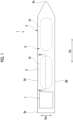
- a ship 1 which is a floating structure carries liquefied carbon dioxide.
- the ship 1 includes at least a hull 2 as a floating main structure and a tank facility 10.
- the hull 2 has a pair of sides 3A and 3B, a bottom (not shown), and an upper deck 5, which form an outer shell thereof.
- the sides 3A and 3B each have a pair of side shell platings which form the left and right sides.
- the bottom (not shown) has a bottom shell plating connecting the sides 3A and 3B to each other. Due to the pair of sides 3A and 3B and the bottom (not shown), the outer shell of the hull 2 has a U-shape in a cross section orthogonal to a stem-stern direction Da.
- the upper deck 5 shown in this embodiment is a continuous deck exposed to the outside.
- a superstructure 7 having an accommodation space is formed on the upper deck 5 on a stern 2b side.
- a cargo tank storage compartment (hold) 8 is formed on a stem 2a side of the superstructure 7.
- the cargo tank storage compartment 8 is recessed toward the bottom below the upper deck 5, and is open upward.
- a plurality of tank facilities 10 are disposed in the cargo tank storage compartment 8 along the stem-stern direction Da.
- two tank facilities 10 are disposed at intervals in the stem-stern direction Da.
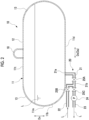
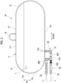
- the tank facility 10 includes at least a tank 11 and a lower pipe portion 20 connected to a lower portion 11b of the tank 11.
- the tank 11 is disposed on the hull 2.
- the tank 11 has, for example, a cylindrical shape extending in the horizontal direction.
- the tank 11 accommodates a liquefied carbon dioxide L inside thereof.
- the tank main body includes a tubular portion 12 and an end spherical portion 13.
- the tubular portion 12 extends in the horizontal direction as a longitudinal direction Dx.
- the tubular portion 12 is formed in a cylindrical shape having a circular cross-sectional shape orthogonal to the longitudinal direction Dx.
- the end spherical portions 13 are respectively disposed at both end portions of the tubular portion 12 in the longitudinal direction Dx.
- Each of the end spherical portions 13 has a hemispherical shape and blocks the openings at both ends of the tubular portion 12 in the longitudinal direction Dx.
- the tank 11 is not limited to a cylindrical shape, and the tank 11 may have a spherical shape, a square shape, or the like.
- the lower pipe portion 20 includes a connection pipe 21, a loading pipe 22, an unloading pipe 23, a pump 24, and switching valves 25A, 25B, and 25C.
- connection pipe 21 connects the tank 11, and the loading pipe 22 and the unloading pipe 23 to each other.
- One end 21a of the connection pipe 21 is connected to the lower portion 11b of the tank 11.
- the lower portion 11b of the tank 11 means a side lower than an intermediate position 11m in a vertical direction Dv of the tank 11.
- the one end 21a of the connection pipe 21 is connected to a bottom portion 11d including the lowermost portion of the tank 11.
- the one end 21a of the connection pipe 21 is connected to the bottom portion 11d of the tank 11 from below, which is the outside of the tank 11.
- the one end 21a of the connection pipe 21 is open in the tank 11 upward in the vertical direction Dv.
- the connection pipe 21 extends downward from the one end 21a connected to the bottom portion 11d of the tank 11.
- the position where the one end 21a of the connection pipe 21 is connected to the tank 11 is set at the lower portion 11b of the tank 11 and within a range that satisfies the following equation (1). h ⁇ Pt ⁇ TP ⁇ 1000 / ⁇ g
- connection pipe 21 The other end 21b of the connection pipe 21 is branched and connected to the loading pipe 22 and the unloading pipe 23.
- the loading pipe 22 is connected to a bottom portion 11d (lower portion 11b) of the tank 11 via the connection pipe 21.
- the loading pipe 22 loads the liquefied carbon dioxide L supplied from the outside of the hull 2 into the tank 11.
- the unloading pipe 23 is connected to the bottom portion 11d (lower portion 11b) of the tank 11 via the connection pipe 21.
- the unloading pipe 23 delivers the liquefied carbon dioxide L in the tank 11 to the outside of the hull 2, thereby unloading the liquefied carbon dioxide L in the tank 11.
- the pump 24 is disposed in the unloading pipe 23 outside the tank 11.
- the pump 24 sucks out the liquefied carbon dioxide L in the tank 11 through the unloading pipe 23 and the connection pipe 21, and delivers the liquefied carbon dioxide L to the outside of the hull 2.
- connection pipe 21, the loading pipe 22, and the unloading pipe 23, which forms the lower pipe portion 20 is not limited at all, but when the pipe top at the highest position in the middle of the connection pipe 21, the loading pipe 22, and the unloading pipe 23 is disposed at the highest position in the vertical direction Dv, the pressure of the liquefied carbon dioxide L at the pipe top becomes lower than the pressure of the liquefied carbon dioxide in the tank 11. Therefore, it is preferable that the entire connection pipe 21, the loading pipe 22, and the unloading pipe 23 be laid out at a position lower than the bottom portion 11d of the tank 11 as much as possible.
- the switching valve 25A is disposed in the connection pipe 21.
- the switching valve 25B is disposed in the loading pipe 22.
- the switching valve 25C is disposed in the unloading pipe 23.
- the switching valves 25A, 25B, and 25C selectively switch the connection destination of the connection pipe 21 to either the loading pipe 22 or the unloading pipe 23.
- the loading pipe 22 is connected to the connection pipe 21 by opening the switching valve 25A and the switching valve 25B and closing the switching valve 25C.
- the unloading pipe 23 is connected to the connection pipe 21 by opening the switching valve 25A and the switching valve 25C and closing the switching valve 25B.
- a dome structure 18 is disposed at a top 11t of the tank 11.
- the dome structure 18 is disposed with a pipe (pipeline) for taking in and out carbon dioxide gas, a connecting portion of an instrumentation pipe (not shown) to the tank 11, and other equipment.
- Examples of various types of instrumentation include a gas component detection sensor in the tank 11.
- the loading pipe and the unloading pipe are required to be connected to the top of the tank.
- the connection position between the loading pipe 22 and the unloading pipe 23 is not limited to the top 11t of the tank 11. Therefore, the above configuration is feasible.
- the switching valve 25A and the switching valve 25B are opened and the switching valve 25C is closed.
- the loading pipe 22 communicates with the inside of the tank 11 via the connection pipe 21.
- the liquefied carbon dioxide L is loaded into the tank 11 from the outside of the ship through the loading pipe 22 and the connection pipe 21.
- the switching valve 25A and the switching valve 25C are opened and the switching valve 25B is closed.
- the unloading pipe 23 communicates with the inside of the tank 11 via the connection pipe 21.
- the pump 24 is operated to suck the liquefied carbon dioxide L in the tank 11 and delivers the liquefied carbon dioxide L to the outside of the ship.
- the loading pipe 22 and the unloading pipe 23 are connected to the lower portion 11b of the tank 11. Accordingly, compared to a case where the loading pipe 22 and the unloading pipe 23 are connected to the top 11t of the tank 11, the height of the highest position of the loading pipe 22 and the unloading pipe 23 can be suppressed.
- the pressure of the liquefied carbon dioxide L at the highest position of the loading pipe 22 and the unloading pipe 23 is higher than the pressure of the liquefied carbon dioxide L stored in the tank 11. Therefore, the pressure drop of the liquefied carbon dioxide L at the highest position of the loading pipe 22 and the unloading pipe 23 is suppressed.
- the loading pipe 22 and the unloading pipe 23 are connected to the lower portion 11b of the tank 11, it is not necessary to connect the loading pipe 22 and the unloading pipe 23 to the dome structure 18 disposed at the top 11t of the tank 11. Accordingly, in order to increase the operating pressure of the tank 11, the size of the dome structure 18 can be reduced and the strength of the tank 11 structure can be increased. Further, it is not necessary to dispose the loading pipe 22 and the unloading pipe 23 in the tank 11 from the top 11t to the bottom portion 11d. Therefore, it is not necessary to provide the support structure for supporting the loading pipe 22 and the unloading pipe 23 in the tank 11. In addition, the pump 24 can be provided in the middle of a pipe disposed outside the tank 11. Therefore, maintenance of the pump 24 can be performed outside the tank 11. Therefore, the maintainability of the pump 24 is improved.
- the loading pipe 22 and the unloading pipe 23 are connected to the lower portion 11b of the tank 11 through the connection pipe 21. Therefore, compared to a configuration in which both the loading pipe 22 and the unloading pipe 23 are directly connected to the lower portion 11b of the tank 11, only one connection pipe 21 may be connected to the lower portion 11b of the tank 11, and the pipe connection work can be easily performed.
- the work of connecting the loading pipe 22 and the unloading pipe 23 to the connection pipe 21 can be performed outside the tank 11. Also in this respect, the pipe connection work can be easily performed.
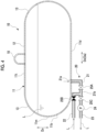
- connection pipe 21 is connected to the bottom portion 11d of the tank 11 from the outside of the tank 11 and is open upward in the tank 11.
- the liquefied carbon dioxide L in the tank 11 flows into the unloading pipe 23 from the opening of the one end 21a of the connection pipe 21 through the connection pipe 21 due to its own weight. Therefore, the liquefied carbon dioxide L in the tank 11 can be efficiently discharged.
- the one end 21a of the connection pipe 21 is connected to the bottom portion 11d of the tank 11, but the present disclosure is not limited thereto.
- the one end 21a of the connection pipe 21 is the lower portion 11b of the tank 11, the one end 21a may be disposed at a position above the bottom portion 11d. Also in this case, it is preferable to set the connection position of the connection pipe 21 such that the above equation (1) is satisfied.
- connection position of the connection pipe 21B to the tank 11 may be the lower portion 11b of the tank 11 and may be above the bottom portion 11d.
- the height h of the connection position of the connection pipe 21B to the tank 11 satisfies the above equation (1).
- the connection pipe 21B may be extended downward in the tank 11 and a tip portion 21s may be disposed in the vicinity of the bottom portion 11d in the tank 11. Accordingly, when the liquefied carbon dioxide L in the tank 11 is unloaded through the unloading pipe 23, the amount of the liquefied carbon dioxide L remaining in the tank 11 after the unloading is completed is suppressed.
- the loading pipe 22 and the unloading pipe 23 are connected to the lower portion 11b (bottom portion 11d) of the tank 11 through the connection pipe 21, but the present disclosure is not limited thereto.
- the loading pipe 22 and the unloading pipe 23 may be directly connected to the tank 11, respectively.
- a case where the loading pipe 22 is disposed above the unloading pipe 23 is shown in Fig. 2 , but the positional relationship between the loading pipe 22 and the unloading pipe 23 in the vertical direction is not limited to such a positional relationship.
- the loading pipe 22 may be disposed below the unloading pipe 23, or the loading pipe 22 and the unloading pipe 23 may be disposed to overlap each other when viewed from the horizontal direction.
- the number and arrangement of the tank facilities 10 are not limited to the number and arrangement shown in the above embodiment.
- only one tank facility 10 may be provided, or three or more tank facilities 10 may be provided.
- the tank facilities 10 may be disposed side by side in the ship width direction (in other words, the left-right side direction).
- the ship 1 is exemplified as the floating structure, but the present disclosure is not limited thereto.
- the floating structure may be an offshore floating structure facility that does not include a propulsion mechanism.
- the floating structure 1 described in the embodiment is ascertained as follows, for example.
- Examples of the floating structure 1 include a ship and an offshore floating structure facility.
- Examples of the floating main structure 2 include a floating main structure of a hull or an offshore floating structure facility.
- the loading pipe 22 and the unloading pipe 23 are connected to the lower portion 11b of the tank 11. Accordingly, compared to a case where the loading pipe 22 and the unloading pipe 23 are connected to the inside of the tank 11 from the upper portion of the tank 11, the height of the highest position of the loading pipe 22 and the unloading pipe 23 can be suppressed. Therefore, the approach of the pressure of the liquefied carbon dioxide L at the highest position of the loading pipe 22 and the unloading pipe 23 to the triple point pressure is suppressed. Accordingly, the solidification of the liquefied carbon dioxide L and the formation of dry ice in the loading pipe 22 and the unloading pipe 23 are suppressed.
- the loading pipe 22 and the unloading pipe 23 are connected to the lower portion 11b of the tank 11, it is not necessary to dispose the loading pipe 22 and the unloading pipe 23 in the dome structure 18 disposed at the top 11t of the tank 11. Accordingly, in order to increase the operating pressure of the tank 11, the size of the dome structure 18 can be reduced and the strength of the tank 11 structure can be increased. Further, it is not necessary to dispose the loading pipe 22 and the unloading pipe 23 in the tank 11 from the top 11t to the bottom portion 11d. Therefore, the necessity of providing a support member or the like for supporting the loading pipe 22 and the unloading pipe 23 in the tank 11 is suppressed.
- the pump 24 is disposed outside the tank 11. Therefore, maintenance of the pump 24 can be performed outside the tank 11. Therefore, the maintainability of the pump 24 is improved.
- a pump generally applied in an on-land liquefied carbon dioxide facility such as a centrifugal pump or a reciprocating pump, which is cheaper than a deep well pump installed in the tank 11, can be used. Therefore, there is an advantage that the choice of the type of pump is increased and the degree of design freedom can be improved.
- the floating structure 1 which is the floating structure 1 of (1) further including: the connection pipe 21 having one end 21a connected to the lower portion 11b of the tank 11 and the other end 21b connected to the loading pipe 22 and the unloading pipe 23; and the switching valves 25A, 25B, and 25C that selectively switches a connection destination of the connection pipe 21 to any one of the loading pipe 22 and the unloading pipe 23, the loading pipe 22 and the unloading pipe 23 are connected to the lower portion 11b of the tank 11 via the connection pipe 21.
- the loading pipe 22 and the unloading pipe 23 are connected to the lower portion 11b of the tank 11 through the connection pipe 21. Therefore, compared to a configuration in which both the loading pipe 22 and the unloading pipe 23 are directly connected to the lower portion 11b of the tank 11, only the connection pipe 21 may be connected to the lower portion 11b of the tank 11, and the pipe connection work can be easily performed.
- the work of connecting the loading pipe 22 and the unloading pipe 23 to the connection pipe 21 can be performed outside the tank 11. Also in this respect, the pipe connection work can be easily performed.
- the one end 21a of the connection pipe 21 is connected to the bottom portion 11d of the tank 11 from the outside of the tank 11 and is open upward in the tank 11.
- the liquefied carbon dioxide L in the tank 11 flows into the unloading pipe 23 from the opening of the one end 21a of the connection pipe 21 through the connection pipe 21 due to its own weight. Accordingly, the liquefied carbon dioxide L in the tank 11 can be efficiently discharged.
- the floating structure of the present disclosure it is possible to suppress the formation of dry ice in the loading pipe and the unloading pipe, and to achieve the reduction of the size of the dome structure, the simplification of the pipe structure, and the facilitation of maintenance.
Landscapes
- Engineering & Computer Science (AREA)
- Mechanical Engineering (AREA)
- General Engineering & Computer Science (AREA)
- Chemical & Material Sciences (AREA)
- Combustion & Propulsion (AREA)
- Ocean & Marine Engineering (AREA)
- Physics & Mathematics (AREA)
- Thermal Sciences (AREA)
- Filling Or Discharging Of Gas Storage Vessels (AREA)
- Artificial Filaments (AREA)
Applications Claiming Priority (2)
| Application Number | Priority Date | Filing Date | Title |
|---|---|---|---|
| JP2020180558A JP7580241B2 (ja) | 2020-10-28 | 2020-10-28 | 浮体 |
| PCT/JP2021/039905 WO2022092234A1 (fr) | 2020-10-28 | 2021-10-28 | Corps flottant |
Publications (2)
| Publication Number | Publication Date |
|---|---|
| EP4197894A1 true EP4197894A1 (fr) | 2023-06-21 |
| EP4197894A4 EP4197894A4 (fr) | 2024-01-24 |
Family
ID=81382583
Family Applications (1)
| Application Number | Title | Priority Date | Filing Date |
|---|---|---|---|
| EP21886351.2A Pending EP4197894A4 (fr) | 2020-10-28 | 2021-10-28 | Corps flottant |
Country Status (6)
| Country | Link |
|---|---|
| EP (1) | EP4197894A4 (fr) |
| JP (1) | JP7580241B2 (fr) |
| KR (1) | KR20230042516A (fr) |
| CN (1) | CN116113574A (fr) |
| AU (1) | AU2021369256B2 (fr) |
| WO (1) | WO2022092234A1 (fr) |
Families Citing this family (1)
| Publication number | Priority date | Publication date | Assignee | Title |
|---|---|---|---|---|
| JP2025002655A (ja) * | 2023-06-23 | 2025-01-09 | 三菱造船株式会社 | 船舶、船舶の二酸化炭素荷役方法 |
Family Cites Families (9)
| Publication number | Priority date | Publication date | Assignee | Title |
|---|---|---|---|---|
| JP3970073B2 (ja) | 2002-03-27 | 2007-09-05 | 三井造船株式会社 | ガスハイドレートペレット輸送船 |
| JP4209728B2 (ja) | 2003-07-03 | 2009-01-14 | 株式会社ササクラ | バラスト水の処理方法及び装置 |
| JP2008239097A (ja) | 2007-03-28 | 2008-10-09 | Mitsui Eng & Shipbuild Co Ltd | 液体運搬船 |
| KR20100125624A (ko) * | 2009-05-21 | 2010-12-01 | 대우조선해양 주식회사 | 이산화탄소와 천연가스를 운반하는 겸용 선박의 이송탱크 저압방지시스템 |
| KR20110126773A (ko) * | 2010-05-18 | 2011-11-24 | 대우조선해양 주식회사 | 부유식 구조물의 액화가스 로딩장치 |
| KR20120094682A (ko) * | 2011-02-17 | 2012-08-27 | 삼성중공업 주식회사 | 부유식 구조물 |
| JP5833070B2 (ja) | 2013-09-10 | 2015-12-16 | 中国電力株式会社 | 異種lng受入装置および異種lng受入方法 |
| EP3356723B1 (fr) | 2015-09-28 | 2019-12-11 | Wärtsilä Finland Oy | Agencement de réservoir de carburant d'un navire |
| JP2020180558A (ja) | 2019-04-24 | 2020-11-05 | 木村 光照 | 折畳可能な波力発電装置 |
-
2020
- 2020-10-28 JP JP2020180558A patent/JP7580241B2/ja active Active
-
2021
- 2021-10-28 AU AU2021369256A patent/AU2021369256B2/en active Active
- 2021-10-28 CN CN202180055093.6A patent/CN116113574A/zh active Pending
- 2021-10-28 KR KR1020237007485A patent/KR20230042516A/ko not_active Application Discontinuation
- 2021-10-28 WO PCT/JP2021/039905 patent/WO2022092234A1/fr unknown
- 2021-10-28 EP EP21886351.2A patent/EP4197894A4/fr active Pending
Also Published As
| Publication number | Publication date |
|---|---|
| EP4197894A4 (fr) | 2024-01-24 |
| AU2021369256B2 (en) | 2024-06-13 |
| AU2021369256A1 (en) | 2023-04-06 |
| WO2022092234A1 (fr) | 2022-05-05 |
| JP7580241B2 (ja) | 2024-11-11 |
| JP2022071533A (ja) | 2022-05-16 |
| CN116113574A (zh) | 2023-05-12 |
| KR20230042516A (ko) | 2023-03-28 |
Similar Documents
| Publication | Publication Date | Title |
|---|---|---|
| KR102490542B1 (ko) | 로딩/언로딩 타워가 장착된 밀폐 및 단열 탱크 | |
| US9933117B2 (en) | Cryogenic tank arrangement and a marine vessel provided with the same | |
| CN104159816B (zh) | 浮体 | |
| CN106163913A (zh) | 带有用于液态气体的燃料箱的船 | |
| EP4197894A1 (fr) | Corps flottant | |
| KR20170130536A (ko) | 선박용 액화가스 탱크 및 그것을 구비하는 액화가스 운반선 | |
| EP4194329A1 (fr) | Corps flottant, procédé de chargement de dioxyde de carbone liquéfié, et procédé de déchargement de dioxyde de carbone liquéfié | |
| CN114127464A (zh) | 罐装置 | |
| KR20210093751A (ko) | 액화 가스 연료선 | |
| US9132892B2 (en) | Floating vessel with tunnel | |
| KR20190078923A (ko) | Lng 연료 선박 | |
| CN114787028B (zh) | 船舶 | |
| KR20210129168A (ko) | 선박 | |
| US10081412B2 (en) | Floating vessel with tank trough deck | |
| JP2018134940A (ja) | 自動車運搬船のガス燃料独立タンク設置構造 | |
| KR102110641B1 (ko) | 안티 힐링 시스템 및 이를 구비하는 선박 | |
| EP4215798A1 (fr) | Procédé de transfert de dioxyde de carbone liquéfié, et corps flottant | |
| JP7595612B2 (ja) | 浮体、液化二酸化炭素の積込方法 | |
| WO2020075633A1 (fr) | Procédé d'utilisation pour navires existants, procédé de production pour installation de stockage flottante, et installation de stockage flottante | |
| KR20240062621A (ko) | 부유식 구조물 | |
| KR20130012355A (ko) | 유동 차단용 기구를 갖는 횡동요 저감 탱크 및 이를 가지는 해상 구조물 |
Legal Events
| Date | Code | Title | Description |
|---|---|---|---|
| STAA | Information on the status of an ep patent application or granted ep patent |
Free format text: STATUS: THE INTERNATIONAL PUBLICATION HAS BEEN MADE |
|
| PUAI | Public reference made under article 153(3) epc to a published international application that has entered the european phase |
Free format text: ORIGINAL CODE: 0009012 |
|
| STAA | Information on the status of an ep patent application or granted ep patent |
Free format text: STATUS: REQUEST FOR EXAMINATION WAS MADE |
|
| 17P | Request for examination filed |
Effective date: 20230317 |
|
| AK | Designated contracting states |
Kind code of ref document: A1 Designated state(s): AL AT BE BG CH CY CZ DE DK EE ES FI FR GB GR HR HU IE IS IT LI LT LU LV MC MK MT NL NO PL PT RO RS SE SI SK SM TR |
|
| A4 | Supplementary search report drawn up and despatched |
Effective date: 20240103 |
|
| RIC1 | Information provided on ipc code assigned before grant |
Ipc: F17C 9/00 20060101ALI20231220BHEP Ipc: F17C 6/00 20060101ALI20231220BHEP Ipc: F17C 3/02 20060101ALI20231220BHEP Ipc: F17C 13/00 20060101ALI20231220BHEP Ipc: B63B 27/24 20060101ALI20231220BHEP Ipc: B63B 25/16 20060101ALI20231220BHEP Ipc: B63B 25/08 20060101AFI20231220BHEP |
|
| DAV | Request for validation of the european patent (deleted) | ||
| DAX | Request for extension of the european patent (deleted) |