EP4195894A1 - Heat dissipation device and manufacturing method therefor - Google Patents
Heat dissipation device and manufacturing method therefor Download PDFInfo
- Publication number
- EP4195894A1 EP4195894A1 EP21859805.0A EP21859805A EP4195894A1 EP 4195894 A1 EP4195894 A1 EP 4195894A1 EP 21859805 A EP21859805 A EP 21859805A EP 4195894 A1 EP4195894 A1 EP 4195894A1
- Authority
- EP
- European Patent Office
- Prior art keywords
- heat dissipation
- pts
- structures
- bottom substrate
- top layer
- Prior art date
- Legal status (The legal status is an assumption and is not a legal conclusion. Google has not performed a legal analysis and makes no representation as to the accuracy of the status listed.)
- Pending
Links
Images

Classifications
-
- H—ELECTRICITY
- H05—ELECTRIC TECHNIQUES NOT OTHERWISE PROVIDED FOR
- H05K—PRINTED CIRCUITS; CASINGS OR CONSTRUCTIONAL DETAILS OF ELECTRIC APPARATUS; MANUFACTURE OF ASSEMBLAGES OF ELECTRICAL COMPONENTS
- H05K7/00—Constructional details common to different types of electric apparatus
- H05K7/20—Modifications to facilitate cooling, ventilating, or heating
- H05K7/20845—Modifications to facilitate cooling, ventilating, or heating for automotive electronic casings
- H05K7/20881—Liquid coolant with phase change
-
- H—ELECTRICITY
- H05—ELECTRIC TECHNIQUES NOT OTHERWISE PROVIDED FOR
- H05K—PRINTED CIRCUITS; CASINGS OR CONSTRUCTIONAL DETAILS OF ELECTRIC APPARATUS; MANUFACTURE OF ASSEMBLAGES OF ELECTRICAL COMPONENTS
- H05K7/00—Constructional details common to different types of electric apparatus
- H05K7/20—Modifications to facilitate cooling, ventilating, or heating
- H05K7/20845—Modifications to facilitate cooling, ventilating, or heating for automotive electronic casings
- H05K7/20854—Heat transfer by conduction from internal heat source to heat radiating structure
-
- Y—GENERAL TAGGING OF NEW TECHNOLOGICAL DEVELOPMENTS; GENERAL TAGGING OF CROSS-SECTIONAL TECHNOLOGIES SPANNING OVER SEVERAL SECTIONS OF THE IPC; TECHNICAL SUBJECTS COVERED BY FORMER USPC CROSS-REFERENCE ART COLLECTIONS [XRACs] AND DIGESTS
- Y02—TECHNOLOGIES OR APPLICATIONS FOR MITIGATION OR ADAPTATION AGAINST CLIMATE CHANGE
- Y02D—CLIMATE CHANGE MITIGATION TECHNOLOGIES IN INFORMATION AND COMMUNICATION TECHNOLOGIES [ICT], I.E. INFORMATION AND COMMUNICATION TECHNOLOGIES AIMING AT THE REDUCTION OF THEIR OWN ENERGY USE
- Y02D10/00—Energy efficient computing, e.g. low power processors, power management or thermal management
Definitions
- This application relates to the field of hardware heat dissipation technologies, and more specifically, to a heat dissipation apparatus and a manufacturing method thereof.
- a heat dissipation problem of these electronic devices in an operating process thus becomes prominent.
- a conventional vehicle-mounted radiator is usually a dust-proof, water-proof, and corrosion-resistant aluminum radiator.
- Some electronic devices with low power consumption may use natural heat dissipation, whereas some electronic devices with high power consumption use air-cooled heat dissipation.
- power consumption of electronic devices in a vehicle increases by dozens of times. In this case, a heat exchange area of the conventional vehicle-mounted radiator is obviously insufficient.
- a height of a fin of the radiator needs to be increased.
- a larger height of the fin indicates a larger temperature difference between a bottom and a top of the fin.
- a heat exchange effect in a top area of the fin is quite poor, resulting in poor overall utilization efficiency of the fin and failure to meet a required heat dissipation effect.
- This application provides a heat dissipation apparatus and a manufacturing method thereof, to effectively improve a heat dissipation effect of the heat dissipation apparatus.
- a heat dissipation apparatus includes a top layer, a plurality of plate thermos syphon PTS structures, and a bottom substrate.
- the top layer and the bottom substrate are disposed in parallel, the PTS structures are disposed between the top layer and the bottom substrate and are perpendicular to the bottom substrate, and a first end of the PTS structure is fastened on a surface that faces the top layer and that is of the bottom substrate.
- the top layer includes a first cover plate, a second cover plate, and a first cavity located between the first cover plate and the second cover plate.
- the PTS structure includes side walls and a second cavity enclosed by the side walls, and the side walls are connected to the second cover plate, to enable the second cavities of the plurality of PTS structures to communicate through the first cavity.
- the second cavity contains a refrigerant.
- the side walls and the bottom substrate are made of a thermally conductive metal material.
- heat dissipation is performed in a two-phase heat exchange manner by using the PTS structure that is a special heat dissipation structure.
- An equivalent thermal conductivity coefficient (approximately 1000 W/mk to 20000 W/mk) of the PTS structure in a height direction (a direction from the bottom substrate to the top layer) is far greater than a thermal conductivity coefficient (approximately 100 W/mk to 200 W/mk) of conventional air-cooled metal fins. Therefore, a heat dissipation effect of the heat dissipation apparatus can be significantly improved.
- the heat dissipation apparatus in this embodiment of this application implements heat exchange through a phase change. Therefore, compared with a conventional air-cooled radiator conventional air cooling, the heat dissipation apparatus has quite little noise and is more suitable for a relatively closed environment such as a vehicle, improving users' use comfort.
- the heat dissipation apparatus in this embodiment of this application is made of a metal material such as aluminum flakes. When providing a same heat dissipation effect, the heat dissipation apparatus is far lighter than a conventional air-cooled radiator.
- the heat dissipation apparatus in this embodiment of this application has a far lower requirement for thermal conductivity of a metal material than the conventional air-cooled radiator. Therefore, a relatively economical metal material may be selected for manufacturing, effectively reducing costs.
- the first cover plate and the second cover plate may alternatively not be used for heat dissipation.
- the first cover plate and the second cover plate may not even be required to be thermally conductive, or they may not use a metal material. Therefore, in this case, steam mainly performs heat exchange with surfaces of the side walls in a rising process.
- the top layer may be made also available for heat dissipation.
- the first cover plate and the second cover plate may be made available for heat dissipation.
- the top layer is made of the thermally conductive metal material.
- the PTS structures and the bottom substrate may be made of the thermally conductive metal material, for example, pure metal such as aluminum, copper, or iron, or an alloy material such as an aluminum alloy, a copper alloy, or steel.
- materials used by different components may be the same or different.
- the top layer, the side walls of the PTS structures, and the bottom substrate may use a same metal material, or may use different metal materials, provided that a thermally conductive metal material is used.
- a corrosion-resistant metal material such as aluminum, copper, an aluminum alloy, or a copper alloy may be further selected to make the PTS structures and the bottom substrate.
- the metal material may include at least one of the following: aluminum, copper, an aluminum alloy, or a copper alloy.
- a folded fin may be further disposed between at least two of the plurality of PTS structures to increase a heat exchange area, improving heat exchange efficiency.
- the heat dissipation apparatus further includes a folded fin.
- the folded fin is connected between at least two adjacent PTS structures of the plurality of PTS structures.
- the folded fin is made of the thermally conductive metal material.
- the folded fin may be connected to the side walls in a welding manner.
- the folded fin may be made of the thermally conductive metal material, for example, pure metal such as aluminum, copper, or iron, or an alloy material such as an aluminum alloy, a copper alloy, or steel.
- a corrosion-resistant metal material such as aluminum, copper, an aluminum alloy, or a copper alloy may be further selected as a material for making the folded fin.
- the folded fin may be of different shapes (structures), provided that the folded fin can be connected to the side walls of the plurality of PTS structures to increase a heat exchange area.
- refrigerant substances such as tetrafluoroethane (R134), difluoromethane (R32), and pentafluoroethane (R125) may be selected as the refrigerant, or a refrigerant made from a mixture of a plurality of refrigerant substances, such as R410 (which is made from a mixture of R32 and R125), may be selected. Examples are not listed herein one by one.
- an environmentally friendly substance such as R134 may be selected as the refrigerant.
- a manufacturing method of a heat dissipation apparatus includes: clamping components of a heat dissipation apparatus together by using tooling, and applying welding flux to all contact parts; melting the welding flux to weld the components together, to form an overall frame structure with a cavity; injecting a refrigerant from a liquid injection port; and sealing the liquid injection port through welding.
- the heat dissipation apparatus may be any heat dissipation apparatus in the first aspect.
- the heat dissipation apparatus may include a top layer, a plurality of PTS structures, and a bottom substrate.
- the top layer and the bottom substrate are disposed in parallel, and the PTS structures are disposed between the top layer and the bottom substrate and are perpendicular to the bottom substrate.
- the PTS structure includes side walls and a second cavity enclosed by the side walls, and a first end of the side wall is in contact with the bottom substrate.
- a liquid injection port is disposed on the side wall of at least one of the plurality of PTS structures.
- the top layer includes a first cover plate and a second cover plate, both ends of the first cover plate are in contact with the second cover plate, a first cavity is formed between the first cover plate and the second cover plate, and the second cover plate is in contact with second ends of the side walls of each PTS structure, to enable the second cavities of the plurality of PTS structures to communicate with the first cavity.
- the top layer, the PTS structures, and the bottom substrate are made of a thermally conductive metal material.
- an overall frame of the heat dissipation apparatus can be integrally formed, and subsequently, only injecting a refrigerant and sealing the liquid injection port need to be performed. This is convenient to operate and easy to implement, both improving production efficiency and improving quality of production to some extent. Contact points do not need to be welded one by one, and operation, assembly, and the like also do not need to be performed for a plurality of times.
- the manufactured heat dissipation apparatus has a better heat dissipation effect than a conventional radiator.
- the metal material includes at least one of the following: aluminum, copper, an aluminum alloy, or a copper alloy.
- a melting point of the welding flux is lower than a melting point of the metal material used by the top layer, the PTS structures, and the bottom substrate.
- the refrigerant is made of a volatile refrigerant substance that is liquid at normal temperature.
- a conventional air-cooled radiator mainly rotates a fan to accelerate air circulation, to dissipate heat as quickly as possible. If a heat dissipation effect of the radiator is to be improved, the following several manners may be used for implementation.
- a first manner is to increase a rotational speed of the fan, to improve a heat exchange capability of the radiator.
- this improvement is not significant and may further cause a heating-up problem of the radiator.
- a second manner is to increase a thickness of a fin. After the thickness of the fin is increased, thermal conduction resistance from a bottom to a top of the fin decreases, a temperature difference decreases, but a weight of the radiator increases. In addition, after the thickness of the fin is increased, a quantity of fins decreases in a same area, and heat exchange performance of the radiator may not be improved but deteriorate.
- a third manner is to replace a material of a fan with a material with a larger thermal conductivity coefficient.
- a fan made of die casting aluminum (a type of aluminum alloy) with a thermal conductivity coefficient of 100 watts/meter ⁇ degree (W/mk) may be replaced with a fan made of machined aluminum 6061 (another type of aluminum alloy) with a thermal conductivity coefficient of 180 W/mk.
- W/mk die casting aluminum
- machined aluminum 6061 another type of aluminum alloy
- an embodiment of this application provides a heat dissipation apparatus in a new structural form, to effectively improve a heat dissipation effect.
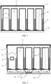
- FIG. 1 is a schematic diagram of a structure of a heat dissipation apparatus according to an embodiment of this application.
- the heat dissipation apparatus includes a top layer, a plurality of plate thermos syphon (plate thermos syphon, PTS) structures 20, and a bottom substrate 30.
- the top layer and the bottom substrate 30 are disposed in parallel.
- the plurality of PTS structures 20 are disposed between the top layer and the bottom substrate 30 and are perpendicular to the top layer and the bottom substrate 30.
- First ends of the plurality of PTS structures 20 are fastened on a surface (which may be understood as an upper surface of the bottom substrate 30) that faces the top layer and that is of the bottom substrate 30.
- the top layer includes a first cover plate 11, a second cover plate 12, and a first cavity (first hollow cavity) 13 located between the first cover plate 11 and the second cover plate 12.
- Each PTS structure 20 includes side walls 21 and a second cavity (second hollow cavity) 22 enclosed by the side walls 21.
- the side walls 21 of each of the plurality of PTS structures 20 are connected to the second cover plate 12, to enable the second cavity 22 of each PTS structure 20 to communicate with the first cavity 13.
- the plurality of second cavities 22 may communicate with each other through the first cavity 13.
- the side walls 21 may be made of a thermally conductive metal material, for example, pure metal such as aluminum, copper, or iron, or an alloy material such as an aluminum alloy, a copper alloy, or steel.
- a corrosion-resistant metal material such as aluminum, copper, an aluminum alloy, or a copper alloy may be further selected to make the side walls 21.
- an aluminum alloy may be further selected as a material for making the side walls 21.
- two aluminum flakes may be welded to form a hollow PTS structure.
- the heat dissipation apparatus in this embodiment of this application has a far lower requirement for a material than a conventional air-cooled radiator.
- the aluminum flakes need to be made of an expensive aluminum alloy material with a quite large thermal conductivity coefficient.
- a requirement for a thermal conductivity coefficient of the aluminum flakes is relatively low. Therefore, costs can be effectively reduced.
- first cover plate 11 and the second cover plate 12 may also be made of a metal material, may use a same material as the side walls 21, or may use a different material than the side walls 21. This is not limited. It should be further understood that in this embodiment of this application, the first cover plate 11 and the second cover plate 12 may alternatively not be used for heat dissipation. In this case, the first cover plate 11 and the second cover plate 12 may not even be required to be thermally conductive, or they may not use a metal material. However, using the first cover plate 11 and the second cover plate 12 for heat dissipation can further increase a heat exchange area, further improving a heat dissipation effect.
- first ends (bottoms of the side walls 21 shown in FIG. 1 ) of the side walls 21 and the bottom substrate 30 may be welded (for example, soldered) together for sealing.
- the first ends of the side walls 21 are fastened on the upper surface of the bottom substrate 30.
- the side walls 21 may be fastened on the upper surface of the bottom substrate 30 in a manner of welding, for example, soldering.
- the second cavities 22 may be filled with a volatile refrigerant 23.
- a refrigerant is a substance used by various cooling devices to complete energy conversion, and is also referred to as a working substance for completing a thermodynamic cycle.
- An energy conversion process is usually implemented through a phase change. For example, a phase change from a gas state to a liquid state releases a large amount of heat, whereas a phase change from the liquid state to the gas state absorbs a large amount of heat.
- a volatile refrigerant that is, a substance easy to perform a phase change from the liquid state to the gas state is selected.
- the refrigerant Under a normal condition (for example, at normal temperature), the refrigerant is in the liquid state, for example, the liquid refrigerant 23 shown in FIG. 1 .
- a bottom (an end close to the bottom substrate 30) of the PTS structure 20 is heated.
- a temperature of the refrigerant 23 rises, and a phase change occurs (from the liquid state to the gas state).
- the phase change process absorbs heat from the bottom (that is, heat transferred from the bottom substrate 30), playing a role of cooling and heat dissipation.
- FIG. 2 A specific process is described in FIG. 2 , and details are not described herein.
- refrigerant substances such as tetrafluoroethane (R134), difluoromethane (R32), and pentafluoroethane (R125) may be selected as the refrigerant, or a refrigerant made from a mixture of a plurality of refrigerant substances, such as R410 (which is made from a mixture of R32 and R125), may be selected. Examples are not listed herein one by one.
- an environmentally friendly substance such as R134 may be selected as the refrigerant.
- the bottom substrate 30 may be used to transfer heat of an object (which may be, for example, an electronic device whose heat is to be dissipated such as a device, a chip, or a component) that needs to be cooled to the PTS structures 20. Specifically, the bottom substrate 30 absorbs heat of an object to be cooled, and transfers the heat of the object to be cooled to the first ends of the side walls 21 of the PTS structures connected to the bottom substrate 30.
- an object which may be, for example, an electronic device whose heat is to be dissipated such as a device, a chip, or a component
- the bottom substrate 30 may be made of a thermally conductive metal material, for example, pure metal such as aluminum, copper, or iron, or an alloy material such as an aluminum alloy, a copper alloy, or steel.
- a corrosion-resistant metal material such as aluminum, copper, an aluminum alloy, or a copper alloy may be further selected to make the bottom substrate 30.
- a material of the bottom substrate 30 may be the same as or different from materials of other parts.
- the top layer, the side walls 21 of the PTS structures 20, and the bottom substrate 30 may use a same metal material, or may use different metal materials, provided that a thermally conductive metal material is used.
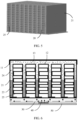
- FIG. 2 is a schematic diagram of a heat dissipation process of a heat dissipation apparatus according to an embodiment of this application.
- a surface (a lower surface of the bottom substrate 30) of a side that is far away from the top layer and that is of the bottom substrate 30 is pressed against an electronic device 40 whose heat is to be dissipated.
- the electronic device 40 whose heat is to be dissipated may be a device, a chip, a component, an electronic module, or the like.
- the heat dissipation apparatus in this embodiment of this application may be integrated inside some electronic devices whose heat needs to be dissipated, and be in contact with a module that is expected to be protected by cooling; or may be a separate heat dissipation apparatus, and only the bottom substrate 30 of the heat dissipation apparatus needs to be pressed against an area that emits heat.
- the following uses an example for description in which the electronic device 40 whose heat is to be dissipated is a chip.
- the lower surface of the bottom substrate 30 is pressed against a chip (an example of the electronic device 40 whose heat is to be dissipated), and the chip is located on a surface of a printed circuit board 50.
- the chip heats up (a temperature rises and is greater than a temperature of the bottom substrate 30)
- heat of the chip is transferred to the bottom substrate 30 through a physical contact surface of the lower surface of the bottom substrate 30, further transferred, through the bottom substrate 30, to the first ends of the side walls 21 connected to the bottom substrate 30, and then transferred to the refrigerant 23 in the second cavities 22.
- the refrigerant 23 evaporates quickly after being heated.
- the evaporation process absorbs heat.
- steam 24 of the refrigerant 23 is generated.
- the steam 24 performs heat exchange with surfaces of the side walls 21, a surface of the first cover plate 11, and a surface of the second cover plate 12. Heat is dissipated into air.
- the steam 24 liquefies, is re-converted into the refrigerant 23 that is in the liquid state, flows down to bottoms of the second cavities 22 along the surfaces of the side walls 21, that is, flows in a direction towards the bottom substrate 30, and finally melts into the original refrigerant 23, to enter a next round of heat exchange (gasification-liquefaction).
- temperatures of the steam 24 in the second cavities 22 can be enabled to tend to be consistent, effectively improving heat dissipation performance of the heat dissipation apparatus.
- the first cover plate 11 and the second cover plate 12 may alternatively not be used for heat dissipation.
- the first cover plate 11 and the second cover plate 12 may not even be required to be thermally conductive, or they may not use a metal material. Therefore, in this case, the steam 24 mainly performs heat exchange with the surfaces of the side walls 21 in the rising process.
- the heat dissipation apparatus in this embodiment of this application performs heat dissipation in a two-phase heat exchange manner by using the PTS structure that is a special heat dissipation structure.
- An equivalent thermal conductivity coefficient (approximately 1000 W/mk to 20000 W/mk) of the PTS structure in a height direction (a direction from the bottom substrate 30 to the top layer) is far greater than a thermal conductivity coefficient (approximately 100 W/mk to 200 W/mk) of conventional air-cooled metal fins. Therefore, the heat dissipation effect of the heat dissipation apparatus can be significantly improved.
- the heat dissipation apparatus in this embodiment of this application implements heat exchange through a phase change. Therefore, compared with a conventional air-cooled radiator, the heat dissipation apparatus has quite little noise and is more suitable for a relatively closed environment such as a vehicle, improving users' use comfort.
- the heat dissipation apparatus in this embodiment of this application is made of a metal material such as aluminum flakes. When providing a same heat dissipation effect, the heat dissipation apparatus is far lighter than a conventional air-cooled radiator.
- the heat dissipation apparatus in this embodiment of this application has a far lower requirement for thermal conductivity of a metal material than the conventional air-cooled radiator. Therefore, a relatively economical metal material may be selected for manufacturing, effectively reducing costs.
- a folded fin may be further disposed between at least two of the plurality of PTS structures 20 to increase the heat exchange area, improving heat exchange efficiency.
- FIG. 3 is a schematic diagram of a structure of a heat dissipation apparatus according to an embodiment of this application.
- the heat dissipation apparatus includes a top layer, a plurality of PTS structures 20, and a bottom substrate 30.
- a folded fin 25 is connected between at least two adjacent PTS structures of the plurality of PTS structures 20, so that the folded fin 25 can perform heat transfer with connected side walls 21.
- FIG. 3 is compared with FIG. 1 , only the folded fin 25 is added, and other structures are exactly the same. Therefore, for brevity, appropriate omission is made.
- content of an omitted part refer to related descriptions in FIG. 1 and FIG. 2 .
- the folded fin (folded fin) 25 connects side walls 21 of two PTS structures, increasing a heat exchange area.
- heat of the side walls 21 can be transferred to the folded fin 25 and then dissipated through the folded fin 25.
- the folded fin 25 may be connected to the side walls 21 in a welding manner.
- the folded fin 25 may be made of a thermally conductive metal material, for example, pure metal such as aluminum, copper, or iron, or an alloy material such as an aluminum alloy, a copper alloy, or steel.
- a corrosion-resistant metal material such as aluminum, copper, an aluminum alloy, or a copper alloy may be further selected as a material for making the folded fin 25.
- the folded fin 25 may be of different shapes (structures), provided that the folded fin 25 can be connected to the side walls 21 of the plurality of PTS structures to increase the heat exchange area.
- a quantity of folds of the folded fin 25 may be increased, or it may be understood as that the folded fin 25 may have a plurality of segments that are in contact with the side walls 21. As shown in FIG. 3 , each transverse structure that is connected between two side walls 21 and that is in the folded fin 25 may be considered as a fold. An increase in a quantity of folds may lead to an increase in the heat exchange area. However, it should be noted that excessive folds also affect a heat dissipation effect. Therefore, the quantity of folds needs to be increased within a specific range.
- a thermal conductivity coefficient of the fin can be increased by 5.6 to 111.1 times, a temperature difference (a difference between temperatures of two ends of the fin) of the fin is reduced from 9 degrees Celsius (°C) to less than 1.3°C, and heat dissipation performance is improved by more than 40%.
- FIG. 4 is a schematic diagram of several examples of a structure of a folded fin 25.
- a folded fin 25 shown in (a) in FIG. 4 is of an arcuate structure.
- a folded fin 25 shown in (b) in FIG. 4 is of a zigzag structure.
- a folded fin 25 shown in (c) in FIG. 4 is of a parabolic (or may be considered as semicircular) structure.
- a folded fin 25 shown in (d) in FIG. 4 is of an irregular wavy structure.
- a folded fin 25 shown in (e) in FIG. 4 is of a trapezoidal structure.
- a shape of the folded fin 25 is not limited in this embodiment of this application. However, selecting a regular shape makes it easy to process. For example, a shape in (a), (b), (c), or (e) in FIG. 4 may be selected.
- the folded fins 25 in the two solutions of (a) and (e) in FIG. 4 have a relatively large area that is in contact with side walls 21. When the folded fins 25 in the two solutions of (a) and (e) are compared with the folded fins 25 in the three solutions of (b), (c), and (d), it is easier to transfer heat from the side walls 21 to the folded fins 25 in the two solutions of (a) and (e).
- FIG. 5 is a schematic diagram of a three-dimensional structure of PTS structures 20 and folded fins 25.
- a shape of the folded fin 25 in FIG. 5 corresponds to a shape shown in (a) in FIG. 4 .
- every two adjacent PTS structures 20 are connected by using the folded fin 25.
- the folded fin 25 is connected to both opposite side walls 21 of every two adjacent PTS structures 20.
- FIG. 6 is a schematic diagram of a heat dissipation process of a heat dissipation apparatus according to an embodiment of this application. It should be noted that when FIG. 6 is compared with FIG. 2 , only the folded fin 25 is added, and other structures are exactly the same. Therefore, for brevity, appropriate omission is made. For content of an omitted part, refer to related descriptions in FIG. 2 .
- the following uses an example for description in which the electronic device 40 whose heat is to be dissipated is a chip.
- a lower surface of the bottom substrate 30 is pressed against a chip (an example of the electronic device 40 whose heat is to be dissipated), and the chip is located on a surface of a printed circuit board 50.
- heat of the chip is transferred to the bottom substrate 30 through a physical contact surface of the lower surface of the bottom substrate 30, further transferred, through the bottom substrate 30, to first ends of the side walls 21 connected to the bottom substrate, and then transferred to a refrigerant 23 in second cavities 22.
- the refrigerant 23 evaporates quickly after being heated.
- the evaporation process absorbs heat.
- steam 24 of the refrigerant 23 is generated.
- the steam 24 performs heat exchange with surfaces of the side walls 21, a surface of a first cover plate 11, and a surface of a second cover plate 12. Heat is dissipated into air.
- temperatures of the steam 24 in the second cavities 22 can be enabled to tend to be consistent, effectively improving heat dissipation performance of the heat dissipation apparatus.
- the first cover plate 11 and the second cover plate 12 may alternatively not be used for heat dissipation.
- the first cover plate 11 and the second cover plate 12 may not even be required to be thermally conductive, or they may not use a metal material. Therefore, in this case, in the rising process, the steam 24 mainly performs heat exchange with the surfaces of the side walls 21, and dissipates heat through the folded fin 25 connected to the side walls 21.
- This application provides a manufacturing method of a heat dissipation apparatus, capable of forming a heat dissipation apparatus at one time and effectively improving production efficiency.
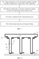
- FIG. 7 is a schematic flowchart of a manufacturing process of a heat dissipation apparatus according to an embodiment of this application. The following describes steps in FIG. 7 . It should be noted that for ease of understanding the steps in the manufacturing process described in FIG. 7 , a description is provided with reference to FIG. 8 to FIG. 11. FIG. 8 to FIG. 11 show structures of the heat dissipation apparatus and states of components in different manufacturing steps.
- 701 Clamp the components of the heat dissipation apparatus together, and apply welding flux to contact parts of the components.
- the components of the heat dissipation apparatus include a top layer, a plurality of PTS structures, and a bottom substrate 130.
- the top layer and the bottom substrate 130 are disposed in parallel.
- the plurality of PTS structures are disposed between the top layer and the bottom substrate 130 and are perpendicular to the top layer and the bottom substrate 130.
- First ends of the plurality of PTS structures are in contact with a surface (which may be understood as an upper surface of the bottom substrate 30) that faces the top layer and that is of the bottom substrate 130.
- Each of the plurality of PTS structures includes side walls 121 and a second cavity 122 enclosed by the side walls 121.
- a first end (an end close to the bottom substrate 130) of the side wall 121 is in contact with the bottom substrate 130.
- a liquid injection port 102 is disposed on the side wall 121 of at least one of the plurality of PTS structures.
- FIG. 8 to FIG. 10 show cases that exist when there is only one liquid injection port 102.
- FIG. 11 and FIG. 12 show cases that exist when there are a plurality of liquid injection ports 102.
- the liquid injection port may be disposed on only one PTS structure, and liquid can be injected into each PTS structure because a first cavity and the second cavities communicate with each other.
- disposing a plurality of liquid injection ports or even separately disposing a liquid injection port on each PTS structure makes it more convenient to inject the liquid (inject a refrigerant).
- the top layer includes a first cover plate 111 and a second cover plate 112. Both ends of the first cover plate 11 are in contact with the second cover plate 112.
- the first cavity may be formed between the first cover plate 111 and the second cover plate 112.
- the second cover plate 112 is in contact with second ends (ends far away from the bottom substrate 30) of the side walls 121 of each PTS structure, to enable the second cavity of each PTS structure to separately communicate with the first cavity in the top layer.
- the components may be clamped together by using tooling.
- welding flux for example, solder
- each gray oval indicates the welding flux 101.
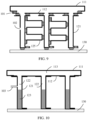
- FIG. 8 and FIG. 9 are schematic diagrams of structures of components of a heat dissipation apparatus in a manufacturing process according to an embodiment of this application.
- the heat dissipation apparatus in FIG. 8 does not include a folded fin
- the heat dissipation apparatus in FIG. 9 includes a folded fin 125.
- all components of the heat dissipation apparatus may be clamped together, and the welding flux may be applied to each contact part in Step 701.
- This manufacturing manner can make a frame of the heat dissipation apparatus to be integrally formed, both improving production efficiency and improving quality of production to some extent.
- FIG. 9 differs from FIG. 8 only in that the folded fin 125 is added between at least two adjacent PTS structures of a plurality of PTS structures, and the folded fin 125 is in contact with side walls 121 of the at least two adjacent PTS structures at a plurality of points. Therefore, when the welding flux is applied, the welding flux is also applied to these contact parts, as shown in FIG. 9 .
- the components may use any of thermally conductive metal materials described above.
- the components may use materials with good corrosion resistance such as aluminum, copper, an aluminum alloy, and a copper alloy.
- materials with good corrosion resistance such as aluminum, copper, an aluminum alloy, and a copper alloy.
- the aluminum alloy may be further selected from the materials.
- the welding flux 101 may also use a thermally conductive metal material.
- a melting temperature of the welding flux is lower than a melting temperature of each component.
- the components and the welding flux 101 may all use an aluminum alloy.
- a size of the heat dissipation apparatus in this embodiment of this application is not limited. For example, none of a height of the side wall of the PTS structure, a width of the top layer, or the like is limited, provided that the structure can be formed.
- the heat dissipation apparatus may be made small in size, whereas when the heat dissipation apparatus is used to dissipate heat for a large electronic device, a large size may be designed.
- the entire heat dissipation apparatus obtained after Step 701 is performed may be placed in a soldering furnace for heating, so that the welding flux melts and makes all the contact parts bond with their adjacent parts, to form the overall frame structure with the cavity.
- liquid injection pipe 103 is connected to the liquid injection port 102 to inject the refrigerant 123.
- liquid injection pipes 103 are connected to the plurality of liquid injection ports 102 to inject the refrigerant 123.
- FIG. 10 and FIG. 11 are schematic diagrams of injecting a refrigerant into cavities of a heat dissipation apparatus according to an embodiment of this application.
- FIG. 10 and FIG. 11 are mainly intended to describe liquid injection, whether the heat dissipation apparatus includes a folded fin is not limited.
- the heat dissipation apparatus shown in FIG. 10 has only one liquid injection port, but the heat dissipation apparatus may be the heat dissipation apparatus shown in FIG. 8 or the heat dissipation apparatus shown in FIG. 9 .
- the heat dissipation apparatus includes a plurality of liquid injection ports 102.
- the liquid injection pipe 103 may be connected to each liquid injection port 102 to inject the refrigerant.
- air in the cavities may be pumped out from the liquid injection port. This can improve a heat exchange effect.
- a liquid level of the refrigerant 123 is not higher than a height of the liquid injection port 102.
- a volume of the refrigerant 123 may be determined based on the height of the side wall 121.
- the liquid injection port 102 may be welded up, so that the cavities of the heat dissipation apparatus become a completely closed structure.
- each liquid injection port 102 may be sealed through welding by using the welding flux 101.
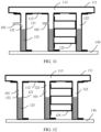
- FIG. 12 is a schematic diagram of sealing a liquid injection port according to an embodiment of this application.
- FIG. 12 may be considered as an operation that is further performed on a basis of FIG. 11 .
- each liquid injection port 102 is sealed by using the welding flux 101.
- FIG. 12 is merely an example.
- the same quantity of liquid injection ports need to be sealed through welding in Step 704.
- the quantity and specific locations of the liquid injection ports are not limited.
- an embodiment of this application further provides an electronic device.
- the electronic device has any of the heat dissipation apparatuses in embodiments of this application described above.
- the overall frame of the heat dissipation apparatus can be integrally formed, and subsequently, only injecting the refrigerant and sealing the liquid injection port need to be performed. This is convenient to operate and easy to implement, both improving production efficiency and improving quality of production to some extent. Contact points do not need to be welded one by one, and operation, assembly, and the like also do not need to be performed for a plurality of times.
- the manufactured heat dissipation apparatus has a better heat dissipation effect than a conventional radiator.
Landscapes
- Physics & Mathematics (AREA)
- Thermal Sciences (AREA)
- Engineering & Computer Science (AREA)
- Microelectronics & Electronic Packaging (AREA)
- Cooling Or The Like Of Electrical Apparatus (AREA)
- Cooling Or The Like Of Semiconductors Or Solid State Devices (AREA)
Abstract
Description
- This application claims priority to
Chinese Patent Application No. 202010854526.1, filed with the China National Intellectual Property Administration on August 24, 2020 - This application relates to the field of hardware heat dissipation technologies, and more specifically, to a heat dissipation apparatus and a manufacturing method thereof.
- As automotive intelligence technologies continuously develop, various electronic devices are used in a vehicle. Especially for a self-driving vehicle, there are many smart devices/systems used. A heat dissipation problem of these electronic devices in an operating process thus becomes prominent. A conventional vehicle-mounted radiator is usually a dust-proof, water-proof, and corrosion-resistant aluminum radiator. Some electronic devices with low power consumption may use natural heat dissipation, whereas some electronic devices with high power consumption use air-cooled heat dissipation. However, as electronic devices become smart, power consumption of electronic devices in a vehicle increases by dozens of times. In this case, a heat exchange area of the conventional vehicle-mounted radiator is obviously insufficient. If the heat exchange area of the radiator is to be increased, a height of a fin of the radiator needs to be increased. However, a larger height of the fin indicates a larger temperature difference between a bottom and a top of the fin. A heat exchange effect in a top area of the fin is quite poor, resulting in poor overall utilization efficiency of the fin and failure to meet a required heat dissipation effect.
- Therefore, how to effectively improve a heat dissipation effect of the radiator is an urgent problem to be resolved.
- This application provides a heat dissipation apparatus and a manufacturing method thereof, to effectively improve a heat dissipation effect of the heat dissipation apparatus.
- According to a first aspect, a heat dissipation apparatus is provided. The heat dissipation apparatus includes a top layer, a plurality of plate thermos syphon PTS structures, and a bottom substrate. The top layer and the bottom substrate are disposed in parallel, the PTS structures are disposed between the top layer and the bottom substrate and are perpendicular to the bottom substrate, and a first end of the PTS structure is fastened on a surface that faces the top layer and that is of the bottom substrate. The top layer includes a first cover plate, a second cover plate, and a first cavity located between the first cover plate and the second cover plate. The PTS structure includes side walls and a second cavity enclosed by the side walls, and the side walls are connected to the second cover plate, to enable the second cavities of the plurality of PTS structures to communicate through the first cavity. The second cavity contains a refrigerant. The side walls and the bottom substrate are made of a thermally conductive metal material.
- In the technical solution of this application, heat dissipation is performed in a two-phase heat exchange manner by using the PTS structure that is a special heat dissipation structure. An equivalent thermal conductivity coefficient (approximately 1000 W/mk to 20000 W/mk) of the PTS structure in a height direction (a direction from the bottom substrate to the top layer) is far greater than a thermal conductivity coefficient (approximately 100 W/mk to 200 W/mk) of conventional air-cooled metal fins. Therefore, a heat dissipation effect of the heat dissipation apparatus can be significantly improved. In addition, there is a small difference between a temperature of a top end (an end connected to the top layer) and a temperature of a bottom end (an end connected to the bottom substrate) of the PTS structure of the heat dissipation apparatus, achieving a better heat exchange effect. Moreover, because the cavities of the PTS structures communicate with each other, temperatures of steam in the cavities of the PTS structures can be enabled to tend to be consistent, effectively improving heat dissipation performance of the heat dissipation apparatus. Because of the large thermal conductivity coefficient, a volume of the heat dissipation apparatus can be reduced when a heat dissipation requirement is met, making it easier for the heat dissipation apparatus to be integrated in an electronic device requiring heat dissipation.
- The heat dissipation apparatus in this embodiment of this application implements heat exchange through a phase change. Therefore, compared with a conventional air-cooled radiator conventional air cooling, the heat dissipation apparatus has quite little noise and is more suitable for a relatively closed environment such as a vehicle, improving users' use comfort. In addition, the heat dissipation apparatus in this embodiment of this application is made of a metal material such as aluminum flakes. When providing a same heat dissipation effect, the heat dissipation apparatus is far lighter than a conventional air-cooled radiator. Moreover, the heat dissipation apparatus in this embodiment of this application has a far lower requirement for thermal conductivity of a metal material than the conventional air-cooled radiator. Therefore, a relatively economical metal material may be selected for manufacturing, effectively reducing costs.
- It should be noted that in this embodiment of this application, the first cover plate and the second cover plate may alternatively not be used for heat dissipation. In this case, the first cover plate and the second cover plate may not even be required to be thermally conductive, or they may not use a metal material. Therefore, in this case, steam mainly performs heat exchange with surfaces of the side walls in a rising process. However, to further improve a heat dissipation effect, the top layer may be made also available for heat dissipation. Specifically, the first cover plate and the second cover plate may be made available for heat dissipation.
- With reference to the first aspect, in some implementations of the first aspect, the top layer is made of the thermally conductive metal material.
- Optionally, the PTS structures and the bottom substrate may be made of the thermally conductive metal material, for example, pure metal such as aluminum, copper, or iron, or an alloy material such as an aluminum alloy, a copper alloy, or steel.
- Optionally, materials used by different components may be the same or different. In other words, the top layer, the side walls of the PTS structures, and the bottom substrate may use a same metal material, or may use different metal materials, provided that a thermally conductive metal material is used.
- With reference to the first aspect, in some implementations of the first aspect, to make the heat dissipation apparatus have good corrosion resistance, a corrosion-resistant metal material such as aluminum, copper, an aluminum alloy, or a copper alloy may be further selected to make the PTS structures and the bottom substrate. For example, the metal material may include at least one of the following: aluminum, copper, an aluminum alloy, or a copper alloy.
- Optionally, to further improve a heat dissipation effect, a folded fin may be further disposed between at least two of the plurality of PTS structures to increase a heat exchange area, improving heat exchange efficiency.
- With reference to the first aspect, in some implementations of the first aspect, the heat dissipation apparatus further includes a folded fin. The folded fin is connected between at least two adjacent PTS structures of the plurality of PTS structures. The folded fin is made of the thermally conductive metal material.
- Optionally, the folded fin may be connected to the side walls in a welding manner.
- Optionally, the folded fin may be made of the thermally conductive metal material, for example, pure metal such as aluminum, copper, or iron, or an alloy material such as an aluminum alloy, a copper alloy, or steel.
- Optionally, to make the heat dissipation apparatus have good corrosion resistance, a corrosion-resistant metal material such as aluminum, copper, an aluminum alloy, or a copper alloy may be further selected as a material for making the folded fin.
- Optionally, the folded fin may be of different shapes (structures), provided that the folded fin can be connected to the side walls of the plurality of PTS structures to increase a heat exchange area.
- Optionally, to make the heat exchange area as large as possible, a quantity of folds of the folded fin may be increased, or it may be understood as that the folded fin may have a plurality of segments that are in contact with the side walls. Each transverse structure that is connected between two side walls and that is in the folded fin may be considered as a fold. An increase in a quantity of folds may lead to an increase in the heat exchange area. However, it should be noted that excessive folds also affect a heat dissipation effect. Therefore, the quantity of folds needs to be increased within a specific range.
- With reference to the first aspect, in some implementations of the first aspect, there are a plurality of contact parts between the folded fin and the adjacent PTS structures.
- With reference to the first aspect, in some implementations of the first aspect, the refrigerant is made of a volatile refrigerant substance that is liquid at normal temperature.
- Optionally, various refrigerants that are liquid at normal temperature but have a low boiling point may be selected. For example, refrigerant substances such as tetrafluoroethane (R134), difluoromethane (R32), and pentafluoroethane (R125) may be selected as the refrigerant, or a refrigerant made from a mixture of a plurality of refrigerant substances, such as R410 (which is made from a mixture of R32 and R125), may be selected. Examples are not listed herein one by one.
- Optionally, considering possible damage of the refrigerant to an environment, especially the ozone layer, an environmentally friendly substance such as R134 may be selected as the refrigerant.
- According to a second aspect, a manufacturing method of a heat dissipation apparatus is provided. The manufacturing method includes: clamping components of a heat dissipation apparatus together by using tooling, and applying welding flux to all contact parts; melting the welding flux to weld the components together, to form an overall frame structure with a cavity; injecting a refrigerant from a liquid injection port; and sealing the liquid injection port through welding.
- Optionally, the heat dissipation apparatus may be any heat dissipation apparatus in the first aspect. For example, the heat dissipation apparatus may include a top layer, a plurality of PTS structures, and a bottom substrate. The top layer and the bottom substrate are disposed in parallel, and the PTS structures are disposed between the top layer and the bottom substrate and are perpendicular to the bottom substrate. The PTS structure includes side walls and a second cavity enclosed by the side walls, and a first end of the side wall is in contact with the bottom substrate. A liquid injection port is disposed on the side wall of at least one of the plurality of PTS structures. The top layer includes a first cover plate and a second cover plate, both ends of the first cover plate are in contact with the second cover plate, a first cavity is formed between the first cover plate and the second cover plate, and the second cover plate is in contact with second ends of the side walls of each PTS structure, to enable the second cavities of the plurality of PTS structures to communicate with the first cavity. The top layer, the PTS structures, and the bottom substrate are made of a thermally conductive metal material.
- In the technical solution of this application, an overall frame of the heat dissipation apparatus can be integrally formed, and subsequently, only injecting a refrigerant and sealing the liquid injection port need to be performed. This is convenient to operate and easy to implement, both improving production efficiency and improving quality of production to some extent. Contact points do not need to be welded one by one, and operation, assembly, and the like also do not need to be performed for a plurality of times. In addition, the manufactured heat dissipation apparatus has a better heat dissipation effect than a conventional radiator.
- With reference to the second aspect, in some implementations of the second aspect, the metal material includes at least one of the following: aluminum, copper, an aluminum alloy, or a copper alloy.
- With reference to the second aspect, in some implementations of the second aspect, a melting point of the welding flux is lower than a melting point of the metal material used by the top layer, the PTS structures, and the bottom substrate.
- With reference to the second aspect, in some implementations of the second aspect, the heat dissipation apparatus further includes a folded fin. The folded fin is disposed between at least two adjacent PTS structures of the plurality of PTS structures. The welding flux may be applied to contact parts between the folded fin and the PTS structures. It should be noted that the folded fin is added between at least two adjacent PTS structures of the plurality of PTS structures, and the folded fin is in contact with the side walls of the at least two adjacent PTS structures at a plurality of points. Therefore, when the welding flux is applied, the welding flux is also applied to these contact parts. In a manufacturing process, only operations at a first step are slightly different (disposing the folded fin and applying the welding flux are added), and other steps do not change. In other words, even if the folded fin is added, the heat dissipation apparatus can still be formed at one time.
- With reference to the second aspect, in some implementations of the second aspect, there are a plurality of contact parts between the folded fin and the adjacent PTS structures.
- With reference to the second aspect, in some implementations of the second aspect, the refrigerant is made of a volatile refrigerant substance that is liquid at normal temperature.
-
-
FIG. 1 is a schematic diagram of a structure of a heat dissipation apparatus according to an embodiment of this application; -
FIG. 2 is a schematic diagram of a heat dissipation process of a heat dissipation apparatus according to an embodiment of this application; -
FIG. 3 is a schematic diagram of a structure of a heat dissipation apparatus according to an embodiment of this application; -
FIG. 4 is a schematic diagram of several examples of a structure of a foldedfin 25; -
FIG. 5 is a schematic diagram of a three-dimensional structure ofPTS structures 20 and foldedfins 25; -
FIG. 6 is a schematic diagram of a heat dissipation process of a heat dissipation apparatus according to an embodiment of this application; -
FIG. 7 is a schematic flowchart of a manufacturing process of a heat dissipation apparatus according to an embodiment of this application; -
FIG. 8 andFIG. 9 are schematic diagrams of structures of components of a heat dissipation apparatus in a manufacturing process according to an embodiment of this application; -
FIG. 10 andFIG. 11 are schematic diagrams of injecting a refrigerant into cavities of a heat dissipation apparatus according to an embodiment of this application; and -
FIG. 12 is a schematic diagram of sealing a liquid injection port according to an embodiment of this application. - The following describes technical solutions in embodiments of this application with reference to accompanying drawings in embodiments of this application.
- A conventional air-cooled radiator mainly rotates a fan to accelerate air circulation, to dissipate heat as quickly as possible. If a heat dissipation effect of the radiator is to be improved, the following several manners may be used for implementation.
- A first manner is to increase a rotational speed of the fan, to improve a heat exchange capability of the radiator. However, this improvement is not significant and may further cause a heating-up problem of the radiator. In addition, there is a significant increase in noise. If the radiator is installed in a relatively closed environment such as in a vehicle, users' use experience is quite poor.
- A second manner is to increase a thickness of a fin. After the thickness of the fin is increased, thermal conduction resistance from a bottom to a top of the fin decreases, a temperature difference decreases, but a weight of the radiator increases. In addition, after the thickness of the fin is increased, a quantity of fins decreases in a same area, and heat exchange performance of the radiator may not be improved but deteriorate.
- A third manner is to replace a material of a fan with a material with a larger thermal conductivity coefficient. For example, a fan made of die casting aluminum (a type of aluminum alloy) with a thermal conductivity coefficient of 100 watts/meter×degree (W/mk) may be replaced with a fan made of machined aluminum 6061 (another type of aluminum alloy) with a thermal conductivity coefficient of 180 W/mk. However, after the replacement, the thermal conductivity coefficient does not significantly increase, improvement of heat dissipation performance is quite limited, and costs significantly increase.
- It can be learned that, regardless of how the conventional air-cooled radiator is improved, it is difficult to achieve an ideal heat dissipation effect. For this case, an embodiment of this application provides a heat dissipation apparatus in a new structural form, to effectively improve a heat dissipation effect.
-
FIG. 1 is a schematic diagram of a structure of a heat dissipation apparatus according to an embodiment of this application. As shown inFIG. 1 , the heat dissipation apparatus includes a top layer, a plurality of plate thermos syphon (plate thermos syphon, PTS)structures 20, and abottom substrate 30. The top layer and thebottom substrate 30 are disposed in parallel. The plurality ofPTS structures 20 are disposed between the top layer and thebottom substrate 30 and are perpendicular to the top layer and thebottom substrate 30. First ends of the plurality ofPTS structures 20 are fastened on a surface (which may be understood as an upper surface of the bottom substrate 30) that faces the top layer and that is of thebottom substrate 30. - The top layer includes a
first cover plate 11, asecond cover plate 12, and a first cavity (first hollow cavity) 13 located between thefirst cover plate 11 and thesecond cover plate 12. - Each
PTS structure 20 includesside walls 21 and a second cavity (second hollow cavity) 22 enclosed by theside walls 21. Theside walls 21 of each of the plurality ofPTS structures 20 are connected to thesecond cover plate 12, to enable thesecond cavity 22 of eachPTS structure 20 to communicate with thefirst cavity 13. In other words, the plurality ofsecond cavities 22 may communicate with each other through thefirst cavity 13. - Optionally, the
side walls 21 may be made of a thermally conductive metal material, for example, pure metal such as aluminum, copper, or iron, or an alloy material such as an aluminum alloy, a copper alloy, or steel. - Optionally, to make the heat dissipation apparatus have good corrosion resistance, a corrosion-resistant metal material such as aluminum, copper, an aluminum alloy, or a copper alloy may be further selected to make the
side walls 21. - Optionally, to reduce costs as much as possible while meeting a heat dissipation requirement, an aluminum alloy may be further selected as a material for making the
side walls 21. For example, two aluminum flakes may be welded to form a hollow PTS structure. - It should be understood that because the
side walls 21 only need to be made of a thermally conductive metal material, the heat dissipation apparatus in this embodiment of this application has a far lower requirement for a material than a conventional air-cooled radiator. For example, it is not required that the aluminum flakes need to be made of an expensive aluminum alloy material with a quite large thermal conductivity coefficient. In other words, a requirement for a thermal conductivity coefficient of the aluminum flakes is relatively low. Therefore, costs can be effectively reduced. - It should be noted that the
first cover plate 11 and thesecond cover plate 12 may also be made of a metal material, may use a same material as theside walls 21, or may use a different material than theside walls 21. This is not limited. It should be further understood that in this embodiment of this application, thefirst cover plate 11 and thesecond cover plate 12 may alternatively not be used for heat dissipation. In this case, thefirst cover plate 11 and thesecond cover plate 12 may not even be required to be thermally conductive, or they may not use a metal material. However, using thefirst cover plate 11 and thesecond cover plate 12 for heat dissipation can further increase a heat exchange area, further improving a heat dissipation effect. - Optionally, first ends (bottoms of the
side walls 21 shown inFIG. 1 ) of theside walls 21 and thebottom substrate 30 may be welded (for example, soldered) together for sealing. The first ends of theside walls 21 are fastened on the upper surface of thebottom substrate 30. Optionally, theside walls 21 may be fastened on the upper surface of thebottom substrate 30 in a manner of welding, for example, soldering. - Optionally, the
second cavities 22 may be filled with avolatile refrigerant 23. A refrigerant is a substance used by various cooling devices to complete energy conversion, and is also referred to as a working substance for completing a thermodynamic cycle. An energy conversion process is usually implemented through a phase change. For example, a phase change from a gas state to a liquid state releases a large amount of heat, whereas a phase change from the liquid state to the gas state absorbs a large amount of heat. In this embodiment of this application, a volatile refrigerant (that is, a substance easy to perform a phase change from the liquid state to the gas state) is selected. Under a normal condition (for example, at normal temperature), the refrigerant is in the liquid state, for example, the liquid refrigerant 23 shown inFIG. 1 . When the heat dissipation apparatus operates, a bottom (an end close to the bottom substrate 30) of thePTS structure 20 is heated. As a result, a temperature of the refrigerant 23 rises, and a phase change occurs (from the liquid state to the gas state). The phase change process absorbs heat from the bottom (that is, heat transferred from the bottom substrate 30), playing a role of cooling and heat dissipation. A specific process is described inFIG. 2 , and details are not described herein. - Optionally, various refrigerants that are liquid at normal temperature but have a low boiling point may be selected. For example, refrigerant substances such as tetrafluoroethane (R134), difluoromethane (R32), and pentafluoroethane (R125) may be selected as the refrigerant, or a refrigerant made from a mixture of a plurality of refrigerant substances, such as R410 (which is made from a mixture of R32 and R125), may be selected. Examples are not listed herein one by one.
- Optionally, considering possible damage of the refrigerant to an environment, especially the ozone layer, an environmentally friendly substance such as R134 may be selected as the refrigerant.
- The
bottom substrate 30 may be used to transfer heat of an object (which may be, for example, an electronic device whose heat is to be dissipated such as a device, a chip, or a component) that needs to be cooled to thePTS structures 20. Specifically, thebottom substrate 30 absorbs heat of an object to be cooled, and transfers the heat of the object to be cooled to the first ends of theside walls 21 of the PTS structures connected to thebottom substrate 30. - Optionally, the
bottom substrate 30 may be made of a thermally conductive metal material, for example, pure metal such as aluminum, copper, or iron, or an alloy material such as an aluminum alloy, a copper alloy, or steel. - Optionally, to make the heat dissipation apparatus have good corrosion resistance, a corrosion-resistant metal material such as aluminum, copper, an aluminum alloy, or a copper alloy may be further selected to make the
bottom substrate 30. - Optionally, a material of the
bottom substrate 30 may be the same as or different from materials of other parts. In other words, the top layer, theside walls 21 of thePTS structures 20, and thebottom substrate 30 may use a same metal material, or may use different metal materials, provided that a thermally conductive metal material is used. -
FIG. 2 is a schematic diagram of a heat dissipation process of a heat dissipation apparatus according to an embodiment of this application. As shown inFIG. 2 , a surface (a lower surface of the bottom substrate 30) of a side that is far away from the top layer and that is of thebottom substrate 30 is pressed against anelectronic device 40 whose heat is to be dissipated. Theelectronic device 40 whose heat is to be dissipated may be a device, a chip, a component, an electronic module, or the like. In other words, the heat dissipation apparatus in this embodiment of this application may be integrated inside some electronic devices whose heat needs to be dissipated, and be in contact with a module that is expected to be protected by cooling; or may be a separate heat dissipation apparatus, and only thebottom substrate 30 of the heat dissipation apparatus needs to be pressed against an area that emits heat. - For ease of understanding, the following uses an example for description in which the
electronic device 40 whose heat is to be dissipated is a chip. In the example, the lower surface of thebottom substrate 30 is pressed against a chip (an example of theelectronic device 40 whose heat is to be dissipated), and the chip is located on a surface of a printedcircuit board 50. - After the chip heats up (a temperature rises and is greater than a temperature of the bottom substrate 30), heat of the chip is transferred to the
bottom substrate 30 through a physical contact surface of the lower surface of thebottom substrate 30, further transferred, through thebottom substrate 30, to the first ends of theside walls 21 connected to thebottom substrate 30, and then transferred to the refrigerant 23 in thesecond cavities 22. The refrigerant 23 evaporates quickly after being heated. The evaporation process absorbs heat. Through evaporation,steam 24 of the refrigerant 23 is generated. In a rising (moving in a direction towards the top layer) process, thesteam 24 performs heat exchange with surfaces of theside walls 21, a surface of thefirst cover plate 11, and a surface of thesecond cover plate 12. Heat is dissipated into air. After heat of thesteam 24 is dissipated, thesteam 24 liquefies, is re-converted into the refrigerant 23 that is in the liquid state, flows down to bottoms of thesecond cavities 22 along the surfaces of theside walls 21, that is, flows in a direction towards thebottom substrate 30, and finally melts into theoriginal refrigerant 23, to enter a next round of heat exchange (gasification-liquefaction). - It should be noted that when the cavities of the plurality of
PTS structures 20 communicate with each other (that is, the plurality ofsecond cavities 22 communicate with each other through the first cavity 13), temperatures of thesteam 24 in thesecond cavities 22 can be enabled to tend to be consistent, effectively improving heat dissipation performance of the heat dissipation apparatus. - It should be further noted that, as described above, in this embodiment of this application, the
first cover plate 11 and thesecond cover plate 12 may alternatively not be used for heat dissipation. In this case, thefirst cover plate 11 and thesecond cover plate 12 may not even be required to be thermally conductive, or they may not use a metal material. Therefore, in this case, thesteam 24 mainly performs heat exchange with the surfaces of theside walls 21 in the rising process. - The heat dissipation apparatus in this embodiment of this application performs heat dissipation in a two-phase heat exchange manner by using the PTS structure that is a special heat dissipation structure. An equivalent thermal conductivity coefficient (approximately 1000 W/mk to 20000 W/mk) of the PTS structure in a height direction (a direction from the
bottom substrate 30 to the top layer) is far greater than a thermal conductivity coefficient (approximately 100 W/mk to 200 W/mk) of conventional air-cooled metal fins. Therefore, the heat dissipation effect of the heat dissipation apparatus can be significantly improved. In addition, there is a small difference between a temperature of a top end (an end connected to the top layer) and a temperature of a bottom end (an end connected to the bottom substrate) of the PTS structure of the heat dissipation apparatus, achieving a better heat exchange effect. Moreover, because the cavities of the PTS structures communicate with each other, the temperatures of the steam in the cavities of the PTS structures can be enabled to tend to be consistent, effectively improving heat dissipation performance of the heat dissipation apparatus. Because of the large thermal conductivity coefficient, a volume of the heat dissipation apparatus can be reduced when a heat dissipation requirement is met, making it easier for the heat dissipation apparatus to be integrated in an electronic device requiring heat dissipation. - The heat dissipation apparatus in this embodiment of this application implements heat exchange through a phase change. Therefore, compared with a conventional air-cooled radiator, the heat dissipation apparatus has quite little noise and is more suitable for a relatively closed environment such as a vehicle, improving users' use comfort. In addition, the heat dissipation apparatus in this embodiment of this application is made of a metal material such as aluminum flakes. When providing a same heat dissipation effect, the heat dissipation apparatus is far lighter than a conventional air-cooled radiator. Moreover, the heat dissipation apparatus in this embodiment of this application has a far lower requirement for thermal conductivity of a metal material than the conventional air-cooled radiator. Therefore, a relatively economical metal material may be selected for manufacturing, effectively reducing costs.
- Optionally, to further improve the heat dissipation effect, a folded fin may be further disposed between at least two of the plurality of
PTS structures 20 to increase the heat exchange area, improving heat exchange efficiency. The following provides a description with reference toFIG. 3 to FIG. 6 . -
FIG. 3 is a schematic diagram of a structure of a heat dissipation apparatus according to an embodiment of this application. As shown inFIG. 3 , the heat dissipation apparatus includes a top layer, a plurality ofPTS structures 20, and abottom substrate 30. In addition, a foldedfin 25 is connected between at least two adjacent PTS structures of the plurality ofPTS structures 20, so that the foldedfin 25 can perform heat transfer withconnected side walls 21. - It should be noted that when
FIG. 3 is compared withFIG. 1 , only the foldedfin 25 is added, and other structures are exactly the same. Therefore, for brevity, appropriate omission is made. For content of an omitted part, refer to related descriptions inFIG. 1 and FIG. 2 . - As shown in
FIG. 3 , the folded fin (folded fin) 25 connectsside walls 21 of two PTS structures, increasing a heat exchange area. In other words, heat of theside walls 21 can be transferred to the foldedfin 25 and then dissipated through the foldedfin 25. - Optionally, the folded
fin 25 may be connected to theside walls 21 in a welding manner. - Optionally, the folded
fin 25 may be made of a thermally conductive metal material, for example, pure metal such as aluminum, copper, or iron, or an alloy material such as an aluminum alloy, a copper alloy, or steel. - Optionally, to make the heat dissipation apparatus have good corrosion resistance, a corrosion-resistant metal material such as aluminum, copper, an aluminum alloy, or a copper alloy may be further selected as a material for making the folded
fin 25. - Optionally, the folded
fin 25 may be of different shapes (structures), provided that the foldedfin 25 can be connected to theside walls 21 of the plurality of PTS structures to increase the heat exchange area. - Optionally, to make the heat exchange area as large as possible, a quantity of folds of the folded
fin 25 may be increased, or it may be understood as that the foldedfin 25 may have a plurality of segments that are in contact with theside walls 21. As shown inFIG. 3 , each transverse structure that is connected between twoside walls 21 and that is in the foldedfin 25 may be considered as a fold. An increase in a quantity of folds may lead to an increase in the heat exchange area. However, it should be noted that excessive folds also affect a heat dissipation effect. Therefore, the quantity of folds needs to be increased within a specific range. - Experiments indicate that under same other conditions, when the heat dissipation apparatus with the structure shown in
FIG. 3 described above is compared with a conventional air-cooled radiator, a thermal conductivity coefficient of the fin can be increased by 5.6 to 111.1 times, a temperature difference (a difference between temperatures of two ends of the fin) of the fin is reduced from 9 degrees Celsius (°C) to less than 1.3°C, and heat dissipation performance is improved by more than 40%. -
FIG. 4 is a schematic diagram of several examples of a structure of a foldedfin 25. A foldedfin 25 shown in (a) inFIG. 4 is of an arcuate structure. A foldedfin 25 shown in (b) inFIG. 4 is of a zigzag structure. A foldedfin 25 shown in (c) inFIG. 4 is of a parabolic (or may be considered as semicircular) structure. A foldedfin 25 shown in (d) inFIG. 4 is of an irregular wavy structure. A foldedfin 25 shown in (e) inFIG. 4 is of a trapezoidal structure. - It should be noted that a shape of the folded
fin 25 is not limited in this embodiment of this application. However, selecting a regular shape makes it easy to process. For example, a shape in (a), (b), (c), or (e) inFIG. 4 may be selected. In addition, the foldedfins 25 in the two solutions of (a) and (e) inFIG. 4 have a relatively large area that is in contact withside walls 21. When the foldedfins 25 in the two solutions of (a) and (e) are compared with the foldedfins 25 in the three solutions of (b), (c), and (d), it is easier to transfer heat from theside walls 21 to the foldedfins 25 in the two solutions of (a) and (e). -
FIG. 5 is a schematic diagram of a three-dimensional structure ofPTS structures 20 and foldedfins 25. A shape of the foldedfin 25 inFIG. 5 corresponds to a shape shown in (a) inFIG. 4 . - It can be learned from
FIG. 5 that every twoadjacent PTS structures 20 are connected by using the foldedfin 25. Specifically, the foldedfin 25 is connected to bothopposite side walls 21 of every twoadjacent PTS structures 20. -
FIG. 6 is a schematic diagram of a heat dissipation process of a heat dissipation apparatus according to an embodiment of this application. It should be noted that whenFIG. 6 is compared withFIG. 2 , only the foldedfin 25 is added, and other structures are exactly the same. Therefore, for brevity, appropriate omission is made. For content of an omitted part, refer to related descriptions inFIG. 2 . - For ease of understanding, the following uses an example for description in which the
electronic device 40 whose heat is to be dissipated is a chip. In the example, a lower surface of thebottom substrate 30 is pressed against a chip (an example of theelectronic device 40 whose heat is to be dissipated), and the chip is located on a surface of a printedcircuit board 50. - After the chip heats up (a temperature rises and is greater than a temperature of the bottom substrate 30), heat of the chip is transferred to the
bottom substrate 30 through a physical contact surface of the lower surface of thebottom substrate 30, further transferred, through thebottom substrate 30, to first ends of theside walls 21 connected to the bottom substrate, and then transferred to a refrigerant 23 insecond cavities 22. The refrigerant 23 evaporates quickly after being heated. The evaporation process absorbs heat. Through evaporation,steam 24 of the refrigerant 23 is generated. In a rising (moving in a direction towards the top layer) process, thesteam 24 performs heat exchange with surfaces of theside walls 21, a surface of afirst cover plate 11, and a surface of asecond cover plate 12. Heat is dissipated into air. In addition, because theside walls 21 are connected to the foldedfin 25, a portion of the heat is transferred to the foldedfin 25, and then dissipated into air from the foldedfin 25. Due to presence of the foldedfin 25, a transfer direction of the portion of the heat is not marked inFIG. 6 . After heat of thesteam 24 is dissipated, thesteam 24 liquefies, is re-converted into the refrigerant 23 that is in a liquid state, flows down to bottoms of thesecond cavities 22 along the surfaces of theside walls 21, that is, flows in a direction towards thebottom substrate 30, and finally melts into theoriginal refrigerant 23, to enter a next round of heat exchange (gasification-liquefaction). - It should be noted that when the cavities of the plurality of
PTS structures 20 communicate with each other (that is, the plurality ofsecond cavities 22 communicate with each other through a first cavity 13), temperatures of thesteam 24 in thesecond cavities 22 can be enabled to tend to be consistent, effectively improving heat dissipation performance of the heat dissipation apparatus. - It should be further noted that, as described above, in this embodiment of this application, the
first cover plate 11 and thesecond cover plate 12 may alternatively not be used for heat dissipation. In this case, thefirst cover plate 11 and thesecond cover plate 12 may not even be required to be thermally conductive, or they may not use a metal material. Therefore, in this case, in the rising process, thesteam 24 mainly performs heat exchange with the surfaces of theside walls 21, and dissipates heat through the foldedfin 25 connected to theside walls 21. - For a conventional radiator, each component is relatively independent and therefore needs to be produced separately. In addition, an assembly process requiring many steps affects production efficiency. Besides, more links result in a larger probability that a quality problem occurs and a higher requirement for a process. This application provides a manufacturing method of a heat dissipation apparatus, capable of forming a heat dissipation apparatus at one time and effectively improving production efficiency.
-
FIG. 7 is a schematic flowchart of a manufacturing process of a heat dissipation apparatus according to an embodiment of this application. The following describes steps inFIG. 7 . It should be noted that for ease of understanding the steps in the manufacturing process described inFIG. 7 , a description is provided with reference toFIG. 8 to FIG. 11. FIG. 8 to FIG. 11 show structures of the heat dissipation apparatus and states of components in different manufacturing steps. - 701: Clamp the components of the heat dissipation apparatus together, and apply welding flux to contact parts of the components.
- As shown in
FIG. 8 , the components of the heat dissipation apparatus include a top layer, a plurality of PTS structures, and abottom substrate 130. The top layer and thebottom substrate 130 are disposed in parallel. The plurality of PTS structures are disposed between the top layer and thebottom substrate 130 and are perpendicular to the top layer and thebottom substrate 130. First ends of the plurality of PTS structures are in contact with a surface (which may be understood as an upper surface of the bottom substrate 30) that faces the top layer and that is of thebottom substrate 130. - Each of the plurality of PTS structures includes
side walls 121 and asecond cavity 122 enclosed by theside walls 121. A first end (an end close to the bottom substrate 130) of theside wall 121 is in contact with thebottom substrate 130. - A
liquid injection port 102 is disposed on theside wall 121 of at least one of the plurality of PTS structures.FIG. 8 to FIG. 10 show cases that exist when there is only oneliquid injection port 102.FIG. 11 and FIG. 12 show cases that exist when there are a plurality ofliquid injection ports 102. In other words, the liquid injection port may be disposed on only one PTS structure, and liquid can be injected into each PTS structure because a first cavity and the second cavities communicate with each other. However, disposing a plurality of liquid injection ports or even separately disposing a liquid injection port on each PTS structure makes it more convenient to inject the liquid (inject a refrigerant). - The top layer includes a
first cover plate 111 and asecond cover plate 112. Both ends of thefirst cover plate 11 are in contact with thesecond cover plate 112. The first cavity may be formed between thefirst cover plate 111 and thesecond cover plate 112. Thesecond cover plate 112 is in contact with second ends (ends far away from the bottom substrate 30) of theside walls 121 of each PTS structure, to enable the second cavity of each PTS structure to separately communicate with the first cavity in the top layer. - Optionally, the components may be clamped together by using tooling.
- Optionally, welding flux (for example, solder) 101 may be applied to each of the contact parts. As shown in
FIG. 8 , each gray oval indicates thewelding flux 101. -
FIG. 8 andFIG. 9 are schematic diagrams of structures of components of a heat dissipation apparatus in a manufacturing process according to an embodiment of this application. The heat dissipation apparatus inFIG. 8 does not include a folded fin, whereas the heat dissipation apparatus inFIG. 9 includes a foldedfin 125. In other words, regardless of how many components the heat dissipation apparatus includes, all components of the heat dissipation apparatus may be clamped together, and the welding flux may be applied to each contact part in Step 701. This manufacturing manner can make a frame of the heat dissipation apparatus to be integrally formed, both improving production efficiency and improving quality of production to some extent. - It should be noted that
FIG. 9 differs fromFIG. 8 only in that the foldedfin 125 is added between at least two adjacent PTS structures of a plurality of PTS structures, and the foldedfin 125 is in contact withside walls 121 of the at least two adjacent PTS structures at a plurality of points. Therefore, when the welding flux is applied, the welding flux is also applied to these contact parts, as shown inFIG. 9 . - Optionally, in this embodiment of this application, the components may use any of thermally conductive metal materials described above.
- Optionally, the components may use materials with good corrosion resistance such as aluminum, copper, an aluminum alloy, and a copper alloy. To reduce costs, the aluminum alloy may be further selected from the materials.
- Optionally, the
welding flux 101 may also use a thermally conductive metal material. - Optionally, for a better implementation effect, a melting temperature of the welding flux is lower than a melting temperature of each component.
- Optionally, the components and the
welding flux 101 may all use an aluminum alloy. - It should be noted that a size of the heat dissipation apparatus in this embodiment of this application is not limited. For example, none of a height of the side wall of the PTS structure, a width of the top layer, or the like is limited, provided that the structure can be formed. When the heat dissipation apparatus is used to dissipate heat for a chip and an electronic component, the heat dissipation apparatus may be made small in size, whereas when the heat dissipation apparatus is used to dissipate heat for a large electronic device, a large size may be designed.
- 702: Melt the welding flux to weld the components together, to form an overall frame structure with a cavity.
- Optionally, the entire heat dissipation apparatus obtained after Step 701 is performed may be placed in a soldering furnace for heating, so that the welding flux melts and makes all the contact parts bond with their adjacent parts, to form the overall frame structure with the cavity.
- 703: Inject a refrigerant from the liquid injection port.
- Optionally, when there is only one
liquid injection port 102, aliquid injection pipe 103 is connected to theliquid injection port 102 to inject the refrigerant 123. When there are a plurality ofliquid injection ports 102,liquid injection pipes 103 are connected to the plurality ofliquid injection ports 102 to inject the refrigerant 123. -
FIG. 10 andFIG. 11 are schematic diagrams of injecting a refrigerant into cavities of a heat dissipation apparatus according to an embodiment of this application. It should be noted that becauseFIG. 10 andFIG. 11 are mainly intended to describe liquid injection, whether the heat dissipation apparatus includes a folded fin is not limited. For example, the heat dissipation apparatus shown inFIG. 10 has only one liquid injection port, but the heat dissipation apparatus may be the heat dissipation apparatus shown inFIG. 8 or the heat dissipation apparatus shown inFIG. 9 . As shown inFIG. 11 , the heat dissipation apparatus includes a plurality ofliquid injection ports 102. In this case, theliquid injection pipe 103 may be connected to eachliquid injection port 102 to inject the refrigerant. - Optionally, before the refrigerant is injected, air in the cavities may be pumped out from the liquid injection port. This can improve a heat exchange effect.
- Optionally, for ease of implementation, a liquid level of the refrigerant 123 is not higher than a height of the
liquid injection port 102. Alternatively, a volume of the refrigerant 123 may be determined based on the height of theside wall 121. - 704: Seal the liquid injection port through welding.
- Optionally, after
Step 703 is performed, theliquid injection port 102 may be welded up, so that the cavities of the heat dissipation apparatus become a completely closed structure. - Optionally, each
liquid injection port 102 may be sealed through welding by using thewelding flux 101.FIG. 12 is a schematic diagram of sealing a liquid injection port according to an embodiment of this application.FIG. 12 may be considered as an operation that is further performed on a basis ofFIG. 11 . In other words, eachliquid injection port 102 is sealed by using thewelding flux 101. However, it should be understood thatFIG. 12 is merely an example. In this embodiment of this application, when a specific quantity of liquid injection ports are disposed in Step 701, the same quantity of liquid injection ports need to be sealed through welding inStep 704. The quantity and specific locations of the liquid injection ports are not limited. - Optionally, an embodiment of this application further provides an electronic device. The electronic device has any of the heat dissipation apparatuses in embodiments of this application described above.
- In the manufacturing method shown in
FIG. 7 , the overall frame of the heat dissipation apparatus can be integrally formed, and subsequently, only injecting the refrigerant and sealing the liquid injection port need to be performed. This is convenient to operate and easy to implement, both improving production efficiency and improving quality of production to some extent. Contact points do not need to be welded one by one, and operation, assembly, and the like also do not need to be performed for a plurality of times. In addition, the manufactured heat dissipation apparatus has a better heat dissipation effect than a conventional radiator. - The foregoing descriptions are merely specific implementations of this application, but are not intended to limit the protection scope of this application. Any variation or replacement readily figured out by a person skilled in the art within the technical scope disclosed in this application shall fall within the protection scope of this application. Therefore, the protection scope of this application shall be subject to the protection scope of the claims.
Claims (12)
- A heat dissipation apparatus, wherein the heat dissipation apparatus comprises a top layer, a plurality of plate thermos syphon PTS structures, and a bottom substrate;the top layer and the bottom substrate are disposed in parallel, the PTS structures are disposed between the top layer and the bottom substrate and are perpendicular to the bottom substrate, and a first end of the PTS structure is fastened on a surface that is of the bottom substrate and that faces the top layer;the top layer comprises a first cover plate, a second cover plate, and a first cavity located between the first cover plate and the second cover plate;the PTS structure comprises side walls and a second cavity enclosed by the side walls, and the side walls are connected to the second cover plate, to enable the second cavities of the plurality of PTS structures to communicate through the first cavity;the second cavity contains a refrigerant; andthe side walls and the bottom substrate are made of a thermally conductive metal material.
- The heat dissipation apparatus according to claim 1, wherein the top layer is made of the thermally conductive metal material.
- The heat dissipation apparatus according to claim 1 or 2, wherein the metal material comprises at least one of the following: aluminum, copper, aluminum alloy, and copper alloy.
- The heat dissipation apparatus according to any one of claims 1 to 3, wherein the heat dissipation apparatus further comprises a folded fin, the folded fin is connected between at least two adjacent PTS structures of the plurality of PTS structures, and the folded fin is made of the thermally conductive metal material.
- The heat dissipation apparatus according to claim 4, wherein there are a plurality of contact parts between the folded fin and the adjacent PTS structures.
- The heat dissipation apparatus according to any one of claims 1 to 5, wherein the refrigerant is made of a volatile refrigerant substance that is liquid at a normal temperature.
- A manufacturing method of a heat dissipation apparatus, wherein the heat dissipation apparatus comprises a top layer, a plurality of PTS structures, and a bottom substrate, the top layer and the bottom substrate are disposed in parallel, and the PTS structures are disposed between the top layer and the bottom substrate and are perpendicular to the bottom substrate;the PTS structure comprises side walls and a second cavity enclosed by the side walls, and a first end of the side wall is in contact with the bottom substrate;a liquid injection port is disposed on the side wall of at least one of the plurality of PTS structures;the top layer comprises a first cover plate and a second cover plate, both ends of the first cover plate are in contact with the second cover plate, a first cavity is formed between the first cover plate and the second cover plate, and the second cover plate is in contact with second ends of the side walls of each PTS structure, to enable the second cavities of the plurality of PTS structures to communicate with the first cavity; andthe top layer, the PTS structures, and the bottom substrate are made of a thermally conductive metal material; andthe manufacturing method includes:clamping the top layer, the plurality of PTS structures, and the bottom substrate together by using tooling, and applying welding flux to all contact parts;melting the welding flux to weld the top layer, the plurality of PTS structures, and the bottom substrate together, to form an overall frame structure with a cavity;injecting a refrigerant from the liquid injection port; andsealing the liquid injection port through welding.
- The manufacturing method according to claim 7, wherein the metal material comprises at least one of the following: aluminum, copper, aluminum alloy, and copper alloy.
- The manufacturing method according to claim 7 or 8, wherein a melting point of the welding flux is lower than a melting point of the metal material used by the top layer, the PTS structures, and the bottom substrate.
- The manufacturing method according to any one of claims 7 to 9, wherein the heat dissipation apparatus further comprises a folded fin, and the folded fin is disposed between at least two adjacent PTS structures of the plurality of PTS structures; and
the manufacturing method further comprises:
applying the welding flux to contact parts between the folded fin and the PTS structures. - The manufacturing method according to claim 10, wherein there are a plurality of contact parts between the folded fin and the adjacent PTS structures.
- The manufacturing method according to any one of claims 7 to 11, wherein the refrigerant is made of a volatile refrigerant substance that is liquid at normal temperature.
Applications Claiming Priority (2)
| Application Number | Priority Date | Filing Date | Title |
|---|---|---|---|
| CN202010854526.1A CN114096108B (en) | 2020-08-24 | 2020-08-24 | Heat sink and method for manufacturing the same |
| PCT/CN2021/100819 WO2022041961A1 (en) | 2020-08-24 | 2021-06-18 | Heat dissipation device and manufacturing method therefor |
Publications (2)
| Publication Number | Publication Date |
|---|---|
| EP4195894A1 true EP4195894A1 (en) | 2023-06-14 |
| EP4195894A4 EP4195894A4 (en) | 2024-01-24 |
Family
ID=80295296
Family Applications (1)
| Application Number | Title | Priority Date | Filing Date |
|---|---|---|---|
| EP21859805.0A Pending EP4195894A4 (en) | 2020-08-24 | 2021-06-18 | HEAT DISSIPATION DEVICE AND MANUFACTURING METHOD THEREFOR |
Country Status (4)
| Country | Link |
|---|---|
| EP (1) | EP4195894A4 (en) |
| CN (1) | CN114096108B (en) |
| BR (1) | BR112023003409A2 (en) |
| WO (1) | WO2022041961A1 (en) |
Cited By (1)
| Publication number | Priority date | Publication date | Assignee | Title |
|---|---|---|---|---|
| EP4266847A4 (en) * | 2021-01-08 | 2024-06-26 | Huawei Technologies Co., Ltd. | RADIATOR AND COMMUNICATION DEVICE |
Families Citing this family (3)
| Publication number | Priority date | Publication date | Assignee | Title |
|---|---|---|---|---|
| CN114793412A (en) * | 2022-04-28 | 2022-07-26 | 安徽碳华新材料科技有限公司 | Integrated alkene-carbon composite heat dissipation structure for vehicle heat dissipation system |
| CN115891709B (en) * | 2022-11-07 | 2025-12-02 | 华为数字能源技术有限公司 | A charging device and a charging system |
| CN115756120A (en) * | 2022-11-08 | 2023-03-07 | 广东英维克技术有限公司 | Heat radiator |
Family Cites Families (30)
| Publication number | Priority date | Publication date | Assignee | Title |
|---|---|---|---|---|
| US6005772A (en) * | 1997-05-20 | 1999-12-21 | Denso Corporation | Cooling apparatus for high-temperature medium by boiling and condensing refrigerant |
| CA2467692A1 (en) * | 2001-07-20 | 2003-02-13 | Alma Technology Co., Ltd. | Heat exchanger assembly and heat exchange manifold |
| JP2003247790A (en) * | 2002-02-26 | 2003-09-05 | Denso Corp | Boiling cooling device |
| CN1909771A (en) * | 2005-08-02 | 2007-02-07 | 鸿富锦精密工业(深圳)有限公司 | Heat radiator |
| TWI348012B (en) * | 2008-11-26 | 2011-09-01 | Ind Tech Res Inst | Cold plate and refrigeration system |
| CN101752330B (en) * | 2008-12-05 | 2012-02-01 | 财团法人工业技术研究院 | Heat dissipation cold plate and refrigeration system |
| CN104053337A (en) * | 2013-03-15 | 2014-09-17 | 君瞻科技股份有限公司 | Electronic device with heat radiation function and heat radiation module thereof |
| CN103429061A (en) * | 2013-09-04 | 2013-12-04 | 中山佳一电子技术有限公司 | Fasting heat pipe radiator |
| CN204404869U (en) * | 2015-01-20 | 2015-06-17 | 华北电力大学 | The heat abstractor of integrated parallel multi-channel loop heat pipe |
| CN105992487A (en) * | 2015-01-28 | 2016-10-05 | 讯凯国际股份有限公司 | Radiator module and siphon type radiator thereof |
| CN106033749B (en) * | 2015-03-13 | 2019-02-05 | 上海交通大学 | Parallel Parallel Microchannel Multi-Chip Heat Sink |
| CN105202954B (en) * | 2015-09-30 | 2017-09-29 | 山东泰行环保科技有限公司 | Radiator |
| CN106231871B (en) * | 2016-08-23 | 2018-04-20 | 山东时风(集团)有限责任公司 | A kind of radiator of electric vehicle controller |
| TWI624218B (en) * | 2017-03-10 | 2018-05-11 | 雙鴻科技股份有限公司 | Siphon type heat sink and electronic device using the same |
| CN107197612B (en) * | 2017-07-10 | 2023-04-11 | 广州华钻电子科技有限公司 | Super-hydrophilic vapor chamber |
| JP7003582B2 (en) * | 2017-11-07 | 2022-01-20 | 株式会社デンソー | Thermosiphon type temperature controller |
| CN207503153U (en) * | 2017-12-13 | 2018-06-15 | 河南省云乐科技有限公司 | A kind of heat radiation cooling device |
| CN207802668U (en) * | 2018-02-08 | 2018-08-31 | 何婷 | A kind of charger energy-saving heat radiating device |
| CN110198611B (en) * | 2018-02-27 | 2020-11-10 | 泽鸿(广州)电子科技有限公司 | Heat sink device |
| CN209279289U (en) * | 2018-07-03 | 2019-08-20 | 孔军民 | A kind of radiator |
| WO2020057306A1 (en) * | 2018-09-21 | 2020-03-26 | 浙江嘉熙科技有限公司 | High-power thermal superconducting plate-fin combined radiator |
| CN109714932A (en) * | 2018-12-13 | 2019-05-03 | 中国联合网络通信集团有限公司 | Network base station radiating cabinet |
| CN209877718U (en) * | 2019-01-29 | 2019-12-31 | 株洲智热技术有限公司 | Phase change heat dissipation device |
| CN209824307U (en) * | 2019-03-15 | 2019-12-20 | 深圳智焓热传科技有限公司 | Heat sink device |
| CN109900146A (en) * | 2019-03-28 | 2019-06-18 | 南昌大学 | A kind of double tapered microchannel heat sink with Paleocoenosis fossil stratum |
| CN110505791A (en) * | 2019-07-31 | 2019-11-26 | 联想(北京)有限公司 | A kind of radiator and electronic equipment |
| CN110715570A (en) * | 2019-09-06 | 2020-01-21 | 华为技术有限公司 | Vapor chamber and terminal equipment |
| CN110701934A (en) * | 2019-10-23 | 2020-01-17 | 山东兆瓦热能科技有限公司 | A low thermal resistance semiconductor refrigerator cooling assembly |
| CN110769654B (en) * | 2019-10-30 | 2020-09-22 | Oppo广东移动通信有限公司 | Heat dissipation device and preparation method thereof, and electronic equipment |
| CN111031748B (en) * | 2019-11-25 | 2025-01-07 | 上海鹍通电子科技有限公司 | A multi-dimensional phase change heat sink and its manufacturing method |
-
2020
- 2020-08-24 CN CN202010854526.1A patent/CN114096108B/en active Active
-
2021
- 2021-06-18 BR BR112023003409A patent/BR112023003409A2/en unknown
- 2021-06-18 EP EP21859805.0A patent/EP4195894A4/en active Pending
- 2021-06-18 WO PCT/CN2021/100819 patent/WO2022041961A1/en not_active Ceased
Cited By (2)
| Publication number | Priority date | Publication date | Assignee | Title |
|---|---|---|---|---|
| EP4266847A4 (en) * | 2021-01-08 | 2024-06-26 | Huawei Technologies Co., Ltd. | RADIATOR AND COMMUNICATION DEVICE |
| US12336149B2 (en) | 2021-01-08 | 2025-06-17 | Huawei Technologies Co., Ltd. | Heat sink and communication device |
Also Published As
| Publication number | Publication date |
|---|---|
| CN114096108B (en) | 2023-03-24 |
| WO2022041961A1 (en) | 2022-03-03 |
| CN114096108A (en) | 2022-02-25 |
| EP4195894A4 (en) | 2024-01-24 |
| BR112023003409A2 (en) | 2023-05-02 |
Similar Documents
| Publication | Publication Date | Title |
|---|---|---|
| CN114096108B (en) | Heat sink and method for manufacturing the same | |
| TWI801696B (en) | Phase change cooling device | |
| CN202403584U (en) | Multi-chamber phase-change temperature equalization board | |
| CN101945561A (en) | Dissipation device and preparation method thereof | |
| CN104197612B (en) | A kind of high efficiency and heat radiation assembly of semiconductor freezer | |
| CN207517668U (en) | The integral packaging structure of temperature-uniforming plate and igbt chip | |
| WO1999034438A1 (en) | Heat sink | |
| CN115551302B (en) | Heat dissipation system and electronic equipment | |
| CN107635380A (en) | A kind of phase transformation soaking plate | |
| CN114003111A (en) | Heat dissipation equipment for computer chip | |
| CN209877718U (en) | Phase change heat dissipation device | |
| CN117156662A (en) | Metal substrate, preparation method and heat dissipation circuit board | |
| CN207369503U (en) | Heat pipe with non-condensable gas | |
| WO2022073466A1 (en) | Uniform temperature plate having built-in water-cooling plate for heat dissipation | |
| CN213718502U (en) | Radiating temperature-uniforming plate with built-in water cooling plate | |
| WO2019200877A1 (en) | Heat dissipation member and method for manufacturing heat dissipation member | |
| TWM628154U (en) | Air-liquid dual cooling radiator for memory modules | |
| US10982906B2 (en) | Heat pipe with non-condensable gas | |
| JPH1054624A (en) | Thermoelectric cooling device | |
| CN209745070U (en) | Phase change heat dissipation device | |
| CN218122605U (en) | Radiator and electronic equipment | |
| CN207165550U (en) | A kind of power model water cooling substrate | |
| JP2008196787A (en) | heat pipe | |
| CN217929007U (en) | Heat radiator | |
| CN211210331U (en) | Fin type phase-change heat dissipation plate with heat conduction layer |
Legal Events
| Date | Code | Title | Description |
|---|---|---|---|
| STAA | Information on the status of an ep patent application or granted ep patent |
Free format text: STATUS: THE INTERNATIONAL PUBLICATION HAS BEEN MADE |
|
| PUAI | Public reference made under article 153(3) epc to a published international application that has entered the european phase |
Free format text: ORIGINAL CODE: 0009012 |
|
| STAA | Information on the status of an ep patent application or granted ep patent |
Free format text: STATUS: REQUEST FOR EXAMINATION WAS MADE |
|
| 17P | Request for examination filed |
Effective date: 20230306 |
|
| AK | Designated contracting states |
Kind code of ref document: A1 Designated state(s): AL AT BE BG CH CY CZ DE DK EE ES FI FR GB GR HR HU IE IS IT LI LT LU LV MC MK MT NL NO PL PT RO RS SE SI SK SM TR |
|
| DAV | Request for validation of the european patent (deleted) | ||
| DAX | Request for extension of the european patent (deleted) | ||
| A4 | Supplementary search report drawn up and despatched |
Effective date: 20231222 |
|
| RIC1 | Information provided on ipc code assigned before grant |
Ipc: H05K 7/20 20060101AFI20231218BHEP |
|
| RAP1 | Party data changed (applicant data changed or rights of an application transferred) |
Owner name: SHENZHEN YINWANG INTELLIGENTTECHNOLOGIES CO., LTD. |
|
| STAA | Information on the status of an ep patent application or granted ep patent |
Free format text: STATUS: EXAMINATION IS IN PROGRESS |
|
| 17Q | First examination report despatched |
Effective date: 20260407 |