EP4194150B1 - Handwerkzeug zur reduzierung von handschwingungen - Google Patents
Handwerkzeug zur reduzierung von handschwingungen Download PDFInfo
- Publication number
- EP4194150B1 EP4194150B1 EP22206039.4A EP22206039A EP4194150B1 EP 4194150 B1 EP4194150 B1 EP 4194150B1 EP 22206039 A EP22206039 A EP 22206039A EP 4194150 B1 EP4194150 B1 EP 4194150B1
- Authority
- EP
- European Patent Office
- Prior art keywords
- section
- handle
- hand
- vibration
- driving module
- Prior art date
- Legal status (The legal status is an assumption and is not a legal conclusion. Google has not performed a legal analysis and makes no representation as to the accuracy of the status listed.)
- Active
Links
Images


Classifications
-
- B—PERFORMING OPERATIONS; TRANSPORTING
- B25—HAND TOOLS; PORTABLE POWER-DRIVEN TOOLS; MANIPULATORS
- B25F—COMBINATION OR MULTI-PURPOSE TOOLS NOT OTHERWISE PROVIDED FOR; DETAILS OR COMPONENTS OF PORTABLE POWER-DRIVEN TOOLS NOT PARTICULARLY RELATED TO THE OPERATIONS PERFORMED AND NOT OTHERWISE PROVIDED FOR
- B25F5/00—Details or components of portable power-driven tools not particularly related to the operations performed and not otherwise provided for
- B25F5/006—Vibration damping means
-
- A—HUMAN NECESSITIES
- A61—MEDICAL OR VETERINARY SCIENCE; HYGIENE
- A61H—PHYSICAL THERAPY APPARATUS, e.g. DEVICES FOR LOCATING OR STIMULATING REFLEX POINTS IN THE BODY; ARTIFICIAL RESPIRATION; MASSAGE; BATHING DEVICES FOR SPECIAL THERAPEUTIC OR HYGIENIC PURPOSES OR SPECIFIC PARTS OF THE BODY
- A61H23/00—Percussion or vibration massage, e.g. using supersonic vibration; Suction-vibration massage; Massage with moving diaphragms
- A61H23/02—Percussion or vibration massage, e.g. using supersonic vibration; Suction-vibration massage; Massage with moving diaphragms with electric or magnetic drive
-
- A—HUMAN NECESSITIES
- A61—MEDICAL OR VETERINARY SCIENCE; HYGIENE
- A61H—PHYSICAL THERAPY APPARATUS, e.g. DEVICES FOR LOCATING OR STIMULATING REFLEX POINTS IN THE BODY; ARTIFICIAL RESPIRATION; MASSAGE; BATHING DEVICES FOR SPECIAL THERAPEUTIC OR HYGIENIC PURPOSES OR SPECIFIC PARTS OF THE BODY
- A61H2201/00—Characteristics of apparatus not provided for in the preceding codes
- A61H2201/01—Constructive details
- A61H2201/0119—Support for the device
- A61H2201/0153—Support for the device hand-held
-
- A—HUMAN NECESSITIES
- A61—MEDICAL OR VETERINARY SCIENCE; HYGIENE
- A61H—PHYSICAL THERAPY APPARATUS, e.g. DEVICES FOR LOCATING OR STIMULATING REFLEX POINTS IN THE BODY; ARTIFICIAL RESPIRATION; MASSAGE; BATHING DEVICES FOR SPECIAL THERAPEUTIC OR HYGIENIC PURPOSES OR SPECIFIC PARTS OF THE BODY
- A61H2201/00—Characteristics of apparatus not provided for in the preceding codes
- A61H2201/01—Constructive details
- A61H2201/0165—Damping, vibration related features
-
- A—HUMAN NECESSITIES
- A61—MEDICAL OR VETERINARY SCIENCE; HYGIENE
- A61H—PHYSICAL THERAPY APPARATUS, e.g. DEVICES FOR LOCATING OR STIMULATING REFLEX POINTS IN THE BODY; ARTIFICIAL RESPIRATION; MASSAGE; BATHING DEVICES FOR SPECIAL THERAPEUTIC OR HYGIENIC PURPOSES OR SPECIFIC PARTS OF THE BODY
- A61H2201/00—Characteristics of apparatus not provided for in the preceding codes
- A61H2201/01—Constructive details
- A61H2201/0192—Specific means for adjusting dimensions
Definitions
- the present disclosure relates to a hand tool capable of generating vibration during operation, and more particularly to a hand tool for reducing hand vibration.
- An existing massage gun accelerates blood circulation and loosens muscles of a sore area through high frequency vibrations to give a massage.
- a human hand is required to hold the massage gun and position the massaging head of the massage gun at a location requiring massage.
- high frequency vibration is continuously generated.
- the hand holding the massage gun may be also vibrated simultaneously, easily causing hand injury or discomfort.
- a rechargeable sander has a motor housing containing a Brushless motor accommodates a handle housing, which is connected to the motor housing in the front-rear direction and having a grip part, and battery mounting parts, which are formed on the handle housing and to which battery packs are mountable, the grip case being formed by assembling upper and lower casings which are divided into two casings
- EP 2 253 430 B1 discloses a tool with a drive arrangement arranged in a housing and provided for driving a tool holder around a drive axis.
- a main handle is arranged at an end turned away from the holder and extends transverse to the drive axis.
- a decoupling device is provided for partial vibration- and oscillation decoupling of the handle from the drive arrangement.
- a retainer attaches an additional handle to the main handle, where the additional handle is decoupled by the decoupling device.
- the decoupling device and a vibration damper are accommodated in a damping unit.
- EP 1 800 805 A2 discloses a handle having a support member securing a grip element to a handheld power tool.
- a decoupling device at vibration-decoupling of the grip element includes three pin-shaped decoupling elements for connecting the grip element with the support member.
- the pin-shaped decoupling elements guide the grip element relative to the support member, without a position stability of the grip element being affected, where the pin-shaped decoupling elements are formed of a wire-shaped material.
- the present invention provides a hand tool for reducing hand vibration as defined in the appended independent claims.
- Optional features are defined in the appended dependent claims.
- the hand tool for reducing hand vibration including a casing, a driving module, a power module and a workpiece.
- the casing includes a front section, a rear section, and a buffering section connected between the front and rear sections.
- the buffering section is made of an elastic material.
- the rear section is adapted for gripping.
- the driving module is disposed on the front section.
- the power module is disposed on the rear section, and is electrically connected to the driving module to supply electricity to the driving module.
- the workpiece is connected to the driving module, extends out of the front section, and is driven by the driving module to operate.
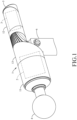
- an embodiment of a hand tool for reducing hand vibration for reducing hand vibration includes a casing 1, a driving module 2, a power module 3, a workpiece 4, a control module 5, and a handle 6.
- the casing 1 includes a front section 11, a rear section 12, and a buffering section 13 connected to the front and rear sections 11, 12.
- the front and rear sections 11, 12 are hollow structures.
- the driving module 2 is disposed on the front section 11.
- the power module 3 is disposed on the rear section 12, and is electrically connected to the driving module 2 for supplying electricity to the driving module 2.
- the rear section 12 is able to be gripped.
- the buffering section 13 has a main body 131 and a protective member 132.
- the main body 131 is made of an elastic material, such as silicone rubber.
- the main body 131 has a large diameter portion 131a connected to the front section 11, a small diameter portion 131b extending from the large diameter portion 131a and connected to the rear section 12, a communication channel 131c running through the large diameter portion 131a and the small diameter portion 131b, and an installation slot 131d formed in the large diameter portion 131a and adjacent to the front section 11.
- the small diameter portion 131b has a cross-sectional area that is smaller than that of the large diameter portion 131a, and is eccentric with respect to the large diameter portion 131a.
- the main body 131 further has a handle connecting portion 131e connecting the large diameter portion 131a and the small diameter portion 131b for connecting the handle 6.
- the user can hold the rear section 12 and move the workpiece 4 to contact a body part which requires massage. Vibration generated during the massage process (i.e., during operation of the workpiece 4) can be absorbed by the buffering section 13 to reduce the vibration transmitted to the rear section 12, thereby reducing the vibration passed on to the hand gripping the rear section 12 and reducing the risk of hand injury caused by vibration.
- FIG. 7 shows an extended state of the telescopic section 62 relative to the fixed section 61 in which the length of the handle 6 is relatively long.
- Fig. 8 shows a retracted state of the telescopic section 62 relative to the fixed section 61 in which the length of the handle 6 is relatively shoort.
- the angle between the handle 6 and the buffering section 13 is adjustable. The user can pivot the handle 6 relative to the buffering section 13 as needed, which allows easy application of force to abut the workpiece 4 against the location requiring massage when the user is gripping the handle 6. Simultaneously, vibration generated during operation of the workpiece 4 can be absorbed by the buffering section 13 to reduce vibration transmitted to the handle 6, thereby reducing the vibration of the hand gripping the handle 6 and reducing the risk of injury of the hand caused by vibration.
- the hand tool further includes an expansion module 7.
- the expansion module 7 includes an extension member 71 and a cover 72.
- the extension member 71 includes a barrel body 711, a chargeable and dischargeable battery 712 disposed in the barrel body 711, two electrical connectors 713 exposed from the barrel body 711 and electrically connected to the battery 712, a light emitting element 714 disposed on one end of the barrel body 711, a switch button 715, a buckling portion 716 and an unlock button 717.
- the light emitting element 714 is electrically connected to the battery 712 such that the extension member 71 may be used as a flashlight.
- the switch button 715 is electrically connected to the light emitting element 714 to turn the light emitting element 714 on or off.
- the electrical connectors 713 are different types of connectors, one of which is a Type A USB connector 52, where the other is a Type C USB connector 52.
- the electrical connectors 713 are available for connection with different types of USB plugs to either charge the battery 712, or use the battery 712 as a mobile power source.
- the cover 72 covers the barrel body 711 at one end opposite to the light emitting element 714. Referring to Figs. 12 to 14 , in this embodiment, the telescopic section 62 of the handle 6 has a connecting hole 621 at a distal end thereof.
- the extension member 71 is removably connected to the handle 6 so as to extend the length of the handle 6.
- the cover 72 is removed first, then the buckling portion 716 and the connecting hole 621 are engaged with each other.
- the unlock button 717 is pressed to disengage the buckling portion 716 from the connecting hole 621 so as to separate the extension member 71 from the handle 6.
- the expansion module 7 can be used multi-functionally.
- the vibration generated during operation of the workpiece 4 can be absorbed by the buffering section 13, so that the vibration on the hand gripping the hand tool can be reduced in order to reduce the risk of the hand being injured.
- the terms “attached”, “connected”, “fixed”, etc. should be understood in a broad sense, and may be fixed connection, detachable connection, or be integral; may be mechanical connections or electrical connections; may be directly connected, or may also be indirectly connected through a middle medium, may be the internal connection between two elements or interaction relationship of the two elements.
- a person skilled in the art may appreciate the specific meaning of the foregoing terms in this disclosure.
- the specific features, structures, etc. described in the embodiments are included in at least one embodiment, such as those skilled in the art may combine features of different implementations without conflicting with each other.
Landscapes
- Health & Medical Sciences (AREA)
- Rehabilitation Therapy (AREA)
- Animal Behavior & Ethology (AREA)
- Epidemiology (AREA)
- Pain & Pain Management (AREA)
- Physical Education & Sports Medicine (AREA)
- Veterinary Medicine (AREA)
- Life Sciences & Earth Sciences (AREA)
- Public Health (AREA)
- General Health & Medical Sciences (AREA)
- Mechanical Engineering (AREA)
- Engineering & Computer Science (AREA)
- Percussion Or Vibration Massage (AREA)
- Manipulator (AREA)
- Percussive Tools And Related Accessories (AREA)
Claims (6)
- Handwerkzeug zum Reduzieren von Handvibrationen, umfassend:ein Gehäuse (1), das ein vorderes Stück (11), ein hinteres Stück (12) und ein Pufferstück (13), das zwischen dem genannten vorderen und hinteren Stück (11, 12) verbunden ist, einschließt, wobei das genannte Pufferstück (13) aus einem elastischen Material gefertigt ist, wobei das genannte hintere Stück (12) zum Greifen angepasst ist;ein auf dem genannten vorderen Stück (11) angeordnetes Antriebsmodul (2);ein auf dem genannten hinteren Stück (12) angeordnetes und mit dem genannten Antriebsmodul (2) elektrisch verbundenes Strommodul (3) zum Liefern von Elektrizität an das genannte Antriebsmodul (2); undein mit dem genannten Antriebsmodul (2) verbundenes Arbeitsgerät (4), das sich von dem genannten vorderen Stück (11) heraus erstreckt und von dem genannten Antriebsmotor (2) angetrieben wird, um betrieben zu werden;wobei das genannte Handwerkzeug dadurch gekennzeichnet ist, dass:
das genannte Pufferstück (13) einen Hauptkörper (131) und ein Schutzglied (132) einschließt;wobei der genannte Hauptkörper (131) Folgendes aufweist: einen großen Durchmesserabschnitt (131a), der mit dem genannten vorderen Stück (11) verbunden ist, einen kleinen Durchmesserabschnitt (131b), der sich aus dem genannten großen Durchmesserabschnitt (131a) erstreckt und mit dem genannten hinteren Abschnitt (12) verbunden ist, einen Kommunikationskanal (131c), der sich durch den genannten großen Durchmesserabschnitt (131a) und den genannten kleinen Durchmesserabschnitt (131b) erstreckt, und einen Installationsschlitz (131d), der in dem genannten großen Durchmesserabschnitt (131a) und an das genannte vordere Stück (11) angrenzend gebildet ist; undwobei genannte Schutzglied (132) Folgendes einschließt: einen Tellerkörperabschnitt (132a), der in dem genannten Installationsschlitz (131d) installiert ist, und einen Rohrkörperabschnitt (132b), der sich aus dem genannten Tellerkörperabschnitt (132a) erstreckt und in den genannten Kommunikationskanal (131c) erstreckt, wobei der genannte Tellerkörperabschnitt (132a) und der genannte Rohrkörperabschnitt (132b) zusammenwirkend einen Drahtkanal (132c) definieren. - Handwerkzeug zum Reduzieren von Handvibrationen nach Anspruch 1, das einen Griff (6) umfasst, der mit dem genannten Pufferstück (13) verbunden ist.
- Handwerkzeug zum Reduzieren von Handvibrationen nach Anspruch 2, wobei der genannte Griff (6) und das genannte Pufferstück (13) entfernbar miteinander verbunden sind.
- Handwerkzeug zum Reduzieren von Handvibrationen nach Anspruch 2, wobei der genannte Griff (6) und das genannte Pufferstück (13) schwenkbar verbunden sind, sodass der Winkel zwischen dem genannten Griff (6) und dem genannten Pufferstück (13) verstellbar ist.
- Handwerkzeug zum Reduzieren von Handvibrationen nach Anspruch 1, wobei ferner ein an einem Ende des genannten hinteren Stücks (12) angeordnetes Steuerungsmodul (5), das mit dem genannten Antriebsmodul (2) und dem genannten Strommodul (3) elektrisch verbunden ist, und eine Steuerungstaste (51) einschließt, die drückbar ist.
- Handwerkzeug zum Reduzieren von Handvibrationen nach Anspruch 1, wobei das genannte Arbeitsgerät (4) ein Massagekopf ist.
Applications Claiming Priority (1)
| Application Number | Priority Date | Filing Date | Title |
|---|---|---|---|
| TW110145795A TWI800142B (zh) | 2021-12-08 | 2021-12-08 | 減少手部被震動的手工具 |
Publications (4)
| Publication Number | Publication Date |
|---|---|
| EP4194150A2 EP4194150A2 (de) | 2023-06-14 |
| EP4194150A3 EP4194150A3 (de) | 2023-08-23 |
| EP4194150C0 EP4194150C0 (de) | 2025-06-25 |
| EP4194150B1 true EP4194150B1 (de) | 2025-06-25 |
Family
ID=84330524
Family Applications (1)
| Application Number | Title | Priority Date | Filing Date |
|---|---|---|---|
| EP22206039.4A Active EP4194150B1 (de) | 2021-12-08 | 2022-11-08 | Handwerkzeug zur reduzierung von handschwingungen |
Country Status (3)
| Country | Link |
|---|---|
| US (1) | US20230172798A1 (de) |
| EP (1) | EP4194150B1 (de) |
| TW (1) | TWI800142B (de) |
Families Citing this family (1)
| Publication number | Priority date | Publication date | Assignee | Title |
|---|---|---|---|---|
| USD1002024S1 (en) * | 2022-01-15 | 2023-10-17 | Shenzhen Shibacm Technology Co., Ltd. | Electric vibrating masturbation device |
Family Cites Families (17)
| Publication number | Priority date | Publication date | Assignee | Title |
|---|---|---|---|---|
| DE102005000205A1 (de) * | 2005-12-23 | 2007-06-28 | Hilti Ag | Handgriff eines handgeführten Werkzeuggerätes |
| DE102009022088A1 (de) * | 2009-05-20 | 2010-11-25 | Friedrich Duss Maschinenfabrik Gmbh & Co.Kg | Elektrowerkzeugmaschine, insbesondere handgeführter Bohrhammer |
| US10016337B2 (en) * | 2013-10-28 | 2018-07-10 | PSOAS Massage Therapy Offices, P.C. | Device and method for trigger point massage therapy |
| US10513005B2 (en) * | 2016-11-02 | 2019-12-24 | Makita Corporation | Power tool |
| CN210932661U (zh) * | 2019-08-21 | 2020-07-07 | 江苏铁锚工具有限公司 | 一种具有减震功能的筋膜枪 |
| WO2021051672A1 (zh) * | 2019-09-17 | 2021-03-25 | 深圳市非兔健康科技有限公司 | 具有智能调节击打功能的筋膜枪 |
| US20210161759A1 (en) * | 2019-12-03 | 2021-06-03 | Fitness Evolution 808 LLC | Extension arm attachment for a massager apparatus |
| TWI722819B (zh) * | 2020-03-06 | 2021-03-21 | 蘇建忠 | 具拍痰功能之拍背機 |
| CN111888227A (zh) * | 2020-08-13 | 2020-11-06 | 深圳市中航佳智能科技有限公司 | 筋膜枪 |
| CN213490394U (zh) * | 2020-11-07 | 2021-06-22 | 左点实业(湖北)有限公司 | 一种具有减震功能的筋膜枪 |
| CN213851952U (zh) * | 2020-11-10 | 2021-08-03 | 黄可余 | 一种折叠筋膜枪 |
| CN112245262A (zh) * | 2020-11-18 | 2021-01-22 | 东莞市轻活科技有限公司 | 一种按摩枪活塞头的抗磨损结构 |
| CN112545863A (zh) * | 2020-11-20 | 2021-03-26 | 未来穿戴技术有限公司 | 筋膜枪 |
| US12357530B2 (en) * | 2021-05-05 | 2025-07-15 | Charles M. Curley | Self-conforming massage gun and method |
| CN215385797U (zh) * | 2021-06-29 | 2022-01-04 | 深圳市倍轻松科技股份有限公司 | 往复式肌肉放松设备 |
| CN216877115U (zh) * | 2021-12-03 | 2022-07-05 | 杨舒雯 | 可手持使用和固定使用的按摩枪 |
| TWM627659U (zh) * | 2021-12-08 | 2022-06-01 | 黃晨軒 | 減少手部被震動的手工具 |
-
2021
- 2021-12-08 TW TW110145795A patent/TWI800142B/zh active
-
2022
- 2022-11-07 US US17/982,411 patent/US20230172798A1/en active Pending
- 2022-11-08 EP EP22206039.4A patent/EP4194150B1/de active Active
Also Published As
| Publication number | Publication date |
|---|---|
| TWI800142B (zh) | 2023-04-21 |
| EP4194150A3 (de) | 2023-08-23 |
| EP4194150A2 (de) | 2023-06-14 |
| TW202322778A (zh) | 2023-06-16 |
| US20230172798A1 (en) | 2023-06-08 |
| EP4194150C0 (de) | 2025-06-25 |
Similar Documents
| Publication | Publication Date | Title |
|---|---|---|
| US10464228B2 (en) | Lighted shaving apparatus | |
| JP2714462B2 (ja) | 振動式かみそり | |
| EP1690649B1 (de) | Kraftwerkzeug | |
| US20130020106A1 (en) | Power tool | |
| EP4194150B1 (de) | Handwerkzeug zur reduzierung von handschwingungen | |
| EP2080594B1 (de) | Werkzeugmaschine und Schutzvorrichtung für Werkzeugmaschine | |
| DE602008006418D1 (de) | Tragbares körperpflegegerät | |
| CN106181904A (zh) | 背负式工具系统 | |
| JP2012139763A (ja) | 動力工具 | |
| EP2703134B1 (de) | Elektrische haarschneidemaschine | |
| CN108430706A (zh) | 手持式工具机 | |
| EP2639015A2 (de) | Elektrisches Werkzeug | |
| JP2019098464A (ja) | 電動工具 | |
| GB2432036A (en) | Power Tool | |
| EP3689293B1 (de) | Pflegeeinheit | |
| US20070289147A1 (en) | Battery-0perated pruning device | |
| CN108666476A (zh) | 电池包组件、电动工具、装配结构、汽油机及园林工具 | |
| CN1636682A (zh) | 电动手持式工具机 | |
| KR20120116233A (ko) | 충전식 배터리를 가지는 전동공구 | |
| CN213226044U (zh) | 附件工具收纳装置及园林工具 | |
| TWM627659U (zh) | 減少手部被震動的手工具 | |
| JP2019098466A (ja) | 電動工具 | |
| CN219803940U (zh) | 颈部按摩仪 | |
| CN201735886U (zh) | 手持式工具 | |
| CN215968579U (zh) | 电动工具以及用于电动工具的壳体 |
Legal Events
| Date | Code | Title | Description |
|---|---|---|---|
| PUAI | Public reference made under article 153(3) epc to a published international application that has entered the european phase |
Free format text: ORIGINAL CODE: 0009012 |
|
| STAA | Information on the status of an ep patent application or granted ep patent |
Free format text: STATUS: THE APPLICATION HAS BEEN PUBLISHED |
|
| AK | Designated contracting states |
Kind code of ref document: A2 Designated state(s): AL AT BE BG CH CY CZ DE DK EE ES FI FR GB GR HR HU IE IS IT LI LT LU LV MC ME MK MT NL NO PL PT RO RS SE SI SK SM TR |
|
| PUAL | Search report despatched |
Free format text: ORIGINAL CODE: 0009013 |
|
| AK | Designated contracting states |
Kind code of ref document: A3 Designated state(s): AL AT BE BG CH CY CZ DE DK EE ES FI FR GB GR HR HU IE IS IT LI LT LU LV MC ME MK MT NL NO PL PT RO RS SE SI SK SM TR |
|
| RIC1 | Information provided on ipc code assigned before grant |
Ipc: A61H 23/00 20060101ALI20230719BHEP Ipc: B25F 5/00 20060101AFI20230719BHEP |
|
| STAA | Information on the status of an ep patent application or granted ep patent |
Free format text: STATUS: REQUEST FOR EXAMINATION WAS MADE |
|
| 17P | Request for examination filed |
Effective date: 20230929 |
|
| RBV | Designated contracting states (corrected) |
Designated state(s): AL AT BE BG CH CY CZ DE DK EE ES FI FR GB GR HR HU IE IS IT LI LT LU LV MC ME MK MT NL NO PL PT RO RS SE SI SK SM TR |
|
| GRAP | Despatch of communication of intention to grant a patent |
Free format text: ORIGINAL CODE: EPIDOSNIGR1 |
|
| STAA | Information on the status of an ep patent application or granted ep patent |
Free format text: STATUS: GRANT OF PATENT IS INTENDED |
|
| INTG | Intention to grant announced |
Effective date: 20250117 |
|
| GRAS | Grant fee paid |
Free format text: ORIGINAL CODE: EPIDOSNIGR3 |
|
| GRAA | (expected) grant |
Free format text: ORIGINAL CODE: 0009210 |
|
| STAA | Information on the status of an ep patent application or granted ep patent |
Free format text: STATUS: THE PATENT HAS BEEN GRANTED |
|
| AK | Designated contracting states |
Kind code of ref document: B1 Designated state(s): AL AT BE BG CH CY CZ DE DK EE ES FI FR GB GR HR HU IE IS IT LI LT LU LV MC ME MK MT NL NO PL PT RO RS SE SI SK SM TR |
|
| REG | Reference to a national code |
Ref country code: GB Ref legal event code: FG4D |
|
| REG | Reference to a national code |
Ref country code: CH Ref legal event code: EP |
|
| REG | Reference to a national code |
Ref country code: CH Ref legal event code: EP |
|
| REG | Reference to a national code |
Ref country code: IE Ref legal event code: FG4D |
|
| REG | Reference to a national code |
Ref country code: DE Ref legal event code: R096 Ref document number: 602022016387 Country of ref document: DE |
|
| U01 | Request for unitary effect filed |
Effective date: 20250715 |
|
| U07 | Unitary effect registered |
Designated state(s): AT BE BG DE DK EE FI FR IT LT LU LV MT NL PT RO SE SI Effective date: 20250721 |
|
| PG25 | Lapsed in a contracting state [announced via postgrant information from national office to epo] |
Ref country code: NO Free format text: LAPSE BECAUSE OF FAILURE TO SUBMIT A TRANSLATION OF THE DESCRIPTION OR TO PAY THE FEE WITHIN THE PRESCRIBED TIME-LIMIT Effective date: 20250925 Ref country code: GR Free format text: LAPSE BECAUSE OF FAILURE TO SUBMIT A TRANSLATION OF THE DESCRIPTION OR TO PAY THE FEE WITHIN THE PRESCRIBED TIME-LIMIT Effective date: 20250926 |
|
| PG25 | Lapsed in a contracting state [announced via postgrant information from national office to epo] |
Ref country code: HR Free format text: LAPSE BECAUSE OF FAILURE TO SUBMIT A TRANSLATION OF THE DESCRIPTION OR TO PAY THE FEE WITHIN THE PRESCRIBED TIME-LIMIT Effective date: 20250625 |
|
| PG25 | Lapsed in a contracting state [announced via postgrant information from national office to epo] |
Ref country code: RS Free format text: LAPSE BECAUSE OF FAILURE TO SUBMIT A TRANSLATION OF THE DESCRIPTION OR TO PAY THE FEE WITHIN THE PRESCRIBED TIME-LIMIT Effective date: 20250925 |
|
| REG | Reference to a national code |
Ref country code: CH Ref legal event code: U11 Free format text: ST27 STATUS EVENT CODE: U-0-0-U10-U11 (AS PROVIDED BY THE NATIONAL OFFICE) Effective date: 20251201 |
|
| U20 | Renewal fee for the european patent with unitary effect paid |
Year of fee payment: 4 Effective date: 20251030 |
|
| PG25 | Lapsed in a contracting state [announced via postgrant information from national office to epo] |
Ref country code: IS Free format text: LAPSE BECAUSE OF FAILURE TO SUBMIT A TRANSLATION OF THE DESCRIPTION OR TO PAY THE FEE WITHIN THE PRESCRIBED TIME-LIMIT Effective date: 20251025 |
|
| PG25 | Lapsed in a contracting state [announced via postgrant information from national office to epo] |
Ref country code: SM Free format text: LAPSE BECAUSE OF FAILURE TO SUBMIT A TRANSLATION OF THE DESCRIPTION OR TO PAY THE FEE WITHIN THE PRESCRIBED TIME-LIMIT Effective date: 20250625 |
|
| PGFP | Annual fee paid to national office [announced via postgrant information from national office to epo] |
Ref country code: CH Payment date: 20251201 Year of fee payment: 4 |
|
| PG25 | Lapsed in a contracting state [announced via postgrant information from national office to epo] |
Ref country code: CZ Free format text: LAPSE BECAUSE OF FAILURE TO SUBMIT A TRANSLATION OF THE DESCRIPTION OR TO PAY THE FEE WITHIN THE PRESCRIBED TIME-LIMIT Effective date: 20250625 |
|
| PG25 | Lapsed in a contracting state [announced via postgrant information from national office to epo] |
Ref country code: PL Free format text: LAPSE BECAUSE OF FAILURE TO SUBMIT A TRANSLATION OF THE DESCRIPTION OR TO PAY THE FEE WITHIN THE PRESCRIBED TIME-LIMIT Effective date: 20250625 |
|
| PG25 | Lapsed in a contracting state [announced via postgrant information from national office to epo] |
Ref country code: SK Free format text: LAPSE BECAUSE OF FAILURE TO SUBMIT A TRANSLATION OF THE DESCRIPTION OR TO PAY THE FEE WITHIN THE PRESCRIBED TIME-LIMIT Effective date: 20250625 |
|
| PG25 | Lapsed in a contracting state [announced via postgrant information from national office to epo] |
Ref country code: ES Free format text: LAPSE BECAUSE OF FAILURE TO SUBMIT A TRANSLATION OF THE DESCRIPTION OR TO PAY THE FEE WITHIN THE PRESCRIBED TIME-LIMIT Effective date: 20250625 |