EP4193134B1 - Force sensing device - Google Patents
Force sensing device Download PDFInfo
- Publication number
- EP4193134B1 EP4193134B1 EP21765968.9A EP21765968A EP4193134B1 EP 4193134 B1 EP4193134 B1 EP 4193134B1 EP 21765968 A EP21765968 A EP 21765968A EP 4193134 B1 EP4193134 B1 EP 4193134B1
- Authority
- EP
- European Patent Office
- Prior art keywords
- conductive layer
- force
- sensing device
- pressure sensitive
- force sensing
- Prior art date
- Legal status (The legal status is an assumption and is not a legal conclusion. Google has not performed a legal analysis and makes no representation as to the accuracy of the status listed.)
- Active
Links
Images


Classifications
-
- G—PHYSICS
- G01—MEASURING; TESTING
- G01L—MEASURING FORCE, STRESS, TORQUE, WORK, MECHANICAL POWER, MECHANICAL EFFICIENCY, OR FLUID PRESSURE
- G01L1/00—Measuring force or stress, in general
- G01L1/20—Measuring force or stress, in general by measuring variations in ohmic resistance of solid materials or of electrically-conductive fluids; by making use of electrokinetic cells, i.e. liquid-containing cells wherein an electrical potential is produced or varied upon the application of stress
- G01L1/22—Measuring force or stress, in general by measuring variations in ohmic resistance of solid materials or of electrically-conductive fluids; by making use of electrokinetic cells, i.e. liquid-containing cells wherein an electrical potential is produced or varied upon the application of stress using resistance strain gauges
- G01L1/2287—Measuring force or stress, in general by measuring variations in ohmic resistance of solid materials or of electrically-conductive fluids; by making use of electrokinetic cells, i.e. liquid-containing cells wherein an electrical potential is produced or varied upon the application of stress using resistance strain gauges constructional details of the strain gauges
-
- G—PHYSICS
- G01—MEASURING; TESTING
- G01L—MEASURING FORCE, STRESS, TORQUE, WORK, MECHANICAL POWER, MECHANICAL EFFICIENCY, OR FLUID PRESSURE
- G01L1/00—Measuring force or stress, in general
- G01L1/18—Measuring force or stress, in general using properties of piezo-resistive materials, i.e. materials of which the ohmic resistance varies according to changes in magnitude or direction of force applied to the material
-
- G—PHYSICS
- G01—MEASURING; TESTING
- G01B—MEASURING LENGTH, THICKNESS OR SIMILAR LINEAR DIMENSIONS; MEASURING ANGLES; MEASURING AREAS; MEASURING IRREGULARITIES OF SURFACES OR CONTOURS
- G01B7/00—Measuring arrangements characterised by the use of electric or magnetic techniques
- G01B7/16—Measuring arrangements characterised by the use of electric or magnetic techniques for measuring the deformation in a solid, e.g. by resistance strain gauge
- G01B7/18—Measuring arrangements characterised by the use of electric or magnetic techniques for measuring the deformation in a solid, e.g. by resistance strain gauge using change in resistance
-
- G—PHYSICS
- G01—MEASURING; TESTING
- G01L—MEASURING FORCE, STRESS, TORQUE, WORK, MECHANICAL POWER, MECHANICAL EFFICIENCY, OR FLUID PRESSURE
- G01L1/00—Measuring force or stress, in general
- G01L1/20—Measuring force or stress, in general by measuring variations in ohmic resistance of solid materials or of electrically-conductive fluids; by making use of electrokinetic cells, i.e. liquid-containing cells wherein an electrical potential is produced or varied upon the application of stress
-
- G—PHYSICS
- G01—MEASURING; TESTING
- G01L—MEASURING FORCE, STRESS, TORQUE, WORK, MECHANICAL POWER, MECHANICAL EFFICIENCY, OR FLUID PRESSURE
- G01L1/00—Measuring force or stress, in general
- G01L1/20—Measuring force or stress, in general by measuring variations in ohmic resistance of solid materials or of electrically-conductive fluids; by making use of electrokinetic cells, i.e. liquid-containing cells wherein an electrical potential is produced or varied upon the application of stress
- G01L1/205—Measuring force or stress, in general by measuring variations in ohmic resistance of solid materials or of electrically-conductive fluids; by making use of electrokinetic cells, i.e. liquid-containing cells wherein an electrical potential is produced or varied upon the application of stress using distributed sensing elements
Definitions
- the present invention relates to a force sensing device, a method of manufacturing the force sensing device and a method of testing the force sensing device.
- US 2014/076063 A1 (LISSEMAN JASON [US] ET AL ) describes a sensor comprising a substrate, conductive elements and an electroactive layer.
- the electroactive layer defines an electrical property which is configured to vary in relation to a magnitude of pressure. It is desirable to improve the pressure sensitivity of current force sensing devices by improving the dynamic response.
- CN 109 115 376 A discloses a capacitive flexible pressure sensor comprising a polymer elastomer electrode, an insulating layer film and an ITO electrode.
- the sensor includes a micro structured array comprising micro structured protrusions.
- WO 2019/222969 A1 (SHENZHEN INST ADV TECH [CN]) describes a further flexible pressure sensor based on a hemispheric microstructure aimed at improving the measurement range and sensitivity of the pressure sensor.
- a force sensing device as claimed in claim 1.
- a method of manufacturing a force sensing device as claimed in claim 10.
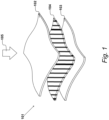
- a force sensing device 101 comprises a first conductive layer 102 and a second conductive layer 103. Force sensing device 101 is further provided with a pressure sensitive active layer 104 which is responsive to a mechanical interaction and is positioned between conductive layer 102 and conductive layer 103. In Figure 1 , force sensing device 101 is shown in a schematic exploded view for illustrative purposes.
- conductive layer 102 and conductive layer 103 each comprise a conductive material.
- the conductive material comprises a metallic material such as silver-based printable ink or a carbon-based material such as a carbon-based printable ink. It is appreciated that, in an embodiment, the metallic materials of the first and second conductive layers may be substantially similar or substantially different.
- Pressure sensitive active layer 104 comprises a pressure sensitive material, and in an embodiment, the pressure sensitive material comprises a quantum tunnelling material. In an embodiment the pressure sensitive material comprises a printable ink. Examples of suitable materials can be obtained from the present applicant, Peratech Holdco Limited, Brompton-on-Swale, United Kingdom.
- Quantum tunnelling materials of this type are responsive to a mechanical interaction in that, when a force is applied, they exhibit a change in electrical resistance which can be used to measure the nature of the force applied. It is appreciated that other pressure sensitive materials may be utilised which also exhibit a change in resistance on application of an applied force.
- the layers of force sensing device 101 are held in close proximity such that, when a mechanical interaction, such as a force or pressure, is applied to, for example, the top surface of conductive layer 102 in the direction of arrow 105, an electric current is transmitted through conductive layer 102 and active layer 104 to conductive layer 103.
- a mechanical interaction such as a force or pressure
- the conductive layers are held apart by the active layer and an electric current is not transmitted.
- the response to the mechanical interaction can be utilised to calculate the magnitude of the mechanical interaction and in some embodiments, the position of the mechanical interaction.
- force sensing device 101 is typically formed as a force sensing device having a substantially circular cross-section when viewed from above.
- force sensing device 101 may comprise an alternative cross-sectional area, such as a substantially square-shaped cross-sectional area.
- Pressure sensitive active layer 104 may comprise a plurality of force sensing elements, thereby enabling the magnitude of an applied force in the direction of arrow 105 to be calculated.
- the dynamic range of force sensitivity of conventional force sensing devices of this type is in part dependent on a smooth increase in contact area between conductive layer 102 and conductive layer 103 with increase in force or pressure applied.
- the present invention aims to adapt these layers compared to conventional force sensing devices so as to optimise the increase in contact area between first and second conductive layers 102 and 103, thereby improving the dynamic range.
- force sensing device 101 further comprises a force distribution structure which is configured to extend an applied force across active layer 104, and expand the contact area between pressure sensitive active layer 104 and conductive layer 102 as will be described in further detail in Figures 2 to 4 .
- Force sensing device 101 comprises conductive layer 102 and conductive layer 103 which are spaced apart by spacer gasket 201. Thus, between conductive layer 102 and conductive layer 103 is air gap 202 which maintains a space between conductive layer 102 and conductive layer 103.
- pressure sensitive active layer 104 Positioned between conductive layer 102 and conductive layer 103 is pressure sensitive active layer 104 and a force distribution structure 203 configured to extend a force applied across pressure sensitive active layer 104.
- Force distribution structure 203 is configured to expand the contact area between pressure sensitive active layer 104 and conductive layer 102 in response to a force, such as force 105, being applied to the force sensing device 101.
- force distribution structure 203 is not only positioned between conductive layer 102 and conductive layer 103, but also extends between a first end 204 and a second end 205 of conductive layer 102 thereby permitting expansion of the force and increasing across the whole of the layer and increasing the contact area between the conductive layer 102 and pressure sensitive active layer 104.
- FIG. 2 shows the force sensing device 101 in an uncompressed state in which a force or pressure has not been applied.
- force distribution structure 203 is retained between the two conductive layers in a rest configuration.
- force distribution structure comprises a substantially dome-shaped cross-section as shown. It is appreciated that alternative cross-sections may be utilised that also allow for an applied force to be extended across pressure sensitive active layer 104. Thus, while a three-dimensional dome-shaped hemispherical cross-section is suitable in this case, alternatively dimensioned hemispherical cross-sections may be utilised along with other suitable shapes.
- force distribution structure 203 is axially symmetrical about a centre axis.
- Force distribution structure 203 also comprises a substantially rigid material.
- pressure sensitive active layer 104 is formed as part of the force distribution structure which comprises a pressure sensitive material applied over a solid three-dimensional structure.
- the pressure sensitive material may be applied to an upper surface of the force distribution structure 203 to form the pressure sensitive active layer 104.
- the pressure sensitive material may be printed over the substantially rigid material of force distribution structure 203.
- force distribution structure 203 itself is comprised of a pressure sensitive material which forms the entire structure.
- the force distribution structure 203 may be considered the pressure sensitive active layer 104 such that the force distribution structure can be considered to provide the pressure sensitive active layer.
- the pressure sensitive material comprises a quantum tunnelling material such as that previously identified as available from the present applicant, Peratech Holdco Limited.
- conductive layer 102 and conductive layer 103 each comprise a conductive ink which is printed onto a substrate.
- the substrate comprises polyethylene terephthalate (PET).
- a first substrate is provided and a conductive ink is printed onto the first substrate to produce conductive layer 102.
- a further substrate is then provided and a conductive ink is printed onto the second substrate to produce conductive layer 103.
- force sensing device 101 may be activated by the application of an elastic actuator 301 to a top surface 302 of conductive layer 102 to provide a mechanical interaction to force sensing device 101.
- This method of testing the force sensing device 101 simulates a pressure or force applied to force sensing device 101 which may take the form of a finger press of a user of a force sensing device or similar in accordance with the present invention.
- Figure 3 therefore shows the elastic actuator 301 positioned for an application of a force for transmission to force sensing device 101 to conductive layer 102, pressure sensitive active layer 104 and conductive layer 103.
- force sensing device is shown in an uncompressed state whereby a force is yet to be applied.
- a distributed force 401 is applied by means of elastic actuator 301 as shown in Figure 4 moving the force sensing device form the uncompressed state of Figure 3 to the compressed state of Figure 4 .
- a force 401 is uniformly applied to upper surface 402 of conductive layer 102.
- This deforms conductive layer 102 which, due to the nature of the force distribution structure 302 is spread across a larger cross-sectional area of conductive layer 102. As indicated, this deforms conductive layer 102, however, the application of force is distributed across conductive layer 102 thereby altering the spread of force.
- Figure 5 illustrates a typical conventional set-up for a method of testing a force sensing device which typically gives a positive dynamic range for a force sensing device as used in real-world applications.
- Figure 5 shows a conventional force sensing device 501 comprising conductive layer 502 and conductive layer 503 which are spaced apart by means of a spacer gasket 504. Spacer gasket 504 separates conductive layers 502 and 503 and creates an air gap 505 therebetween.
- a hemispherical probe is shown to illustrate the effects on a force sensing device without a force distribution structure in which a force is applied 506 by means of hemispherical probe 507.
- force sensing device 501 is shown in a compressed state.
- the deformation of conductive layer 502 brings conductive layer 502 into contact with conductive layer 503 in the manner shown.
- Figure 6 shows a conventional set-up for a method of testing a force sensing device utilising an elastic actuator.
- a flat elastic actuator 601 is utilised to apply distributed force 602.
- the force sensing device 603 comprises a first conductive layer 604 and second conductive layer 605 which are spaced apart by means of a spacer gasket 606. Force sensing device 603 is shown in a compressed state.
- first conductive layer 604 in response to a force 602 from actuator 601, brings conductive layer 604 into contact with conductive layer 605.
- Figure 7 shows an area-force curve illustrating the different dynamic responses of the embodiments shown in Figures 4 , 5 and 6 .
- Curve 701 corresponds to the embodiment and present invention of Figure 4 .
- Curve 702 corresponds to the embodiment shown in Figure 5
- curve 703 corresponds to the embodiment shown in Figure 6 .
- curve 702 which corresponds to the hemispherical probe 507 being used on a force sensing device not comprising a force distribution structure of the present invention.
- the area-force response indicates that the contact area increases proportionally to the input force. In this way, as the probe applies a force, the first and second layers make initial contact which gradually expands outwards with deformation of the probe actuator 507.
- the response of the embodiment of Figure 6 again for a force sensing device without a force distribution structure and using elastic actuator 601, indicates that as the actuator applies force 602 first conductive layer and second conductive layer make full contact immediately with no subsequent increase in contact area for further increase in applied force.
- curve 701 can be produced which indicates a reasonable approximation of the probe response.
- the elastic actuator 301 applies distributed force 401
- the contact expands outwards conforming to force distribution structure 302. Consequently, the area-force dynamic range corresponds to the size of the increase in area for a given increase in force. This will be illustrated further in the corresponding logarithmic area-force curve in Figure 8 .
- a logarithmic (logic) area-force curve is shown in respect of Figure 8 .
- Curve 801 corresponds to the embodiment of Figure 4
- curve 802 corresponds to the embodiment of Figure 5
- curve 803 corresponds to the embodiment of Figure 6 .
- the logarithmic scale illustrates the area-force dynamic range and its relationship to the size of the increase in area for a given increase in force.
- curve 801 shows an increase in contact area 805 and curve 802 shows an increase in contact area 806.
- the force sensing device of the present invention therefore provides a force distribution structure within the force sensing device which simulates the force distribution of conventional structures.
- a dynamic range is achieved unlike in conventional procedures as illustrated by the example in Figure 6 . This ensures a smooth gradual increase of the effective dynamic range thereby allowing for more sensitive readings to be taken and improve the sensitivity range of the force sensing device.
Landscapes
- Physics & Mathematics (AREA)
- General Physics & Mathematics (AREA)
- Force Measurement Appropriate To Specific Purposes (AREA)
Applications Claiming Priority (2)
| Application Number | Priority Date | Filing Date | Title |
|---|---|---|---|
| GBGB2012388.1A GB202012388D0 (en) | 2020-08-10 | 2020-08-10 | Force sensing device |
| PCT/GB2021/000089 WO2022034277A1 (en) | 2020-08-10 | 2021-08-09 | Force sensing device |
Publications (2)
| Publication Number | Publication Date |
|---|---|
| EP4193134A1 EP4193134A1 (en) | 2023-06-14 |
| EP4193134B1 true EP4193134B1 (en) | 2024-05-01 |
Family
ID=72519938
Family Applications (1)
| Application Number | Title | Priority Date | Filing Date |
|---|---|---|---|
| EP21765968.9A Active EP4193134B1 (en) | 2020-08-10 | 2021-08-09 | Force sensing device |
Country Status (7)
| Country | Link |
|---|---|
| US (1) | US20230194366A1 (https=) |
| EP (1) | EP4193134B1 (https=) |
| JP (1) | JP2023541792A (https=) |
| KR (1) | KR20230082013A (https=) |
| CN (1) | CN116324358A (https=) |
| GB (1) | GB202012388D0 (https=) |
| WO (1) | WO2022034277A1 (https=) |
Families Citing this family (2)
| Publication number | Priority date | Publication date | Assignee | Title |
|---|---|---|---|---|
| GB2616660B (en) * | 2022-03-17 | 2024-12-04 | Peratech Ip Ltd | Force sensing device |
| DE102023116506B4 (de) * | 2023-06-22 | 2025-03-27 | Sonovum Gmbh | Kraftsensor |
Citations (3)
| Publication number | Priority date | Publication date | Assignee | Title |
|---|---|---|---|---|
| CN109115376A (zh) * | 2018-09-28 | 2019-01-01 | 清华大学深圳研究生院 | 一种电容式柔性压力传感器及其制备方法 |
| WO2019222969A1 (zh) * | 2018-05-24 | 2019-11-28 | 深圳先进技术研究院 | 一种基于半球形微结构的柔性压力传感器及其制造方法 |
| GB2584088A (en) * | 2019-05-17 | 2020-11-25 | Roli Ltd | Force sensor |
Family Cites Families (25)
| Publication number | Priority date | Publication date | Assignee | Title |
|---|---|---|---|---|
| JP3007513U (ja) * | 1994-08-05 | 1995-02-21 | 富士ポリマテック株式会社 | 圧力センサー |
| US7154481B2 (en) * | 2002-06-25 | 2006-12-26 | 3M Innovative Properties Company | Touch sensor |
| EP1437584A1 (de) * | 2003-01-07 | 2004-07-14 | IEE INTERNATIONAL ELECTRONICS & ENGINEERING S.A. | Drucksensor mit elastischer Sensorschicht, deren Oberfläche mikrostrukturiert ist |
| DE102004026307B4 (de) * | 2004-05-31 | 2016-02-11 | Novineon Healthcare Technology Partners Gmbh | Taktiles Instrument |
| DE102007052008A1 (de) * | 2007-10-26 | 2009-04-30 | Andreas Steinhauser | Single- oder multitouchfähiger Touchscreen oder Touchpad bestehend aus einem Array von Drucksensoren sowie Herstellung solcher Sensoren |
| KR101004941B1 (ko) * | 2008-09-30 | 2010-12-28 | 삼성전기주식회사 | 촉각 센서 |
| TWI420086B (zh) * | 2008-10-15 | 2013-12-21 | Ind Tech Res Inst | 軟性電子壓力感測裝置及其製造方法 |
| EP2824549B1 (en) * | 2012-03-09 | 2019-08-07 | Sony Corporation | Sensor device, input device, and electronic apparatus |
| WO2014043664A1 (en) * | 2012-09-17 | 2014-03-20 | Tk Holdings Inc. | Single layer force sensor |
| KR102081892B1 (ko) * | 2013-09-05 | 2020-02-26 | 삼성전자주식회사 | 압저항(piezo-resistive) 전극을 구비한 저항성 압력 센서 |
| CN105716748B (zh) * | 2014-12-22 | 2020-08-21 | 松下知识产权经营株式会社 | 感压元件 |
| US20170350772A1 (en) * | 2014-12-23 | 2017-12-07 | Haydale Graphene Industries Plc | Piezoresistive Device |
| JP2018018159A (ja) * | 2016-07-25 | 2018-02-01 | アルプス電気株式会社 | 入力装置 |
| US11206878B2 (en) * | 2016-08-16 | 2021-12-28 | Timothy W. Markison | Body impact protection system |
| JP6316371B2 (ja) * | 2016-10-13 | 2018-04-25 | Nissha株式会社 | 圧力センサ |
| JP6325639B1 (ja) * | 2016-11-22 | 2018-05-16 | Nissha株式会社 | 圧力センサ |
| CN108775979A (zh) * | 2018-05-10 | 2018-11-09 | 西安建筑科技大学 | 一种高灵敏度柔性压力传感器及其制备方法 |
| CN208140284U (zh) * | 2018-05-25 | 2018-11-23 | 北京京东方技术开发有限公司 | 一种压力感应器件 |
| GB2575874A (en) * | 2018-07-27 | 2020-01-29 | Nurvv Ltd | A force sensitive resistor |
| US11041772B2 (en) * | 2019-03-25 | 2021-06-22 | Toyota Motor Engineering & Manufacturing North America, Inc. | Sensor diffusion stack materials for pressure sensing gloves and methods incorporating the same |
| GB201904768D0 (en) * | 2019-04-04 | 2019-05-22 | Tech 21 Licensing Ltd | A pressure sensor incorporated into a resiliently deformable thermoplastic polymer |
| KR102183309B1 (ko) * | 2019-05-21 | 2020-11-26 | 성균관대학교산학협력단 | 다타입 압력 센서 |
| GB202012390D0 (en) * | 2020-08-10 | 2020-09-23 | Peratech Holdco Ltd | Force sensing device |
| JP2023183073A (ja) * | 2022-06-15 | 2023-12-27 | 本田技研工業株式会社 | 静電容量センサ |
| US12092536B1 (en) * | 2023-04-14 | 2024-09-17 | The Florida International University Board Of Trustees | Multi-modal pressure sensor |
-
2020
- 2020-08-10 GB GBGB2012388.1A patent/GB202012388D0/en not_active Ceased
-
2021
- 2021-08-09 KR KR1020237008353A patent/KR20230082013A/ko active Pending
- 2021-08-09 JP JP2023509590A patent/JP2023541792A/ja active Pending
- 2021-08-09 EP EP21765968.9A patent/EP4193134B1/en active Active
- 2021-08-09 WO PCT/GB2021/000089 patent/WO2022034277A1/en not_active Ceased
- 2021-08-09 CN CN202180069162.9A patent/CN116324358A/zh active Pending
-
2023
- 2023-02-10 US US18/108,071 patent/US20230194366A1/en active Pending
Patent Citations (4)
| Publication number | Priority date | Publication date | Assignee | Title |
|---|---|---|---|---|
| WO2019222969A1 (zh) * | 2018-05-24 | 2019-11-28 | 深圳先进技术研究院 | 一种基于半球形微结构的柔性压力传感器及其制造方法 |
| CN109115376A (zh) * | 2018-09-28 | 2019-01-01 | 清华大学深圳研究生院 | 一种电容式柔性压力传感器及其制备方法 |
| GB2584088A (en) * | 2019-05-17 | 2020-11-25 | Roli Ltd | Force sensor |
| WO2020234197A1 (en) * | 2019-05-17 | 2020-11-26 | ROLI Limited | Force sensor |
Also Published As
| Publication number | Publication date |
|---|---|
| US20230194366A1 (en) | 2023-06-22 |
| GB202012388D0 (en) | 2020-09-23 |
| JP2023541792A (ja) | 2023-10-04 |
| CN116324358A (zh) | 2023-06-23 |
| KR20230082013A (ko) | 2023-06-08 |
| EP4193134A1 (en) | 2023-06-14 |
| WO2022034277A1 (en) | 2022-02-17 |
Similar Documents
| Publication | Publication Date | Title |
|---|---|---|
| Li et al. | Engineered microstructure derived hierarchical deformation of flexible pressure sensor induces a supersensitive piezoresistive property in broad pressure range | |
| KR102081892B1 (ko) | 압저항(piezo-resistive) 전극을 구비한 저항성 압력 센서 | |
| US7464613B2 (en) | Pressure sensor comprising an elastic sensor layer with a microstructured surface | |
| CN102207415B (zh) | 基于导电橡胶的柔性阵列片式压力传感器及制造方法 | |
| CN109781315B (zh) | 一种触觉传感器 | |
| EP4193134B1 (en) | Force sensing device | |
| Park et al. | Low-hysteresis and low-interference soft tactile sensor using a conductive coated porous elastomer and a structure for interference reduction | |
| SG174496A1 (en) | Sensor | |
| KR101436991B1 (ko) | 미세 액체금속 액적을 이용한 촉각센서 | |
| KR102423014B1 (ko) | 고민감도 압력센서 및 이의 제조방법 | |
| CN108444620A (zh) | 一种同层式的多级阵列压力传感器 | |
| US12078556B2 (en) | Capacitive flexible tactile sensor based on graded inclined micro-cylinder structure | |
| CN115235656A (zh) | 一种高灵敏柔性压阻传感器及其制备方法 | |
| JP6440187B2 (ja) | 触覚センサ及び集積化センサ | |
| CN210400662U (zh) | 一种基于压阻材料的柔性三维触觉传感器 | |
| Zhou et al. | Three-layer-stacked pressure sensor with a liquid metal-embedded elastomer | |
| DK181377B1 (en) | Tactile sensor, matrix of tactile sensors, and methods for producing the same | |
| JPH04320937A (ja) | 方向圧力感知センサー | |
| CN212059194U (zh) | 一种微形变压力传感器及装置 | |
| Choi et al. | Spatially digitized tactile pressure sensors with tunable sensitivity and sensing range | |
| CN113252228B (zh) | 基于柔弹性曲面梁的高灵敏电容式柔性三维力触觉传感器 | |
| JP2024510382A (ja) | 力検知装置 | |
| WO2021170967A1 (en) | Pressure sensor | |
| CN216206640U (zh) | 一种复合柔性传感阵列 | |
| Zhou et al. | High‐Precision Piezoresistive Sensors Based on Femtosecond Laser Preparation of Conductive PDMS Composites With Microarray Structure |
Legal Events
| Date | Code | Title | Description |
|---|---|---|---|
| STAA | Information on the status of an ep patent application or granted ep patent |
Free format text: STATUS: UNKNOWN |
|
| STAA | Information on the status of an ep patent application or granted ep patent |
Free format text: STATUS: THE INTERNATIONAL PUBLICATION HAS BEEN MADE |
|
| PUAI | Public reference made under article 153(3) epc to a published international application that has entered the european phase |
Free format text: ORIGINAL CODE: 0009012 |
|
| STAA | Information on the status of an ep patent application or granted ep patent |
Free format text: STATUS: REQUEST FOR EXAMINATION WAS MADE |
|
| 17P | Request for examination filed |
Effective date: 20230223 |
|
| AK | Designated contracting states |
Kind code of ref document: A1 Designated state(s): AL AT BE BG CH CY CZ DE DK EE ES FI FR GB GR HR HU IE IS IT LI LT LU LV MC MK MT NL NO PL PT RO RS SE SI SK SM TR |
|
| DAV | Request for validation of the european patent (deleted) | ||
| DAX | Request for extension of the european patent (deleted) | ||
| GRAP | Despatch of communication of intention to grant a patent |
Free format text: ORIGINAL CODE: EPIDOSNIGR1 |
|
| STAA | Information on the status of an ep patent application or granted ep patent |
Free format text: STATUS: GRANT OF PATENT IS INTENDED |
|
| INTG | Intention to grant announced |
Effective date: 20231208 |
|
| RAP3 | Party data changed (applicant data changed or rights of an application transferred) |
Owner name: PERATECH HOLDCO LTD |
|
| GRAS | Grant fee paid |
Free format text: ORIGINAL CODE: EPIDOSNIGR3 |
|
| GRAA | (expected) grant |
Free format text: ORIGINAL CODE: 0009210 |
|
| STAA | Information on the status of an ep patent application or granted ep patent |
Free format text: STATUS: THE PATENT HAS BEEN GRANTED |
|
| AK | Designated contracting states |
Kind code of ref document: B1 Designated state(s): AL AT BE BG CH CY CZ DE DK EE ES FI FR GB GR HR HU IE IS IT LI LT LU LV MC MK MT NL NO PL PT RO RS SE SI SK SM TR |
|
| REG | Reference to a national code |
Ref country code: GB Ref legal event code: FG4D |
|
| REG | Reference to a national code |
Ref country code: CH Ref legal event code: EP |
|
| REG | Reference to a national code |
Ref country code: DE Ref legal event code: R096 Ref document number: 602021012816 Country of ref document: DE |
|
| REG | Reference to a national code |
Ref country code: IE Ref legal event code: FG4D |
|
| REG | Reference to a national code |
Ref country code: LT Ref legal event code: MG9D |
|
| REG | Reference to a national code |
Ref country code: NL Ref legal event code: MP Effective date: 20240501 |
|
| REG | Reference to a national code |
Ref country code: GB Ref legal event code: 732E Free format text: REGISTERED BETWEEN 20240815 AND 20240821 |
|
| REG | Reference to a national code |
Ref country code: GB Ref legal event code: 732E Free format text: REGISTERED BETWEEN 20240822 AND 20240828 |
|
| PG25 | Lapsed in a contracting state [announced via postgrant information from national office to epo] |
Ref country code: IS Free format text: LAPSE BECAUSE OF FAILURE TO SUBMIT A TRANSLATION OF THE DESCRIPTION OR TO PAY THE FEE WITHIN THE PRESCRIBED TIME-LIMIT Effective date: 20240901 |
|
| PG25 | Lapsed in a contracting state [announced via postgrant information from national office to epo] |
Ref country code: BG Free format text: LAPSE BECAUSE OF FAILURE TO SUBMIT A TRANSLATION OF THE DESCRIPTION OR TO PAY THE FEE WITHIN THE PRESCRIBED TIME-LIMIT Effective date: 20240501 |
|
| PG25 | Lapsed in a contracting state [announced via postgrant information from national office to epo] |
Ref country code: HR Free format text: LAPSE BECAUSE OF FAILURE TO SUBMIT A TRANSLATION OF THE DESCRIPTION OR TO PAY THE FEE WITHIN THE PRESCRIBED TIME-LIMIT Effective date: 20240501 Ref country code: FI Free format text: LAPSE BECAUSE OF FAILURE TO SUBMIT A TRANSLATION OF THE DESCRIPTION OR TO PAY THE FEE WITHIN THE PRESCRIBED TIME-LIMIT Effective date: 20240501 |
|
| PGFP | Annual fee paid to national office [announced via postgrant information from national office to epo] |
Ref country code: DE Payment date: 20240731 Year of fee payment: 4 |
|
| PG25 | Lapsed in a contracting state [announced via postgrant information from national office to epo] |
Ref country code: GR Free format text: LAPSE BECAUSE OF FAILURE TO SUBMIT A TRANSLATION OF THE DESCRIPTION OR TO PAY THE FEE WITHIN THE PRESCRIBED TIME-LIMIT Effective date: 20240802 |
|
| PG25 | Lapsed in a contracting state [announced via postgrant information from national office to epo] |
Ref country code: PT Free format text: LAPSE BECAUSE OF FAILURE TO SUBMIT A TRANSLATION OF THE DESCRIPTION OR TO PAY THE FEE WITHIN THE PRESCRIBED TIME-LIMIT Effective date: 20240902 |
|
| REG | Reference to a national code |
Ref country code: AT Ref legal event code: MK05 Ref document number: 1682942 Country of ref document: AT Kind code of ref document: T Effective date: 20240501 |
|
| RAP2 | Party data changed (patent owner data changed or rights of a patent transferred) |
Owner name: PERATECH IP LTD |
|
| PG25 | Lapsed in a contracting state [announced via postgrant information from national office to epo] |
Ref country code: NL Free format text: LAPSE BECAUSE OF FAILURE TO SUBMIT A TRANSLATION OF THE DESCRIPTION OR TO PAY THE FEE WITHIN THE PRESCRIBED TIME-LIMIT Effective date: 20240501 |
|
| PG25 | Lapsed in a contracting state [announced via postgrant information from national office to epo] |
Ref country code: ES Free format text: LAPSE BECAUSE OF FAILURE TO SUBMIT A TRANSLATION OF THE DESCRIPTION OR TO PAY THE FEE WITHIN THE PRESCRIBED TIME-LIMIT Effective date: 20240501 |
|
| PG25 | Lapsed in a contracting state [announced via postgrant information from national office to epo] |
Ref country code: AT Free format text: LAPSE BECAUSE OF FAILURE TO SUBMIT A TRANSLATION OF THE DESCRIPTION OR TO PAY THE FEE WITHIN THE PRESCRIBED TIME-LIMIT Effective date: 20240501 |
|
| PG25 | Lapsed in a contracting state [announced via postgrant information from national office to epo] |
Ref country code: PL Free format text: LAPSE BECAUSE OF FAILURE TO SUBMIT A TRANSLATION OF THE DESCRIPTION OR TO PAY THE FEE WITHIN THE PRESCRIBED TIME-LIMIT Effective date: 20240501 |
|
| REG | Reference to a national code |
Ref country code: DE Ref legal event code: R088 Ref document number: 602021012816 Country of ref document: DE |
|
| PG25 | Lapsed in a contracting state [announced via postgrant information from national office to epo] |
Ref country code: LV Free format text: LAPSE BECAUSE OF FAILURE TO SUBMIT A TRANSLATION OF THE DESCRIPTION OR TO PAY THE FEE WITHIN THE PRESCRIBED TIME-LIMIT Effective date: 20240501 |
|
| PG25 | Lapsed in a contracting state [announced via postgrant information from national office to epo] |
Ref country code: PT Free format text: LAPSE BECAUSE OF FAILURE TO SUBMIT A TRANSLATION OF THE DESCRIPTION OR TO PAY THE FEE WITHIN THE PRESCRIBED TIME-LIMIT Effective date: 20240902 Ref country code: PL Free format text: LAPSE BECAUSE OF FAILURE TO SUBMIT A TRANSLATION OF THE DESCRIPTION OR TO PAY THE FEE WITHIN THE PRESCRIBED TIME-LIMIT Effective date: 20240501 Ref country code: NO Free format text: LAPSE BECAUSE OF FAILURE TO SUBMIT A TRANSLATION OF THE DESCRIPTION OR TO PAY THE FEE WITHIN THE PRESCRIBED TIME-LIMIT Effective date: 20240801 Ref country code: NL Free format text: LAPSE BECAUSE OF FAILURE TO SUBMIT A TRANSLATION OF THE DESCRIPTION OR TO PAY THE FEE WITHIN THE PRESCRIBED TIME-LIMIT Effective date: 20240501 Ref country code: LV Free format text: LAPSE BECAUSE OF FAILURE TO SUBMIT A TRANSLATION OF THE DESCRIPTION OR TO PAY THE FEE WITHIN THE PRESCRIBED TIME-LIMIT Effective date: 20240501 Ref country code: IS Free format text: LAPSE BECAUSE OF FAILURE TO SUBMIT A TRANSLATION OF THE DESCRIPTION OR TO PAY THE FEE WITHIN THE PRESCRIBED TIME-LIMIT Effective date: 20240901 Ref country code: HR Free format text: LAPSE BECAUSE OF FAILURE TO SUBMIT A TRANSLATION OF THE DESCRIPTION OR TO PAY THE FEE WITHIN THE PRESCRIBED TIME-LIMIT Effective date: 20240501 Ref country code: GR Free format text: LAPSE BECAUSE OF FAILURE TO SUBMIT A TRANSLATION OF THE DESCRIPTION OR TO PAY THE FEE WITHIN THE PRESCRIBED TIME-LIMIT Effective date: 20240802 Ref country code: FI Free format text: LAPSE BECAUSE OF FAILURE TO SUBMIT A TRANSLATION OF THE DESCRIPTION OR TO PAY THE FEE WITHIN THE PRESCRIBED TIME-LIMIT Effective date: 20240501 Ref country code: ES Free format text: LAPSE BECAUSE OF FAILURE TO SUBMIT A TRANSLATION OF THE DESCRIPTION OR TO PAY THE FEE WITHIN THE PRESCRIBED TIME-LIMIT Effective date: 20240501 Ref country code: BG Free format text: LAPSE BECAUSE OF FAILURE TO SUBMIT A TRANSLATION OF THE DESCRIPTION OR TO PAY THE FEE WITHIN THE PRESCRIBED TIME-LIMIT Effective date: 20240501 Ref country code: AT Free format text: LAPSE BECAUSE OF FAILURE TO SUBMIT A TRANSLATION OF THE DESCRIPTION OR TO PAY THE FEE WITHIN THE PRESCRIBED TIME-LIMIT Effective date: 20240501 Ref country code: RS Free format text: LAPSE BECAUSE OF FAILURE TO SUBMIT A TRANSLATION OF THE DESCRIPTION OR TO PAY THE FEE WITHIN THE PRESCRIBED TIME-LIMIT Effective date: 20240801 |
|
| REG | Reference to a national code |
Ref country code: DE Ref legal event code: R081 Ref document number: 602021012816 Country of ref document: DE Owner name: PERATECH IP LIMITED, CATTERICK GARRISON, GB Free format text: FORMER OWNER: PERATECH HOLDCO LTD, CATTERICK GARRISON, NORTH YORKSHIRE, GB |
|
| PG25 | Lapsed in a contracting state [announced via postgrant information from national office to epo] |
Ref country code: DK Free format text: LAPSE BECAUSE OF FAILURE TO SUBMIT A TRANSLATION OF THE DESCRIPTION OR TO PAY THE FEE WITHIN THE PRESCRIBED TIME-LIMIT Effective date: 20240501 |
|
| PG25 | Lapsed in a contracting state [announced via postgrant information from national office to epo] |
Ref country code: EE Free format text: LAPSE BECAUSE OF FAILURE TO SUBMIT A TRANSLATION OF THE DESCRIPTION OR TO PAY THE FEE WITHIN THE PRESCRIBED TIME-LIMIT Effective date: 20240501 |
|
| PG25 | Lapsed in a contracting state [announced via postgrant information from national office to epo] |
Ref country code: CZ Free format text: LAPSE BECAUSE OF FAILURE TO SUBMIT A TRANSLATION OF THE DESCRIPTION OR TO PAY THE FEE WITHIN THE PRESCRIBED TIME-LIMIT Effective date: 20240501 |
|
| PG25 | Lapsed in a contracting state [announced via postgrant information from national office to epo] |
Ref country code: RO Free format text: LAPSE BECAUSE OF FAILURE TO SUBMIT A TRANSLATION OF THE DESCRIPTION OR TO PAY THE FEE WITHIN THE PRESCRIBED TIME-LIMIT Effective date: 20240501 Ref country code: SK Free format text: LAPSE BECAUSE OF FAILURE TO SUBMIT A TRANSLATION OF THE DESCRIPTION OR TO PAY THE FEE WITHIN THE PRESCRIBED TIME-LIMIT Effective date: 20240501 |
|
| PG25 | Lapsed in a contracting state [announced via postgrant information from national office to epo] |
Ref country code: SM Free format text: LAPSE BECAUSE OF FAILURE TO SUBMIT A TRANSLATION OF THE DESCRIPTION OR TO PAY THE FEE WITHIN THE PRESCRIBED TIME-LIMIT Effective date: 20240501 |
|
| PG25 | Lapsed in a contracting state [announced via postgrant information from national office to epo] |
Ref country code: SM Free format text: LAPSE BECAUSE OF FAILURE TO SUBMIT A TRANSLATION OF THE DESCRIPTION OR TO PAY THE FEE WITHIN THE PRESCRIBED TIME-LIMIT Effective date: 20240501 Ref country code: SK Free format text: LAPSE BECAUSE OF FAILURE TO SUBMIT A TRANSLATION OF THE DESCRIPTION OR TO PAY THE FEE WITHIN THE PRESCRIBED TIME-LIMIT Effective date: 20240501 Ref country code: RO Free format text: LAPSE BECAUSE OF FAILURE TO SUBMIT A TRANSLATION OF THE DESCRIPTION OR TO PAY THE FEE WITHIN THE PRESCRIBED TIME-LIMIT Effective date: 20240501 Ref country code: EE Free format text: LAPSE BECAUSE OF FAILURE TO SUBMIT A TRANSLATION OF THE DESCRIPTION OR TO PAY THE FEE WITHIN THE PRESCRIBED TIME-LIMIT Effective date: 20240501 Ref country code: DK Free format text: LAPSE BECAUSE OF FAILURE TO SUBMIT A TRANSLATION OF THE DESCRIPTION OR TO PAY THE FEE WITHIN THE PRESCRIBED TIME-LIMIT Effective date: 20240501 Ref country code: CZ Free format text: LAPSE BECAUSE OF FAILURE TO SUBMIT A TRANSLATION OF THE DESCRIPTION OR TO PAY THE FEE WITHIN THE PRESCRIBED TIME-LIMIT Effective date: 20240501 |
|
| REG | Reference to a national code |
Ref country code: DE Ref legal event code: R097 Ref document number: 602021012816 Country of ref document: DE |
|
| PG25 | Lapsed in a contracting state [announced via postgrant information from national office to epo] |
Ref country code: IT Free format text: LAPSE BECAUSE OF FAILURE TO SUBMIT A TRANSLATION OF THE DESCRIPTION OR TO PAY THE FEE WITHIN THE PRESCRIBED TIME-LIMIT Effective date: 20240501 |
|
| PLBE | No opposition filed within time limit |
Free format text: ORIGINAL CODE: 0009261 |
|
| STAA | Information on the status of an ep patent application or granted ep patent |
Free format text: STATUS: NO OPPOSITION FILED WITHIN TIME LIMIT |
|
| REG | Reference to a national code |
Ref country code: CH Ref legal event code: PL |
|
| 26N | No opposition filed |
Effective date: 20250204 |
|
| PG25 | Lapsed in a contracting state [announced via postgrant information from national office to epo] |
Ref country code: LU Free format text: LAPSE BECAUSE OF NON-PAYMENT OF DUE FEES Effective date: 20240809 |
|
| PG25 | Lapsed in a contracting state [announced via postgrant information from national office to epo] |
Ref country code: SI Free format text: LAPSE BECAUSE OF FAILURE TO SUBMIT A TRANSLATION OF THE DESCRIPTION OR TO PAY THE FEE WITHIN THE PRESCRIBED TIME-LIMIT Effective date: 20240501 Ref country code: CH Free format text: LAPSE BECAUSE OF NON-PAYMENT OF DUE FEES Effective date: 20240831 Ref country code: MC Free format text: LAPSE BECAUSE OF FAILURE TO SUBMIT A TRANSLATION OF THE DESCRIPTION OR TO PAY THE FEE WITHIN THE PRESCRIBED TIME-LIMIT Effective date: 20240501 |
|
| REG | Reference to a national code |
Ref country code: BE Ref legal event code: MM Effective date: 20240831 |
|
| PG25 | Lapsed in a contracting state [announced via postgrant information from national office to epo] |
Ref country code: BE Free format text: LAPSE BECAUSE OF NON-PAYMENT OF DUE FEES Effective date: 20240831 |
|
| PG25 | Lapsed in a contracting state [announced via postgrant information from national office to epo] |
Ref country code: FR Free format text: LAPSE BECAUSE OF NON-PAYMENT OF DUE FEES Effective date: 20240831 |
|
| PG25 | Lapsed in a contracting state [announced via postgrant information from national office to epo] |
Ref country code: IE Free format text: LAPSE BECAUSE OF NON-PAYMENT OF DUE FEES Effective date: 20240809 |
|
| PG25 | Lapsed in a contracting state [announced via postgrant information from national office to epo] |
Ref country code: SE Free format text: LAPSE BECAUSE OF FAILURE TO SUBMIT A TRANSLATION OF THE DESCRIPTION OR TO PAY THE FEE WITHIN THE PRESCRIBED TIME-LIMIT Effective date: 20240501 |
|
| PG25 | Lapsed in a contracting state [announced via postgrant information from national office to epo] |
Ref country code: CY Free format text: LAPSE BECAUSE OF FAILURE TO SUBMIT A TRANSLATION OF THE DESCRIPTION OR TO PAY THE FEE WITHIN THE PRESCRIBED TIME-LIMIT; INVALID AB INITIO Effective date: 20210809 |
|
| REG | Reference to a national code |
Ref country code: DE Ref legal event code: R119 Ref document number: 602021012816 Country of ref document: DE |
|
| PG25 | Lapsed in a contracting state [announced via postgrant information from national office to epo] |
Ref country code: HU Free format text: LAPSE BECAUSE OF FAILURE TO SUBMIT A TRANSLATION OF THE DESCRIPTION OR TO PAY THE FEE WITHIN THE PRESCRIBED TIME-LIMIT; INVALID AB INITIO Effective date: 20210809 |