EP4190482B1 - Resin molded article, method for producing resin molded body, and wet-area equipment. - Google Patents
Resin molded article, method for producing resin molded body, and wet-area equipment. Download PDFInfo
- Publication number
- EP4190482B1 EP4190482B1 EP21850065.0A EP21850065A EP4190482B1 EP 4190482 B1 EP4190482 B1 EP 4190482B1 EP 21850065 A EP21850065 A EP 21850065A EP 4190482 B1 EP4190482 B1 EP 4190482B1
- Authority
- EP
- European Patent Office
- Prior art keywords
- resin molded
- molded body
- projections
- uneven structure
- projection
- Prior art date
- Legal status (The legal status is an assumption and is not a legal conclusion. Google has not performed a legal analysis and makes no representation as to the accuracy of the status listed.)
- Active
Links
Images


Classifications
-
- B—PERFORMING OPERATIONS; TRANSPORTING
- B23—MACHINE TOOLS; METAL-WORKING NOT OTHERWISE PROVIDED FOR
- B23K—SOLDERING OR UNSOLDERING; WELDING; CLADDING OR PLATING BY SOLDERING OR WELDING; CUTTING BY APPLYING HEAT LOCALLY, e.g. FLAME CUTTING; WORKING BY LASER BEAM
- B23K26/00—Working by laser beam, e.g. welding, cutting or boring
- B23K26/36—Removing material
- B23K26/362—Laser etching
- B23K26/364—Laser etching for making a groove or trench, e.g. for scribing a break initiation groove
-
- B—PERFORMING OPERATIONS; TRANSPORTING
- B23—MACHINE TOOLS; METAL-WORKING NOT OTHERWISE PROVIDED FOR
- B23K—SOLDERING OR UNSOLDERING; WELDING; CLADDING OR PLATING BY SOLDERING OR WELDING; CUTTING BY APPLYING HEAT LOCALLY, e.g. FLAME CUTTING; WORKING BY LASER BEAM
- B23K26/00—Working by laser beam, e.g. welding, cutting or boring
- B23K26/02—Positioning or observing the workpiece, e.g. with respect to the point of impact; Aligning, aiming or focusing the laser beam
- B23K26/06—Shaping the laser beam, e.g. by masks or multi-focusing
- B23K26/062—Shaping the laser beam, e.g. by masks or multi-focusing by direct control of the laser beam
- B23K26/0622—Shaping the laser beam, e.g. by masks or multi-focusing by direct control of the laser beam by shaping pulses
- B23K26/0624—Shaping the laser beam, e.g. by masks or multi-focusing by direct control of the laser beam by shaping pulses using ultrashort pulses, i.e. pulses of 1 ns or less
-
- B—PERFORMING OPERATIONS; TRANSPORTING
- B23—MACHINE TOOLS; METAL-WORKING NOT OTHERWISE PROVIDED FOR
- B23K—SOLDERING OR UNSOLDERING; WELDING; CLADDING OR PLATING BY SOLDERING OR WELDING; CUTTING BY APPLYING HEAT LOCALLY, e.g. FLAME CUTTING; WORKING BY LASER BEAM
- B23K26/00—Working by laser beam, e.g. welding, cutting or boring
- B23K26/36—Removing material
- B23K26/40—Removing material taking account of the properties of the material involved
- B23K26/402—Removing material taking account of the properties of the material involved involving non-metallic material, e.g. isolators
-
- B—PERFORMING OPERATIONS; TRANSPORTING
- B29—WORKING OF PLASTICS; WORKING OF SUBSTANCES IN A PLASTIC STATE IN GENERAL
- B29C—SHAPING OR JOINING OF PLASTICS; SHAPING OF MATERIAL IN A PLASTIC STATE, NOT OTHERWISE PROVIDED FOR; AFTER-TREATMENT OF THE SHAPED PRODUCTS, e.g. REPAIRING
- B29C59/00—Surface shaping of articles, e.g. embossing; Apparatus therefor
- B29C59/16—Surface shaping of articles, e.g. embossing; Apparatus therefor by wave energy or particle radiation, e.g. infrared heating
-
- B—PERFORMING OPERATIONS; TRANSPORTING
- B23—MACHINE TOOLS; METAL-WORKING NOT OTHERWISE PROVIDED FOR
- B23K—SOLDERING OR UNSOLDERING; WELDING; CLADDING OR PLATING BY SOLDERING OR WELDING; CUTTING BY APPLYING HEAT LOCALLY, e.g. FLAME CUTTING; WORKING BY LASER BEAM
- B23K2101/00—Articles made by soldering, welding or cutting
- B23K2101/18—Sheet panels
-
- B—PERFORMING OPERATIONS; TRANSPORTING
- B23—MACHINE TOOLS; METAL-WORKING NOT OTHERWISE PROVIDED FOR
- B23K—SOLDERING OR UNSOLDERING; WELDING; CLADDING OR PLATING BY SOLDERING OR WELDING; CUTTING BY APPLYING HEAT LOCALLY, e.g. FLAME CUTTING; WORKING BY LASER BEAM
- B23K2103/00—Materials to be soldered, welded or cut
- B23K2103/30—Organic materials
- B23K2103/42—Plastics other than composite materials
-
- B—PERFORMING OPERATIONS; TRANSPORTING
- B29—WORKING OF PLASTICS; WORKING OF SUBSTANCES IN A PLASTIC STATE IN GENERAL
- B29C—SHAPING OR JOINING OF PLASTICS; SHAPING OF MATERIAL IN A PLASTIC STATE, NOT OTHERWISE PROVIDED FOR; AFTER-TREATMENT OF THE SHAPED PRODUCTS, e.g. REPAIRING
- B29C59/00—Surface shaping of articles, e.g. embossing; Apparatus therefor
- B29C59/02—Surface shaping of articles, e.g. embossing; Apparatus therefor by mechanical means, e.g. pressing
- B29C59/022—Surface shaping of articles, e.g. embossing; Apparatus therefor by mechanical means, e.g. pressing characterised by the disposition or the configuration, e.g. dimensions, of the embossments or the shaping tools therefor
- B29C2059/023—Microembossing
-
- B—PERFORMING OPERATIONS; TRANSPORTING
- B29—WORKING OF PLASTICS; WORKING OF SUBSTANCES IN A PLASTIC STATE IN GENERAL
- B29K—INDEXING SCHEME ASSOCIATED WITH SUBCLASSES B29B, B29C OR B29D, RELATING TO MOULDING MATERIALS OR TO MATERIALS FOR MOULDS, REINFORCEMENTS, FILLERS OR PREFORMED PARTS, e.g. INSERTS
- B29K2995/00—Properties of moulding materials, reinforcements, fillers, preformed parts or moulds
- B29K2995/0037—Other properties
- B29K2995/0093—Other properties hydrophobic
Definitions
- the present invention relates to a resin molded body, a method for producing the resin molded body, and wet-area equipment.
- a resin molded body that exhibits liquid repellency by having a plurality of rib projections formed on its surface, and having a fluorine coating applied to a distal end surface of each of the rib projections is known.
- Each of the rib projections includes a wider distal end portion than a base end portion (see JP 2019 188605 A , for example).
- WO 2015/021192 A1 describes a medical device, which includes a portion made from a base material having a surface adapted for contact with biological material, and wherein the surface is modified to become superhydrophobic, superoleophobic, or both, using only the base material, excluding non-material coatings.
- the surface may be modified using a subtractive process, an additive process, or a combination thereof.
- the product of the process may form part of an implantable device or a medical instrument, including a medical device or instrument associated with an intraocular procedure.
- the surface may be modified to include micrometer- or nanometer-sized pillars, posts, pits or cavitations; hierarchical structures having asperities; or posts/pillars with caps having dimensions greater than the diameters of the posts or pillars.
- liquid repellency of the resin molded body deteriorates due to deterioration of the fluorine coat. Furthermore, there is a risk that small droplets could enter between the rib projections, resulting in deterioration of liquid repellency.
- an object of the present invention is to provide a resin molded body and the like having high liquid repellency.
- the present invention relates to a resin molded body according to claim 1, a method according to claim 5, and a wet-area equipment according to claim 7.
- Claims 2 to 4 refer to specifically advantageous realizations of the resin molded body according to claim 1.
- Claim 6 refers to a specifically advantageous realization of the method according to claim 5.
- a resin molded body according to an aspect of the present invention includes the features recited in claim 1.
- a method for producing the resin molded body according to an aspect of the present invention is a method for producing the resin molded body that includes forming the uneven structure surface by performing laser processing on a surface of a resin base material.
- Wet-area equipment includes the above-described resin molded body.
- the present invention can provide a resin molded body and the like having high liquid repellency.
- Embodiments 1 and 2 as described below are not encompassed by the wording of the claims but are considered as useful for understanding the invention.
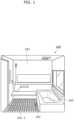
- FIG. 1 is a perspective view illustrating bathroom 100 in which resin molded body 1 according to Embodiment 1 is used.
- bathroom 100 is an example of wet-area equipment and includes floor 101 including drain outlet 102, wall 103, and bathtub 104. Although it is sufficient that at least one of floor 101, wall 103, or bathtub 104 is formed using resin molded body 1, the present embodiment describes, as an example, a case where floor 101 is formed using resin molded body 1.
- FIG. 2 is a plan view illustrating an enlarged view of a surface structure of floor 101 according to Embodiment 1.
- FIG. 3 is a cross-sectional view taken along line III-III in FIG. 2 .
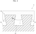
- a surface of resin molded body 1 is uneven structure surface 30 that has a so-called reentrant structure.
- Uneven structure surface 30 exhibits liquid repellency by having a plurality of projections 31 and a plurality of recesses 32 alternately arranged in a predetermined direction in a planar form.
- uneven structure surface 30 includes the plurality of projections 31 arranged in a matrix in a plan view.
- Each of projections 31 is substantially square in a plan view.
- Projections 31 are substantially the same in shape.
- Each of projections 31 is in a shape in which a distal end portion is larger than a base portion. Specifically, the distal end portion is larger than the base portion of projection 31 when viewed in an axial direction of projection 31.
- each of projections 31 is formed in the shape of an inverted truncated square pyramid.
- the portions between the plurality of projections 31 in the predetermined direction form recesses 32.
- there is a single recess 32 because recess 32 is in a lattice shape and continuous as a whole
- there are a plurality of recesses 32 because recess 32 is separated by projections 31 when viewed only in the predetermined direction.
- the plurality of recesses 32 and the plurality of projections 31 are alternately arranged at a predetermined pitch in both a lengthwise direction and a crosswise direction.
- Width f1 is the width of the distal end of projection 31.
- Width f2 is the width of the distal end of recess 32, that is, the width between the distal ends of a pair of adjacent projections 31.
- Width f1 and width f2 are of nanometer order or micrometer order.
- Uneven structure surface 30 can be made into a water-repellent surface by setting predetermined pitch ⁇ , width f1, and width f2 so as to satisfy a specific relation.
- uneven structure surface 30 can be made into a water-repellent surface by satisfying a relation in which ⁇ ' is a value in a range of water repellency in equation (1).
- cos ⁇ ′ ⁇ 1 + 1 / D ⁇ ⁇ ⁇ cos ⁇ + sin ⁇
- ⁇ denotes the static pure-water contact angle on a base material that forms uneven structure surface 30.
- ⁇ ' denotes the static pure-water contact angle on uneven structure surface 30 itself.
- simulation using equation (1) is performed to thereby determine width f1 of projection 31 and width f2 of recess 32 in such a way that ⁇ ' will be greater than 120°.
- the uneven structure may be non-uniform in uneven structure surface 30.
- first area 30a and a pair of second areas 30b are provided in uneven structure surface 30.
- First area 30a and second area 30b have mutually different predetermined pitches ⁇ .
- the pair of second areas 30b are arranged so that first area 30a is sandwiched therebetween in a crosswise direction.
- First area 30a and second area 30b are areas that exhibit static pure-water contact angles that are mutually different by at least 5°.
- width f1 of projection 31 and width f2 of recess 32 are determined based on equation (1) so that the static pure-water contact angle on first area 30a is 121°.
- width f1 of projection 31 and width f2 of recess 32 are determined based on equation (1) so that the static pure-water contact angle on second area 30b is 150°.
- first area 30a and second area 30b exhibit mutually different static pure-water contact angles
- droplets can be gathered from second area 30b to first area 30a that exhibits a comparatively low static pure-water contact angle.
- the drop easily slides off due to its increased weight, and thus the liquid repellency of uneven structure surface 30 can be enhanced.
- each of projections 31 is in the shape of an inverted truncated square pyramid in which the distal end portion is larger than the base portion. Therefore, the peripheral surface of each of projections 31 is in a shape that widens toward the distal end portion. In other words, the peripheral surface of projection 31 is in a shape in which the distance from the central axis to the edge of projection 31 gradually increases from the base portion toward the distal end portion.
- FIG. 4 is a cross-sectional view illustrating a state in which droplet L enters between a pair of adjacent projections 31 according to Embodiment 1.
- surface tension causes droplet L in recess 32 to be shaped to protrude toward the bottom surface of recess 32.
- force F is generated along the tangent line of the surface of droplet L, on the peripheral surface of projection 31. Because force F is a force toward the distal end portion of projection 31, droplet L in recess 32 tends to move toward the distal end portion of projection 31 due to force F.
- droplet L does not come down any further in recess 32, it withstands external factors such as external pressure and vibration, and thus high liquid repellency is exhibited and/or maintained.
- the base material can be formed from any resin, as long as laser processing can be performed thereon.
- resin on which laser processing can be performed include thermoplastic resins.
- the thermoplastic resins include: polyolefin resins; polyamide resins; elastomer resins, such as styrene resins, olefin resins, polyvinyl chloride (PVC) resins, urethane resins, ester resins, and amide resins; polyester resins; engineering plastics; polyethylene; polypropylene; nylon resins; acrylonitrile butadiene styrene (ABS) resins; acrylic resins; ethylene acrylate resins; ethylene-vinyl acetate resins; polystyrene resins; polyphenylene sulfide resins; polycarbonate resins; polyester elastomer resins; polyamide elastomer resins; liquid crystal polymers; polybutylene
- the base material may include a thermosetting resin.
- the thermosetting resin include epoxy resins, unsaturated polyester resins, vinyl ester resins, phenolic resins, urethane resins, melamine resins, urea resins, maleimide resins, cyanate ester resins, alkyd resins, addition-curable polyimide resins, and thermosetting acrylic resins.
- the thermosetting resin may include one of the above-described resins or a mixture of a plurality of resins that includes, as a main component, one of the above-described resins. Accordingly, the heat resistance of resin molded body 1 can be enhanced.
- the molded body is resin molded body 1, it is suitable for laser processing.
- resin molded body 1 includes a thermosetting resin, the heat resistance of resin molded body 1 can be enhanced.
- uneven structure surface 30 is formed by performing laser processing on the surface of the base material to form the plurality of recesses 32 and the plurality of projections 31 that are alternately arranged at the predetermined pitch in the predetermined direction in a planar form.
- the surface of the base material is irradiated with a short pulse laser from a laser emitter that emits a laser.
- the pulse width of the short pulse laser is preferably less than or equal to a nanosecond.
- laser processing is performed to form each projection 31 in the shape of an inverted truncated square pyramid by adjusting a parameter such as laser output, spot diameter, optical axis direction, scanning speed, scanning direction, and pulse width.
- the laser processing is preferably ablation processing. Ablation processing can reduce thermal damage to an object being processed.
- the cross-sectional shape of each of projection 31 and recess 32 can be made sharp.
- projection 31 includes a base portion and a distal end portion that is larger than the base portion in uneven structure surface 30, liquid does not easily enter recess 32. Accordingly, liquid repellency derived from fine structure can be enhanced. Specifically, since liquid repellency can be enhanced without applying a fluorine coating, etc. to uneven structure surface 30, deterioration of liquid repellency due to fluorine coat deterioration does not occur. Accordingly, liquid repellency can be stably exhibited for a long time. Thus, resin molded body 1 having high liquid repellency can be provided.
- peripheral surface of projection 31 is in a shape in which the distance from the central axis to the edge of projection 31 gradually increases from the base portion toward the distal end portion. Accordingly, force F toward the distal end portion of projection 31 can be exerted on droplet L that has entered recess 32. Because of force F, droplet L in recess 32 tends to move toward the distal end portion of projection 31. In other words, droplet L tends to get out of recess 32, and thus high liquid repellency is maintained.
- a static pure-water contact angle of over 120° cannot be actually achieved from chemical properties.
- the static pure-water contact angle on a fluorine resin surface having a trifluoromethyl group that provides the highest pure-water contact angle cannot exceed 120°.
- a static pure-water contact angle of over 120° can be achieved from fine structure.
- the static pure-water contact angle on each of first area 30a and second area 30b can exceed 120° because of fine structure of uneven structure surface 30.
- a static pure-water contact angle of over 120° causes water to be easily repelled. Accordingly, high water repellency (liquid repellency) that cannot be achieved from chemical properties alone can be achieved.
- first area 30a and second area 30b that have mutually different predetermined pitches are arranged in uneven structure surface 30, the static pure-water contact angle on first area 30a and the static pure-water contact angle on second area 30b can be made mutually different. Accordingly, droplets can be gathered from second area 30b to first area 30a that exhibits a comparatively low static pure-water contact angle. When a plurality of droplets are gathered into one drop, the drop easily slides off due to its increased weight, and thus the liquid repellency of uneven structure surface 30 can be enhanced.
- the angle difference enables droplets to be gathered more smoothly from second area 30b to first area 30a that exhibits a comparatively low static pure-water contact angle.
- uneven structure surface 30 of resin molded body 1 is formed by laser processing, uneven structure surface 30 can be formed without using organic material or the like that tends to have an impact on the environment.
- each of projection 31 and recess 32 can be made sharp.
- the peripheral surface of projection 31 can be formed in a smooth shape, and thus force F toward the distal end portion of projection 31 can be more reliably exerted on droplet L that has entered between a pair of adjacent projections 31. Because of force F, droplet L can more reliably get out of recess 32, and thus high liquid repellency can be exhibited.
- uneven structure surface 30 in which a plurality of projections 31 are arranged in a matrix is described as an example.
- uneven structure surface 30A in which a plurality of projections 31a are arranged in stripes will be described as an example. It should be noted that, hereinafter, parts equivalent to the parts in Embodiment 1 are given the same reference signs and descriptions thereof may be omitted.
- FIG. 5 is a plan view illustrating uneven structure surface 30A according to Embodiment 2.
- FIG. 5 is a diagram corresponding to FIG. 2 .
- each of projections 31a and each of recesses 32a are formed in a linear shape.
- Each of projections 31a is formed in the shape of a trapezoid in which a distal end portion is larger than a base portion when viewed in a lengthwise direction.
- the plurality of projections 31a and the plurality of recesses 32a are alternately arranged at a predetermined pitch.
- uneven structure surface 30A can be made into a liquid-repellent surface as long as the above-described condition is satisfied.
- the recesses and the projections may be formed in any shape in a plan view, as long as they are alternately arranged at the predetermined pitch.
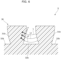
- Embodiment 1 a case where projection 31 is in the shape of an inverted truncated square pyramid is described as an example. However, it is sufficient that the peripheral surface of the projection is in a shape in which the distance from the central axis to the edge of the projection gradually increases from the base portion toward the distal end portion. In Embodiment 3, a case where the peripheral surface of the projection is convex will be described as an example.
- FIG. 6 is an enlarged cross-sectional view of peripheral surfaces of projections 31b according to Embodiment 3. Specifically, FIG. 6 is a diagram corresponding to FIG. 4 . As shown in FIG. 6 , the peripheral surface of projection 31b is convex so as to project outward. In this case, as shown in FIG. 6 , when droplet L enters between a pair of adjacent projections 31b, surface tension causes droplet L in recess 32b to be shaped to protrude toward the bottom surface of recess 32b. In droplet L, force F is generated along the tangent line of the surface of droplet L, on the peripheral surface of projection 31b.
- FIG. 6 surface positions of droplet L according to the degree of entry of droplet L into recess 32b are shown.
- the surface position of droplet L when the degree of entry into recess 32b is shallowest is represented by L, and then L1 and L2, respectively, as the degree of entry increases.
- L the peripheral surface of projection 31b is convex, as droplet L enters recess 32b more deeply as indicated by L, L1, and L2, force F changes so as to be increasingly inclined toward the distal end portion of projection 31b.
- droplet L enters recess 32b more deeply as indicated by L, L1, and L2
- force F which is increasingly inclined toward the distal end portion of projection 31b is exerted on droplet L at surface positions L, L1, and L2, thereby causing a greater tendency to move toward the distal end portion of projection 31b.
- droplet L at any of surface positions L, L1, and L2 tends to easily get out of recess 32b, and thus high liquid repellency is exhibited.
- peripheral surface shape of projection 31b is a spherical shape because this can make the above-described change of force F more prominent.
- each of projections 31 is in the shape of an inverted truncated square pyramid
- the shape of the projection can be any other shape as long as it has a flat distal end surface and a distal end portion that is larger than the base portion.
- Other shapes of the projection include an inverted polygonal frustum other than an inverted truncated square pyramid, an inverted truncated cone, and an inverted truncated elliptical cone.
- bathroom 100 is exemplified as wet-area equipment.
- wet-area equipment can be any equipment that may get wet.
- Other wet-area equipment includes, for example, equipment provided in a kitchen, a lavatory, a toilet, or a bathroom.
- equipment provided in a kitchen include a kitchen counter, a sink, a range hood, etc.
- equipment provided in a lavatory include a wash basin, a water tap, etc.
- Examples of equipment provided in a toilet include a toilet seat, a toilet bowl, etc.
- Examples of equipment provided in a bathroom include a bathtub, a bathroom door, etc.
- a wet-area equipment may be equipment that may get wet in a state of being disposed outdoors.
- resin molded body 1 is exemplified in the above-described embodiments, the resin molded body can be formed of any resin material on which laser processing can be performed.
Landscapes
- Physics & Mathematics (AREA)
- Optics & Photonics (AREA)
- Engineering & Computer Science (AREA)
- Plasma & Fusion (AREA)
- Mechanical Engineering (AREA)
- Health & Medical Sciences (AREA)
- Toxicology (AREA)
- Treatments Of Macromolecular Shaped Articles (AREA)
- Shaping Of Tube Ends By Bending Or Straightening (AREA)
- Sink And Installation For Waste Water (AREA)
- Laser Beam Processing (AREA)
Applications Claiming Priority (2)
| Application Number | Priority Date | Filing Date | Title |
|---|---|---|---|
| JP2020129948 | 2020-07-31 | ||
| PCT/JP2021/028159 WO2022025205A1 (ja) | 2020-07-31 | 2021-07-29 | 樹脂成形体、樹脂成形体の製造方法及び水廻り機器 |
Publications (4)
| Publication Number | Publication Date |
|---|---|
| EP4190482A1 EP4190482A1 (en) | 2023-06-07 |
| EP4190482A4 EP4190482A4 (en) | 2024-01-10 |
| EP4190482C0 EP4190482C0 (en) | 2025-05-21 |
| EP4190482B1 true EP4190482B1 (en) | 2025-05-21 |
Family
ID=80036320
Family Applications (1)
| Application Number | Title | Priority Date | Filing Date |
|---|---|---|---|
| EP21850065.0A Active EP4190482B1 (en) | 2020-07-31 | 2021-07-29 | Resin molded article, method for producing resin molded body, and wet-area equipment. |
Country Status (5)
| Country | Link |
|---|---|
| US (1) | US20230182372A1 (https=) |
| EP (1) | EP4190482B1 (https=) |
| JP (1) | JP7457954B2 (https=) |
| CN (1) | CN115702075A (https=) |
| WO (1) | WO2022025205A1 (https=) |
Family Cites Families (21)
| Publication number | Priority date | Publication date | Assignee | Title |
|---|---|---|---|---|
| JP4203310B2 (ja) * | 2002-12-09 | 2008-12-24 | 富士フイルム株式会社 | 防眩性反射防止フィルムの製造方法 |
| TWI242466B (en) * | 2003-08-29 | 2005-11-01 | Prec Instr Dev Ct Nat | Control device and method for controlling liquid droplets |
| US20070031639A1 (en) * | 2005-08-03 | 2007-02-08 | General Electric Company | Articles having low wettability and methods for making |
| US20070231542A1 (en) * | 2006-04-03 | 2007-10-04 | General Electric Company | Articles having low wettability and high light transmission |
| US8987632B2 (en) * | 2009-10-09 | 2015-03-24 | The United States Of America As Represented By The Administrator Of The National Aeronautics And Space Administration | Modification of surface energy via direct laser ablative surface patterning |
| JP2013517903A (ja) * | 2010-01-28 | 2013-05-20 | プレジデント アンド フェロウズ オブ ハーバード カレッジ | 微生物の付着を防止するための構造 |
| US20110287217A1 (en) * | 2010-05-21 | 2011-11-24 | Prantik Mazumder | Superoleophobic substrates and methods of forming same |
| JP2013052546A (ja) * | 2011-09-01 | 2013-03-21 | Fujifilm Corp | 撥液表面を有する構造体、インクジェットヘッドのノズルプレート、ならびに、該構造体および該ノズルプレートのクリーニング方法 |
| US10967105B2 (en) * | 2013-08-07 | 2021-04-06 | Tarek Hassan | Medical devices and instruments with non-coated superhydrophobic or superoleophobic surfaces |
| CN105792953B (zh) * | 2013-12-06 | 2018-11-09 | 依视路国际公司 | 具有纳米结构化表面的制品 |
| JP6347132B2 (ja) * | 2014-03-28 | 2018-06-27 | 大日本印刷株式会社 | 線状微細凹凸構造体、及びその製造方法 |
| CN104494134B (zh) * | 2014-12-17 | 2017-01-25 | 湖北理工学院 | 一步激光法制备接触角可调的超疏水表面材料的方法 |
| WO2016122959A2 (en) * | 2015-01-26 | 2016-08-04 | The Regents Of The University Of California | Method for manufacturing re-entrant microstructures |
| JP2017001327A (ja) * | 2015-06-12 | 2017-01-05 | Jxエネルギー株式会社 | 撥水部材 |
| JP2018035555A (ja) * | 2016-08-31 | 2018-03-08 | パナソニックIpマネジメント株式会社 | 撥水性表面材 |
| CN110573253B (zh) * | 2017-01-13 | 2021-11-02 | 赛卢拉研究公司 | 流体通道的亲水涂层 |
| JP6460274B2 (ja) * | 2017-04-07 | 2019-01-30 | 東洋製罐グループホールディングス株式会社 | 撥液性プラスチック成形体及びその製造方法 |
| ES2697919A1 (es) * | 2017-07-28 | 2019-01-29 | Bsh Electrodomesticos Espana Sa | Metodo para fabricar un componente de aparato domestico, componente de aparato domestico, aparato domestico, y dispositivo de microestructuracion por laser |
| DE102018108053A1 (de) * | 2018-04-05 | 2019-10-10 | Fraunhofer-Gesellschaft zur Förderung der angewandten Forschung eingetragener Verein | Mikrostrukturierter Gegenstand |
| JP2019188605A (ja) | 2018-04-18 | 2019-10-31 | 東洋製罐グループホールディングス株式会社 | 撥液性プラスチック成形体 |
| CN109623137B (zh) * | 2018-11-14 | 2020-07-10 | 华中科技大学 | 一种聚四氟乙烯表面水粘附力的精确连续调控方法 |
-
2021
- 2021-07-29 WO PCT/JP2021/028159 patent/WO2022025205A1/ja not_active Ceased
- 2021-07-29 JP JP2022539574A patent/JP7457954B2/ja active Active
- 2021-07-29 CN CN202180044046.1A patent/CN115702075A/zh active Pending
- 2021-07-29 US US18/012,826 patent/US20230182372A1/en not_active Abandoned
- 2021-07-29 EP EP21850065.0A patent/EP4190482B1/en active Active
Also Published As
| Publication number | Publication date |
|---|---|
| EP4190482A1 (en) | 2023-06-07 |
| WO2022025205A1 (ja) | 2022-02-03 |
| EP4190482C0 (en) | 2025-05-21 |
| CN115702075A (zh) | 2023-02-14 |
| JPWO2022025205A1 (https=) | 2022-02-03 |
| US20230182372A1 (en) | 2023-06-15 |
| EP4190482A4 (en) | 2024-01-10 |
| JP7457954B2 (ja) | 2024-03-29 |
Similar Documents
| Publication | Publication Date | Title |
|---|---|---|
| US20240366844A1 (en) | Medical devices and instruments with non-coated superhydrophobic or superoleophobic surfaces | |
| DE60208575T2 (de) | Verfahren zur herstellung eines geformten polymerartikels | |
| DE69631252T2 (de) | Befestigungselemente mit doppel-struktur | |
| US11613461B2 (en) | Textiles having a microstructured surface and garments comprising the same | |
| US20080023439A1 (en) | Hierarchically-dimensioned-microfiber-based dry adhesive materials | |
| US20100120196A1 (en) | Nano-array and fabrication method thereof | |
| KR20040100839A (ko) | 미세구조화된 표면을 가지는 고체 물체 | |
| US20050271869A1 (en) | Hierarchically-dimensioned-microfiber-based dry adhesive materials | |
| EP4190482B1 (en) | Resin molded article, method for producing resin molded body, and wet-area equipment. | |
| CN110049857A (zh) | 成型体 | |
| JP6046824B2 (ja) | 重ね合わせ複合内装部品 | |
| JP7640037B2 (ja) | 成形体、成形体の製造方法及び水廻り機器 | |
| EP4141194A1 (en) | Molded body and method for producing molded body | |
| JP2005525923A (ja) | 表面 | |
| US6343895B1 (en) | Resin net and its production method | |
| US20160256030A1 (en) | Cleaning Implement with Resilient Projections | |
| TWI705176B (zh) | 衛浴構件 | |
| TW202142325A (zh) | 極微結構化表面 | |
| US20230037550A1 (en) | Method of manufacturing processed body provided with water-repellent surface, and processed body provided with water-repellent surface | |
| JP7333660B1 (ja) | 撥水面構造 | |
| JP3188770U (ja) | 撥水性にすぐれる樹脂成形品 | |
| EP3524345B1 (de) | Füll- und/oder bewuchskörper | |
| KR20150122090A (ko) | 초소수성 및 투명성을 갖는 폴리머 구조물 및 그 제조방법 | |
| EP3782579B1 (en) | Interdental cleaning tool | |
| JP3245338U (ja) | 撥水性にすぐれる樹脂製品 |
Legal Events
| Date | Code | Title | Description |
|---|---|---|---|
| STAA | Information on the status of an ep patent application or granted ep patent |
Free format text: STATUS: THE INTERNATIONAL PUBLICATION HAS BEEN MADE |
|
| PUAI | Public reference made under article 153(3) epc to a published international application that has entered the european phase |
Free format text: ORIGINAL CODE: 0009012 |
|
| STAA | Information on the status of an ep patent application or granted ep patent |
Free format text: STATUS: REQUEST FOR EXAMINATION WAS MADE |
|
| 17P | Request for examination filed |
Effective date: 20221222 |
|
| AK | Designated contracting states |
Kind code of ref document: A1 Designated state(s): AL AT BE BG CH CY CZ DE DK EE ES FI FR GB GR HR HU IE IS IT LI LT LU LV MC MK MT NL NO PL PT RO RS SE SI SK SM TR |
|
| DAV | Request for validation of the european patent (deleted) | ||
| DAX | Request for extension of the european patent (deleted) | ||
| REG | Reference to a national code |
Ref country code: DE Ref legal event code: R079 Ref country code: DE Ref legal event code: R079 Ref document number: 602021031250 Country of ref document: DE Free format text: PREVIOUS MAIN CLASS: B23K0026352000 Ipc: B29C0059160000 |
|
| A4 | Supplementary search report drawn up and despatched |
Effective date: 20231213 |
|
| RIC1 | Information provided on ipc code assigned before grant |
Ipc: B23K 103/00 20060101ALN20231207BHEP Ipc: B23K 101/18 20060101ALN20231207BHEP Ipc: E03C 1/20 20060101ALI20231207BHEP Ipc: B23K 26/402 20140101ALI20231207BHEP Ipc: B23K 26/364 20140101ALI20231207BHEP Ipc: B23K 26/0622 20140101ALI20231207BHEP Ipc: B23K 26/352 20140101ALI20231207BHEP Ipc: B29C 59/02 20060101ALI20231207BHEP Ipc: B29C 59/16 20060101AFI20231207BHEP |
|
| GRAP | Despatch of communication of intention to grant a patent |
Free format text: ORIGINAL CODE: EPIDOSNIGR1 |
|
| STAA | Information on the status of an ep patent application or granted ep patent |
Free format text: STATUS: GRANT OF PATENT IS INTENDED |
|
| RIC1 | Information provided on ipc code assigned before grant |
Ipc: B23K 103/00 20060101ALN20240927BHEP Ipc: B23K 101/18 20060101ALN20240927BHEP Ipc: E03C 1/20 20060101ALI20240927BHEP Ipc: B23K 26/402 20140101ALI20240927BHEP Ipc: B23K 26/364 20140101ALI20240927BHEP Ipc: B23K 26/0622 20140101ALI20240927BHEP Ipc: B23K 26/352 20140101ALI20240927BHEP Ipc: B29C 59/02 20060101ALI20240927BHEP Ipc: B29C 59/16 20060101AFI20240927BHEP |
|
| INTG | Intention to grant announced |
Effective date: 20241016 |
|
| GRAS | Grant fee paid |
Free format text: ORIGINAL CODE: EPIDOSNIGR3 |
|
| GRAA | (expected) grant |
Free format text: ORIGINAL CODE: 0009210 |
|
| STAA | Information on the status of an ep patent application or granted ep patent |
Free format text: STATUS: THE PATENT HAS BEEN GRANTED |
|
| AK | Designated contracting states |
Kind code of ref document: B1 Designated state(s): AL AT BE BG CH CY CZ DE DK EE ES FI FR GB GR HR HU IE IS IT LI LT LU LV MC MK MT NL NO PL PT RO RS SE SI SK SM TR |
|
| REG | Reference to a national code |
Ref country code: GB Ref legal event code: FG4D |
|
| REG | Reference to a national code |
Ref country code: CH Ref legal event code: EP |
|
| REG | Reference to a national code |
Ref country code: DE Ref legal event code: R096 Ref document number: 602021031250 Country of ref document: DE |
|
| REG | Reference to a national code |
Ref country code: IE Ref legal event code: FG4D |
|
| U01 | Request for unitary effect filed |
Effective date: 20250619 |
|
| U07 | Unitary effect registered |
Designated state(s): AT BE BG DE DK EE FI FR IT LT LU LV MT NL PT RO SE SI Effective date: 20250630 |
|
| U20 | Renewal fee for the european patent with unitary effect paid |
Year of fee payment: 5 Effective date: 20250728 |
|
| PG25 | Lapsed in a contracting state [announced via postgrant information from national office to epo] |
Ref country code: ES Free format text: LAPSE BECAUSE OF FAILURE TO SUBMIT A TRANSLATION OF THE DESCRIPTION OR TO PAY THE FEE WITHIN THE PRESCRIBED TIME-LIMIT Effective date: 20250521 |
|
| PG25 | Lapsed in a contracting state [announced via postgrant information from national office to epo] |
Ref country code: NO Free format text: LAPSE BECAUSE OF FAILURE TO SUBMIT A TRANSLATION OF THE DESCRIPTION OR TO PAY THE FEE WITHIN THE PRESCRIBED TIME-LIMIT Effective date: 20250821 Ref country code: GR Free format text: LAPSE BECAUSE OF FAILURE TO SUBMIT A TRANSLATION OF THE DESCRIPTION OR TO PAY THE FEE WITHIN THE PRESCRIBED TIME-LIMIT Effective date: 20250822 |
|
| PG25 | Lapsed in a contracting state [announced via postgrant information from national office to epo] |
Ref country code: PL Free format text: LAPSE BECAUSE OF FAILURE TO SUBMIT A TRANSLATION OF THE DESCRIPTION OR TO PAY THE FEE WITHIN THE PRESCRIBED TIME-LIMIT Effective date: 20250521 |
|
| PG25 | Lapsed in a contracting state [announced via postgrant information from national office to epo] |
Ref country code: HR Free format text: LAPSE BECAUSE OF FAILURE TO SUBMIT A TRANSLATION OF THE DESCRIPTION OR TO PAY THE FEE WITHIN THE PRESCRIBED TIME-LIMIT Effective date: 20250521 |
|
| PG25 | Lapsed in a contracting state [announced via postgrant information from national office to epo] |
Ref country code: RS Free format text: LAPSE BECAUSE OF FAILURE TO SUBMIT A TRANSLATION OF THE DESCRIPTION OR TO PAY THE FEE WITHIN THE PRESCRIBED TIME-LIMIT Effective date: 20250821 |
|
| PG25 | Lapsed in a contracting state [announced via postgrant information from national office to epo] |
Ref country code: IS Free format text: LAPSE BECAUSE OF FAILURE TO SUBMIT A TRANSLATION OF THE DESCRIPTION OR TO PAY THE FEE WITHIN THE PRESCRIBED TIME-LIMIT Effective date: 20250921 |
|
| PG25 | Lapsed in a contracting state [announced via postgrant information from national office to epo] |
Ref country code: SM Free format text: LAPSE BECAUSE OF FAILURE TO SUBMIT A TRANSLATION OF THE DESCRIPTION OR TO PAY THE FEE WITHIN THE PRESCRIBED TIME-LIMIT Effective date: 20250521 |
|
| PG25 | Lapsed in a contracting state [announced via postgrant information from national office to epo] |
Ref country code: CZ Free format text: LAPSE BECAUSE OF FAILURE TO SUBMIT A TRANSLATION OF THE DESCRIPTION OR TO PAY THE FEE WITHIN THE PRESCRIBED TIME-LIMIT Effective date: 20250521 |
|
| PG25 | Lapsed in a contracting state [announced via postgrant information from national office to epo] |
Ref country code: SK Free format text: LAPSE BECAUSE OF FAILURE TO SUBMIT A TRANSLATION OF THE DESCRIPTION OR TO PAY THE FEE WITHIN THE PRESCRIBED TIME-LIMIT Effective date: 20250521 |
|
| REG | Reference to a national code |
Ref country code: CH Ref legal event code: H13 Free format text: ST27 STATUS EVENT CODE: U-0-0-H10-H13 (AS PROVIDED BY THE NATIONAL OFFICE) Effective date: 20260224 |
|
| PLBE | No opposition filed within time limit |
Free format text: ORIGINAL CODE: 0009261 |
|
| STAA | Information on the status of an ep patent application or granted ep patent |
Free format text: STATUS: NO OPPOSITION FILED WITHIN TIME LIMIT |
|
| REG | Reference to a national code |
Ref country code: CH Ref legal event code: L10 Free format text: ST27 STATUS EVENT CODE: U-0-0-L10-L00 (AS PROVIDED BY THE NATIONAL OFFICE) Effective date: 20260402 |