EP4187048A1 - Einbau einer nutzfahrzeugmotorhaube - Google Patents
Einbau einer nutzfahrzeugmotorhaube Download PDFInfo
- Publication number
- EP4187048A1 EP4187048A1 EP21210259.4A EP21210259A EP4187048A1 EP 4187048 A1 EP4187048 A1 EP 4187048A1 EP 21210259 A EP21210259 A EP 21210259A EP 4187048 A1 EP4187048 A1 EP 4187048A1
- Authority
- EP
- European Patent Office
- Prior art keywords
- projection
- hinge structure
- indentation
- vehicle
- locking device
- Prior art date
- Legal status (The legal status is an assumption and is not a legal conclusion. Google has not performed a legal analysis and makes no representation as to the accuracy of the status listed.)
- Pending
Links
- 238000009434 installation Methods 0.000 title description 4
- 238000007373 indentation Methods 0.000 claims description 44
- 230000007246 mechanism Effects 0.000 abstract description 2
- 238000000034 method Methods 0.000 description 5
- 230000008569 process Effects 0.000 description 5
- 230000008901 benefit Effects 0.000 description 4
- 238000001816 cooling Methods 0.000 description 3
- 230000004048 modification Effects 0.000 description 3
- 238000012986 modification Methods 0.000 description 3
- 239000000428 dust Substances 0.000 description 2
- 238000012423 maintenance Methods 0.000 description 2
- 239000000463 material Substances 0.000 description 2
- 229910000831 Steel Inorganic materials 0.000 description 1
- 230000009471 action Effects 0.000 description 1
- 238000004026 adhesive bonding Methods 0.000 description 1
- 230000009286 beneficial effect Effects 0.000 description 1
- 230000005540 biological transmission Effects 0.000 description 1
- 238000002485 combustion reaction Methods 0.000 description 1
- 238000010276 construction Methods 0.000 description 1
- 230000000694 effects Effects 0.000 description 1
- 238000011065 in-situ storage Methods 0.000 description 1
- 238000004519 manufacturing process Methods 0.000 description 1
- 229920003023 plastic Polymers 0.000 description 1
- 239000004033 plastic Substances 0.000 description 1
- 230000000717 retained effect Effects 0.000 description 1
- 239000010959 steel Substances 0.000 description 1
- 238000003466 welding Methods 0.000 description 1
Images


Classifications
-
- E—FIXED CONSTRUCTIONS
- E05—LOCKS; KEYS; WINDOW OR DOOR FITTINGS; SAFES
- E05D—HINGES OR SUSPENSION DEVICES FOR DOORS, WINDOWS OR WINGS
- E05D5/00—Construction of single parts, e.g. the parts for attachment
- E05D5/10—Pins, sockets or sleeves; Removable pins
- E05D5/12—Securing pins in sockets, movably or not
- E05D5/128—Securing pins in sockets, movably or not the pin having a recess or through-hole engaged by a securing member
-
- E—FIXED CONSTRUCTIONS
- E05—LOCKS; KEYS; WINDOW OR DOOR FITTINGS; SAFES
- E05D—HINGES OR SUSPENSION DEVICES FOR DOORS, WINDOWS OR WINGS
- E05D3/00—Hinges with pins
- E05D3/02—Hinges with pins with one pin
-
- E—FIXED CONSTRUCTIONS
- E05—LOCKS; KEYS; WINDOW OR DOOR FITTINGS; SAFES
- E05Y—INDEXING SCHEME ASSOCIATED WITH SUBCLASSES E05D AND E05F, RELATING TO CONSTRUCTION ELEMENTS, ELECTRIC CONTROL, POWER SUPPLY, POWER SIGNAL OR TRANSMISSION, USER INTERFACES, MOUNTING OR COUPLING, DETAILS, ACCESSORIES, AUXILIARY OPERATIONS NOT OTHERWISE PROVIDED FOR, APPLICATION THEREOF
- E05Y2201/00—Constructional elements; Accessories therefor
- E05Y2201/40—Motors; Magnets; Springs; Weights; Accessories therefor
- E05Y2201/47—Springs
- E05Y2201/474—Compression springs
-
- E—FIXED CONSTRUCTIONS
- E05—LOCKS; KEYS; WINDOW OR DOOR FITTINGS; SAFES
- E05Y—INDEXING SCHEME ASSOCIATED WITH SUBCLASSES E05D AND E05F, RELATING TO CONSTRUCTION ELEMENTS, ELECTRIC CONTROL, POWER SUPPLY, POWER SIGNAL OR TRANSMISSION, USER INTERFACES, MOUNTING OR COUPLING, DETAILS, ACCESSORIES, AUXILIARY OPERATIONS NOT OTHERWISE PROVIDED FOR, APPLICATION THEREOF
- E05Y2600/00—Mounting or coupling arrangements for elements provided for in this subclass
- E05Y2600/50—Mounting methods; Positioning
- E05Y2600/52—Toolless
-
- E—FIXED CONSTRUCTIONS
- E05—LOCKS; KEYS; WINDOW OR DOOR FITTINGS; SAFES
- E05Y—INDEXING SCHEME ASSOCIATED WITH SUBCLASSES E05D AND E05F, RELATING TO CONSTRUCTION ELEMENTS, ELECTRIC CONTROL, POWER SUPPLY, POWER SIGNAL OR TRANSMISSION, USER INTERFACES, MOUNTING OR COUPLING, DETAILS, ACCESSORIES, AUXILIARY OPERATIONS NOT OTHERWISE PROVIDED FOR, APPLICATION THEREOF
- E05Y2600/00—Mounting or coupling arrangements for elements provided for in this subclass
- E05Y2600/50—Mounting methods; Positioning
- E05Y2600/56—Positioning, e.g. re-positioning, or pre-mounting
-
- E—FIXED CONSTRUCTIONS
- E05—LOCKS; KEYS; WINDOW OR DOOR FITTINGS; SAFES
- E05Y—INDEXING SCHEME ASSOCIATED WITH SUBCLASSES E05D AND E05F, RELATING TO CONSTRUCTION ELEMENTS, ELECTRIC CONTROL, POWER SUPPLY, POWER SIGNAL OR TRANSMISSION, USER INTERFACES, MOUNTING OR COUPLING, DETAILS, ACCESSORIES, AUXILIARY OPERATIONS NOT OTHERWISE PROVIDED FOR, APPLICATION THEREOF
- E05Y2800/00—Details, accessories and auxiliary operations not otherwise provided for
- E05Y2800/26—Form or shape
- E05Y2800/298—Form or shape having indentations
-
- E—FIXED CONSTRUCTIONS
- E05—LOCKS; KEYS; WINDOW OR DOOR FITTINGS; SAFES
- E05Y—INDEXING SCHEME ASSOCIATED WITH SUBCLASSES E05D AND E05F, RELATING TO CONSTRUCTION ELEMENTS, ELECTRIC CONTROL, POWER SUPPLY, POWER SIGNAL OR TRANSMISSION, USER INTERFACES, MOUNTING OR COUPLING, DETAILS, ACCESSORIES, AUXILIARY OPERATIONS NOT OTHERWISE PROVIDED FOR, APPLICATION THEREOF
- E05Y2800/00—Details, accessories and auxiliary operations not otherwise provided for
- E05Y2800/26—Form or shape
- E05Y2800/33—Form or shape having protrusions
-
- E—FIXED CONSTRUCTIONS
- E05—LOCKS; KEYS; WINDOW OR DOOR FITTINGS; SAFES
- E05Y—INDEXING SCHEME ASSOCIATED WITH SUBCLASSES E05D AND E05F, RELATING TO CONSTRUCTION ELEMENTS, ELECTRIC CONTROL, POWER SUPPLY, POWER SIGNAL OR TRANSMISSION, USER INTERFACES, MOUNTING OR COUPLING, DETAILS, ACCESSORIES, AUXILIARY OPERATIONS NOT OTHERWISE PROVIDED FOR, APPLICATION THEREOF
- E05Y2900/00—Application of doors, windows, wings or fittings thereof
- E05Y2900/50—Application of doors, windows, wings or fittings thereof for vehicles
- E05Y2900/518—Application of doors, windows, wings or fittings thereof for vehicles for working vehicles
-
- E—FIXED CONSTRUCTIONS
- E05—LOCKS; KEYS; WINDOW OR DOOR FITTINGS; SAFES
- E05Y—INDEXING SCHEME ASSOCIATED WITH SUBCLASSES E05D AND E05F, RELATING TO CONSTRUCTION ELEMENTS, ELECTRIC CONTROL, POWER SUPPLY, POWER SIGNAL OR TRANSMISSION, USER INTERFACES, MOUNTING OR COUPLING, DETAILS, ACCESSORIES, AUXILIARY OPERATIONS NOT OTHERWISE PROVIDED FOR, APPLICATION THEREOF
- E05Y2900/00—Application of doors, windows, wings or fittings thereof
- E05Y2900/50—Application of doors, windows, wings or fittings thereof for vehicles
- E05Y2900/53—Type of wing
- E05Y2900/536—Hoods
Definitions
- the present invention relates to the installation of hinged body panels on utility vehicles, and particularly to hinge arrangements for relatively heavy components such as engine compartment hoods.
- Utility vehicles include, by way of example, agricultural, industrial and forestry tractors, and plant machinery.
- a utility vehicle typically includes an engine, a cooling system and one or more further components housed underneath a pivotable bonnet or hood.
- the bonnet serves to protect the engine and cooling system from the outside environment and the like.
- the hood which covers the engine compartment is generally large enough to be a substantial weight fitted on the top of the vehicle, and at a significant level above floor level so that access to the hinge structure which connects the hood to the frame is extremely limited. Coupled with the weight of the hood and the position relative to a person assembling the tractor on the production line, it is very difficult to align the hinge structure with corresponding recesses on the frame and then provide releasable fasteners such as screws to hold the hinge structure in place.
- the hinge structure includes a first portion securable to the vehicle body panel and a second portion securable to the vehicle frame, with the first and second portions being pivotally interconnected to pivot the body panel about a given axis.
- the hinge structure includes at least one projection extending from the second portion in a direction at right angles to the given axis, the at least one projection being receivable in a bore in the vehicle frame.
- the projection has an indentation for receiving a locking device extending into the indentation at an angle to the longitudinal axis of the projection.
- a problem with arrangements such as that described above is that there is still a requirement for the person (or more likely, team) installing the panel to controllably secure engagement of a locking device with the projection indentation during installation.
- a hinge structure for pivotally connecting a vehicle body panel to a vehicle frame, said hinge structure comprising a first portion securable to said vehicle body panel and a second portion securable to said vehicle frame, said first and second portions being pivotally interconnected to pivot said body panel about a given axis; said hinge structure comprising at least one projection having a longitudinal axis coincident with said given axis and receivable in a bore in said second portion, said projection being movable in the axial direction to engage an aperture in the first portion and having a first indentation for receiving a locking device extending through the second portion and into said indentation at an angle to the longitudinal axis of said projection, thereby locking the projection in engagement with the first portion.
- This arrangement with the projection being movable within the bore in the second portion until locked by engagement of the locking device, enables straightforward mounting of the body panel whilst allowing movement relative to the frame until the correct positioning is achieved (as indicated by the successful engagement of the locking device
- the locking device includes resilient biasing means such as a spring or deformable body arranged to urge the locking device into engagement with the said first indentation.
- resilient biasing means such as a spring or deformable body arranged to urge the locking device into engagement with the said first indentation.
- the projection has a second indentation, longitudinally spaced from the first indentation along the length of the projection, for receiving the locking device, wherein engagement of the locking device with the said second indentation holds the projection in spaced apart non-engaged relation with the first portion, suitably retracted into the bore in the second portion.
- a second indentation longitudinally spaced from the first indentation along the length of the projection, for receiving the locking device, wherein engagement of the locking device with the said second indentation holds the projection in spaced apart non-engaged relation with the first portion, suitably retracted into the bore in the second portion.
- the locking device may have a chamfered end to guide the locking device into engagement with the first indentation (and/or second indentation where provided) as the projection moves in the bore in the second portion.
- a single indentation this improves certainty of engagement of the locking device at a specific position along the length of the projection: with first and second indentations, where the second indentation is preferably relatively shallow, the chamfering suitably allows the locking device to be pushed out of the second indentation (recessed position) by an axially-directed force, with the end of the locking device sliding along the outer surface of the projection until the first indentation is reached and engaged (locked position).
- the projection is suitably a generally cylindrical body, with the or each of the projection indentations being provided by an annular groove in the curved surface thereof, which groove lies in a plane perpendicular to the projection longitudinal axis.
- an end of the projection movable to engage an aperture in the first portion includes a chamfered or tapered portion to guide engagement: as the tapered or chamfered portion moves into the first portion aperture, it centres the projection within the aperture and aligns mounting.
- the hinge structure may further comprise a securing device actuatable to prevent withdrawal of the locking device from engagement with the first indentation.
- This securing device which may be in the form of locking screw or bolt preventing movement of the locking device, is suitably provided to combat accidental disengagement of the locking device due to e.g. excessive vibration in the area of panel attachment.
- the present invention provides a utility or agricultural vehicle comprising a frame and wheels, an engine coupled to provide motive power driving the wheels, and at least one bodywork panel pivotably attached to the frame by at least one hinge structure as recited in any of claims 1 to 6 as appended hereto.
- the at least one body panel is a bonnet or hood extending from the hinge structure over the engine of the vehicle and, where the vehicle further comprises a user cab mounted on the frame, the second portion of the hinge structure may suitably provide a bulkhead or console portion between the engine and the cab, which bulkhead is both a structural component and also an impediment to the transmission of noise and vibration from the engine compartment to the cab.
- the at least one body panel may be pivotably attached to the frame by a pair of the hinge structures, which pair of hinge structures preferably share a common second portion.
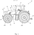
- Relative and directional terms used hereinafter such as 'forward', 'rearward', 'transverse', 'lateral' and made with respect to a virtual longitudinal vehicle axis that extends parallel to a general forward direction of travel, identified with the arrow F in Figure 1 of the attached drawings.
- Fig. 1 shows a representation of an agricultural machine, in the form of an agricultural or farm tractor 10.
- the tractor 10 comprises a user cab 12 to house an operator of the machine, an engine housing (identified generally at 14 and described further below), and a chassis or frame 16 on which the cab 12 and engine housing 14 are mounted.
- a front axle 18 carries front vehicle wheels 18A
- a rear axle 20 carries rear vehicle wheels 20A.
- the tractor will be provided with a rear three-point linkage system 22, and optionally also a front linkage 24, for the attachment of implements.
- the engine housing 14 shrouds an engine (not shown) of the tractor, which engine may be an internal combustion unit, an electric drive or a hybrid arrangement.
- the housing 14 includes an upper bonnet or hood portion 26 which extends forwardly from the cab 12 over the engine compartment (the space within the engine housing 14), and suitably provides cover for additional components therein, such as cooling systems for the vehicle.
- the bonnet or hood portion 26 is pivotably attached to the frame 16 by a hinge structure as described in detail below with reference to Figures 2 to 4 of the drawings.
- the hinge structure enables the bonnet or hood portion 26 to pivot about an axis A, which given axis extends transversely and horizontally across the vehicle perpendicular to the direction of forward travel F.
- the bonnet With the pivoting mount at A, the bonnet can be raised (as indicated by arrow B) to enable access to the engine compartment for routine maintenance or replacement of components within the engine housing 14.
- the engine housing 14 may further include one or more removable side panels 28 on each side, with the side panels being optionally attached at their respective upper edges to the lower edge of the bonnet 26.
- the side panels 28 may be secured to other components within the engine compartment such that the side panels 28 remain in situ as the bonnet 26 is raised.
- the hinge structure 30 providing the pivoting mount for the bonnet 26 is shown firstly in perspective view in Fig. 2 .
- the hinge structure 30 comprises a first portion 32 in the form of a mounting rail configured to be securable to the bonnet 26 (or another similarly mounted vehicle body panel).
- the first portion or mounting rail 32 may comprise part of a structural support framework for the bonnet 26, with the remainder of the bonnet formed from relatively lighter weight materials (thinner gauge steel, plastics etc.) to keep the overall weight of the bonnet 26 to a minimum whilst maintaining structural integrity.
- the hinge structure 30 includes a second portion 34 in the form of a cast console or bulkhead securable to the vehicle frame (16; Fig. 1 ) and generally extending transversely across the frame.
- the mounting rail and cast console (first and second portions 32, 34) are pivotally interconnected as described below to pivot the bonnet 26 about the given axis A.
- the tractor 10 comprises a pair of hinge structures 30, with the pair sharing a common cast console 34, and the two mounting rails 32 being attached to respective ones of the left and right sides of the bonnet 26.
- the hinge structure 30 comprises at least one bolt or hinge pin in the form of a projection 36, which projection is a generally cylindrical body (albeit with variations in radius described below) having a longitudinal axis coincident with the given axis A when installed.
- the projection 36 is received in a bore 38 in the cast console 34, and movable in the axial direction A to engage an aperture 40 in the mounting rail 32, which aperture 40 is suitably lined with a bearing bush 42 providing a close fit around (and support to) a distal end 36A of the projection.
- the projection 36 has a first indentation 44 in the form of an annular groove for receiving the nose portion 46A of a locking device 46, which locking device 46 extends through a respective aperture 48 in the cast console 34 and into said indentation 44 at an angle (preferably but not necessarily 90 degrees) to the longitudinal axis A of the projection 36.
- the locking device 46 may suitably be retained within the aperture 48 by threaded engagement, allowing the locking device 46 to be easily removed for exchange or maintenance if required, although more permanent fixations such as gluing or welding are considered within the scope of the present disclosure.
- the distal end 36A of the projection protrudes from the cast console 34 in engagement with the mounting rail 32 (and bearing bush 42) whilst at the same time the locking device 46 locks the projection 36 in positional engagement with the cast console 34.
- the locking device 46 includes resilient biasing means 48, preferably in the form of a coil spring (although other elastic and resiliently deformable materials may be utilized to the same effect), whereby the nose portion 46A of the locking device 46 is urged towards the projection 36 and into engagement with the first indentation 44 as the two come into alignment.
- resilient biasing means 48 preferably in the form of a coil spring (although other elastic and resiliently deformable materials may be utilized to the same effect)
- the projection 36 has a second indentation 50, longitudinally spaced from the first indentation 44 along the length of the projection, for receiving or at least interacting with the nose portion 46A of the locking device 46.
- the second indentation 50 is again preferably an annular recess or groove on the outer surface of the projection 36, wherein engagement of the nose portion 46A of the locking means with the said second indentation 50 holds the projection 36 in spaced apart non-engaged relation with the aperture in the mounting rail 32, suitably with the projection 36 retracted into the bore 38 in the cast console.
- the second indentation 50 may have the same profile as the first indentation 44, but is preferably shallower in depth as the locking action it is required to assist in is just a temporary hold during the assembly process.
- Such an arrangement facilitates the assembly process as the bonnet 26 and associated mounting rail or rails 32 may be more easily moved into position if the projection 36 remains in a retracted state until needed to engage. Protection of the end of the projection from dirt, dust and accidental damage is a further benefit.
- the locking device 46 may have a chamfered end to the nose portion 46A to guide it into engagement with the first indentation 44, and second indentation 50 as the projection 36 moves in the bore 38 in the cast console 34. With a single indentation, this improves certainty of engagement of the locking device 46 at a specific position along the length of the projection 36: with first 44 and second 50 indentations, where the second indentation is preferably relatively shallow, the chamfering suitably allows the locking device to be pushed out of the second indentation (recessed position of Fig.3 ) by an axially-directed force, with the nose portion 46A of the locking device sliding along the outer surface of the projection 36 until the first indentation 44 is reached and fully engaged (locked position of Fig. 4 ).
- the projection 36 (of the or each hinge structure 30) is, as described above, a generally cylindrical body, with the or each of the projection indentations 44, 50 being provided by an annular groove in the curved surface thereof, which groove lies in a plane perpendicular to the projection longitudinal axis A.
- the distal end 36A of the projection 36 (movable to engage the aperture 40 in the mounting rail 32) includes a chamfered or tapered portion to guide engagement: as the tapered or chamfered portion moves into the aperture, it centres the projection within the aperture and aligns mounting.
- the hinge structure 30 may further comprise a securing device (not shown) actuatable to prevent withdrawal of the locking device 46 from engagement with the first indentation 44.
- This securing device which may be in the form of locking screw or bolt preventing movement of the locking device 46 relative to the cast console 34, is suitably provided to combat accidental disengagement of the locking device due to e.g. excessive vibration in the area of panel attachment.
- a hinge structure 30 provides the pivoting mount for the bonnet 26 of an agricultural or similar vehicle.
- the hinge structure 30 comprises a mounting rail 32 configured to be securable to the bonnet 26 and a cast console or bulkhead 34 securable to the vehicle frame.
- the mounting rail 32 and cast console 34 are pivotally interconnected for rotation about an axis A.
- the hinge structure 30 comprises at least one bolt or hinge pin in the form of a projection 36, which projection is a generally cylindrical body having a longitudinal axis coincident with the given axis A when installed.
- the projection 36 is received in a bore 38 in the cast console 34, and movable in the axial direction A to engage an aperture 40 in the mounting rail 32 where it is held by a sprung locking mechanism 46.
- the vehicle comprises a pair of the hinge structures 30, with the pair sharing a common cast console 34, and the two mounting rails 32 being attached to respective ones of the left and right sides of the bonnet 26.
Landscapes
- Engineering & Computer Science (AREA)
- Mechanical Engineering (AREA)
- Superstructure Of Vehicle (AREA)
Priority Applications (1)
| Application Number | Priority Date | Filing Date | Title |
|---|---|---|---|
| EP21210259.4A EP4187048A1 (de) | 2021-11-24 | 2021-11-24 | Einbau einer nutzfahrzeugmotorhaube |
Applications Claiming Priority (1)
| Application Number | Priority Date | Filing Date | Title |
|---|---|---|---|
| EP21210259.4A EP4187048A1 (de) | 2021-11-24 | 2021-11-24 | Einbau einer nutzfahrzeugmotorhaube |
Publications (1)
| Publication Number | Publication Date |
|---|---|
| EP4187048A1 true EP4187048A1 (de) | 2023-05-31 |
Family
ID=78789743
Family Applications (1)
| Application Number | Title | Priority Date | Filing Date |
|---|---|---|---|
| EP21210259.4A Pending EP4187048A1 (de) | 2021-11-24 | 2021-11-24 | Einbau einer nutzfahrzeugmotorhaube |
Country Status (1)
| Country | Link |
|---|---|
| EP (1) | EP4187048A1 (de) |
Citations (4)
| Publication number | Priority date | Publication date | Assignee | Title |
|---|---|---|---|---|
| AT272887B (de) * | 1965-12-18 | 1969-07-25 | Ver Baubeschlag Gretsch Co | Gelenkverbindung |
| US20160208457A1 (en) * | 2015-01-21 | 2016-07-21 | Caterpillar Inc. | Actuation system for hood of a machine |
| GB2538073A (en) | 2015-05-05 | 2016-11-09 | Cnh Ind N V | Apparatus and method for attaching hinged vehicle body panel |
| CN112459644A (zh) * | 2020-12-10 | 2021-03-09 | 浙江龙纪汽车零部件股份有限公司 | 一种车门限位铰链 |
-
2021
- 2021-11-24 EP EP21210259.4A patent/EP4187048A1/de active Pending
Patent Citations (4)
| Publication number | Priority date | Publication date | Assignee | Title |
|---|---|---|---|---|
| AT272887B (de) * | 1965-12-18 | 1969-07-25 | Ver Baubeschlag Gretsch Co | Gelenkverbindung |
| US20160208457A1 (en) * | 2015-01-21 | 2016-07-21 | Caterpillar Inc. | Actuation system for hood of a machine |
| GB2538073A (en) | 2015-05-05 | 2016-11-09 | Cnh Ind N V | Apparatus and method for attaching hinged vehicle body panel |
| CN112459644A (zh) * | 2020-12-10 | 2021-03-09 | 浙江龙纪汽车零部件股份有限公司 | 一种车门限位铰链 |
Similar Documents
| Publication | Publication Date | Title |
|---|---|---|
| US6401302B1 (en) | Motor vehicle opening leaf handle | |
| US20140246468A1 (en) | Rops mount for work vehicle display interface | |
| EP2333165A1 (de) | Baugerät mit Schmiermittelinjektionsvorrichtung in der Kabine | |
| US7758104B2 (en) | Window arrangement for a construction vehicle | |
| EP3318473A1 (de) | Kotflügelanordnung für einen traktor | |
| CA2309366A1 (en) | Drive train mount adapter plate and pivot bracket | |
| JP6386979B2 (ja) | 作業車両 | |
| US9995069B2 (en) | Operator cab for machine having door with swing controlling hinge mechanism | |
| JP5654968B2 (ja) | トラクタ | |
| EP4187048A1 (de) | Einbau einer nutzfahrzeugmotorhaube | |
| US7743869B2 (en) | Mining utility transport vehicle | |
| JP2019516034A (ja) | 調節可能なヒンジ組立品 | |
| JP6139221B2 (ja) | 作業車両 | |
| US10161106B2 (en) | Platform assembly for a ground engaging tool | |
| US20140332292A1 (en) | Powered guard group for a machine | |
| US7290778B2 (en) | Cradle for steering assembly | |
| JPH11115769A (ja) | 自動車のステアリング装置 | |
| WO2018168422A1 (ja) | トラクタ | |
| US11414035B2 (en) | Work vehicle | |
| US9855976B2 (en) | Actuation system for hood of a machine | |
| EP3342939A1 (de) | Schutzsystem für ein arbeitsfahrzeug | |
| US20230382322A1 (en) | Connecting assembly for a sensor pod | |
| US20230406207A1 (en) | Method for installing and uninstalling a sensor pod | |
| US20230382315A1 (en) | Apparatus for break off sensor pod | |
| US20230382314A1 (en) | Universal bracket for a sensor pod |
Legal Events
| Date | Code | Title | Description |
|---|---|---|---|
| STAA | Information on the status of an ep patent application or granted ep patent |
Free format text: STATUS: UNKNOWN |
|
| PUAI | Public reference made under article 153(3) epc to a published international application that has entered the european phase |
Free format text: ORIGINAL CODE: 0009012 |
|
| STAA | Information on the status of an ep patent application or granted ep patent |
Free format text: STATUS: THE APPLICATION HAS BEEN PUBLISHED |
|
| AK | Designated contracting states |
Kind code of ref document: A1 Designated state(s): AL AT BE BG CH CY CZ DE DK EE ES FI FR GB GR HR HU IE IS IT LI LT LU LV MC MK MT NL NO PL PT RO RS SE SI SK SM TR |
|
| STAA | Information on the status of an ep patent application or granted ep patent |
Free format text: STATUS: REQUEST FOR EXAMINATION WAS MADE |
|
| 17P | Request for examination filed |
Effective date: 20231130 |
|
| RBV | Designated contracting states (corrected) |
Designated state(s): AL AT BE BG CH CY CZ DE DK EE ES FI FR GB GR HR HU IE IS IT LI LT LU LV MC MK MT NL NO PL PT RO RS SE SI SK SM TR |