EP4186715A1 - Pneumatique - Google Patents
Pneumatique Download PDFInfo
- Publication number
- EP4186715A1 EP4186715A1 EP23150764.1A EP23150764A EP4186715A1 EP 4186715 A1 EP4186715 A1 EP 4186715A1 EP 23150764 A EP23150764 A EP 23150764A EP 4186715 A1 EP4186715 A1 EP 4186715A1
- Authority
- EP
- European Patent Office
- Prior art keywords
- tire
- electronic component
- component unit
- radial direction
- bead
- Prior art date
- Legal status (The legal status is an assumption and is not a legal conclusion. Google has not performed a legal analysis and makes no representation as to the accuracy of the status listed.)
- Granted
Links
- 239000011324 bead Substances 0.000 claims abstract description 144
- 239000000853 adhesive Substances 0.000 claims abstract description 65
- 230000001070 adhesive effect Effects 0.000 claims abstract description 65
- 239000000945 filler Substances 0.000 claims abstract description 40
- 239000011347 resin Substances 0.000 claims abstract description 27
- 229920005989 resin Polymers 0.000 claims abstract description 27
- 229920001971 elastomer Polymers 0.000 claims description 125
- 239000002184 metal Substances 0.000 claims description 19
- 229910052751 metal Inorganic materials 0.000 claims description 19
- 239000000758 substrate Substances 0.000 claims description 16
- 230000002787 reinforcement Effects 0.000 claims description 10
- 239000004020 conductor Substances 0.000 claims description 5
- 239000010408 film Substances 0.000 description 69
- 229910000831 Steel Inorganic materials 0.000 description 36
- 239000010959 steel Substances 0.000 description 36
- 238000004073 vulcanization Methods 0.000 description 34
- 239000010410 layer Substances 0.000 description 21
- 238000001035 drying Methods 0.000 description 20
- 238000004519 manufacturing process Methods 0.000 description 18
- 238000009434 installation Methods 0.000 description 15
- 239000011248 coating agent Substances 0.000 description 14
- 238000000576 coating method Methods 0.000 description 14
- 238000004891 communication Methods 0.000 description 14
- 230000000694 effects Effects 0.000 description 11
- 239000000835 fiber Substances 0.000 description 10
- 238000000465 moulding Methods 0.000 description 10
- 241000254043 Melolonthinae Species 0.000 description 9
- 239000000470 constituent Substances 0.000 description 9
- 230000007423 decrease Effects 0.000 description 6
- 238000002360 preparation method Methods 0.000 description 6
- 238000012360 testing method Methods 0.000 description 6
- 230000001012 protector Effects 0.000 description 5
- 239000000463 material Substances 0.000 description 4
- 239000004952 Polyamide Substances 0.000 description 3
- 230000002411 adverse Effects 0.000 description 3
- 239000012298 atmosphere Substances 0.000 description 3
- 238000005516 engineering process Methods 0.000 description 3
- 238000011049 filling Methods 0.000 description 3
- 238000005304 joining Methods 0.000 description 3
- 239000006082 mold release agent Substances 0.000 description 3
- 229920002647 polyamide Polymers 0.000 description 3
- 229920001721 polyimide Polymers 0.000 description 3
- 239000002356 single layer Substances 0.000 description 3
- VYPSYNLAJGMNEJ-UHFFFAOYSA-N Silicium dioxide Chemical compound O=[Si]=O VYPSYNLAJGMNEJ-UHFFFAOYSA-N 0.000 description 2
- 230000008859 change Effects 0.000 description 2
- 230000007547 defect Effects 0.000 description 2
- 238000007598 dipping method Methods 0.000 description 2
- 230000006872 improvement Effects 0.000 description 2
- 239000011368 organic material Substances 0.000 description 2
- 238000003825 pressing Methods 0.000 description 2
- 230000035939 shock Effects 0.000 description 2
- 238000003860 storage Methods 0.000 description 2
- RYGMFSIKBFXOCR-UHFFFAOYSA-N Copper Chemical compound [Cu] RYGMFSIKBFXOCR-UHFFFAOYSA-N 0.000 description 1
- CTQNGGLPUBDAKN-UHFFFAOYSA-N O-Xylene Chemical compound CC1=CC=CC=C1C CTQNGGLPUBDAKN-UHFFFAOYSA-N 0.000 description 1
- 239000002253 acid Substances 0.000 description 1
- 230000009471 action Effects 0.000 description 1
- 229920006231 aramid fiber Polymers 0.000 description 1
- 230000001680 brushing effect Effects 0.000 description 1
- 229910052799 carbon Inorganic materials 0.000 description 1
- 239000006229 carbon black Substances 0.000 description 1
- 229910052802 copper Inorganic materials 0.000 description 1
- 239000010949 copper Substances 0.000 description 1
- 230000001747 exhibiting effect Effects 0.000 description 1
- 230000002349 favourable effect Effects 0.000 description 1
- 229910052736 halogen Inorganic materials 0.000 description 1
- 150000002367 halogens Chemical class 0.000 description 1
- 238000003475 lamination Methods 0.000 description 1
- 239000003550 marker Substances 0.000 description 1
- 238000002156 mixing Methods 0.000 description 1
- 239000000203 mixture Substances 0.000 description 1
- 238000012986 modification Methods 0.000 description 1
- 230000004048 modification Effects 0.000 description 1
- 239000012766 organic filler Substances 0.000 description 1
- 239000003960 organic solvent Substances 0.000 description 1
- 230000002093 peripheral effect Effects 0.000 description 1
- 229920000728 polyester Polymers 0.000 description 1
- 229920006149 polyester-amide block copolymer Polymers 0.000 description 1
- 239000009719 polyimide resin Substances 0.000 description 1
- 229920000642 polymer Polymers 0.000 description 1
- 230000009467 reduction Effects 0.000 description 1
- 230000003014 reinforcing effect Effects 0.000 description 1
- 238000000926 separation method Methods 0.000 description 1
- 239000000377 silicon dioxide Substances 0.000 description 1
- 239000010409 thin film Substances 0.000 description 1
- 230000007704 transition Effects 0.000 description 1
- 238000011179 visual inspection Methods 0.000 description 1
- 239000008096 xylene Substances 0.000 description 1
Images


Classifications
-
- B—PERFORMING OPERATIONS; TRANSPORTING
- B60—VEHICLES IN GENERAL
- B60C—VEHICLE TYRES; TYRE INFLATION; TYRE CHANGING; CONNECTING VALVES TO INFLATABLE ELASTIC BODIES IN GENERAL; DEVICES OR ARRANGEMENTS RELATED TO TYRES
- B60C13/00—Tyre sidewalls; Protecting, decorating, marking, or the like, thereof
- B60C13/003—Tyre sidewalls; Protecting, decorating, marking, or the like, thereof characterised by sidewall curvature
- B60C13/004—Tyre sidewalls; Protecting, decorating, marking, or the like, thereof characterised by sidewall curvature of the internal side of the tyre
-
- B—PERFORMING OPERATIONS; TRANSPORTING
- B60—VEHICLES IN GENERAL
- B60C—VEHICLE TYRES; TYRE INFLATION; TYRE CHANGING; CONNECTING VALVES TO INFLATABLE ELASTIC BODIES IN GENERAL; DEVICES OR ARRANGEMENTS RELATED TO TYRES
- B60C19/00—Tyre parts or constructions not otherwise provided for
-
- B—PERFORMING OPERATIONS; TRANSPORTING
- B29—WORKING OF PLASTICS; WORKING OF SUBSTANCES IN A PLASTIC STATE IN GENERAL
- B29D—PRODUCING PARTICULAR ARTICLES FROM PLASTICS OR FROM SUBSTANCES IN A PLASTIC STATE
- B29D30/00—Producing pneumatic or solid tyres or parts thereof
- B29D30/0061—Accessories, details or auxiliary operations not otherwise provided for
-
- B—PERFORMING OPERATIONS; TRANSPORTING
- B60—VEHICLES IN GENERAL
- B60C—VEHICLE TYRES; TYRE INFLATION; TYRE CHANGING; CONNECTING VALVES TO INFLATABLE ELASTIC BODIES IN GENERAL; DEVICES OR ARRANGEMENTS RELATED TO TYRES
- B60C15/00—Tyre beads, e.g. ply turn-up or overlap
- B60C15/0009—Tyre beads, e.g. ply turn-up or overlap features of the carcass terminal portion
- B60C15/0027—Tyre beads, e.g. ply turn-up or overlap features of the carcass terminal portion with low ply turn-up, i.e. folded around the bead core and terminating at the bead core
-
- B—PERFORMING OPERATIONS; TRANSPORTING
- B60—VEHICLES IN GENERAL
- B60C—VEHICLE TYRES; TYRE INFLATION; TYRE CHANGING; CONNECTING VALVES TO INFLATABLE ELASTIC BODIES IN GENERAL; DEVICES OR ARRANGEMENTS RELATED TO TYRES
- B60C9/00—Reinforcements or ply arrangement of pneumatic tyres
- B60C9/02—Carcasses
-
- B—PERFORMING OPERATIONS; TRANSPORTING
- B29—WORKING OF PLASTICS; WORKING OF SUBSTANCES IN A PLASTIC STATE IN GENERAL
- B29D—PRODUCING PARTICULAR ARTICLES FROM PLASTICS OR FROM SUBSTANCES IN A PLASTIC STATE
- B29D30/00—Producing pneumatic or solid tyres or parts thereof
- B29D30/0061—Accessories, details or auxiliary operations not otherwise provided for
- B29D2030/0077—Directly attaching monitoring devices to tyres before or after vulcanization, e.g. microchips
-
- B—PERFORMING OPERATIONS; TRANSPORTING
- B60—VEHICLES IN GENERAL
- B60C—VEHICLE TYRES; TYRE INFLATION; TYRE CHANGING; CONNECTING VALVES TO INFLATABLE ELASTIC BODIES IN GENERAL; DEVICES OR ARRANGEMENTS RELATED TO TYRES
- B60C5/00—Inflatable pneumatic tyres or inner tubes
- B60C5/12—Inflatable pneumatic tyres or inner tubes without separate inflatable inserts, e.g. tubeless tyres with transverse section open to the rim
- B60C5/14—Inflatable pneumatic tyres or inner tubes without separate inflatable inserts, e.g. tubeless tyres with transverse section open to the rim with impervious liner or coating on the inner wall of the tyre
Definitions
- the present invention relates to a tire.
- Patent Document 1 discloses a tire made by arranging a transponder for obtaining information for identifying the tire on a tire inner circumferential side of a bead part.
- Patent Document 1 Japanese Unexamined Patent Application, Publication No. H07-137510
- the technology shown in Patent Document 1 it is possible to embed a transponder without deviating from a predetermined position.
- the transponder serving as an electronic component unit is embedded in the neighborhood of a bead core.
- the bead core is an annular member formed by wrapping around several times bead wires made of metal. Therefore, in the technology shown in Patent Document 1, there is a possibility of flaws in the electronic component unit occurring such as a decline in communication performance due to the adverse effects of the bead core made of metal.
- the present invention has been made taking account of the above problem, and an object thereof is to provide a tire which can suppress the occurrence of flaws in an electronic component unit arranged in a tire.
- a tire of the present invention includes: a pair of beads having a bead core and bead filler extending to an outer side in a tire-radial direction of the bead core; a carcass ply extending from one bead to another bead; an inner liner arranged at a tire inner cavity side of the carcass ply; and an electronic component unit pasted to a tire inner cavity side of the inner liner, in which the electronic component unit is arranged at a tire-radial direction position distanced at least 5.0 mm to the outer side in the tire-radial direction from a tire-radial direction outside end of the bead core.
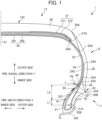
- FIG. 1 is a view showing a half section in a tire-width direction of a tire 1 according to the present embodiment. Since the basic structure of the tire 1 is left/right symmetrical in the cross-section of the tire-width direction, a cross-sectional view of the right half is shown herein.
- the reference symbol S1 is the tire equatorial plane.
- the tire equatorial plane S1 is a plane orthogonal to the tire rotation axis, and is positioned in the center of the tire-width direction.
- tire-width direction is a direction parallel to the tire rotation axis, and is the left/right direction of the paper plane of the cross-sectional view in FIG. 1 .
- it is illustrated as the tire-width direction X.
- inner side of tire-width direction is a direction approaching the tire equatorial plane S1, and is the left side of the paper plane in FIG. 1 .
- Outer side of tire-width direction is a direction distancing from the tire equatorial plane S1, and is the right side of the paper plane in FIG. 1 .
- tire-radial direction is a direction perpendicular to the tire rotation axis, and is the vertical direction in the paper plane of FIG. 1 .
- FIG. 1 it is illustrated as the tire-width direction X.
- inner side of tire-width direction is a direction approaching the tire equatorial plane S1, and is the left side of the paper plane in FIG. 1 .
- Outer side of tire-width direction is a direction dis
- tire-radial direction Y it is illustrated as the tire-radial direction Y.
- outer side of tire-radial direction is a direction distancing from the tire rotation axis, and is the upper side of the paper plane in FIG. 1 .
- Inner side of tire-radial direction is a direction approaching the tire rotation axis, and is the lower side of the paper plane in FIG. 1 .
- the cross-sectional view of FIG. 1 is a tire-width direction cross-sectional view (tire meridian axis cross-sectional view) in a state mounting the tire to a standard rim, and filling the standard internal pressure.
- standard rim indicates a rim serving as a standard decided by JATMA to correspond to the tire size.
- standard internal pressure is 180 kPa in the case of the tire being for a passenger vehicle, for example.
- the tire 1 is a tire for passenger cars, for example, and includes a pair of beads 11 provided at both sides in the tire-width direction, a sidewall 12 which extends from each of the beads 11 to the outer side in the tire-radial direction; and annular tread 13 which connects to the outer side in the tire-radial direction of each of the sidewalls 12 and extends in the circumferential direction of the tire constituting the tire tread (contact patch with road surface R) 13C.
- FIG. 2 shows an enlarged cross-sectional view in the periphery in a tire-radial direction inside region of the bead 11 and sidewall 12 of the tire 1 of the present embodiment shown in FIG. 1 .
- the bead 11 includes a bead core 21, and bead filler 22 extending to the outer side in the tire-radial direction of the bead core 21.
- the bead core 21 is an annular member formed by wrapping around several times bead wires made of metal coated with rubber, and is a member which plays a role of fixing the tire 1 filled with air to the rim 100 of a wheel.
- the bead filler 22 is a rubber member of tapered tip shape, extending to the outer side in the tire-radial direction of the bead core 21.
- the bead filler 22 has a tire-radial direction outside end 22A and a tire-radial direction inside end 22B.
- the tire-radial direction inside end 22B of the bead filler 22 contacts with the tire-radial direction outside end 21A of the bead core 21.
- the bead filler 22 is a member provided in order to raise the rigidity of the bead peripheral part and to ensure high maneuverability and stability.
- the bead filler 22 is configured by rubber of higher hardness than the surrounding rubber members, for example.
- the modulus of rubber constituting the bead filler 22 is higher than at least the modulus of rubber constituting the inner liner 29 described later and the rubber constituting the sidewall 30.
- the modulus indicates 100% elongation modulus (M100) under a 23°C atmosphere, measured in accordance with "3.7 stress at a given elongation, S" of JIS K6251:2010.
- a carcass ply 23 bridging between the pair of beads 11 is embedded inside of the tire 1.
- the carcass ply 23 configures a ply serving as the backbone of the tire 1, and is embedded within the tire 1, in a form passing through the pair of sidewalls 12 and the tread 13 between the pair of beads 11.
- the carcass ply 23 includes the ply body 24 which extends from one bead 11 to the other bead 11 and exists between the tread 13 and bead 11; and the ply folding part 25 which is folded back around the bead core 21.
- the ply folding part 25 is overlapped with the ply body 24 in the region of the sidewall 12.
- a ply folding part 25 has an end 25A.
- the end 25A of the ply folding part 25 is positioned in a region of the sidewall 12.
- the carcass ply 23 is configured by a plurality of ply cords extending in the tire-width direction.
- a plurality of ply cords is arranged side by side in a tire circumferential direction.
- This ply cord is configured by an insulated organic fiber cord such as polyester or polyamide, or the like, and is covered by topping rubber.
- the carcass ply 23 of the present embodiment is a single-layer structure carcass ply 23 including one layer of a ply body 24.
- the carcass ply 23 may be a multi-layer structure carcass ply 23 including a plurality of layers of ply body 24.
- the bead 11 further includes rim strip rubber 32.
- the rim strip rubber 32 is provided so as to cover the carcass ply 23 provided around the bead core 21.
- the rim strip rubber 32 is provided so as to cover the inner side in the tire-width direction, inner side in the tire-radial direction and the outer side in the tire-width direction of the carcass ply 23 in the vicinity of the bead core 21.
- the rim strip rubber 32 has a first end 32A arranged at an outer side in the tire-width direction of the ply folding part 25, and a second end 32C arranged on the inner side in the tire-width direction of the ply body 24.
- the first end 32A configures a tire-radial direction outside end 32A of the rim strip rubber 32.
- a part of the rim strip rubber 32 configures an outer wall surface of the tire 1.
- the rim strip rubber 32 upon the tire 1 being mounted to a wheel, is a rubber member in which the outer side in the tire-width direction and the inner side in the tire-radial direction thereof contact with the rim 100 of the wheel.
- the modulus of rubber constituting the rim strip rubber 32 is higher than at least the modulus of rubber constituting the inner liner 29 described later, and the rubber constituting the side-wall rubber 30.
- the side-wall 12 includes the side-wall rubber 30 arranged on the outer side in the width direction of the carcass ply 23.
- the side-wall rubber 30 is a rubber member configuring the outer wall surface of the tire 1.
- the side-wall rubber 30 has a tire-radial direction outside end 30A and tire-radial direction inside end 30B.
- This side-wall rubber 30 is a portion which bends the most upon the tire 1 exhibiting a cushioning action, and usually flexible rubber having fatigue resistance is adopted therein.
- the tread 13 includes a steel belt 26 as a belt arranged on the outer side in the tire-radial direction of the carcass ply 23, a cap ply 27 arranged on the outer side in the tire-radial direction of the steel belt 26, and tread rubber 28 arranged on the outer side in the tire-radial direction of the cap ply 27.
- the steel belt 26 is configured by a plurality of steel cords covered by rubber. By providing the steel belts 26, the rigidity of the tire 1 is ensured, and the contact state of the road surface with the tread 13 improves.
- the steel belt 26 of the present embodiment is configured by a two-layer structure from a steel belt 261 on an inner side and a steel belt 262 on an outer side.
- the steel belt 26 may be a single-layer structure, or may be a structure of three or more layers. It should be noted that a belt made using a tire cord or the like made using aramid fiber may be used in place of the steel belt 26 made using steel belts.
- the steel belt 261 on the inner side is wider than the steel belt 262 on the outer side. Therefore, the tire-width direction outside end of the steel belt 261 on the inner side includes the tire-width direction outside end 26A of the steel belt 26.
- the cap ply 27 is a member arranged on the outer side in the tire-radial direction of the steel belt 26, and has a function as a belt reinforcement layer.
- the cap ply 27 is configured by an insulative organic fiber layer such as polyamide fiber, and is covered by topping rubber. By providing the cap ply 27, it is possible to achieve an improvement in durability and reduction in load noise while traveling.
- the cap ply 27 of the present embodiment is configured by a two-layer structure from a cap ply 271 on the outer side and a cap ply 272 on the inner side.
- the cap ply 272 on the inner side exists only in a tire-width direction outside region, and a central part in the tire-width direction is outlined.
- the cap ply 272 on the inner side may be a cap ply of the same structure as the cap ply 271 on the outer side not having an outlined part.
- the cap ply 27 may be a single-layer structure, or may be a structure of three or more layers.
- the tire-width direction outside end 27A of the cap ply 27 extends more to the outer side in the tire-width direction than the tire-width direction outside end 26A of the steel belt 26.
- the tread rubber 28 is a member constituting tire tread (contact patch with road surface R) 13C.
- the tread rubber 28 has a tire-width direction outside end 28A.
- a tread pattern (not shown) constituted by a plurality of grooves is provided to the tire tread 13C of the tread rubber 28.
- an inner liner 29 as a rubber layer constituting an inner wall surface of the tire 1 is provided to the tire inner cavity side of the carcass ply 23.
- the inner liner 29 is configured by air permeation resistant rubber, whereby the air inside the tire inner cavity is prevented from leaking to outside.
- the sidewall rubber 30 of the sidewall 12 extends towards the tread 13.
- the tread rubber 28 of the tread 13 extends towards the sidewall 12.
- the tread rubber 28 and sidewall rubber 30 enter a layered state, on the tire outer surface side of a partial region of the carcass ply 23.
- the sidewall rubber 30 and tread rubber 28 are in a layered state in order, on the tire outer surface side of the carcass ply 23.
- the rim strip rubber 32 and sidewall rubber 30 arranged on the outer side in the tire-radial direction of the rim strip rubber 32 are arranged.
- the surface on the outer side in the tire-width direction of the rim strip rubber 32 and the surface on the outer side in the tire-width direction of the side-wall rubber 30 form the outer surface of the tire 1.
- the tire-radial direction outside end 32A of the rim strip rubber 32 is arranged more to the outer side in the tire-radial direction than the tire-radial direction outside end 22A of the bead filler 22. It is thereby possible to more effectively suppress local deformation from occurring in the vicinity of the rim mounting part.
- a rim protector 33 which has an apex part 33A projecting to the outer side in the tire-width direction and continuously extending in a ring shape in the tire circumferential direction is provided in this transition region vicinity.
- the apex part 33A of the rim protector 33 is provided at a boundary portion between the rim strip rubber 32 and side-wall rubber 30.
- the position of the apex part 33A of the rim protector 33 matches the position of the tire-radial direction inside end 30B of the side-wall rubber 30.
- the rim protector 33 has a function of protecting the rim from external damage.
- the tire 1 of the present embodiment has an electronic component unit 50.
- the electronic component unit 50 is pasted to the tire inner cavity side 29C of the inner liner 29.
- the electronic component unit 50 of the present embodiment is an RFID tag unit, for example.
- FIGS. 3A to 3C are views for explaining the electronic component unit 50.
- FIG. 3A is a view looking at the electronic component unit 50 from one side.
- FIG. 3B is a cross-sectional view showing a cross section along the line IIIB-IIIB in FIG. 3A.
- FIG. 3C is a cross-sectional view showing a cross section along the line IIIC-IIIC in FIG. 3A .
- the electronic component unit 50 includes an electronic component 40, and a flexible film 45 (a resin film 45) which covers at least part of the electronic component 40. It should be noted that, in FIG. 3A , the electronic component 40 is shown by a hidden line due to being covered by a first flexible film 451 constituting the flexible film 45.
- the electronic component 40 includes a flexible substrate 41, IC chip 42 and antenna 43.
- the electronic component 40 of the present embodiment is an RFID tag, for example.
- the flexible substrate 41 is a film-like substrate having pliability.
- a polyimide resin can be used, for example.
- the IC chip 42 of the present embodiment is an RFID chip.
- the IC chip 42 is mounted to the flexible substrate 41.
- the IC chip 42 includes a communication circuit and a storage unit. In a storage part inside the IC chip 42, identification information such as a manufacturing number and part number is stored.
- the antenna 43 is a printed antenna configured from conductive material printed in a predetermined pattern on the flexible substrate 41. This predetermined pattern, for example, may be linear, wavelike or spiral. The antenna 43 is established at an antenna length optimized according to the frequency band, etc. to be used. The antenna 43 is electrically connected with the IC chip 42. The material constituting the antenna 43 may be a conductive material such as copper, for example. By using such a printed antenna as the antenna 43, it is possible to thin the thickness of the electronic component 40 and electronic component unit 50.
- the antenna 43 is not limited to a printed antenna, and may be various antennas such as a coil spring antenna, plate antenna or rod antenna.
- the electronic component 40 does not necessarily have a flexible substrate 41, i.e. the electronic component 40 may be configured by the IC chip 42 and antenna 43.
- the electronic component 40 of the present embodiment at least includes the IC chip 42 and the antenna 43.
- the electronic component 40 thereby performs wireless communication with a reader that is not illustrated serving as external equipment.
- the electronic component 40 of the present embodiment may be a passive-type transponder.
- the flexible film 45 of the present embodiment has a first flexible film 451 and a second flexible film 452.
- the first flexible film 451 covers one side (top surface) of the electronic component 40.
- the second flexible film 452 covers the other side (back surface) of the electronic component 40.
- the electronic component 40 is interposed by the first flexible film 451 and second flexible film 452 constituting the flexible film 45.
- the one side (top surface) of the electronic component 40 is a surface of the flexible substrate 41, and is a mounting face to which the IC chip is mounted.
- the antenna 43 is also printed on the surface of the flexible substrate 41.
- the other side (back surface) of the electronic component 40 is the back surface of the flexible substrate 41, and is a non-mounting face for the IC chip 42.
- the electronic component 40 is preferably entirely covered by the flexible film 45 configured by the first flexible film 451 and second flexible film 452, as shown in the present embodiment.
- the electronic component 40 may have at least part thereof covered by the flexible film 45.
- constituting the flexible film 45 by only the first flexible film 451 a situation may be established in which one side (top surface) of the electronic component 40, i.e. mounting face of the flexible substrate 41, is covered by the first flexible film 451.
- the electronic component 40 is also thereby protected.
- the first flexible film 451 and second flexible film 452 configuring the flexible film 45 are resin films.
- the first flexible film 451 and second flexible film 452 are preferably polyimide films, for example.
- Polyimide film is superior in heat resistance and has moderate flexibility and a spring characteristic; therefore, it is suitable as a member protecting the electronic component 40.
- the thickness t1 of the first flexible film 451 and the thickness t2 of the second flexible film 452 are preferably at least 50 ⁇ m and no more than 750 pm, respectively.
- the thickness t3 of the entire flexible film 45 i.e. thickness t3 of portion overlapping the first flexible film 451 and second flexible film 452, is preferably at least 100 ⁇ m and no more than 1500 ⁇ m. It is thereby possible to suitably protect the electronic component 40, while imparting moderate flexibility to follow the changes in shape of the tire inner cavity side 29C of the inner liner 29.
- the thickness of the flexible film 45 may be at least 50 ⁇ m and no more than 750 ⁇ m.
- the overall thickness of the flexible film 45 may be at least 50 ⁇ m and no more than 1500 ⁇ m.
- FIGS. 4A and 4B are views showing the electronic component unit 50 pasted to the tire inner cavity side 29C of the inner liner 29.
- FIG. 4A is a view when looking at the electronic component unit 50 pasted to the tire inner cavity side 29C of the inner liner 29 from the tire inner cavity towards the tire outer surface side.
- FIG. 4B is a cross-sectional view showing a cross section along the line IVB-IVB in FIG. 4A .
- the electronic component unit 50 is pasted via a vulcanizing adhesive 60 on the tire inner cavity side 29C of the inner liner 29.
- the flexible film 45 is configured by the first flexible film 451 and second flexible film 452, and the vulcanizing adhesive 60, second flexible film 452, electronic component 40 and first flexible film 451 are arranged in order on the tire inner cavity side 29C of the inner liner 29.
- the vulcanizing adhesive 60 may be made by blending a vulcanization accelerator and acid acceptor into a rubber component.
- the vulcanizing adhesive 60 may be made by dispersing a polymeric material, organic material and filler as a composition into an organic solvent system such as xylene.
- a polymeric material and organic material halogen-based polymers, etc. can be used.
- filler carbon black, silica, etc. can be used.
- the thickness of the vulcanizing adhesive 60 joining the inner liner 29 and electronic component unit 50 is preferably no more than 30 ⁇ m. If the thickness of the vulcanizing adhesive 60 exceeds 30 pm, the flexibility of the vulcanizing adhesive 60 after vulcanization declines, and will hardly follow changes in shape of the tire inner cavity side 29C of the inner liner 29. By establishing the thickness of the vulcanizing adhesive 60 as no more than 30 ⁇ m, moderate flexibility of the vulcanizing adhesive 60 is ensured, and will tend to follow changes in shape of the tire inner cavity side 29C of the inner liner 29. Even if the tire 1 deforms during tire use, it is thereby possible to suppress the occurrence of flaws such that the electronic component unit 50 detaching from the inner liner 29.
- the thickness of the vulcanizing adhesive 60 is more preferably at least 10 ⁇ m and no more than 30 ⁇ m. By establishing the thickness as at least 10 pm, the adhesive strength rises, and it is possible to suppress the occurrence of a situation such that the end, etc. of the electronic component unit 50 are partially peeled off.
- the thickness of the vulcanizing adhesive 60 is preferably thinner than the thickness of the flexible film 45. It is thereby possible to suppress the occurrence of flaws such as the electronic component unit 50 detaching from the inner liner 29, caused by the lowness of flexibility of the vulcanizing adhesive 60 itself.
- the hardness after vulcanization of the vulcanizing adhesive 60 is preferably at least the hardness of the inner liner 29, and no more than the hardness of the flexible film 45.
- the gradient in hardness thereby becomes gentle, and a shock absorbing effect can be obtained. Therefore, even if the tire 1 repeatedly deforms, the stress acting on the electronic component 40 is suppressed, and it is possible to improve the durability of the electronic component 40.
- the electronic component unit 50 is arranged in an orientation such that the longitudinal direction of the electronic component unit 50, i.e. longitudinal direction of the antenna 43, faces a direction corresponding to the circumferential direction of the tire 1.
- the longitudinal direction of the antenna 43 becomes the circumferential direction of the tire 1 or the direction of the tangential line relative to the circumferential direction of the tire 1, i.e. direction orthogonal to the paper plane of the cross-sectional views of FIGS. 1 and 2 .
- the electronic component unit 50 has at least a part thereof arranged at a position in the tire-radial direction distanced at least 5.0 mm to the outer side in the tire-radial direction from the tire-radial direction outside end 21A of the bead core 21.
- the electronic component unit 50 of the present embodiment is arranged more to the outer side in the tire-radial direction than the tire-radial direction position P1 distanced by a predetermined distance L1 to the outer side in the tire-radial direction from the tire-radial direction outside end 21A of the bead core 21, on the tire inner cavity side 29C of the inner liner 29.
- the predetermined distance L1 is 5.0 mm.
- an entire portion of the electronic component 40 is preferably arranged at a tire-radial direction position distanced at least 5.0 mm to the outer side in the tire-radial direction from the tire-radial direction outside end 21A of the bead core 21.
- FIG. 5 shows the result of examining the relationship of the communication distance relative to the separation distance of the RFID tag as the electronic component 40 from the tire-radial direction outside end 21A of the bead core 21.
- the communication distance on the vertical axis is a value indexing the communication distance with the longest communication distance as 100. It is preferable if this value is at least 40, and more preferably at least 60.
- the electronic component unit 50 is preferably arranged at a tire-radial direction position separated by at least 5.0 mm to the outer side in the tire-radial direction from the tire-radial direction outside end 21A of the bead core 21, in the tire inner cavity side 29C of the inner liner 29. It is thereby possible to suppress a decline in communication performance from adverse effects of a bead core made of metal.
- the electronic component unit 50 is preferably arranged more to the outer side in the tire-radial direction than the tire-radial direction position P1 distanced by 5.0 mm to the outer side in the tire-radial direction from the tire-radial direction outside end 21A of the bead core 21, and more to the inner side in the tire-radial direction than a position P2 on the tire inner cavity side of the inner liner 29 constituting the bead thickest part T.
- at least part of the electronic component unit 50 is arranged more to the inner side in the tire-radial direction than the position P2 on the tire inner cavity side of the inner liner 29 constituting the bead thickest part T.
- At least part of the electronic component unit 50 is arranged within a region of range L2 shown in FIGS. 1 and 2 . More preferably, the entire portion of the electronic component 40 is arranged within the domain of range L2.
- bead thickest part T is a portion in which a distance (thickness) from the tire inner cavity side 29C of the inner liner 29 until the tire outer surface becomes the longest, when drawing a normal vector from the tire inner cavity side 29C of the inner liner 29, in a tire-width direction cross-sectional view shown in FIGS. 1 and 2 .
- a thick portion passing through the apex part 33A (tire-radial direction inside end 30B of the side-wall rubber 30) of the rim protector 33 is the bead thickest part T.
- the cross-sectional view of FIG. 1 is a tire-width direction cross-sectional view (tire meridian axis cross-sectional view) in an unloaded state mounting the tire to a standard rim, and filling the standard internal pressure.
- FIG. 6 is a view for explaining the motion of the tire inner cavity side 29C of the inner liner 29, in the case of the tire 1 deforming.
- the left-side view of FIG. 6 is a tire-width direction cross-sectional view of an unloaded state mounting the tire 1 to a standard rim, and filling the standard internal pressure.
- the bold line 29C1 in this figure is a line indicating the tire inner cavity side 29C of the inner liner 29 in the aforementioned unloaded state.
- the center view in FIG. 6 is a view for explaining the change in shape of the tire inner cavity side 29C of the inner liner 29, in the case of the tire 1 deforming.
- the line indicating the tire inner cavity side 29C in the aforementioned unloaded state is shown by the bold line 29C1 in this figure.
- the line indicating the tire inner cavity side 29C when the tire 1 widens in the tire-width direction and makes a flat shape, by a strong force acting from the road surface on the tread 13, etc. is shown by the two-dot chain line 29C2.
- the line indicating the tire inner cavity side 29C after a strong force acts on the tread 13 from the road surface, when the tire 1 is released from this force, and becomes a shape such that stretches in the tire-radial direction by recoil thereof is shown by the two-dot chain line 29C3.
- the region R2 in FIG. 6 which is a region corresponding to the range L2 shown in FIGS. 1 and 2 , is a region in which the electronic component unit is arranged in the present embodiment.
- the curve of the tire inner cavity side 29C of the inner liner 29 hardly changes relatively, even when the tire 1 deforms.
- the motion of the tire inner cavity side 29C of the inner liner 29 becomes mainly motion such that collapses inwards. Therefore, in the case of pasting the electronic component unit 50 to this region R2, force such that compresses and force such that pulls the electronic component unit 50 hardly occurs even when the tire 1 deforms. In other words, force such that the electronic component unit 50 detaches from the tire inner cavity side 29C of the inner liner 29 hardly occurs.
- the electronic component unit 50 is arranged in an orientation such that the longitudinal direction of the antenna 43 faces a direction corresponding to the circumferential direction of the tire 1. Consequently, force such that the electronic component unit 50 detaches from the tire inner cavity side 29C of the inner liner 29 hardly occurs.
- the electronic component unit 50 is arranged more to an inner side in the tire-radial direction than the tire-radial direction position of the tire-radial direction outside end 32A of the rim strip rubber 32.
- the electronic component unit 50 comes to be arranged at the inner side in the tire-width direction of the rim strip rubber 32 configured by rubber of high modulus or the vicinity thereof, deformation of the inner liner 29 at the periphery of the electronic component unit 50 becomes smaller.
- the entire portion of the electronic component 40 is preferably arranged more to the inner side in the tire-radial direction than the tire-radial direction position of the tire-radial direction outside end 32A of the rim strip rubber 32.
- the electronic component unit 50 is arranged more to the inner side in the tire-radial direction than the tire-radial direction position of the tire-radial direction outside end 22A of the bead filler 22.
- the electronic component unit 50 comes to be arranged at the inner side in the tire-width direction of the bead filler 22 configured by rubber of high modulus or in the vicinity thereof, deformation of the inner liner 29 at the periphery of the electronic component unit 50 becomes smaller.
- the entire portion of the electronic component 40 is preferably arranged more to the inner side in the tire-radial direction than the tire-radial direction position of the tire-radial direction outside end 22A of the bead filler 22.
- FIG. 7 is a flowchart for explaining the manufacturing method for the tire 1 of the present embodiment.
- the manufacturing method for the tire 1 of the present embodiment includes: a tire constituent member preparation step S11 of preparing tire constituent members; a molding step S12 of assembling the tire constituent members and molding a green tire; a coating step S13 of performing coating on the molded green tire; a vulcanization step S14 of vulcanizing the green tire which was coated after molding; and a testing step S15 of testing the vulcanized tire.
- the manufacturing method of the tire 1 of the present embodiment further includes: an electronic component unit preparation step S21 of preparing the electronic component unit 50; an adhesive coating step S22 of coating the vulcanizing adhesive onto the electronic component unit 50; a drying step S23 of drying the electronic component unit 50 on which the adhesive was coated, and preparing a dried electronic component unit 50 which has been dried for at least a predetermined time; and an electronic component unit installation step S24 of installing the dried electronic component unit 50 onto the rubber members serving as the tire constituent members.
- the tire constituent members including the rubber members constituting the tire 1 are prepared.
- the rubber members such as the bead filler 22, tread rubber 28, inner liner 29, side-wall rubber 30 and rim strip rubber 32 are in the state of raw rubber prior to vulcanization.
- the tire constituent members including the rubber members constituting the tire 1 are assembled, and the green tire is molded.
- a mold release agent is coated onto the inner surface of the green tire molded by the molding step S12.
- the bladder and tire are thereby preventing from sticking together.
- the green tire coated by the coating step S13 is vulcanized by a vulcanization device.
- the green tire is vulcanized by heat and pressure being applied inside of the vulcanization device.
- the bladder which is a bag-like pressing member is arranged at an inside space (inner cavity) of the green tire. The bladder inflates within the inside space of the green tire, by high-temperature, high-pressure pressurizing medium being supplied inside.
- test criteria for example, test criteria such as uniformity, dynamic balance and visual inspection can be exemplified.
- the electronic component unit 50 is prepared.
- the electronic component unit 50 having the electronic component 40 and flexible film 45 covering at least part of the electronic component 40 is prepared.
- a vulcanizing adhesive 60 prior to curing is coated onto the electronic component unit 50.
- the vulcanizing adhesive 60 is coated onto the second flexible film 452 (refer to FIG. 4B ) covering the back surface (back surface of flexible substrate 41) of the electronic component 40.
- the vulcanizing adhesive 60 is coated by brushing, dipping or the like. For example, by defining the number of times of dipping, it is possible to control the coating film thickness.
- the vulcanizing adhesive 60 is preferably coated so as to have a thickness after vulcanization of at least 10 ⁇ m and no more than 30 ⁇ m.
- the electronic component unit 50 on which the vulcanizing adhesive 60 prior to curing was coated is dried.
- the vulcanizing adhesive 60 coated on the electronic component unit 50 dries in a state of a coated thin film.
- the dried electronic component unit 50 which was dried for at least a predetermined time is prepared. This predetermined time is 1 hour, for example, in the case of the thickness of the vulcanizing adhesive 60 being no more than 30 ⁇ m.
- the electronic component unit 50 which has been dried for at least 1 hour becomes the dried electronic component unit 50.
- the dried electronic component unit 50 is installed to the rubber members prior to vulcanization.
- This electronic component unit installation step S24 is conducted in the middle or before and after the molding step S12.
- the electronic component unit 50 may be installed to the rubber members prior to being assembled, or may be installed to the rubber members during assembly at an intermediate stage which is a green tire.
- the electronic component unit 50 may be installed to the rubber members after being assembled into a green tire. It thereby enters a state in which the electronic component unit 50 is installed to the green tire assembled by the molding step S12.
- the green tire including the rubber members to which the dried electronic component unit 50 was installed is vulcanized.
- the electronic component unit 50 and rubber members are thereby joined.
- the vulcanizing adhesive 60 dried by the drying step S23 tends to temporarily adhere to the rubber members prior to vulcanization. Consequently, it is possible to improve the workability of the work for pasting the electronic component unit 50.
- the dried vulcanizing adhesive 60 integrates with the rubber members in the subsequent vulcanization step S14. In other words, in the vulcanization step S14, by heat and pressure being applied, the rubber member and vulcanizing adhesive 60 are vulcanized and joined together. Consequently, it is possible to raise the joining strength between the electronic component unit 50 and rubber members.
- the electronic component unit 50 on which the vulcanizing adhesive 60 was coated may be dried under a room-temperature environment.
- the electronic component unit 50 on which the vulcanizing adhesive 60 was coated is preferably dried in an atmosphere of at least 60°C and no higher than 80°C. It should be noted that, if dried in an atmosphere exceeding 90°C, it is not preferable since the vulcanization promoter blended into the vulcanizing adhesive 60 starts reaction.
- drying step S23 it is preferable to dry a plurality of the electronic component units 50. Then, in the electronic component unit installation step S24, it is preferable to pick up from among the plurality of electronic component units 50 the dried electronic component unit 50 which was dried for at least a predetermined time and install to the rubber members. Even in a case of providing the drying step S23, it is thereby possible to suppress a decline in yield cycle time.
- the dried electronic component unit 50 it is preferable for the dried electronic component unit 50 to be distinguished from the electronic component units 50 for which the drying time has not elapsed the predetermined time, and to be picked out.
- the plurality of electronic component units 50 in a state with the vulcanizing adhesive 60 coated is arranged within a predetermined area.
- the predetermined area may be a workbench, or may be a thermostatic oven for performing temperature management. Then, by attaching a marker such as a making time of the electronic component unit 50 made in the drying step S23 near the electronic component unit 50, a dried electronic component unit 50 and an electronic component unit 50 for which the drying time has not elapsed the predetermined time may be distinguished.
- the dried electronic component unit 50 is pasted to the tire inner cavity side 29C of the inner liner 29 prior to vulcanization.
- the RFID tag unit is provided to the tire 1 as the electronic component unit 50; however, the electronic component unit 50 provided to the tire is not limited to an RFID tag unit.
- it may be an electronic component unit having various electronic components such as a sensor that performs wireless communication. It is not preferable for the electronic component unit 50 to detach from the tire 1.
- the electronic component 40 is near a conductive member, there is a possibility of a performance change in the electronic component 40 arising, and becoming difficult to maintain the characteristics of the electronic component 40.
- the electronic component 40 may be a piezoelectric element or strain sensor.
- the configuration and manufacturing method of the present embodiment are compatible with various types of tires.
- a tire including a flipper as a reinforced fiber layer provided so as to envelop the bead core 21.
- the flipper is a member which raises the rigidity of the bead 11, and the pressure bonding property between the bead 11 and rim improves by providing the flipper.
- the flipper is arranged so as to be sandwiched between the bead core 21 and carcass ply 23 provided around the bead core 21.
- the flipper is arranged so as to cover at least part on the inner side in the tire-width direction of the bead filler 22 and at least part on the outer side in the tire-width direction of the bead filler 22.
- the flipper is configured by an organic fiber coated layer including insulative organic fibers of polyester, polyamide or the like.
- the tire 1 of the present embodiment has the following configuration.
- the tire 1 of the present embodiment includes a steel side ply 37 serving as a metal reinforcement layer.
- FIG. 8 is a view showing a half section in a tire-width direction of the tire 1 according to the present embodiment.
- FIG. 9 is an enlarged cross-sectional view in the vicinity of a tire-radial direction inside region of the bead 11 and side-wall 12 of the tire 1 of the present embodiment shown in FIG. 8 .
- the tire 1 of the present embodiment includes a steel side ply 37 serving as a metal reinforcement layer between the ply folding part 25 and bead filler 22.
- a chafer 31 is provided to be separated as an independent member from the rim strip rubber 32.
- the lamination sequence of the tread rubber 28 and side-wall rubber 30 differs in the movement region of the side-wall 12 and tread 13.
- the side-wall rubber 30 and tread rubber 28 are in a state layered in order, on the tire outer surface side of the carcass ply 23.
- the chafer 31 is provided so as to cover the carcass ply 23 provided around the bead core 21.
- the chafer 31 is provided so as to cover the inner side in the tire-width direction, inner side in the tire-radial direction and outer side in the tire-width direction of the carcass ply 23 at the periphery of the bead core 21.
- the chafer 31 has a first end 31A arranged on the outer side in the tire-width direction of the ply folding part 25 of the carcass ply 23, and a second end 31C arranged at the inner side in the tire-width direction of the ply body 24 of the carcass ply 23.
- the first end 31A of the chafer 31 is arranged so as to be sandwiched between the ply folding part 25 of the carcass ply 23 and the rim strip rubber 32.
- the second end 31C of the chafer 31 is arranged so as to be sandwiched between the ply body 24 of the carcass ply 23 and the inner liner 29.
- the chafer 31 is configured from rubber into which fibers were kneaded, or rubber of high modulus, for example, and the relative strength is high among constituent members constituting the tire 1. For example, the strength is higher than the inner liner 29 and side-wall rubber 30 described later.
- the rim strip rubber 32 of the present embodiment is arranged on the outer side in the tire-width direction of the chafer 31 and the ply folding part 25 of the carcass ply 23, and upon the tire 1 being mounted to a wheel, the outer side in the tire-width direction thereof makes contact with the rim 100 of the wheel.
- the rim strip rubber 32 has a tire-radial direction outside end 32A and tire-radial direction inside end 32B.
- the outer side in the tire-radial direction of this rim strip rubber 32 connects to the side-wall rubber 30.
- the chafer 31 is provided to be separated as an independent member from the rim strip rubber 32.
- the steel side ply 37 serving as a metal reinforcement layer is arranged between the ply folding part 25 of the carcass ply 23, and the outer side in the tire-width direction of the bead filler 22.
- the steel side ply 37 has a function of reinforcing the bead 11.
- the steel side ply 37 has a tire-radial direction outside end 37A and a tire-radial direction inside end 37B.
- the tire-radial direction outside end 37A of the steel side ply 37 is more to an outer side in the tire-radial direction than the tire-radial direction outside end 22A of the bead filler 22, and located more to the inner side in the tire-radial direction than the end 25A of the ply folding part 25.
- the steel side ply 37 has a portion arranged to be sandwiched between the outer side in the tire-width direction of the bead core 21 and the ply folding part 25, and a portion arranged to be sandwiched between the outer side in the tire-width direction of the bead filler 22 and the ply folding part 25.
- the steel side ply 37 further has a portion arranged to be sandwiched between the ply body 24 and the ply folding part 25.
- the steel side ply 37 of the present embodiment is configured by a metal fiber cord layer containing metal fibers.
- the steel side ply 37 is configured to include a plurality of metal cords formed by twisting a plurality of metal fibers, and topping rubber integrated by coating the plurality of metal cords.
- the electronic component unit 50 has at least a part thereof arranged at a tire-radial direction position distanced at least 5.0 mm from the tire-radial direction outside end 21A of the bead core 21 to the outer side in the tire-radial direction.
- the electronic component unit 50 of the present embodiment is arranged more to an outer side in the tire-radial direction than the tire-radial direction position P1 distanced by a predetermined distance L1 from the tire-radial direction outside end 21A of the bead core 21 to the outer side in the tire-radial direction, on the tire inner cavity side 29C of the inner liner 29.
- the predetermined distance L1 is 5.0 mm.
- an entire portion of the electronic component 40 is preferably arranged at a tire-radial direction position distanced at least 5.0 mm to the outer side in the tire-radial direction from the tire-radial direction outside end 21A of the bead core 21.
- the electronic component unit 50 is arranged more to the inner side in the tire-radial direction than a tire-radial direction position P3 of the tire-radial direction outside end 37A of the steel side ply 37, on the tire inner cavity side 29C of the inner liner 29.
- at least part of the electronic component unit 50 is arranged more to the inner side in the tire-radial direction than the tire-radial direction position P3 of the tire-radial direction outside end 37A of the steel side ply 37.
- at least part of the electronic component unit 50 is arranged within a region of the range L3 shown in FIGS. 8 and 9 . More preferably, the entire portion of the electronic component 40 is arranged within the region of range L3.
- the electronic component unit 50 comes to be arranged at the inner side in the tire-width direction of the steel side ply 37 or the vicinity thereof, the deformation of the inner liner 29 at the periphery of the electronic component unit 50 becomes smaller. Consequently, the force such that the electronic component unit 50 detaches from the tire inner cavity side 29C of the inner liner 29 hardly occurs.
- the electronic component unit 50 is arranged more to the inner side in the tire-radial direction than the tire-radial direction position of the tire-radial direction outside end 22A of the bead filler 22.
- the electronic component unit 50 comes to be arranged at the inner side in the tire-width direction of the bead filler 22 configured from high modulus rubber or in the vicinity thereof, deformation of the inner liner 29 at the periphery of the electronic component unit 50 becomes smaller.
- the entire portion of the electronic component 40 is preferably arranged more to the inner side in the tire-radial direction than the tire-radial direction position of the tire-radial direction outside end 22A of the bead filler 22.
- the electronic component unit 50 is arranged more to the inner side in the tire-radial direction than the tire-radial direction position of the tire-radial direction outside end 32A of the rim strip rubber 32.
- the electronic component unit 50 comes to be arranged at the inner side in the tire-width direction of the rim strip rubber 32 configured by rubber of high modulus or the vicinity thereof, deformation of the inner liner 29 at the periphery of the electronic component unit 50 becomes smaller.
- the entire portion of the electronic component 40 is preferably arranged more to the inner side in the tire-radial direction than the tire-radial direction position of the tire-radial direction outside end 32A of the rim strip rubber 32.
- the electronic component unit 50 of the present embodiment has a curved shape formed in a state adhered with the inner liner 29.
- FIG. 10A is a view showing the electronic component unit 50 pasted to the inner liner 29 of the tire according to the present embodiment.
- FIG. 10B is a cross-sectional view showing a cross section along the line XB-XB in FIG. 10A .
- the electronic component unit 50 of the present embodiment has a curved shape formed in a state adhered with the inner liner 29.
- a projecting part 50D protruding to a tire outer surface side is formed as this curved shape.
- the projecting part 50D formed so as to sink into the inner liner 29 is formed.
- the adhesion between the inner liner 29 and electronic component unit 50 improves, and it is thereby possible to suppress detaching of the electronic component unit 50.
- the step dimension t5 of the curved shape is preferably larger than the thickness of the vulcanizing adhesive 60. The adhesion between the inner liner 29 and electronic component unit 50 thereby further improves.
- the step dimension t5 of the curved shape may be larger than the thickness of the flexible film 45 constituting the electronic component unit 50. The adhesion between the inner liner 29 and electronic component unit 50 thereby further improves.
- This curved shape is formed in the vulcanization step S14.
- the dried electronic component unit 50 is installed to the rubber member prior to vulcanization in the electronic component unit installation step S24. Prior to the vulcanization step S14, it is a state in which the electronic component unit 50 is installed to the green tire.
- the green tire to which the electronic component unit 50 was installed is vulcanized by a vulcanization device.
- a bladder which is a bag-like pressing member is arranged at an inside space (inner cavity) of the green tire.
- the bladder inflates within the inside space of the green tire, by high-temperature, high-pressure pressurizing medium being supplied inside.
- the tire inner cavity side 29C of the inner liner 29 is thereby pressurized in the direction of the outer mold (tire outer surface side), while being heated.
- a projection of predetermine height is provided to the outer surface of the bladder.
- the projection of this bladder thereby presses the electronic component unit 50 pasted to the inner cavity surface 29C of the inner liner 29.
- the projecting part 50D serving as the curved shape is formed at the electronic component unit 50.
- a groove 29D is formed in the inner cavity surface 29C of the inner liner 29.
- the curved shape may be a projecting part which protrudes to the side of the tire inner cavity.
- the adhesion between the inner liner 29 and electronic component unit 50 also thereby improves, and it is possible to suppress detaching of the electronic component unit 50.
- This case provides a groove to the outer surface of the bladder. It is thereby possible to form in the electronic component unit 50 a projecting part protruding to the side of the tire inner cavity, as the curved shape formed in a state adhering with the inner liner 29.
- the curved shape formed in the electronic component unit 50 is not limited to a projecting part, and may be a so-called step-bend (Z-bend) shape or the like.
- the tire of the present invention can be adopted as various types of tires such as for cars, light trucks, trucks and buses, it is particularly suitable as a tire of a truck, bus, etc. It should be noted that the present invention is not limited to the above-mentioned embodiments, and even if conducting modifications, improvements, etc. within a scope which can achieve the object of the present invention, it is also encompassed in the scope of the present invention.
Landscapes
- Engineering & Computer Science (AREA)
- Mechanical Engineering (AREA)
- Tires In General (AREA)
- Tyre Moulding (AREA)
Applications Claiming Priority (2)
| Application Number | Priority Date | Filing Date | Title |
|---|---|---|---|
| JP2020193146A JP2022081916A (ja) | 2020-11-20 | 2020-11-20 | タイヤ |
| EP21208405.7A EP4000965B1 (fr) | 2020-11-20 | 2021-11-16 | Pneumatique |
Related Parent Applications (2)
| Application Number | Title | Priority Date | Filing Date |
|---|---|---|---|
| EP21208405.7A Division-Into EP4000965B1 (fr) | 2020-11-20 | 2021-11-16 | Pneumatique |
| EP21208405.7A Division EP4000965B1 (fr) | 2020-11-20 | 2021-11-16 | Pneumatique |
Publications (2)
| Publication Number | Publication Date |
|---|---|
| EP4186715A1 true EP4186715A1 (fr) | 2023-05-31 |
| EP4186715B1 EP4186715B1 (fr) | 2024-04-03 |
Family
ID=78649235
Family Applications (2)
| Application Number | Title | Priority Date | Filing Date |
|---|---|---|---|
| EP23150764.1A Active EP4186715B1 (fr) | 2020-11-20 | 2021-11-16 | Pneumatique |
| EP21208405.7A Active EP4000965B1 (fr) | 2020-11-20 | 2021-11-16 | Pneumatique |
Family Applications After (1)
| Application Number | Title | Priority Date | Filing Date |
|---|---|---|---|
| EP21208405.7A Active EP4000965B1 (fr) | 2020-11-20 | 2021-11-16 | Pneumatique |
Country Status (4)
| Country | Link |
|---|---|
| US (1) | US20220161608A1 (fr) |
| EP (2) | EP4186715B1 (fr) |
| JP (1) | JP2022081916A (fr) |
| CN (1) | CN114516245B (fr) |
Citations (5)
| Publication number | Priority date | Publication date | Assignee | Title |
|---|---|---|---|---|
| JPH07137510A (ja) | 1993-11-19 | 1995-05-30 | Bridgestone Corp | トランスポンダを内蔵した空気入りタイヤ |
| US20040159383A1 (en) * | 2002-06-11 | 2004-08-19 | Adamson John David | Method for embedding a radio frequency antenna in a tire, and an antenna for embedding in a tire |
| US8430142B2 (en) * | 2009-02-25 | 2013-04-30 | The Goodyear Tire & Rubber Company | Environmentally resistant assembly containing an electronic device for use in a tire |
| US20150083811A1 (en) * | 2008-10-20 | 2015-03-26 | Compagnie Generale Des Etablissements Michelin | Power component and instrumented tyre |
| FR3059606A1 (fr) * | 2016-12-05 | 2018-06-08 | Compagnie Generale Des Etablissements Michelin | Module de communication radiofrequence pour pneumatique |
Family Cites Families (29)
| Publication number | Priority date | Publication date | Assignee | Title |
|---|---|---|---|---|
| DE3539489A1 (de) * | 1985-11-07 | 1987-05-14 | Uniroyal Englebert Gmbh | Verfahren zum ermitteln eines veraenderlichen luftdruckwertes eines fahrzeugluftreifens und anzeigen eines druckwertes |
| US5181975A (en) * | 1991-03-27 | 1993-01-26 | The Goodyear Tire & Rubber Company | Integrated circuit transponder with coil antenna in a pneumatic tire for use in tire identification |
| US5483827A (en) * | 1994-06-03 | 1996-01-16 | Computer Methods Corporation | Active integrated circuit transponder and sensor apparatus for sensing and transmitting vehicle tire parameter data |
| US5971046A (en) * | 1997-09-17 | 1999-10-26 | Bridgestone/Firestone, Inc. | Method and apparatus for bonding an active tag to a patch and a tire |
| JP4548870B2 (ja) * | 1998-02-27 | 2010-09-22 | 株式会社ブリヂストン | 空気入りタイヤ |
| CN1774349A (zh) * | 2003-03-14 | 2006-05-17 | 株式会社普利司通 | 充气轮胎及其安装方法 |
| JP4561287B2 (ja) * | 2004-10-05 | 2010-10-13 | 横浜ゴム株式会社 | 空気入りタイヤ |
| JP4599150B2 (ja) * | 2004-12-14 | 2010-12-15 | 住友ゴム工業株式会社 | 電子部品の収納具を具える空気入りタイヤ |
| JP4555673B2 (ja) * | 2004-12-14 | 2010-10-06 | 住友ゴム工業株式会社 | 電子部品の収納具を具える空気入りタイヤ、及びその製造方法 |
| US20060290505A1 (en) * | 2005-03-01 | 2006-12-28 | Kevin Conwell | RFID tire label |
| JP2006248340A (ja) * | 2005-03-09 | 2006-09-21 | Bridgestone Corp | アンテナ及び空気入りタイヤ |
| US7419557B2 (en) * | 2005-09-08 | 2008-09-02 | The Goodyear Tire & Rubber Company | Method for protecting tire innerliner using thermoformable film coated with pressure-sensitive adhesive |
| JP2010269670A (ja) * | 2009-05-20 | 2010-12-02 | Bridgestone Corp | 無線通信装置及び無線通信装置を備えるタイヤ |
| JP2012066632A (ja) * | 2010-09-21 | 2012-04-05 | Bridgestone Corp | タイヤ |
| JP5394415B2 (ja) * | 2011-01-26 | 2014-01-22 | 東洋ゴム工業株式会社 | 空気入りラジアルタイヤ |
| CA2878838C (fr) * | 2012-07-13 | 2019-04-23 | Bridgestone Corporation | Pneu |
| BR112016002381B1 (pt) * | 2013-08-05 | 2022-02-08 | Pirelli Tyre S.P.A. | Dispositivo de monitoramento de pneus e pneu para rodas de veículos, e, métodos para instalar uma unidade eletrônica em um pneu para rodas de veículos e para manter uma unidade eletrônica restrita a um pneu para rodas de veículos |
| JP5771681B2 (ja) * | 2013-12-27 | 2015-09-02 | 株式会社ブリヂストン | 空気入りタイヤ |
| WO2016035709A1 (fr) * | 2014-09-05 | 2016-03-10 | 横浜ゴム株式会社 | Pneumatique |
| EP3201841A1 (fr) * | 2014-09-29 | 2017-08-09 | Avery Dennison Corporation | Étiquette rfid de suivi de pneus |
| EP3240701A4 (fr) * | 2014-12-30 | 2018-08-08 | Bridgestone Americas Tire Operations, LLC | Article en caoutchouc comprenant un mécanisme de fixation à pièces électroniques |
| JP6612141B2 (ja) * | 2016-01-25 | 2019-11-27 | 株式会社ブリヂストン | Rfidタグ内蔵タイヤ |
| DE102017209550A1 (de) * | 2017-06-07 | 2018-12-13 | Continental Reifen Deutschland Gmbh | Fahrzeugreifen |
| EP3677452B1 (fr) * | 2017-09-12 | 2023-04-19 | Sumitomo Rubber Industries, Ltd. | Pneumatique |
| JP2019061489A (ja) * | 2017-09-26 | 2019-04-18 | 株式会社フェニックスソリューション | Rfタグ、rfタグ付き樹脂製品、rfタグ付きゴム製品 |
| WO2019220063A2 (fr) * | 2018-05-17 | 2019-11-21 | Compagnie Generale Des Etablissements Michelin | Procede de fabrication d'un pneumatique equipe d'un module de communication radiofrequence |
| DE102018215458A1 (de) * | 2018-09-12 | 2020-03-12 | Continental Reifen Deutschland Gmbh | Verfahren zur Herstellung eines Fahrzeugreifens |
| JP6594507B1 (ja) * | 2018-10-03 | 2019-10-23 | Toyo Tire株式会社 | タイヤおよびタイヤの製造方法 |
| TWI674205B (zh) * | 2018-10-19 | 2019-10-11 | 相豐科技股份有限公司 | 輪胎電子標籤 |
-
2020
- 2020-11-20 JP JP2020193146A patent/JP2022081916A/ja active Pending
-
2021
- 2021-11-16 EP EP23150764.1A patent/EP4186715B1/fr active Active
- 2021-11-16 EP EP21208405.7A patent/EP4000965B1/fr active Active
- 2021-11-17 CN CN202111360417.5A patent/CN114516245B/zh active Active
- 2021-11-18 US US17/529,408 patent/US20220161608A1/en active Pending
Patent Citations (5)
| Publication number | Priority date | Publication date | Assignee | Title |
|---|---|---|---|---|
| JPH07137510A (ja) | 1993-11-19 | 1995-05-30 | Bridgestone Corp | トランスポンダを内蔵した空気入りタイヤ |
| US20040159383A1 (en) * | 2002-06-11 | 2004-08-19 | Adamson John David | Method for embedding a radio frequency antenna in a tire, and an antenna for embedding in a tire |
| US20150083811A1 (en) * | 2008-10-20 | 2015-03-26 | Compagnie Generale Des Etablissements Michelin | Power component and instrumented tyre |
| US8430142B2 (en) * | 2009-02-25 | 2013-04-30 | The Goodyear Tire & Rubber Company | Environmentally resistant assembly containing an electronic device for use in a tire |
| FR3059606A1 (fr) * | 2016-12-05 | 2018-06-08 | Compagnie Generale Des Etablissements Michelin | Module de communication radiofrequence pour pneumatique |
Also Published As
| Publication number | Publication date |
|---|---|
| CN114516245B (zh) | 2024-01-02 |
| US20220161608A1 (en) | 2022-05-26 |
| EP4000965B1 (fr) | 2023-07-12 |
| CN114516245A (zh) | 2022-05-20 |
| EP4186715B1 (fr) | 2024-04-03 |
| EP4000965A2 (fr) | 2022-05-25 |
| EP4000965A3 (fr) | 2022-06-29 |
| JP2022081916A (ja) | 2022-06-01 |
Similar Documents
| Publication | Publication Date | Title |
|---|---|---|
| EP3632705B1 (fr) | Pneumatique et procédé de fabrication de pneumatique | |
| CN110978899B (zh) | 轮胎及轮胎的制造方法 | |
| EP3632666B1 (fr) | Procédé de fabrication de pneu | |
| CN110978897B (zh) | 轮胎 | |
| CN111376660B (zh) | 轮胎及轮胎的制造方法 | |
| US20200398616A1 (en) | Tire | |
| CN112109503A (zh) | 轮胎 | |
| EP3730320B1 (fr) | Pneumatique | |
| EP3736120B1 (fr) | Pneumatique et procédé de fabrication de pneumatiques | |
| EP4186715B1 (fr) | Pneumatique | |
| EP4000966B1 (fr) | Pneumatique | |
| US11858298B2 (en) | Tire | |
| EP3632707B1 (fr) | Procédé de fabrication de pneumatique et pneumatique | |
| EP3674109B1 (fr) | Pneumatique et procédé de fabrication de pneumatiques | |
| JP7200149B2 (ja) | タイヤ | |
| JP2022081915A (ja) | タイヤの製造方法 | |
| EP4019293B1 (fr) | Pneumatique | |
| EP3730319B1 (fr) | Pneumatique et procédé de fabrication de pneumatiques |
Legal Events
| Date | Code | Title | Description |
|---|---|---|---|
| PUAI | Public reference made under article 153(3) epc to a published international application that has entered the european phase |
Free format text: ORIGINAL CODE: 0009012 |
|
| STAA | Information on the status of an ep patent application or granted ep patent |
Free format text: STATUS: THE APPLICATION HAS BEEN PUBLISHED |
|
| AC | Divisional application: reference to earlier application |
Ref document number: 4000965 Country of ref document: EP Kind code of ref document: P |
|
| AK | Designated contracting states |
Kind code of ref document: A1 Designated state(s): AL AT BE BG CH CY CZ DE DK EE ES FI FR GB GR HR HU IE IS IT LI LT LU LV MC MK MT NL NO PL PT RO RS SE SI SK SM TR |
|
| STAA | Information on the status of an ep patent application or granted ep patent |
Free format text: STATUS: REQUEST FOR EXAMINATION WAS MADE |
|
| 17P | Request for examination filed |
Effective date: 20230817 |
|
| RBV | Designated contracting states (corrected) |
Designated state(s): AL AT BE BG CH CY CZ DE DK EE ES FI FR GB GR HR HU IE IS IT LI LT LU LV MC MK MT NL NO PL PT RO RS SE SI SK SM TR |
|
| RIC1 | Information provided on ipc code assigned before grant |
Ipc: B29D 30/00 20060101ALN20231020BHEP Ipc: B60C 5/14 20060101ALN20231020BHEP Ipc: B60C 19/00 20060101AFI20231020BHEP |
|
| GRAP | Despatch of communication of intention to grant a patent |
Free format text: ORIGINAL CODE: EPIDOSNIGR1 |
|
| STAA | Information on the status of an ep patent application or granted ep patent |
Free format text: STATUS: GRANT OF PATENT IS INTENDED |
|
| RIC1 | Information provided on ipc code assigned before grant |
Ipc: B29D 30/00 20060101ALN20231108BHEP Ipc: B60C 5/14 20060101ALN20231108BHEP Ipc: B60C 19/00 20060101AFI20231108BHEP |
|
| INTG | Intention to grant announced |
Effective date: 20231213 |
|
| GRAS | Grant fee paid |
Free format text: ORIGINAL CODE: EPIDOSNIGR3 |
|
| GRAA | (expected) grant |
Free format text: ORIGINAL CODE: 0009210 |
|
| STAA | Information on the status of an ep patent application or granted ep patent |
Free format text: STATUS: THE PATENT HAS BEEN GRANTED |
|
| AC | Divisional application: reference to earlier application |
Ref document number: 4000965 Country of ref document: EP Kind code of ref document: P |
|
| AK | Designated contracting states |
Kind code of ref document: B1 Designated state(s): AL AT BE BG CH CY CZ DE DK EE ES FI FR GB GR HR HU IE IS IT LI LT LU LV MC MK MT NL NO PL PT RO RS SE SI SK SM TR |
|
| REG | Reference to a national code |
Ref country code: CH Ref legal event code: EP |
|
| REG | Reference to a national code |
Ref country code: DE Ref legal event code: R096 Ref document number: 602021011434 Country of ref document: DE |