EP4182228B1 - Sitzeinheit mit rohrförmiger sitzbasisstruktur - Google Patents
Sitzeinheit mit rohrförmiger sitzbasisstruktur Download PDFInfo
- Publication number
- EP4182228B1 EP4182228B1 EP21739397.4A EP21739397A EP4182228B1 EP 4182228 B1 EP4182228 B1 EP 4182228B1 EP 21739397 A EP21739397 A EP 21739397A EP 4182228 B1 EP4182228 B1 EP 4182228B1
- Authority
- EP
- European Patent Office
- Prior art keywords
- seat
- lower tube
- seat unit
- unit according
- lock support
- Prior art date
- Legal status (The legal status is an assumption and is not a legal conclusion. Google has not performed a legal analysis and makes no representation as to the accuracy of the status listed.)
- Active
Links
Images


Classifications
-
- B—PERFORMING OPERATIONS; TRANSPORTING
- B64—AIRCRAFT; AVIATION; COSMONAUTICS
- B64D—EQUIPMENT FOR FITTING IN OR TO AIRCRAFT; FLIGHT SUITS; PARACHUTES; ARRANGEMENT OR MOUNTING OF POWER PLANTS OR PROPULSION TRANSMISSIONS IN AIRCRAFT
- B64D11/00—Passenger or crew accommodation; Flight-deck installations not otherwise provided for
- B64D11/06—Arrangements of seats, or adaptations or details specially adapted for aircraft seats
- B64D11/0648—Lower frame constructions
-
- B—PERFORMING OPERATIONS; TRANSPORTING
- B60—VEHICLES IN GENERAL
- B60N—SEATS SPECIALLY ADAPTED FOR VEHICLES; VEHICLE PASSENGER ACCOMMODATION NOT OTHERWISE PROVIDED FOR
- B60N2/00—Seats specially adapted for vehicles; Arrangement or mounting of seats in vehicles
- B60N2/02—Seats specially adapted for vehicles; Arrangement or mounting of seats in vehicles the seat or part thereof being movable, e.g. adjustable
- B60N2/04—Seats specially adapted for vehicles; Arrangement or mounting of seats in vehicles the seat or part thereof being movable, e.g. adjustable the whole seat being movable
- B60N2/12—Seats specially adapted for vehicles; Arrangement or mounting of seats in vehicles the seat or part thereof being movable, e.g. adjustable the whole seat being movable slidable and tiltable
-
- B—PERFORMING OPERATIONS; TRANSPORTING
- B64—AIRCRAFT; AVIATION; COSMONAUTICS
- B64D—EQUIPMENT FOR FITTING IN OR TO AIRCRAFT; FLIGHT SUITS; PARACHUTES; ARRANGEMENT OR MOUNTING OF POWER PLANTS OR PROPULSION TRANSMISSIONS IN AIRCRAFT
- B64D11/00—Passenger or crew accommodation; Flight-deck installations not otherwise provided for
- B64D11/06—Arrangements of seats, or adaptations or details specially adapted for aircraft seats
- B64D11/0601—Arrangement of seats for non-standard seating layouts, e.g. seats staggered horizontally or vertically, arranged in an angled or fishbone layout, or facing in other directions than the direction of flight
-
- B—PERFORMING OPERATIONS; TRANSPORTING
- B64—AIRCRAFT; AVIATION; COSMONAUTICS
- B64D—EQUIPMENT FOR FITTING IN OR TO AIRCRAFT; FLIGHT SUITS; PARACHUTES; ARRANGEMENT OR MOUNTING OF POWER PLANTS OR PROPULSION TRANSMISSIONS IN AIRCRAFT
- B64D11/00—Passenger or crew accommodation; Flight-deck installations not otherwise provided for
- B64D11/06—Arrangements of seats, or adaptations or details specially adapted for aircraft seats
- B64D11/0639—Arrangements of seats, or adaptations or details specially adapted for aircraft seats with features for adjustment or converting of seats
- B64D11/0641—Seats convertible into beds
-
- B—PERFORMING OPERATIONS; TRANSPORTING
- B64—AIRCRAFT; AVIATION; COSMONAUTICS
- B64D—EQUIPMENT FOR FITTING IN OR TO AIRCRAFT; FLIGHT SUITS; PARACHUTES; ARRANGEMENT OR MOUNTING OF POWER PLANTS OR PROPULSION TRANSMISSIONS IN AIRCRAFT
- B64D11/00—Passenger or crew accommodation; Flight-deck installations not otherwise provided for
- B64D11/06—Arrangements of seats, or adaptations or details specially adapted for aircraft seats
- B64D11/0696—Means for fastening seats to floors, e.g. to floor rails
Definitions
- the present invention relates to a seat unit provided with a tubular type low seat structure.
- the invention finds a particularly advantageous, but not exclusive, application with aircraft seat units of the "business class” type.
- seat unit is meant the seat as such, as well as all the elements associated with the seat, such as a privacy shell, the low seat structure, and where appropriate an armrest, a console, or the like.
- a seat unit lower structure is an interface part providing a mechanical connection between the aircraft rails and at least one element of the seat, such as a seat and backrest kinematics.
- a low seat structure 1 described in the document EP18159172 comprises, in a manner known per se, a reinforcement panel 2 as well as a front crosspiece 3 and a rear crosspiece 4 located on either side of the reinforcement panel 2.
- the crosspieces 3 and 4 are generally constituted by beams.
- the assembly of this assembly is carried out by means of two longitudinal members 5, 6 each provided with a groove receiving an edge of the reinforcement panel 2.
- the longitudinal members 5, 6 are fixed to the panel 2 for example by riveting and the assembly of the longitudinal members 5, 6 on the beams 3, 4 is carried out by screws.
- the low structure 1 also has feet 7 on its upper face for fixing with seat and backrest kinematics as well as brackets 8 allowing the fixing of a privacy shell.
- the low structure 1 is also equipped with locks 9 carried by the crosspieces 3, 4.
- the locks 9 provide the mechanical connection between the low seat structure 1 and rails extending along the floor of the aircraft cabin. assemblies of the side members, the rail fixings and the shells on the beams are carried out by screws.
- the low seat structure 1 described in the document FR1912243 comprises a machined plinth 11 provided on the lower face with locks 9 ensuring a mechanical connection between the low structure 1 and the rails of the aircraft cabin.
- the low structure 1 further comprises feet 7 on its upper face for fixing with a seat and backrest kinematics as well as brackets 8 allowing the fixing of the privacy shell.
- Low seat structures can have multiple possible configurations related in particular to the adaptation of the seat angle in relation to the cabin axis, to the particular platform of the aircraft, as well as to the specific requests of the airlines. This implies a great diversity of interface parts for the mounting of the locks as well as the fixing brackets.
- the assembly of a large number of parts also limits the space available for fixing electrical boxes intended to supply, via a set of electrical harnesses, the various electrical components of the seat unit, such as seat actuators or video screens of an IFE (in-flight entertainment) type entertainment system.
- IFE in-flight entertainment
- the document WO2020/091820 describes a passenger seat comprising a seat frame and a plurality of legs extending downwardly from the seat frame. Each leg comprises an upper end secured to the seat frame and a lower end. At least one tube is secured to the lower end of at least one of the legs.
- the invention aims to effectively remedy the aforementioned drawbacks by proposing a seat unit, in particular for an aircraft cabin, according to claim 1.
- the invention thus makes it possible, thanks to the tubular structure of the low structure, to give the low structure greater design flexibility and greater modularity by allowing the fasteners to be moved depending on the position of the rails in the aircraft cabin without having to create new interface parts.
- the tubular design of the assembly also allows to control the area undergoing torsion in the event of a crash, which improves the behavior of the structure undergoing high mechanical stress. Indeed, while maintaining good rigidity in the directions related to the crash, the tubular structure creates flexibility allowing a deformation of the structure in correspondence with that of the floor of the aircraft cabin.
- the tubular structure which can be produced on a welding jig, also allows for better tolerance management by eliminating the play dispersion generated by screw assemblies.
- the invention also allows for a weight saving compared to known low seat structures.
- the invention also allows for a space to be freed up under the seat, which facilitates the integration of electrical boxes.
- the invention makes it easier to dismantle the chassis during maintenance operations to access a defective electrical box. located under the seat. It should also be noted that by integrating the fixing feet into the low seat structure, the invention makes it easier to install the seat and backrest kinematics on the chassis.
- the fixing feet extend projecting relative to a plane in which the first lower tube and the second lower tube of the chassis extend.
- a fixing guide is arranged on an upper portion of a corresponding fixing foot.
- the first lower tube and the second lower tube are bent such that a gap between the first lower tube and the second lower tube is variable when moving from one end of the tubes to the other.
- the reinforcing belt is surrounded by a portion of the privacy shell.
- the reinforcing belt extends vertically at a height of between 12 cm and 50 cm, and preferably of the order of 38 cm.
- the privacy shell comprises a lower part and an upper part, so that it is possible to dismantle only the lower part to access electrical boxes located under the seat.
- At least one electrical harness passage chute is fixed to the reinforcement belt.
- said seat unit comprises three locks so as to have a three-point fixing configuration.
- a lock is associated with a lock support.
- the lock support comprises a single opening for the passage of a lower tube so as to allow movement of the lock support along the lower tube before immobilization by welding of said lock support in a position corresponding to the positioning of a rail.
- the lock support comprises two openings for the passage of the first lower tube and the second lower tube respectively so as to allow movement of the lock support along the lower tubes before immobilization by welding of said lock support in a position corresponding to the positioning of a rail.
- the lock support is made in two parts.
- the invention further relates to an aircraft comprising a plurality of seating units as previously defined.
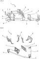
- FIGS. 3a and 3b show a seat unit 20, in particular for an aircraft cabin, comprising a seat 21, a privacy shell 22 which extends around the seat 21 so as to isolate the passenger from the outside environment, a console 23, an armrest 24, as well as a low seat structure 25 intended to ensure fixing of the assembly on rails 26 of the aircraft cabin.
- the seat 21 comprises a seat 28 and a reclining backrest 31.
- the seat 21 is preferably a "business" type seat movable between a sitting position and a bed position in which the various components of the seat 21 extend along a substantially horizontal plane.
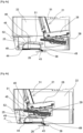
- a seat and backrest kinematics 29 visible on the Figures 4a and 4b comprises mechanical components enabling movement of the seat 28 and the backrest 31, in particular to move from the sitting position to the bed position, and vice versa.
- the console 23 has an upper face 32 on which the passenger can place objects, as shown in the Figures 3a and 3b .
- the console 23 may integrate a removable dining table 33, storage 34, as well as electrical outlets 35 for recharging electronic devices.
- the console 23 may also include an internal foot housing 36, clearly visible in figure 8b , intended to receive the feet of a rear passenger when the seat 21 of said rear passenger is in the bed position.
- the seat and backrest kinematics 29, the privacy shell 22, and the console 23 are mounted on the low seat structure 25, which is fixed to the rails 26 of the aircraft cabin by means of locks 38.
- electrical boxes 39 are positioned under the seat 21. These electrical boxes 39 are intended to supply, via a set of electrical harnesses 40, the various electrical components of the seat unit 20, such as actuators of the seat 21 or video screens of an entertainment system of the IFE type (for "Inflight Entertainment" in English).
- the low seat structure 25 comprises a chassis 41 with a tubular structure.
- chassis 41 is meant a chassis 41 formed by a plurality of hollow tubes.
- the tubular structure is a "mechanically welded” type structure, that is to say a structure formed by hollow metal tubes welded together.
- the metal tubes are made of steel.
- the tubes could however be made of another metal material, such as aluminum or magnesium, or any other material suitable for the application.
- the tubes preferably have a round or oval section particularly well suited to withstand torsional forces linked to the deformation of the floor of the aircraft cabin during a crash.
- the tubes could however have a rectangular, square, trapezoidal, triangular section or any other shape suitable for the application.
- the section may be constant along the length of the tubes or variable so as to locally reinforce the structure in areas subject to particularly significant mechanical constraints via welded or butted reinforcements or via deformation of the tube by a conification process ("butted tubing" in English).
- the tubular structure makes it possible to define independently the material thickness relative to the internal diameter of a tube to adapt the rigidity of the lower structure.
- the chassis 41 comprises a first lower tube 43 and a second lower tube 44.
- the first lower tube 43 and the second lower tube 44 each carry at least one lock 38 intended to be fixed on the rails 26 of the aircraft cabin.
- the chassis 41 further comprises two fixing feet 45 for the seat and backrest kinematics 29.
- a fixing foot 45 is formed by a tube connected by one of its ends to the first lower tube 43 of the chassis 41 and by its other end to the second lower tube 44 of the chassis 41.
- the fixing feet 45 extend projecting relative to a plane P in which the first lower tube 43 and the second lower tube 44 of the chassis 41 extend.
- a fixing foot 45 comprises an upper portion 48 and two connecting portions 49.
- a connecting portion 49 mechanically connects one end of the upper portion 48 to a corresponding lower tube 43, 44.
- the seat and backrest kinematics 29 are intended to be fixed on fixing guides 51.
- a fixing guide 51 is arranged on an upper portion 48 of a corresponding fixing foot 45 so as to be easily accessible to the operator.
- the fixing guides 51 also have an indexing function in order to facilitate the positioning of the seat and backrest kinematics 29 when mounting the seat 21.
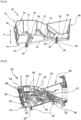
- the first lower tube 43 and the second lower tube 44 are bent such that a gap between the first lower tube 43 and the second lower tube 44 is variable when moving from one end of the tubes 43, 44 to the other, as illustrated by FIG. Figures 5 and 6 .
- the gap between the two lower tubes 43, 44 tends to decrease when moving from one end located on the side of the fixing feet 45 towards the opposite end.
- the lower seat structure 25 further comprises a reinforcing belt 52 formed by a plurality of tubes 53, 54.
- the plurality of tubes 53, 54 of the reinforcing belt 52 is mechanically connected to the lower tubes 43, 44.
- the reinforcing belt 52 is surrounded by a portion of the privacy shell 22. At least a portion of the privacy shell 22 is fixed to the reinforcing belt 52.
- the reinforcing belt 52 makes it possible to effectively absorb forces applied to the privacy shell 22 in the event of an impact. This improves the mechanical strength of the privacy shell 22 during a crash. Furthermore, due to a separate attachment of the shell 22 and the seat 21 to the low seat structure 25, such a configuration makes it possible to distribute and divide the paths of forces applied to the seat unit 20 during a crash.
- the reinforcing belt 52 comprises rising tubes 53 and a connecting tube 54 connecting the rising tubes 53 together.
- the rising tubes 53 are connected by one end to one of the lower tubes 43, 44 and by another end to the connecting tube 54.
- the connecting tube 54 extends in a substantially horizontal plane. Additional reinforcing tubes may be used to connect two adjacent rising tubes 53 together. Another configuration of tubes 53, 54 is of course conceivable.
- the reinforcing belt 52 extends vertically at a height of between 12 cm and 50 cm, and preferably of the order of 38 cm.
- By “of the order of” is meant a variation of plus or minus 10% around the target value.
- the privacy shell 22 is preferably made in two parts.
- the privacy shell 22 comprises a lower part 22.1 and an upper part 22.2, so that it is possible to dismantle only the lower part 22.1 to access the electrical boxes 39 located under the seat 21.
- the fixing of the privacy shell 22 on the reinforcement belt 52 may be carried out by means of sleeves 55 integral with the connecting tube 54.
- a fixing member such as a screw, is inserted inside a sleeve 55 so as to cooperate with a tapping made in an interface part of the shell 22.
- the screws may be replaced by rivets, studs, or any other fixing member adapted to the application.
- the reinforcing belt 52 may be extended by a tubular portion 56 to which the console 23 is fixed.
- the tubular portion 56 has a triangular shape corresponding to the shape of the console 23.
- the chute 57 for passing electrical harnesses 40 is fixed to the reinforcing belt 52, as shown in the figures 6 And 7 .
- the chute 57 preferably comprises removable fixing means 58 allowing the operator to easily fix the chute 57 on tubes 53, 54 of the reinforcement belt 52.
- the removable fixing means 58 may for example consist of elastically deformable snap-fastening devices, for example in the shape of a C.
- the electrical harnesses 40 coming from the electrical boxes 39 and intended to be connected to the various electrical components of the seat 21 can thus be arranged inside the chutes 57 in order to facilitate their installation in the lower part of the seat 21.
- the seat unit 20 preferably comprises three latches 38 so as to have a three-point attachment configuration. Alternatively, however, the seat unit 20 could comprise more than three latches 38.
- a lock 38 is associated with a lock support 59.
- the lock 38 is rotatably mounted about a horizontal axis relative to the lock support 59 to facilitate, via the presence of a degree of freedom in rotation, its installation on a corresponding rail 26.
- the pivot axis of the lock 38 extends in a longitudinal direction relative to the longitudinal axis of the aircraft.
- the lock support 59 may comprise a single opening 60 for the passage of a lower tube 43, 44 so as to allow movement of the lock support 59 along the lower tube 43, 44 before immobilization by welding of said lock support 59 in a position corresponding to positioning of a rail 26.
- the lock bracket 59 located on the right on the figure 5 comprises two openings 60, 60' for the passage respectively of the first lower tube 43 and the second lower tube 44 so as to allow movement of the lock support 59 along the lower tubes 43, 44 before immobilization by welding of said lock support 59 in a position corresponding to positioning of a rail 26.
- the pivot axis of the lock 38 extends in a transverse direction relative to the longitudinal axis of the aircraft.
- the lock support 59 is made in two parts.
- the lock support 59 is fixed to a corresponding lower tube 43, 44 by means of an axis 61 passing through a corresponding lower tube 43, 44.
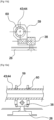
- a template 63 shown in the figure is used. figure 14 .
- the various tubes 43, 44, 53, 54 of the chassis 41 and of the reinforcing belt 52 are held in position by means of clamps 64 carried by columns 65 of the template 63.
- the lock supports 38 are moved along the lower tubes 43, 44 so as to cooperate with the corresponding rails 26 arranged at locations corresponding to a particular cabin configuration.
- a plate 66 makes it possible to define the distance between the fixing feet 45 of the seat 21.
- the lower seat structure 25 Once all the elements of the lower seat structure 25 are in a desired position, an operator or a robot can weld the tubes 43, 44, 53, 54 together as well as weld the lock supports 38 onto the lower tubes 43, 44. This produces the lower seat structure 25.
- the template 63 thus makes it possible to provide great modularity to the structure. seat base 25 which can easily adapt to the configuration of the aircraft cabin, the seat 21, the console 23, and the positioning of the rails 26.
- the lower seat structure 25 associated with the privacy shell 22 and the console 23 is first mounted on the rails 26 via the latches 38, as illustrated by the Figures 3a And 4a .
- the seat and backrest kinematics 29 are put in place on the fixing guides 51 which ensure the indexing in position of the seat and backrest kinematics 29.
- the seat and backrest kinematics 29 are fixed on the fixing guides 51 using suitable fixing means, such as screws or rivets.
- the seat 21 has an axis forming a non-zero angle relative to a longitudinal axis of the aircraft.
- the axis of the seat 21 may extend parallel to the longitudinal axis of the aircraft.
- the seat 21 may have several places. Alternatively, several seats 21 may be installed on the same low seat structure 25.
- the invention also relates to an aircraft comprising a plurality of seat units 20 as previously defined.
Landscapes
- Engineering & Computer Science (AREA)
- Aviation & Aerospace Engineering (AREA)
- Transportation (AREA)
- Mechanical Engineering (AREA)
- Seats For Vehicles (AREA)
Claims (14)
- Sitzeinheit (20), insbesondere für eine Flugzeugkabine, umfassend:- einem Sitz (21), der mit einer Sitzflächen- und Rückenlehnen-Kinematik (29) ausgestattet ist, und- eine untere Sitzstruktur (25), auf der der Sitz (21) montiert ist, wobei die untere Sitzstruktur (25) einen Rahmen (41) mit einer Rohrstruktur umfasst, die umfasst:- ein erstes Unterrohr (43) und ein zweites Unterrohr (44), wobei das erste Unterrohr (43) und das zweite Unterrohr (44) jeweils mindestens einen Riegel (38) zur Befestigung an Schienen (26) tragen, und- zwei Befestigungsfüßen (45) der Sitzflächen- und Rückenlehnen-Kinematik (29), wobei ein Befestigungsfuß (45) durch ein Rohr gebildet ist, das an einem seiner Enden mit dem ersten Unterrohr (43) des Rahmens (41) und an seinem anderen Ende mit dem zweiten Unterrohr (44) des Rahmens (41) verbunden ist,- wobei die Sitzeinheit außerdem eine Sichtschutzschale (22) aufweist,dadurch gekennzeichnet, dass die untere Sitzstruktur (25) außerdem einen Verstärkungsgurt (52) umfasst, der aus einer Mehrzahl von Rohren (53, 54) besteht, die mechanisch mit den unteren Rohren (43, 44) verbunden sind, wobei zumindest ein Abschnitt der Sichtschutzschale (22) an dem Verstärkungsgurt (52) befestigt ist.
- Sitzeinheit nach Anspruch 1, dadurch gekennzeichnet, dass die Befestigungsfüße (45) aus einer Ebene (P) herausragen, in der das erste Unterrohr (43) und das zweite Unterrohr (44) des Rahmens (41) verlaufen.
- Sitzeinheit nach Anspruch 1 oder 2, dadurch gekennzeichnet, dass eine Befestigungsführung (51) an einem oberen Abschnitt (48) eines entsprechenden Befestigungsfußes (45) angeordnet ist.
- Sitzeinheit nach einem der Ansprüche 1 bis 3, dadurch gekennzeichnet, dass das erste Unterrohr (43) und das zweite Unterrohr (44) derart gebogen sind, dass ein Spalt zwischen dem ersten Unterrohr (43) und dem zweiten Unterrohr (44) beim Bewegen von einem Ende der Rohre (43, 44) zum anderen veränderbar ist.
- Sitzeinheit nach einem der Ansprüche 1 bis 4, dadurch gekennzeichnet, dass der Verstärkungsgurt (52) von einem Abschnitt der Sichtschutzschale (22) umgeben ist.
- Sitzeinheit nach einem der Ansprüche 1 bis 5, dadurch gekennzeichnet, dass sich der Verstärkungsgurt (52) vertikal über eine Höhe (H) zwischen 12cm und 50cm, vorzugsweise in der Größenordnung von 38cm, erstreckt.
- Sitzeinheit nach einem der Ansprüche 1 bis 6, dadurch gekennzeichnet, dass die Sichtschutzschale (22) aus einem Unterteil (22.1) und einem Oberteil (22.2) besteht, so dass nur das Unterteil (22.1) abmontiert werden kann, um Zugang zu den Elektrokästen (39) unter dem Sitz (21) zu erhalten.
- Sitzeinheit nach einem der Ansprüche 1 bis 7, dadurch gekennzeichnet, dass an dem Verstärkungsgurt (52) mindestens eine Rutsche (57) zum Durchführen von elektrischen Kabelbäumen (40) befestigt ist.
- Sitzeinheit nach einem der Ansprüche 1 bis 8, dadurch gekennzeichnet, dass sie drei Riegel (38) umfasst, so dass eine Dreipunktbefestigungskonfiguration aufweist.
- Sitzeinheit nach einem der Ansprüche 1 bis 9, dadurch gekennzeichnet, dass einem Riegel (38) eine Riegelhalterung (59) zugeordnet ist.
- Sitzeinheit nach Anspruch 10, dadurch gekennzeichnet, dass die Riegelhalterung (59) eine einzige Öffnung (60) für den Durchgang eines unteren Rohrs (43, 44) aufweist, um eine Bewegung der Riegelhalterung (59) entlang des unteren Rohrs (43, 44) zu ermöglichen, bevor sie durch Schweißen in einer einer Positionierung einer Schiene (26) entsprechenden Position fixiert wird.
- Sitzeinheit nach Anspruch 10, dadurch gekennzeichnet, dass die Riegelhalterung (59) zwei Öffnungen (60, 604) für den Durchgang des ersten unteren Rohrs (43) bzw. des zweiten unteren Rohrs (44) aufweist, um eine Bewegung der Riegelhalterung (59) entlang der unteren Rohre (43, 44) zu ermöglichen, bevor sie durch Schweißen in einer einer Positionierung einer Schiene (26) entsprechenden Position fixiert wird.
- Sitzeinheit nach einem der Ansprüche 10 bis 12, dadurch gekennzeichnet, dass die Riegelhalterung (59) zweiteilig ausgebildet ist.
- Flugzeug mit einer Mehrzahl von Sitzeinheiten (20) gemäß einem der vorhergehenden Ansprüche.
Applications Claiming Priority (2)
| Application Number | Priority Date | Filing Date | Title |
|---|---|---|---|
| FR2007447A FR3112528B1 (fr) | 2020-07-16 | 2020-07-16 | Unite de siege munie d'une structure basse de siege de type tubulaire |
| PCT/EP2021/068885 WO2022013039A1 (fr) | 2020-07-16 | 2021-07-07 | Unite de siege munie d'une structure basse de siege de type tubulaire |
Publications (2)
| Publication Number | Publication Date |
|---|---|
| EP4182228A1 EP4182228A1 (de) | 2023-05-24 |
| EP4182228B1 true EP4182228B1 (de) | 2024-11-27 |
Family
ID=72885728
Family Applications (1)
| Application Number | Title | Priority Date | Filing Date |
|---|---|---|---|
| EP21739397.4A Active EP4182228B1 (de) | 2020-07-16 | 2021-07-07 | Sitzeinheit mit rohrförmiger sitzbasisstruktur |
Country Status (5)
| Country | Link |
|---|---|
| US (1) | US12208902B2 (de) |
| EP (1) | EP4182228B1 (de) |
| CN (1) | CN116194367A (de) |
| FR (1) | FR3112528B1 (de) |
| WO (1) | WO2022013039A1 (de) |
Families Citing this family (1)
| Publication number | Priority date | Publication date | Assignee | Title |
|---|---|---|---|---|
| US11365010B2 (en) * | 2018-10-31 | 2022-06-21 | Safran Seats Usa Llc | Bent tube seat structure |
Family Cites Families (23)
| Publication number | Priority date | Publication date | Assignee | Title |
|---|---|---|---|---|
| GB547453A (en) * | 1940-06-28 | 1942-08-27 | Warren Mcarthur | Improvement in chair construction |
| US3037812A (en) * | 1958-07-30 | 1962-06-05 | Benjamin F Monroe | Aircraft seat structure |
| ATE514593T1 (de) * | 2001-08-09 | 2011-07-15 | Virgin Atlantic Airways Ltd | Eine sitzeinheit für ein fahrzeug |
| US7533930B1 (en) * | 2007-10-24 | 2009-05-19 | Embraer - Empresa Brasileira De Aeronautica S.A. | Convertible aircraft passenger seat and method |
| WO2012073103A1 (en) * | 2010-12-01 | 2012-06-07 | Societe Industrielle Et Commerciale De Materiel Aeronautique | Aircraft seat |
| WO2013138542A2 (en) * | 2012-03-14 | 2013-09-19 | B/E Aerospace, Inc. | Armrest assembly with deployable bed extension |
| WO2013144935A2 (en) | 2012-07-06 | 2013-10-03 | Zodiac Seats France | Base frame assembly for passenger seats |
| US10266271B2 (en) * | 2014-03-28 | 2019-04-23 | B/E Aerospace, Inc. | Aircraft seat with segmented seatback for achieving in-bed lounge sitting position |
| WO2016031003A1 (ja) * | 2014-08-28 | 2016-03-03 | 株式会社ジャムコ | 航空機の乗客用シート |
| CN109311446B (zh) * | 2016-03-31 | 2021-10-22 | B/E航空公司 | 用于保护倾斜安装的飞机座椅中的乘客的系统和方法 |
| EP3519243B1 (de) * | 2016-09-28 | 2022-08-17 | Rockwell Collins, Inc. | Fluggastsitzanordnung mit einer neigevorrichtung für die rückenlehne |
| EP3595928B1 (de) * | 2017-03-17 | 2022-12-28 | Safran Seats USA LLC | Passagiersitz mit bewegbarer rückenlehnenteil |
| US20180281960A1 (en) * | 2017-04-03 | 2018-10-04 | Adient Engineering and IP GmbH | Airline seat and airline seatbelt system |
| WO2018184660A1 (en) * | 2017-04-03 | 2018-10-11 | Adient Us Llc | A seat for a vehicle |
| US10450072B2 (en) * | 2017-11-28 | 2019-10-22 | B/E Aerospace, Inc. | Seatback articulation assembly and method |
| US10683094B2 (en) * | 2017-12-11 | 2020-06-16 | Optimares S.P.A. | Aircraft seat |
| US11565819B2 (en) * | 2018-10-30 | 2023-01-31 | Rockwell Collins, Inc. | Dynamic electro-mechanical ottoman |
| US11365010B2 (en) * | 2018-10-31 | 2022-06-21 | Safran Seats Usa Llc | Bent tube seat structure |
| DE102019204488B4 (de) * | 2019-03-29 | 2023-05-04 | Adient Aerospace, Llc | Sitz, insbesondere Flugzeugsitz |
| US10870489B2 (en) * | 2019-05-24 | 2020-12-22 | B/E Aerospace, Inc. | Position adjustable armrest assemblies for passenger seats |
| FR3102753B1 (fr) | 2019-10-31 | 2022-05-06 | Safran Seats | Palette support pour une unite de siege d'avion |
| US11975845B2 (en) * | 2022-03-25 | 2024-05-07 | B/E Aerospace, Inc. | Passenger seat armrest recline mechanism |
| FR3135963B1 (fr) * | 2022-05-24 | 2024-10-04 | Airbus Atlantic Sas | Unité de siège pour passager d’aéronef avec position d’accueil |
-
2020
- 2020-07-16 FR FR2007447A patent/FR3112528B1/fr active Active
-
2021
- 2021-07-07 CN CN202180061190.6A patent/CN116194367A/zh active Pending
- 2021-07-07 WO PCT/EP2021/068885 patent/WO2022013039A1/fr not_active Ceased
- 2021-07-07 EP EP21739397.4A patent/EP4182228B1/de active Active
- 2021-07-07 US US18/015,523 patent/US12208902B2/en active Active
Also Published As
| Publication number | Publication date |
|---|---|
| US20230257124A1 (en) | 2023-08-17 |
| FR3112528B1 (fr) | 2022-08-12 |
| WO2022013039A1 (fr) | 2022-01-20 |
| FR3112528A1 (fr) | 2022-01-21 |
| US12208902B2 (en) | 2025-01-28 |
| EP4182228A1 (de) | 2023-05-24 |
| CN116194367A (zh) | 2023-05-30 |
Similar Documents
| Publication | Publication Date | Title |
|---|---|---|
| EP2007622B1 (de) | Luftfahrzeugboden, verwendung des bodens und mit dem boden ausgestatteter luftfahrzeugabschnitt | |
| EP1614624B1 (de) | Flugzeugdeck | |
| FR2733945A1 (fr) | Dispositif d'armature de dossier pour siege arriere de vehicule automobile, et siege comportant un tel dispositif | |
| FR3071442A1 (fr) | Systeme de sieges pour passager pour un moyen de transport | |
| EP4182228B1 (de) | Sitzeinheit mit rohrförmiger sitzbasisstruktur | |
| EP2678211B1 (de) | Anordnung zur anbringung einer lenksäule für ein motorfahrzeug | |
| FR3105167A1 (fr) | Portion de fuselage d’aéronef comportant des étais sous plancher déplaçables ou séparables | |
| EP4051590B1 (de) | Stützplatte für flugzeugsitzeinheit | |
| EP0747256B1 (de) | Drehbarer Sicherheitsitz | |
| EP4347400B1 (de) | Sitzschale, insbesondere für einen flugzeugsitz, mit einem beckenabstandsbereich | |
| EP4347399B1 (de) | Sitzschale, insbesondere für einen flugzeugsitz, mit einem rohr zur absorption kinetischer energie | |
| FR3133033A3 (fr) | Pièce d’interface pour armature d’assise d’ensemble de siège/s de véhicule, armature d’assise et ensemble de siège/s de véhicule | |
| FR2828451A1 (fr) | Systeme pour la fixation d'au moins un siege sur un plancher de vehicule, et plancher de vehicule equipe d'un tel systeme de fixation | |
| EP3795414B1 (de) | Gestell für sitzfläche eines sitzes für kraftfahrzeug | |
| EP3974294B1 (de) | Verfahren zum zusammenbau eines elektro- oder hybridfahrzeugs | |
| EP4527690B1 (de) | Karosserie für ein strassenfahrzeug zum transport von gütern mit einem spannsystem | |
| EP1726487B1 (de) | Gleitanordnung für einen Fahrzeuginnenraum | |
| EP3164294A1 (de) | Sitz für kraftfahrzeug und montageverfahren | |
| WO2024132490A1 (fr) | Accoudoir de siège muni d'une articulation à routage de câble optimisé | |
| FR3012385A1 (fr) | Siege escamotable anti deversement | |
| FR3155495A1 (fr) | Support de planche de bord. | |
| FR3042156A1 (fr) | Siege d’appoint pour vehicule de transport comportant un boitier de ceinture de securite escamotable | |
| FR3019501A1 (fr) | Siege de vehicule automobile | |
| FR3156083A1 (fr) | Dossier de siège de véhicule | |
| FR3143471A1 (fr) | Accoudoir de siège muni d'un dispositif de verrouillage et déverrouillage à configuration optimisée |
Legal Events
| Date | Code | Title | Description |
|---|---|---|---|
| STAA | Information on the status of an ep patent application or granted ep patent |
Free format text: STATUS: UNKNOWN |
|
| STAA | Information on the status of an ep patent application or granted ep patent |
Free format text: STATUS: THE INTERNATIONAL PUBLICATION HAS BEEN MADE |
|
| PUAI | Public reference made under article 153(3) epc to a published international application that has entered the european phase |
Free format text: ORIGINAL CODE: 0009012 |
|
| STAA | Information on the status of an ep patent application or granted ep patent |
Free format text: STATUS: REQUEST FOR EXAMINATION WAS MADE |
|
| 17P | Request for examination filed |
Effective date: 20230106 |
|
| AK | Designated contracting states |
Kind code of ref document: A1 Designated state(s): AL AT BE BG CH CY CZ DE DK EE ES FI FR GB GR HR HU IE IS IT LI LT LU LV MC MK MT NL NO PL PT RO RS SE SI SK SM TR |
|
| DAV | Request for validation of the european patent (deleted) | ||
| DAX | Request for extension of the european patent (deleted) | ||
| GRAP | Despatch of communication of intention to grant a patent |
Free format text: ORIGINAL CODE: EPIDOSNIGR1 |
|
| STAA | Information on the status of an ep patent application or granted ep patent |
Free format text: STATUS: GRANT OF PATENT IS INTENDED |
|
| INTG | Intention to grant announced |
Effective date: 20240809 |
|
| GRAS | Grant fee paid |
Free format text: ORIGINAL CODE: EPIDOSNIGR3 |
|
| GRAA | (expected) grant |
Free format text: ORIGINAL CODE: 0009210 |
|
| STAA | Information on the status of an ep patent application or granted ep patent |
Free format text: STATUS: THE PATENT HAS BEEN GRANTED |
|
| AK | Designated contracting states |
Kind code of ref document: B1 Designated state(s): AL AT BE BG CH CY CZ DE DK EE ES FI FR GB GR HR HU IE IS IT LI LT LU LV MC MK MT NL NO PL PT RO RS SE SI SK SM TR |
|
| REG | Reference to a national code |
Ref country code: GB Ref legal event code: FG4D Free format text: NOT ENGLISH |
|
| REG | Reference to a national code |
Ref country code: CH Ref legal event code: EP |
|
| REG | Reference to a national code |
Ref country code: IE Ref legal event code: FG4D Free format text: LANGUAGE OF EP DOCUMENT: FRENCH |
|
| REG | Reference to a national code |
Ref country code: DE Ref legal event code: R096 Ref document number: 602021022473 Country of ref document: DE |
|
| REG | Reference to a national code |
Ref country code: LT Ref legal event code: MG9D |
|
| REG | Reference to a national code |
Ref country code: NL Ref legal event code: MP Effective date: 20241127 |
|
| PG25 | Lapsed in a contracting state [announced via postgrant information from national office to epo] |
Ref country code: IS Free format text: LAPSE BECAUSE OF FAILURE TO SUBMIT A TRANSLATION OF THE DESCRIPTION OR TO PAY THE FEE WITHIN THE PRESCRIBED TIME-LIMIT Effective date: 20250327 Ref country code: HR Free format text: LAPSE BECAUSE OF FAILURE TO SUBMIT A TRANSLATION OF THE DESCRIPTION OR TO PAY THE FEE WITHIN THE PRESCRIBED TIME-LIMIT Effective date: 20241127 Ref country code: PT Free format text: LAPSE BECAUSE OF FAILURE TO SUBMIT A TRANSLATION OF THE DESCRIPTION OR TO PAY THE FEE WITHIN THE PRESCRIBED TIME-LIMIT Effective date: 20250327 |
|
| PG25 | Lapsed in a contracting state [announced via postgrant information from national office to epo] |
Ref country code: FI Free format text: LAPSE BECAUSE OF FAILURE TO SUBMIT A TRANSLATION OF THE DESCRIPTION OR TO PAY THE FEE WITHIN THE PRESCRIBED TIME-LIMIT Effective date: 20241127 Ref country code: NL Free format text: LAPSE BECAUSE OF FAILURE TO SUBMIT A TRANSLATION OF THE DESCRIPTION OR TO PAY THE FEE WITHIN THE PRESCRIBED TIME-LIMIT Effective date: 20241127 |
|
| REG | Reference to a national code |
Ref country code: AT Ref legal event code: MK05 Ref document number: 1745495 Country of ref document: AT Kind code of ref document: T Effective date: 20241127 |
|
| PG25 | Lapsed in a contracting state [announced via postgrant information from national office to epo] |
Ref country code: BG Free format text: LAPSE BECAUSE OF FAILURE TO SUBMIT A TRANSLATION OF THE DESCRIPTION OR TO PAY THE FEE WITHIN THE PRESCRIBED TIME-LIMIT Effective date: 20241127 |
|
| PG25 | Lapsed in a contracting state [announced via postgrant information from national office to epo] |
Ref country code: ES Free format text: LAPSE BECAUSE OF FAILURE TO SUBMIT A TRANSLATION OF THE DESCRIPTION OR TO PAY THE FEE WITHIN THE PRESCRIBED TIME-LIMIT Effective date: 20241127 |
|
| PG25 | Lapsed in a contracting state [announced via postgrant information from national office to epo] |
Ref country code: NO Free format text: LAPSE BECAUSE OF FAILURE TO SUBMIT A TRANSLATION OF THE DESCRIPTION OR TO PAY THE FEE WITHIN THE PRESCRIBED TIME-LIMIT Effective date: 20250227 |
|
| PG25 | Lapsed in a contracting state [announced via postgrant information from national office to epo] |
Ref country code: GR Free format text: LAPSE BECAUSE OF FAILURE TO SUBMIT A TRANSLATION OF THE DESCRIPTION OR TO PAY THE FEE WITHIN THE PRESCRIBED TIME-LIMIT Effective date: 20250228 Ref country code: AT Free format text: LAPSE BECAUSE OF FAILURE TO SUBMIT A TRANSLATION OF THE DESCRIPTION OR TO PAY THE FEE WITHIN THE PRESCRIBED TIME-LIMIT Effective date: 20241127 Ref country code: LV Free format text: LAPSE BECAUSE OF FAILURE TO SUBMIT A TRANSLATION OF THE DESCRIPTION OR TO PAY THE FEE WITHIN THE PRESCRIBED TIME-LIMIT Effective date: 20241127 |
|
| PG25 | Lapsed in a contracting state [announced via postgrant information from national office to epo] |
Ref country code: PL Free format text: LAPSE BECAUSE OF FAILURE TO SUBMIT A TRANSLATION OF THE DESCRIPTION OR TO PAY THE FEE WITHIN THE PRESCRIBED TIME-LIMIT Effective date: 20241127 |
|
| PG25 | Lapsed in a contracting state [announced via postgrant information from national office to epo] |
Ref country code: RS Free format text: LAPSE BECAUSE OF FAILURE TO SUBMIT A TRANSLATION OF THE DESCRIPTION OR TO PAY THE FEE WITHIN THE PRESCRIBED TIME-LIMIT Effective date: 20250227 |
|
| PG25 | Lapsed in a contracting state [announced via postgrant information from national office to epo] |
Ref country code: SM Free format text: LAPSE BECAUSE OF FAILURE TO SUBMIT A TRANSLATION OF THE DESCRIPTION OR TO PAY THE FEE WITHIN THE PRESCRIBED TIME-LIMIT Effective date: 20241127 |
|
| PG25 | Lapsed in a contracting state [announced via postgrant information from national office to epo] |
Ref country code: DK Free format text: LAPSE BECAUSE OF FAILURE TO SUBMIT A TRANSLATION OF THE DESCRIPTION OR TO PAY THE FEE WITHIN THE PRESCRIBED TIME-LIMIT Effective date: 20241127 |
|
| PG25 | Lapsed in a contracting state [announced via postgrant information from national office to epo] |
Ref country code: EE Free format text: LAPSE BECAUSE OF FAILURE TO SUBMIT A TRANSLATION OF THE DESCRIPTION OR TO PAY THE FEE WITHIN THE PRESCRIBED TIME-LIMIT Effective date: 20241127 |
|
| PG25 | Lapsed in a contracting state [announced via postgrant information from national office to epo] |
Ref country code: RO Free format text: LAPSE BECAUSE OF FAILURE TO SUBMIT A TRANSLATION OF THE DESCRIPTION OR TO PAY THE FEE WITHIN THE PRESCRIBED TIME-LIMIT Effective date: 20241127 |
|
| PG25 | Lapsed in a contracting state [announced via postgrant information from national office to epo] |
Ref country code: SK Free format text: LAPSE BECAUSE OF FAILURE TO SUBMIT A TRANSLATION OF THE DESCRIPTION OR TO PAY THE FEE WITHIN THE PRESCRIBED TIME-LIMIT Effective date: 20241127 |
|
| PG25 | Lapsed in a contracting state [announced via postgrant information from national office to epo] |
Ref country code: CZ Free format text: LAPSE BECAUSE OF FAILURE TO SUBMIT A TRANSLATION OF THE DESCRIPTION OR TO PAY THE FEE WITHIN THE PRESCRIBED TIME-LIMIT Effective date: 20241127 |
|
| PG25 | Lapsed in a contracting state [announced via postgrant information from national office to epo] |
Ref country code: IT Free format text: LAPSE BECAUSE OF FAILURE TO SUBMIT A TRANSLATION OF THE DESCRIPTION OR TO PAY THE FEE WITHIN THE PRESCRIBED TIME-LIMIT Effective date: 20241127 |
|
| REG | Reference to a national code |
Ref country code: DE Ref legal event code: R097 Ref document number: 602021022473 Country of ref document: DE |
|
| PG25 | Lapsed in a contracting state [announced via postgrant information from national office to epo] |
Ref country code: SE Free format text: LAPSE BECAUSE OF FAILURE TO SUBMIT A TRANSLATION OF THE DESCRIPTION OR TO PAY THE FEE WITHIN THE PRESCRIBED TIME-LIMIT Effective date: 20241127 |
|
| PLBE | No opposition filed within time limit |
Free format text: ORIGINAL CODE: 0009261 |
|
| STAA | Information on the status of an ep patent application or granted ep patent |
Free format text: STATUS: NO OPPOSITION FILED WITHIN TIME LIMIT |
|
| REG | Reference to a national code |
Ref country code: CH Ref legal event code: L10 Free format text: ST27 STATUS EVENT CODE: U-0-0-L10-L00 (AS PROVIDED BY THE NATIONAL OFFICE) Effective date: 20251008 |
|
| PGFP | Annual fee paid to national office [announced via postgrant information from national office to epo] |
Ref country code: DE Payment date: 20250722 Year of fee payment: 5 |
|
| PGFP | Annual fee paid to national office [announced via postgrant information from national office to epo] |
Ref country code: GB Payment date: 20250724 Year of fee payment: 5 |
|
| PGFP | Annual fee paid to national office [announced via postgrant information from national office to epo] |
Ref country code: FR Payment date: 20250722 Year of fee payment: 5 |
|
| 26N | No opposition filed |
Effective date: 20250828 |
|
| REG | Reference to a national code |
Ref country code: CH Ref legal event code: H13 Free format text: ST27 STATUS EVENT CODE: U-0-0-H10-H13 (AS PROVIDED BY THE NATIONAL OFFICE) Effective date: 20260224 |
|
| PG25 | Lapsed in a contracting state [announced via postgrant information from national office to epo] |
Ref country code: LU Free format text: LAPSE BECAUSE OF NON-PAYMENT OF DUE FEES Effective date: 20250707 |
|
| REG | Reference to a national code |
Ref country code: BE Ref legal event code: MM Effective date: 20250731 |
|
| PG25 | Lapsed in a contracting state [announced via postgrant information from national office to epo] |
Ref country code: BE Free format text: LAPSE BECAUSE OF NON-PAYMENT OF DUE FEES Effective date: 20250731 |