EP4178282A1 - Verfahren und vorrichtungen zum senden und empfangen eines synchronisationssignals und übertragungssystem - Google Patents
Verfahren und vorrichtungen zum senden und empfangen eines synchronisationssignals und übertragungssystem Download PDFInfo
- Publication number
- EP4178282A1 EP4178282A1 EP22209092.0A EP22209092A EP4178282A1 EP 4178282 A1 EP4178282 A1 EP 4178282A1 EP 22209092 A EP22209092 A EP 22209092A EP 4178282 A1 EP4178282 A1 EP 4178282A1
- Authority
- EP
- European Patent Office
- Prior art keywords
- synchronization signal
- system parameters
- terminal
- predetermined structure
- sets
- Prior art date
- Legal status (The legal status is an assumption and is not a legal conclusion. Google has not performed a legal analysis and makes no representation as to the accuracy of the status listed.)
- Granted
Links
Images


Classifications
-
- H—ELECTRICITY
- H04—ELECTRIC COMMUNICATION TECHNIQUE
- H04W—WIRELESS COMMUNICATION NETWORKS
- H04W56/00—Synchronisation arrangements
- H04W56/001—Synchronization between nodes
- H04W56/0015—Synchronization between nodes one node acting as a reference for the others
-
- H—ELECTRICITY
- H04—ELECTRIC COMMUNICATION TECHNIQUE
- H04L—TRANSMISSION OF DIGITAL INFORMATION, e.g. TELEGRAPHIC COMMUNICATION
- H04L27/00—Modulated-carrier systems
- H04L27/26—Systems using multi-frequency codes
-
- H—ELECTRICITY
- H04—ELECTRIC COMMUNICATION TECHNIQUE
- H04W—WIRELESS COMMUNICATION NETWORKS
- H04W56/00—Synchronisation arrangements
- H04W56/001—Synchronization between nodes
Definitions
- the disclosure relates to the field of communications, and in particular to methods and apparatuses for transmitting and receiving a synchronization signal and a transmission system.
- the coverage of the high frequency band is generally much smaller than the coverage of the low frequency band, and the smaller coverage generally results in a smaller delay spread of a channel.
- the corresponding coherent bandwidth in the high frequency band is larger than the coherent bandwidth in the low frequency band of 300MHz to 3000MHz, and the subcarrier width, after being increased relative to that in the LTE system, can still satisfy the design requirement that the subcarrier spacing is within the coherent bandwidth. Therefore, a subcarrier spacing (SCS) (equivalent to the subcarrier width) needs to be adjusted according to a frequency level of the carrier, and it is feasible and reasonable to perform the adjustment.
- SCS subcarrier spacing
- the new generation wireless NR system covers the carrier frequencies from sub 6G up to 100G, and needs to use different subcarrier spacings and other basic frame structure parameters to adapt to the carrier frequencies. That is, the frame structure design parameter on each carrier frequency will be different from one another. For example, the closer the frequency is to the core frequency of LTE, the closer the subcarrier spacing and other typical frame structure parameters are to the existing parameters of LTE, and the higher the frequency is, the larger the subcarrier spacing is.
- the subcarrier spacings under study may be 15 kHz, 30 kHz, 60 kHz, 75 kHz, 120 kHz, or up to 240 kHz, or may be less than 15 kHz.
- the ultrahigh reliable low delay communication (URLLC) service emphasizes low latency, and thus its corresponding symbol is shorter than that of enhanced Mobile Broadband (eMBB), and its subcarrier spacing is also larger than that of the eMBB.
- eMBB enhanced Mobile Broadband
- the mMTC service has demands of massive access and deep coverage, and thus its subcarrier spacing is much smaller than that of the eMBB service, and its symbol length is much larger than that of the eMBB.
- Multiple types of services are multiplexed on the same carrier, making the frame structure parameters of the system more complicated.
- the NR system When the NR system has multiple frame structure parameters at different carrier frequencies or even at the same carrier frequency, if the signals of the synchronization signals of the system has too many options as the frame structure parameters, it will bring high complexity to initial synchronization access of a terminal.
- the terminal has to try different synchronization signals for multiple times without any preset information, resulting in that the detection takes a long time and the detection success rate is low.
- Embodiments of the disclosure provides methods and apparatuses for transmitting and receiving a synchronization signal, and a transmission system, so as to at least solve the problem of excessive complexity in detection of the synchronization signal in the related technology.
- a method for transmitting a synchronization signal includes that, a base station determines one or more sets of system parameters, each set of the system parameters including at least one of the following information of a carrier: frequency information, or a frame structure parameter; the base station constructs a synchronization signal of a predetermined structure according to the system parameters; and the base station transmits the synchronization signal to a terminal.
- the one or more sets of system parameters correspond to the same predetermined structure.
- the predetermined structure includes at least one of the following characteristics: a sequence identification, a sequence length, a mapping manner in which a sequence is mapped to a resource, a mapping manner in which a modulation symbol generated by the sequence is mapped to the resource, a time domain position of the synchronization signal, or a frequency domain position of the synchronization signal.
- the frame structure parameter includes at least one of a subcarrier spacing, a cyclic prefix (CP) type, or a CP length.
- CP cyclic prefix
- the base station constructs a synchronization signal of a predetermined structure according to the system parameters includes that, the base station characterizes a time domain position and a frequency domain position by using a symbol number and a frequency domain subcarrier number respectively or using a physical resource position.
- the correspondence is determined by one of the following manners:
- the system parameters used by the common channel or signal are different from the system parameters used by the synchronization signal, the system parameters of the synchronization signal used by the common channel or signal are indicated through the synchronization signal in an explicit or implicit manner.
- the response information of the response information of the response information of the random access is used to indicate one of the following information of terminals other than the terminal: dedicated data, a control channel, a control signal, or a control parameter.
- the frame structure parameter includes at least one of a subcarrier spacing, a cyclic prefix (CP) type, or a CP length.
- CP cyclic prefix
- the operation that the terminal receives the synchronization signal as per a predetermined structure according to the system parameters includes that, the terminal receives the synchronization signal as per a first predetermined structure and when failing to receive and detect the synchronization signal, uses a second predetermined structure to receive the synchronization signal; or the terminal uses the second predetermined structure to receive the synchronization signal according to a terminal reception capability or a service type.
- the operation that the terminal acquires one or more sets of system parameters includes one of the following: the terminal acquires the one or more sets of system parameters through a mapping relationship between a predefined system parameter and a carrier frequency; the terminal acquires the one or more sets of system parameters through a mapping relationship between a system parameter indicated by signaling and the carrier frequency; or the terminal acquires the one or more sets of system parameters by performing blind detection on multiple sets of system parameters.
- the operation that the terminal acquires the synchronization signal as per a predetermined structure according to the system parameters includes that, the terminal characterizes a time domain position and a frequency domain position by using a symbol number and a frequency domain subcarrier number respectively, or the terminal characterizes the time domain position and the frequency domain position by directly using a physical resource, and receives the synchronization signal at the corresponding time domain position and frequency domain position.
- the predetermined structure includes at least one of the following characteristics: a sequence identification, a sequence length, a mapping manner in which a sequence is mapped to a resource, a mapping manner in which a modulation symbol generated by the sequence is mapped to the resource, a time domain position of the synchronization signal, or a frequency domain position of the synchronization signal.
- the frame structure parameter includes at least one of a subcarrier spacing, a cyclic prefix (CP) type, or a CP length.
- CP cyclic prefix
- the transmission module is further arranged to configure at least one of the following common channels or signals with part or all of the system parameters of the synchronization signal: broadcast information, common reference signal for reference signal received power (RSRP) measurement and beam calibration, response information of an access request, random access response information, response information of response information of the response information of the access request, response information of response information of response information of the random access, an uplink random access signal, an access request signal, response information of response information of the access request signal, or response information of response information of the uplink random access signal, and transmit the configured common channel or signal to the terminal.
- RSRP reference signal received power
- the system parameters used by the common channel or signal are different from the system parameters used by the synchronization signal, the system parameters of the synchronization signal used by the common channel or signal are indicated through the synchronization signal in an explicit or implicit manner.
- the predetermined structure includes a first predetermined structure and a second predetermined structure.
- Each of the first predetermined structure and the second predetermined structure is associated with at least one of the following: configuration of a carrier frequency, supported service types, or a terminal capability.
- an apparatus for receiving a synchronization signal comprising: an acquisition module, arranged to acquire one or more sets of system parameters, each set of the system parameters including at least one of the following information of a carrier: frequency information, or a frame structure parameter; a reception module, arranged to receive the synchronization signal as per a predetermined structure according to the system parameters.
- the one or more sets of system parameters correspond to the same predetermined structure.
- the frame structure parameter includes at least one of a subcarrier spacing, a cyclic prefix (CP) type, or a CP length.
- CP cyclic prefix
- the reception module is further arranged to: receive the synchronization signal as per a first predetermined structure according to the system parameters, and when failing to receive and detect the synchronization signal, use a second predetermined structure to receive the synchronization signal; or directly use the second predetermined structure to receive the synchronization signal according to capability of reception module.
- the acquisition module includes one of the following:
- the reception module is further arranged to characterize a time domain position and a frequency domain position by using a symbol number and a frequency domain subcarrier number respectively, or characterize the time domain position and the frequency domain position by directly using a physical resource, and receive the synchronization signal at the corresponding time domain position and frequency domain position.
- the reception module is arranged to receive at least one of the following common channels or signals with part or all of the system parameters which are as same as those of the synchronization signal: broadcast information, common reference signal for reference signal received power (RSRP) measurement and beam calibration, response information of an access request, random access response information, response information of response information of the response information of the access request, response information of response information of response information of the random access, an uplink random access signal, an access request signal, response information of response information of the access request signal, or response information of response information of the uplink random access signal.
- RSRP reference signal received power
- the terminal when the system parameters used by the common channel or signal are different from the system parameters used by the synchronization signal, the terminal indicates the system parameters of the synchronization signal used by the common channel or the signal in an explicit or implicit manner through the synchronization signal.
- a system for transmitting a synchronization signal including a base station and a terminal.
- the base station includes: a determination module, arranged to determine one or more sets of system parameters, each set of the system parameters including at least one of the following information of a carrier: frequency information, or a frame structure parameter; a construction module, arranged to construct a synchronization signal of a predetermined structure according to the system parameters; and a transmission module, arranged to transmit the synchronization signal to the terminal.
- the terminal includes: an acquisition module, arranged to acquire one or more sets of system parameters, each set of the system parameters including at least one of the following information of a carrier: frequency information, or a frame structure parameter; and a reception module, arranged to receive the synchronization signal as per a predetermined structure according to the system parameters.
- the one or more sets of system parameters correspond to the same predetermined structure.
- a storage medium is provided.
- the storage medium is arranged to store a program code for performing the following steps:
- the base station determines one or more sets of system parameters.
- Each set of system parameters includes at least one of a frequency information or a frame structure parameter.
- the base station constructs a synchronization signal of a predetermined structure according to the system parameters.
- the base station transmits a synchronization signal to the terminal, where one or more sets of system parameters correspond to the same predetermined structure.
- the base station determines one or more sets of system parameters for characterizing at least one of frequency information or a frame structure parameter of a carrier, constructs a synchronization signal of a predetermined structure according to the system parameters, and transmits the synchronization signal to the terminal, the one or more sets of system parameters correspond to the same predetermined structure. Since the synchronization signal of the predetermined structure, when being constructed, is determined according to at least one of the frequency information or the frame structure parameter of the carrier, the synchronization signals of the carriers are designed uniformly.
- the options for the synchronization signal to be accessed is limited to a reasonable range, which can solve the problem of excessive complexity in synchronization signal detection in the related technology, achieves the effect of reducing the detection complexity, improving the detection success rate, and reducing the detection latency.
- FIG. 1 is a flowchart of a method for transmitting a synchronization signal according to an embodiment of the present disclosure. As shown in FIG. 1 , the process includes the following steps.
- step S102 the base station determines one or more sets of system parameters.
- Each set of system parameters includes at least one of frequency information or a frame structure parameter of a carrier.
- step S104 the base station constructs a synchronization signal of a predetermined structure according to the system parameters.
- step S106 the base station transmits the synchronization signal to the terminal.
- the one or more sets of system parameters correspond to the same predetermined structure.
- the base station determines one or more sets of system parameters for characterizing at least one of frequency information or a frame structure parameter of a carrier, constructs a synchronization signal of a predetermined structure according to the system parameters, and transmits the synchronization signal to the terminal, the one or more sets of system parameters correspond to the same predetermined structure. Since the synchronization signal of the predetermined structure, when being constructed, is determined according to at least one of the frequency information or the frame structure parameter of the carrier, different system parameters can be system parameters in different parameter type sets, or system parameters in a same parameters type set but having different value assignments for the parameter type. Even if each set of system parameters is different from one other or there are multiple possible sets, the structures of the corresponding synchronization signals can be consistent.
- This method uniformly designs the synchronization signals of the carriers.
- the options for the synchronization signal to be accessed is limited to a reasonable range, for example, corresponding to a single predetermined structure, which can solve the problem of excessive complexity in synchronization signal detection in the related technology, achieves the effect of reducing the detection complexity, improving the detection success rate, and reducing the detection latency.
- the execution body of the foregoing steps may be a network side device, such as a base station, a transmission node, a relay station, etc., but is not limited thereto.
- the carrier frequency in this embodiment is the frequency information of the carrier.
- the frame structure parameter includes at least one of the following: a subcarrier spacing, a cyclic prefix (CP) type, and a CP length.
- the predetermined structure includes at least one of the following characteristics: a sequence identification, a sequence length, a mapping manner in which a sequence is mapped to a resource, a mapping manner in which a modulation symbol generated by the sequence is mapped to the resource, a time domain position of the synchronization signal, a frequency domain position of the synchronization signal, or etc..
- the advantage of the predetermined structure is that the constraints on the synchronization signal are based on a predefinition, which can effectively reduce the transmission and reception complexity of the synchronization signal.
- the predetermined structure may be classified into a logical structure and a physical structure.
- the time domain position and the frequency domain position of the synchronization signal in the logical structure are a logical time domain position and a logical frequency domain position respectively.
- the time domain position and the frequency domain position of the synchronization signal in the physical structure are a physical time domain position and a physical frequency domain position, respectively.
- the operation that the base station constructs the synchronization signal of the predetermined structure according to the system parameters includes that, the base station characterizes the logical time domain position and the logical frequency domain position using a symbol number and a frequency domain subcarrier number respectively, and maps the logical time domain position and the logical frequency domain position to a physical time domain position and a physical frequency domain position respectively.
- the frequency domain subcarrier is a smallest unit of the frequency domain resource, and multiple frequency domain subcarriers can be combined into a larger frequency domain resource unit. This larger frequency domain resource unit can also be used to characterize the frequency domain position.
- the operation that the base station constructs the synchronization signal of the predetermined structure according to the system parameters includes that, the base station constructs the synchronization signal by directly using the physical time domain position and the frequency domain position.
- the operation that the base station constructs the synchronization signal of the predetermined structure according to the system parameters includes the following two methods.
- the base station constructs a first synchronization signal of a same logic structure according to the multiple sets of different system parameters, and the multiple sets of different system parameters in the first synchronization signal have different physical structures;
- the base station constructs a second synchronization signal of a same physical structure according to the multiple sets of different system parameters, and the multiple sets of different system parameters in the second synchronization signal have different logical structures.
- the predetermined structure includes: a first predetermined structure and a second predetermined structure.
- the first predetermined structure and the second predetermined structure are all related to at least one of: configuration of a carrier frequency, supported service types, or a terminal capability.
- the base station may transmit the synchronization signal of the first predetermined structure and the second predetermined structure, or may transmit merely the synchronization signal of the first predetermined structure or merely the synchronization signal of the second predetermined structure.
- the one or more sets of system parameters correspond to the predetermined structure, and the frame structure parameters and the carrier frequencies have a one-to-one correspondence or a one-to-many correspondence.
- the correspondence is determined by one of the following manners: predefinition; signaling indication; obtaining by the terminal after performing blind detection on multiple system parameters.
- the operation that the base station transmits the synchronization signal to the terminal includes that, the base station configures at least one of the following common channels or signals with part or all of the system parameters of the synchronization signal: broadcast information, common reference signal for reference signal received power (RSRP) measurement and beam calibration, response information of an access request, random access response information, response information of response information of the response information of the access request, response information of response information of response information of the random access, an uplink random access signal, an access request signal, response information of response information of the access request signal, or response information of response information of the uplink random access signal, transmits the configured common channel or signal to the terminal.
- RSRP reference signal received power
- the response information of the response information of the response information of the random access may be used to indicate one of the following information of terminals other than the current terminal: dedicated data, a control channel, a control signal, a control parameter.
- dedicated data a control channel
- control signal a control parameter.
- the advantage of this method is that the terminal does not need to try system parameters of other common channels or signals after acquiring the synchronization signal information, which effectively reduces the system complexity.
- the system parameters of the synchronization signal include at least the frame structure parameter used by the synchronization signal.
- the terminal when the system parameters used by the common channel or signal are different from the system parameters used by the synchronization signal, the terminal indicates the system parameters of the synchronization signal used by the common channel or the signal in an explicit or implicit manner through the synchronization signal.
- FIG. 2 is a flowchart of a method for receiving a synchronization signal according to an embodiment of the present disclosure. As shown in FIG. 2 , the process includes the following steps.
- Step S202 the terminal acquires one or more sets of system parameters, each set of system parameters including at least one of frequency information or a frame structure parameter of a carrier.
- Step S204 the terminal receives the synchronization signal as per a predetermined structure according to the system parameters.
- the one or more sets of system parameters correspond to the same predetermined structure.
- the predetermined structure includes one of the following characteristics: a sequence identifier, a sequence length, a mapping manner in which a sequence is mapped to a resource, a mapping manner in which a modulation symbol generated by the sequence is mapped to the resource, a time domain position of the synchronization signal, and a frequency domain position of the synchronization signal.
- the frame structure parameter includes at least one of the following: a subcarrier spacing, a cyclic prefix (CP) type, and a CP length.
- CP cyclic prefix
- the operation that the terminal receiving the synchronization signal according to the predetermined parameter according to the system parameters includes the following actions.
- the terminal receives the synchronization signal according to a first predetermined structure.
- the terminal uses a second predetermined structure to receive the synchronization signal.
- the terminal may receive the synchronization signal by directly using the second predetermined structure according to the capability or the service type.
- the operation that the terminal acquires the one or more sets of system parameters including the following implementations.
- the terminal acquires the one or more sets of system parameters through a mapping relationship between a predefined system parameter and a carrier frequency;
- the operation that the terminal receives the synchronization signal of the predetermined structure according to the system parameters includes that, the terminal characterizes the time domain position and the frequency domain position by using the symbol number and the frequency domain subcarrier number respectively or characterizes the time domain position and the frequency domain position by directly using a physical resource, and receives synchronization signals at the corresponding time domain position and frequency domain position.
- the operations that the terminal receives the synchronization signal specifically includes that, the terminal receives at least one of the following common channels or signals with part or all of the system parameters which are as same as those of the synchronization signal: broadcast information, common reference signal for reference signal received power (RSRP) measurement and beam calibration, response information of an access request, random access response information, response information of response information of the response information of the access request, response information of response information of response information of the random access, an uplink random access signal, an access request signal, response information of response information of the access request signal, or response information of response information of the uplink random access signal.
- RSRP reference signal received power
- the terminal When the system parameters used by the common channel or signal are different from the system parameters used by the synchronization signal, the terminal indicates the system parameters of the synchronization signal used by the common channel or the signal in an explicit or implicit manner through the synchronization signal.
- the system parameters of the synchronization signal at least include the frame structure parameter.
- a synchronization signal transmission apparatus for transmitting a synchronization signal, an apparatus for receiving a synchronization signal, and a transmission system for the synchronization signal.
- the apparatuses are used to implement the above-described embodiments and preferred embodiments, and the description thereof has been omitted.
- the term "module” may implement a combination of software and/or hardware of a predetermined function.
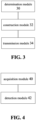
- FIG. 3 is a block diagram showing a structure of a device for transmitting a synchronization signal according to an embodiment of the present disclosure. As shown in FIG. 3 , the device includes a determination module 30, a construction module 32 and a transmission module 34.
- the determination module 30 is arranged to determine one or more sets of system parameters, each set of system parameters includes at least one of frequency information or a frame structure parameter.
- the construction module 32 is arranged to construct a synchronization signal of a predetermined structure according to system parameters.
- the transmission module 34 is arranged to transmit the synchronization signal to the terminal.
- the one or more sets of system parameters correspond to the same predetermined structure.
- the predetermined structure includes one of the following characteristics: a sequence identifier, a sequence length, a mapping manner in which a sequence is mapped to a resource, a mapping manner in which a modulation symbol generated by the sequence is mapped to the resource, a time domain position of the synchronization signal, and a frequency domain position of the synchronization signal.
- the frame structure parameter includes at least one of the following: a subcarrier spacing, a cyclic prefix (CP) type, and a CP length.
- the construction module further includes a construction unit, arranged to characterize the logical time domain position and the logical frequency domain position using a symbol number and a frequency domain subcarrier number respectively.
- the frequency domain subcarrier is a smallest unit of the frequency domain resource, and multiple frequency domain subcarriers can be combined into a larger frequency domain resource unit. This larger frequency domain resource unit can also be used to characterize the frequency domain position.
- the transmission modules is further arranged to configure at least one of the following common channels or signals with system parameters of the synchronization signal: broadcast information, common reference signal for reference signal received power (RSRP) measurement and beam calibration, response information of an access request, random access response information, response information of response information of the response information of the access request, response information of response information of response information of the random access, an uplink random access signal, an access request signal, response information of response information of the access request signal, or response information of response information of the uplink random access signal, transmit the configured common channel or signal to the terminal.
- RSRP reference signal received power
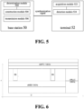
- FIG. 4 is a block diagram showing a structure of an apparatus for receiving a synchronization signal according to an embodiment of the present disclosure. As shown in FIG. 4 , the method includes an acquisition module 40 and a detection module 42.
- the acquisition module 40 is arranged to acquire one or more sets of system parameters.
- Each set of the system parameters includes at least one of frequency information or a frame structure parameter.
- the detection module 42 is arranged to receive the synchronization signal according to the predetermined configuration according to the system parameters by the terminal.
- the one or more sets of system parameters correspond to the same predetermined structure.
- the predetermined structure includes at least one of the following characteristics: a sequence identifier, a sequence length, a mapping manner in which a sequence is mapped to a resource, a mapping manner in which a modulation symbol generated by the sequence is mapped to the resource, a time domain position of the synchronization signal, and a frequency domain position of the synchronization signal.
- the frame structure parameter includes at least one of the following: a subcarrier spacing, a cyclic prefix (CP) type, and a CP length.
- CP cyclic prefix
- a reception module is arranged to receive the synchronization signal according to a first predetermined structure; when the synchronization signal is not received successfully, use a second predetermined structure to receive the synchronization signal.
- the reception module is further arranged to receive the synchronization signal by directly using the second predetermined structure according to the capability or the service type.
- the acquisition modules further includes at least one of the following units: a first acquisition unit, arranged to acquire the one or more sets of system parameters through a mapping relationship between a predefined system parameter and a carrier frequency; a second acquisition unit, arranged to acquire the one or more sets of system parameters through a mapping relationship between a system parameter indicated by the signaling and a carrier frequency; or a third acquisition unit, arranged to acquire the one or more sets of system parameters by performing blind detection on the multiple sets of system parameters.
- a first acquisition unit arranged to acquire the one or more sets of system parameters through a mapping relationship between a predefined system parameter and a carrier frequency
- a second acquisition unit arranged to acquire the one or more sets of system parameters through a mapping relationship between a system parameter indicated by the signaling and a carrier frequency
- a third acquisition unit arranged to acquire the one or more sets of system parameters by performing blind detection on the multiple sets of system parameters.
- the reception module is further arranged to characterize the time domain position and the frequency domain position by using the symbol number and the frequency domain subcarrier number respectively or by directly using a physical resource, and receive synchronization signals at the corresponding time domain position and frequency domain position.
- the frequency domain subcarrier is a smallest unit of the frequency domain resource, and multiple frequency domain subcarriers can be combined into a larger frequency domain resource unit. This larger frequency domain resource unit can also be used to characterize the frequency domain position.
- the reception module is further arranged to receive at least one of the following common channels or signals with the system parameters which are as same as those of the synchronization signal: broadcast information, common reference signal for reference signal received power (RSRP) measurement and beam calibration, response information of an access request, random access response information, response information of response information of the response information of the access request, response information of response information of response information of the random access, an uplink random access signal, an access request signal, response information of response information of the access request signal, or response information of response information of the uplink random access signal.
- RSRP reference signal received power
- the terminal when the system parameters used by the common channel or signal are different from the system parameters used by the synchronization signal, the terminal indicates the system parameters of the synchronization signal used by the common channel or the signal in an explicit or implicit manner through the synchronization signal.
- FIG. 5 is a block diagram showing a structure of a transmission system for a synchronization signal according to an embodiment of the present disclosure.
- the transmission system includes a base station 50 and a terminal 52.
- the base station 50 includes determination module 502, a construction module 504 and a transmission module 506.
- the determination module 502 is arranged to determine one or more sets of system parameters, each set of system parameters includes at least one of frequency information or a frame structure parameter of a carrier used by signal transmission between the base station and the terminal.
- the construction module 504 is arranged to construct a synchronization signal of a predetermined structure according to system parameters.
- the transmission module 506 is arranged to transmit the synchronization signal to the terminal.
- the terminal 52 includes an acquisition module 522 and a detection module 524.
- the acquisition module 522 is arranged to acquire one or more sets of system parameters.
- Each set of the system parameters includes at least one of frequency information or a frame structure parameter for characterizing the carrier.
- the detection module 524 is arranged to receive the synchronization signal according to the predetermined configuration according to the system parameters by the terminal.
- one or more sets of system parameters correspond to the same predetermined structure.
- each of the foregoing modules may be implemented by software or hardware.
- the foregoing modules may be, but not limited to, implemented in the following manner: the foregoing modules are all located in the same processor; or, the foregoing modules are located in different processors in any combination.
- This embodiment is an embodiment according to the present disclosure for explaining the subject matter in detail.
- One possible way is to decouple the design of the system parameters of the synchronization signal and the structure of the synchronization signal as much as possible to allow the various system parameters of the synchronization signals existing in the NR system to be mapped onto a basic structure of the synchronization signal or mapped to a very small number of special structures of the synchronization signal. Thus only the basic structure of synchronization signal or the special structures of the synchronization signal have to be detected.
- the corresponding structure of the synchronization signals can be consistent, thereby reducing the complexity in the detection process, achieving the purpose of ensuring the detection accuracy and reducing the detection latency.
- This embodiment includes the following two specific embodiments.
- the important parameters of frame structure parameters of the NR system are subcarrier spacing (SCS), symbol length, type and length of prefix CP, sampling frequency, points of Fast Fourier Transformation (FFT) etc., in which the subcarrier spacing is a core parameter, and the reciprocal of the subcarrier spacing is the symbol length (useful data portion, without prefix).
- SCS subcarrier spacing
- FFT Fast Fourier Transformation
- the URLLC, eMBB, and mMTC services use subcarrier spacings of 30KHz, 15KHz and 7.5KHz respectively and use the time-frequency resources of the NR system in the manner of FDM and TDM multiplexing.
- SS represents the synchronization signal.
- the system parameters of the SS are based on the subcarriers of the eMBB service, and also uses the subcarrier spacing of 15KHz. The practical solution is not limited to the illustrated manner.
- the system parameters of the synchronization signal include the above-mentioned frame structure parameters such as subcarrier spacing (SCS), symbol length, type and length of the prefix CP.
- the system parameters of the synchronization signal also include the frequency information of the carrier.
- the structure of the synchronization signal is a description of construction of a sequence of synchronization signals, a resource usage manner, and a resource mapping manner.
- the sequence design in the structure needs to consider the sequence type, sequence length, sequence identity, etc.
- the resource usage manner in the structure needs design of position of the logical or physical time-frequency resource used by the synchronization signal.
- the resource mapping manner in the structure needs design of a mapping manner in which the modulation symbols of the sequence of synchronization signals is mapped to the foregoing time-frequency resource, such as a center mapping, a continuous low-to-high mapping, and a comb-like mapping.
- the terminal When the terminal performs detection of reception of the synchronization signal, if the structure of the synchronization signal is uncertain, the main problem is that the terminal firstly has to find the time-frequency domain position of the synchronization signal, and has to determine the sequence identification, the possible length, a mapping manner in which sequence modulation symbols are mapped to logic and manner of physical resources, and other characteristics of the synchronization signal. Predetermined constraints on these characteristics can effectively reduce uncertainty and reduce the complexity of system transmission and terminal reception.
- the resources formed by the symbol position number and the frequency domain subcarrier position number are described as logical resources, then a same set of logic resources formed by unified symbol position numbers and frequency domain subcarrier position numbers can be used to be mapped to physical resources of different shapes under different subcarrier spacing parameters. Further, considering the sequence length and the mapping manner in which the modulation symbol is mapped to the logical resource, the same set of sequence design, such as sequence identification, sequence length, mapping manner of the sequence modulation symbol, etc., can be firstly mapped to logical resources, and then mapped to physical resources of different shapes under different subcarrier spacing parameters.
- the synchronization signal may have diversified system parameters, briefly speaking, various types of system parameters of the synchronization signal may correspond to a structure of the synchronization signal, and the absolute shapes of the physical resources under the same structure may be the same or different.
- FIG. 7 is a schematic diagram showing mapping of a same logical resource to physical resources of different shapes according to an embodiment of the present disclosure.
- FIG. 7 depicts that unified symbol position numbers and frequency domain subcarrier position numbers are used to be firstly mapped to logical resources, and then to physical resources of different shapes under different subcarrier spacing parameters.
- a and B are structures of two synchronizing signals having different shapes. However, since the parameters adopt a scalable manner, the actual areas of A and B are the same, that is, the time-frequency resource consumptions are the same. Both A and B are described using two symbols and six subcarriers.
- the frequency domain subcarrier is the smallest unit of the frequency domain resource, and multiple frequency domain subcarriers can be combined into a larger frequency domain resource unit. This larger frequency domain resource unit can also be used to represent the frequency domain position.
- the above solution represents different physical resources with a same logical resource, and finally achieve the purpose of corresponding the multiple system parameters of synchronization signals to a same structure.
- FIG. 8 is a schematic diagram showing mapping of different logical resources to a physical resource of a same shape according to an embodiment of the present disclosure, including two scenarios.
- the physical resources A and B are of a same shape, but have different basic parameters, e.g., subcarrier spacings.
- the subcarrier spacing of A is a half of that of B, and the symbol length of A is equal to the symbol length of B.
- the logical resource of A is 2 symbols and 6 subcarriers, and the logical resource ofB is 4 symbols and 3 subcarriers. This is also a way in which multiple system parameters of synchronization signals can correspond to a same structure.
- the multiple system parameters of the synchronization signals can correspond to the structure with a constant physical time resource.
- the structure of the synchronization signal corresponding to the system parameter of the 15KHz subcarrier spacing and that corresponding to the system parameter of the 30KHz subcarrier spacing may occupy the same physical time resource, or the structure of the synchronization signal corresponding to the system parameter of the 120KHz subcarrier spacing and that corresponding to the system parameter of the 240KHz subcarrier spacing may occupy the same physical time resource.
- the NR system at least needs to determine one basic structure for the synchronization signal.
- the basic and optional structures of the synchronization signal is related to the configuration of the carrier frequency, supported service types, and the terminal capability.
- the basic structure of the synchronization signal may be referred to as a first predetermined structure, and an optional structure of the synchronization signal may be referred to as a second predetermined structure.
- the first and second predetermined structures may appear in the same system, or only the first predetermined structure may appear in one system or only the second predetermined structure may appear in one system. Therefore, the "basic” and “optional” mentioned here does not mean that the “optional” must be based on the "basic”. The two are parallel and not mutually premised.
- the system parameters of the synchronization signal within the carrier may be the same as the parameters of a certain service (URLLC, eMBB or mMTC) on this carrier, or may be completely different.
- the system parameters, e.g., the subcarrier spacings, of the synchronization signal may be the same as the subcarrier spacing parameters of the eMBB service in the same carrier.
- the system parameters of the synchronization signal may be different from the parameters of all services in the carrier.
- the carrier frequency of a certain frequency band may have only one type of system parameters of the synchronization signal, or multiple frequency bands may share only one type of system parameters of the synchronization signal.
- the system parameters of the synchronization signal used by the system have to be known by the terminal to be detected.
- the terminal can learn the parameters used in the detection by the mapping relationship between the predefined system parameters and the carrier frequencies; or indicate the mapping relationship through signaling, and the signaling can be obtained through other carriers and other system-assisted methods, for example, the information of the system parameters of the NR can be acquired through the LTE system that is already accessed; or the terminal acquires accurate parameter information after blind detection of several possible types of system parameters of the synchronization signal.
- the system parameters of the synchronization signal can be similarly configured to other common channels and signals, such as broadcast information, common reference signal for RSRP measurement and beam calibration, response information of an access request, random access response information, response information of response information of the response information of the access request, response information of response information of response information of the random access, an uplink random access signal, an access request signal, response information of response information of the access request signal.
- the advantage of this operation is that the terminal does not need further search to confirm the system parameters of other common channels and signals after acquiring the synchronization information, thereby saving the implementation complexity of the terminal.
- FIG. 9 is a schematic diagram showing interaction of response information according to an embodiment of the present disclosure. As shown in FIG. 9 , the definitions of response information of random access, response information of response information of random access, and response information of response information of response information of random access are shown in FIG. 9 .
- the system parameters of the above signals and channels may be indicated in an explicit or implicit manner through the synchronization signal. By means of the indication, it is also possible to prevent the terminal from performing further blind detection of system parameters of the common channels and the signals.
- Parameters of other-terminal-specific data or control channels or signals may be indicated by response information of response information of response information of the random access.
- Embodiments of the present disclosure also provide a storage medium.
- the storage medium may be arranged to store a program code for performing the following steps:
- the storage medium may include, but is not limited to, various media such as a USB drive, a Read-Only Memory (ROM), a Random Access Memory (RAM), a mobile hard disk, and a magnetic disk or an optic disc, that can store the program code.
- various media such as a USB drive, a Read-Only Memory (ROM), a Random Access Memory (RAM), a mobile hard disk, and a magnetic disk or an optic disc, that can store the program code.
- the processor executes program codes stored in the storage medium to determine one or more sets of system parameters, each set of the system parameters includes at least one of the following information of a carrier: frequency information, or a frame structure parameter.
- the processor executes the program code stored in the storage medium to cause the base station to construct a synchronization signal of a predetermined structure according to the system parameters.
- the processor transmits a synchronization signal to the terminal according to the program code stored in the storage medium.
- One or more sets of system parameters correspond to the same predetermined structure.
- modules or steps of the present disclosure described above can be implemented by a general-purpose computing device, which can be centralized on a single computing device or distributed across a network of multiple computing devices. Alternatively, they may be implemented by program codes executable by the computing device such that they may be stored in the storage device to be executed by the computing device and, in some cases, may be different from the order illustrated or described herein.
- the steps shown or described are performed or fabricated separately into individual integrated circuit modules, or a plurality of modules or steps thereof are fabricated as a single integrated circuit module.
- the disclosure is not limited to any specific combination of hardware and software.
- the method and apparatus for transmitting and receiving a synchronization signal and the transmission system have the following beneficial effects: since the synchronization signal of the predetermined structure, when being constructed, is determined according to at least one of the frequency information or the frame structure parameter of the carrier, the synchronization signals of the carriers are designed uniformly. In the case of carriers of different frequencies, or in the case of multiple frame structure parameters in the same carrier, the options for the synchronization signal to be accessed is limited to a reasonable range, which can solve the problem of excessive complexity in synchronization signal detection in the related technology, achieves the effect of reducing the detection complexity, improving the detection success rate, and reducing the detection latency.
- the present disclosure also relates to the following items:
Landscapes
- Engineering & Computer Science (AREA)
- Computer Networks & Wireless Communication (AREA)
- Signal Processing (AREA)
- Mobile Radio Communication Systems (AREA)
- Quality & Reliability (AREA)
- Physics & Mathematics (AREA)
- Electromagnetism (AREA)
- Radar Systems Or Details Thereof (AREA)
Applications Claiming Priority (3)
| Application Number | Priority Date | Filing Date | Title |
|---|---|---|---|
| CN201610567463.5A CN107634924B (zh) | 2016-07-18 | 2016-07-18 | 同步信号的发送、接收方法及装置、传输系统 |
| PCT/CN2017/093393 WO2018014831A1 (zh) | 2016-07-18 | 2017-07-18 | 同步信号的发送、接收方法及装置、传输系统 |
| EP17830465.5A EP3487138B1 (de) | 2016-07-18 | 2017-07-18 | Verfahren und vorrichtung zum senden und empfangen von synchronen signalen und übertragungssystem |
Related Parent Applications (2)
| Application Number | Title | Priority Date | Filing Date |
|---|---|---|---|
| EP17830465.5A Division-Into EP3487138B1 (de) | 2016-07-18 | 2017-07-18 | Verfahren und vorrichtung zum senden und empfangen von synchronen signalen und übertragungssystem |
| EP17830465.5A Division EP3487138B1 (de) | 2016-07-18 | 2017-07-18 | Verfahren und vorrichtung zum senden und empfangen von synchronen signalen und übertragungssystem |
Publications (3)
| Publication Number | Publication Date |
|---|---|
| EP4178282A1 true EP4178282A1 (de) | 2023-05-10 |
| EP4178282B1 EP4178282B1 (de) | 2026-01-28 |
| EP4178282C0 EP4178282C0 (de) | 2026-01-28 |
Family
ID=60991948
Family Applications (2)
| Application Number | Title | Priority Date | Filing Date |
|---|---|---|---|
| EP17830465.5A Active EP3487138B1 (de) | 2016-07-18 | 2017-07-18 | Verfahren und vorrichtung zum senden und empfangen von synchronen signalen und übertragungssystem |
| EP22209092.0A Active EP4178282B1 (de) | 2016-07-18 | 2017-07-18 | Verfahren und vorrichtungen zum senden und empfangen eines synchronisationssignals und übertragungssystem |
Family Applications Before (1)
| Application Number | Title | Priority Date | Filing Date |
|---|---|---|---|
| EP17830465.5A Active EP3487138B1 (de) | 2016-07-18 | 2017-07-18 | Verfahren und vorrichtung zum senden und empfangen von synchronen signalen und übertragungssystem |
Country Status (7)
| Country | Link |
|---|---|
| US (2) | US11102737B2 (de) |
| EP (2) | EP3487138B1 (de) |
| CN (2) | CN107634924B (de) |
| ES (1) | ES2941064T3 (de) |
| FI (1) | FI3487138T3 (de) |
| PL (1) | PL3487138T3 (de) |
| WO (1) | WO2018014831A1 (de) |
Families Citing this family (16)
| Publication number | Priority date | Publication date | Assignee | Title |
|---|---|---|---|---|
| CN107634924B (zh) | 2016-07-18 | 2020-08-11 | 中兴通讯股份有限公司 | 同步信号的发送、接收方法及装置、传输系统 |
| CN107872415B (zh) * | 2016-09-23 | 2022-07-15 | 中兴通讯股份有限公司 | 一种数据传输方法及装置 |
| EP3739976B1 (de) * | 2018-02-09 | 2022-08-03 | Guangdong Oppo Mobile Telecommunications Corp., Ltd. | Verfahren und vorrichtung zur übertragung von synchronisierungssignalen und computerspeichermedium |
| CN110149642B (zh) | 2018-02-12 | 2021-12-10 | 华为技术有限公司 | 一种中继节点同步信号的发送方法及装置 |
| US11089558B2 (en) * | 2018-03-29 | 2021-08-10 | Qualcomm Incorporated | Resynchronization signal transmission in wireless communications |
| CN110768766B (zh) * | 2018-07-27 | 2021-04-20 | 华为技术有限公司 | 一种前导序列基带信号确定方法及装置 |
| CN110784293B (zh) * | 2018-07-31 | 2022-08-26 | 维沃移动通信有限公司 | 信号传输方法和通信设备 |
| WO2020151816A1 (en) * | 2019-01-23 | 2020-07-30 | Nokia Technologies Oy | Cooperative inter-network channel selection |
| US20220241428A1 (en) * | 2019-06-11 | 2022-08-04 | Myeloid Therapeutics, Inc. | Macrophage specific engager compositions and methods of use thereof |
| CN113133021B (zh) * | 2019-12-31 | 2025-06-17 | 中兴通讯股份有限公司 | 一种同步信号检测、传输方法、装置、设备和存储介质 |
| CN112235820B (zh) * | 2020-12-17 | 2021-03-12 | 京信通信系统(中国)有限公司 | 数据帧结构的配置方法、装置、计算机设备和存储介质 |
| CN113055914B (zh) * | 2021-03-26 | 2022-08-30 | 展讯通信(上海)有限公司 | 参考信号的测量方法、装置、设备及存储介质 |
| US11863359B1 (en) * | 2021-05-11 | 2024-01-02 | Amazon Technologies, Inc. | Subcarrier pre-equalization technology for frequency selective fading characteristics of wireless channels |
| JP7699207B2 (ja) * | 2021-05-31 | 2025-06-26 | 株式会社Nttドコモ | 無線通信ノード及び無線通信方法 |
| CN113691481B (zh) * | 2021-08-27 | 2024-11-26 | 深圳金信诺高新技术股份有限公司 | 一种新空口系统中帧同步的方法、装置、基站和存储介质 |
| CN114867040B (zh) * | 2022-04-28 | 2025-08-15 | 紫金山实验室 | 基站配置信息生成方法、装置 |
Citations (2)
| Publication number | Priority date | Publication date | Assignee | Title |
|---|---|---|---|---|
| CN101588337A (zh) * | 2008-05-22 | 2009-11-25 | 大唐移动通信设备有限公司 | 时分复用帧结构参数优化方法、通信方法、系统及终端 |
| US20160127098A1 (en) * | 2014-11-03 | 2016-05-05 | Samsung Electronics Co., Ltd. | Method and apparatus for channel access for lte on unlicensed spectrum |
Family Cites Families (147)
| Publication number | Priority date | Publication date | Assignee | Title |
|---|---|---|---|---|
| US6741868B1 (en) * | 1999-07-30 | 2004-05-25 | Curitell Communications Inc. | Method and apparatus for interfacing among mobile terminal, base station and core network in mobile telecommunications system |
| TWI260878B (en) * | 2004-08-13 | 2006-08-21 | Realtek Semiconductor Corp | Synchronization method and related apparatus of an OFDM digital communication system |
| CN1285194C (zh) * | 2004-11-01 | 2006-11-15 | 华为技术有限公司 | 一种实现多播业务资源指示的方法 |
| KR20060067505A (ko) * | 2004-12-15 | 2006-06-20 | 엘지노텔 주식회사 | 이더넷기반의 환경에서 다단 이더넷 스위치 구조의 클럭동기화 장치 및 방법 |
| JP4845582B2 (ja) * | 2006-05-09 | 2011-12-28 | 富士通株式会社 | 光伝送装置用プラグインカード |
| CN101940024A (zh) * | 2006-08-08 | 2011-01-05 | 北电网络有限公司 | 多种操作环境中的无线通信方法和系统 |
| WO2009019878A1 (ja) * | 2007-08-08 | 2009-02-12 | Panasonic Corporation | 無線送信装置及び無線通信方法 |
| US9119132B2 (en) * | 2007-10-10 | 2015-08-25 | Qualcomm Incorporated | Efficient system identification schemes for communication systems |
| CN101159483B (zh) * | 2007-10-28 | 2013-05-08 | 中兴通讯股份有限公司 | 一种时分双工系统信号的传输方法及其采用的帧结构 |
| WO2009061254A1 (en) * | 2007-11-06 | 2009-05-14 | Telefonaktiebolaget L M Ericsson (Publ) | Communications unit and method |
| KR101417089B1 (ko) * | 2008-01-03 | 2014-07-09 | 엘지전자 주식회사 | 무선통신 시스템에서 동기 신호 획득방법 |
| CN101465830B (zh) | 2007-12-19 | 2012-10-17 | 华为技术有限公司 | 发送、接收同步信息的方法与系统、装置 |
| US8265006B2 (en) * | 2007-12-31 | 2012-09-11 | Intel Corporation | Synchronization channel (preamble) structure for mobile worldwide interoperability for microwave access (WiMAX) systems |
| JP5122684B2 (ja) * | 2008-07-30 | 2013-01-16 | エルジー エレクトロニクス インコーポレイティド | 無線通信システムにおけるpdcchモニタリング方法及び装置 |
| US20100222062A1 (en) * | 2009-02-27 | 2010-09-02 | Industrial Technology Research Institute | Method, apparatus and system for interference avoidance in a femtocell network |
| WO2010107213A2 (ko) * | 2009-03-15 | 2010-09-23 | 엘지전자 주식회사 | 송/수신 시스템 및 방송 신호 처리 방법 |
| US8948064B2 (en) * | 2009-04-20 | 2015-02-03 | Full Spectrum Inc. | Method and apparatus for long range private broadband wireless communication system |
| US8923110B2 (en) * | 2009-04-24 | 2014-12-30 | Telefonaktiebolaget L M Ericsson (Publ) | Channel state information reconstruction from sparse data |
| US8638652B2 (en) * | 2009-05-29 | 2014-01-28 | Zte (Usa) Inc. | Signal transmission with fixed subcarrier spacing within OFDMA communication systems |
| CN102055701B (zh) * | 2009-10-29 | 2016-02-10 | 中兴通讯股份有限公司 | 一种同步信道的发送方法及相应的装置 |
| CN101702704A (zh) * | 2009-11-16 | 2010-05-05 | 清华大学 | 时域同步的多载波扩频收发方法、装置及系统 |
| KR101802754B1 (ko) * | 2010-01-17 | 2017-11-29 | 엘지전자 주식회사 | 무선 통신 시스템에서 제어 정보의 전송 방법 및 장치 |
| WO2012103946A1 (en) * | 2011-02-02 | 2012-08-09 | Fujitsu Limited | Wireless communication with co-operating cells |
| WO2012130073A1 (zh) * | 2011-03-25 | 2012-10-04 | 北京新岸线无线技术有限公司 | 用于无线通信的装置 |
| CN102223726A (zh) * | 2011-06-10 | 2011-10-19 | 中兴通讯股份有限公司 | 一种srs的发送方法和系统 |
| JP5240345B2 (ja) * | 2011-11-04 | 2013-07-17 | パナソニック株式会社 | 無線通信装置 |
| US9094977B2 (en) * | 2011-11-11 | 2015-07-28 | Samsung Electronics Co., Ltd. | Apparatus and method for supporting mobility management in communication systems with large number of antennas |
| US8953478B2 (en) * | 2012-01-27 | 2015-02-10 | Intel Corporation | Evolved node B and method for coherent coordinated multipoint transmission with per CSI-RS feedback |
| US9509458B2 (en) * | 2012-02-24 | 2016-11-29 | Lg Electronics Inc. | Transmission method and transmission device |
| JP5941305B2 (ja) * | 2012-03-14 | 2016-06-29 | シャープ株式会社 | 移動局装置、基地局装置、無線通信システム、無線通信方法および集積回路 |
| US9955442B2 (en) * | 2012-03-20 | 2018-04-24 | Qualcomm Incorporated | Synchronization channel design for new carrier type |
| US9078109B2 (en) * | 2012-04-09 | 2015-07-07 | Intel Corporation | Frame structure design for new carrier type (NCT) |
| CN103716841A (zh) * | 2012-09-29 | 2014-04-09 | 中兴通讯股份有限公司 | 信息传输方法及装置 |
| US9331786B2 (en) * | 2012-10-05 | 2016-05-03 | Futurewei Technologies, Inc. | Managing downstream non-broadcast transmission in an ethernet passive optical network (EPON) protocol over coax (EPoC) network |
| WO2014065563A1 (ko) * | 2012-10-22 | 2014-05-01 | 엘지전자 주식회사 | 사용자기기의 무선 프레임 설정 방법 및 사용자기기와, 기지국의 무선 프레임 설정 방법과 기지국 |
| US9743401B2 (en) * | 2012-10-22 | 2017-08-22 | Lg Electronics Inc. | Method, user equipment and base station for configuring radio frame for offsetting Doppler effect |
| CN104995855B (zh) * | 2013-01-17 | 2018-10-19 | 英特尔Ip公司 | 长期演进无线网络中的时分双工系统的信道状态信息参考信号模式 |
| CN105191195B (zh) * | 2013-01-21 | 2019-03-08 | 瑞典爱立信有限公司 | 用于使用动态传输参数的通信的方法和布置 |
| US9094835B2 (en) * | 2013-03-15 | 2015-07-28 | Intel Mobile Communications GmbH | Radio communication device and method for operating a radio communication device |
| JP6196373B2 (ja) | 2013-04-15 | 2017-09-13 | テレフオンアクチーボラゲット エルエム エリクソン(パブル) | Mtcデバイスへのシステム情報のシグナリング |
| KR101882953B1 (ko) * | 2013-04-18 | 2018-07-27 | 한국전자통신연구원 | 무선 프레임 구성 방법 및 이를 이용하는 장치 |
| WO2015001369A1 (en) * | 2013-07-01 | 2015-01-08 | Freescale Semiconductor, Inc. | Radio signal decoding and decoder |
| CN104349464B (zh) * | 2013-07-29 | 2018-05-15 | 中国移动通信集团公司 | 发送同步信号、确定载波类型的方法和设备 |
| US9591493B2 (en) * | 2013-08-19 | 2017-03-07 | Broadcom Corporation | Wireless communication fine timing measurement PHY parameter control and negotiation |
| US9258193B2 (en) * | 2014-01-14 | 2016-02-09 | Nokia Technologies Oy | Method, apparatus, and computer program product for wireless network cluster discovery and concurrency management |
| CN104812052B (zh) * | 2014-01-24 | 2020-01-10 | 中兴通讯股份有限公司 | D2d通信同步信号的传输方法及系统、发送端及接收端 |
| CN105981342A (zh) * | 2014-01-29 | 2016-09-28 | 诺基亚通信公司 | 部分sc-fdm符号的传输/接收 |
| US10862634B2 (en) * | 2014-03-07 | 2020-12-08 | Huawei Technologies Co., Ltd. | Systems and methods for OFDM with flexible sub-carrier spacing and symbol duration |
| JP2017513360A (ja) * | 2014-03-18 | 2017-05-25 | 華為技術有限公司Huawei Technologies Co.,Ltd. | ネットワークリスニング方法およびデバイス |
| WO2015156520A1 (ko) * | 2014-04-09 | 2015-10-15 | 엘지전자 주식회사 | 데이터 전송 방법 및 이를 이용한 장치 |
| WO2016004634A1 (en) * | 2014-07-11 | 2016-01-14 | Mediatek Singapore Pte. Ltd. | Method for enb, ue uplink transmission and reception |
| US9871568B2 (en) * | 2014-08-11 | 2018-01-16 | Intel Corporation | System detection in a high frequency band radio access technology architecture |
| CN105357162B (zh) * | 2014-08-22 | 2020-12-11 | 中兴通讯股份有限公司 | 一种信号处理方法、基站和终端 |
| CN104301273B (zh) * | 2014-08-25 | 2020-03-10 | 中兴通讯股份有限公司 | 使用非授权载波发送及接收信号的方法、基站及用户设备 |
| JPWO2016043019A1 (ja) * | 2014-09-19 | 2017-08-10 | シャープ株式会社 | 端末装置、基地局装置、および通信方法 |
| WO2016043018A1 (ja) * | 2014-09-19 | 2016-03-24 | シャープ株式会社 | 端末装置、基地局装置、および通信方法 |
| JP6555827B2 (ja) * | 2014-09-19 | 2019-08-07 | シャープ株式会社 | 通信装置、および通信方法 |
| CN110266371B (zh) * | 2014-09-23 | 2021-10-22 | 华为技术有限公司 | 发射器,接收器,和用于发送/接收同步信号的方法 |
| EP3018938B1 (de) * | 2014-11-07 | 2020-09-16 | Panasonic Intellectual Property Corporation of America | System für LTE-lizensierten, unterstützten Zugriff in unlizensierten Bändern |
| CN112217622B (zh) * | 2015-02-11 | 2024-09-20 | 苹果公司 | 使用统一的灵活5g空中接口的设备、系统和方法 |
| US10440671B2 (en) * | 2015-03-13 | 2019-10-08 | Sharp Kabushiki Kaisha | Terminal apparatus and communication method |
| KR102126323B1 (ko) * | 2015-03-28 | 2020-06-24 | 후아웨이 테크놀러지 컴퍼니 리미티드 | 무선 액세스 방법 및 장치, 통신 시스템, 그리고 단말 |
| US9985760B2 (en) * | 2015-03-31 | 2018-05-29 | Huawei Technologies Co., Ltd. | System and method for an adaptive frame structure with filtered OFDM |
| CN106161318B (zh) * | 2015-04-09 | 2019-07-05 | 中国移动通信集团公司 | 一种信号处理方法、发送机、接收机及系统 |
| WO2016182602A1 (en) * | 2015-05-08 | 2016-11-17 | Intel IP Corporation | Device and method of configurable synchronization signal and channel design |
| WO2016185747A1 (ja) * | 2015-05-20 | 2016-11-24 | ソニー株式会社 | 装置、方法、及びプログラム |
| AU2015396026B2 (en) * | 2015-05-27 | 2019-10-24 | Huawei Technologies Co., Ltd. | User equipment handover method, and device |
| US10693602B2 (en) * | 2015-05-29 | 2020-06-23 | Futurewei Technologies, Inc. | System and method for a long-term evolution (LTE)-compatible subframe structure for wideband LTE |
| US10038581B2 (en) * | 2015-06-01 | 2018-07-31 | Huawei Technologies Co., Ltd. | System and scheme of scalable OFDM numerology |
| EP3313136B1 (de) * | 2015-06-19 | 2020-08-19 | LG Electronics Inc. | Durch endgerät in einem drahtloskommunikationssystem durchgeführtes verfahren zur übertragung von v2x-nachrichten und endgerät mit verwendung davon |
| CN107787567B (zh) * | 2015-06-22 | 2020-11-10 | 瑞典爱立信有限公司 | 用于混合模式多载波调制的定时的控制 |
| US11012976B2 (en) * | 2015-07-02 | 2021-05-18 | Qualcomm Incorporated | Broadcast channel repetition |
| EP3320638A1 (de) * | 2015-07-06 | 2018-05-16 | Telefonaktiebolaget LM Ericsson (publ) | Ressourcenzuweisung für datenübertragungen in drahtlosen systemen |
| WO2017004774A1 (zh) | 2015-07-06 | 2017-01-12 | 华为技术有限公司 | 一种数据传输的方法、无线网络设备和通信系统 |
| US10855427B2 (en) * | 2015-07-24 | 2020-12-01 | Lg Electronics Inc. | Downlink signal reception method, user equipment, downlink signal transmission method and base station |
| KR102513274B1 (ko) * | 2015-08-21 | 2023-03-24 | 삼성전자주식회사 | 무선 통신 시스템에서 복합 재전송을 수행하는 방법 및 장치 |
| EP3342228A1 (de) * | 2015-08-25 | 2018-07-04 | IDAC Holdings, Inc. | Rahmen, planung und synchronisation in drahtlosen systemen |
| TWI763633B (zh) * | 2015-08-25 | 2022-05-11 | 美商Idac控股公司 | 無線傳輸/接收單元及在其中執行的方法 |
| USRE50308E1 (en) * | 2015-08-25 | 2025-02-18 | Nokia Solutions And Networks Oy | Radio frame configuration |
| EP4415432A3 (de) * | 2015-08-26 | 2024-10-09 | InterDigital Patent Holdings, Inc. | Systeme und verfahren zur leistungssteuerung in drahtlosen systemen |
| US9775045B2 (en) * | 2015-09-11 | 2017-09-26 | Intel IP Corporation | Slicing architecture for wireless communication |
| US10506626B2 (en) * | 2015-09-21 | 2019-12-10 | Lg Electronics Inc. | Method for receiving downlink control channel in wireless communication system and apparatus therefor |
| US10117199B2 (en) * | 2015-09-24 | 2018-10-30 | Lg Electronics Inc. | Method of transmitting channel state information and apparatus therefor |
| CN107925533B (zh) * | 2015-09-24 | 2022-06-17 | 苹果公司 | 高速环境中的v2x性能增强 |
| WO2017052320A1 (ko) * | 2015-09-25 | 2017-03-30 | 엘지전자 주식회사 | 무선 통신 시스템에서 상향링크 데이터를 전송하기 위한 방법 및 이를 위한 장치 |
| JP6137639B2 (ja) | 2015-09-28 | 2017-05-31 | 大日本印刷株式会社 | 柱状体を有する位相差制御板 |
| WO2017059127A1 (en) * | 2015-09-29 | 2017-04-06 | Newracom, Inc. | Resource allocation indication for multi-user multiple-input-multiple-output (mu-mimo) orthogonal frequency division multiple access (ofdma) communication |
| US10064217B2 (en) * | 2015-10-16 | 2018-08-28 | Samsung Electronics Co., Ltd. | Method and apparatus for enabling flexible numerology in multi-user MIMO system |
| US10524108B2 (en) * | 2015-10-19 | 2019-12-31 | Qualomm Incorporated | D2D communication for eMTC design considerations |
| US20170118055A1 (en) * | 2015-10-22 | 2017-04-27 | Mediatek Inc. | Flexible and Scalable Air Interface for Mobile Communication |
| US10181923B2 (en) * | 2015-10-30 | 2019-01-15 | Motorola Mobility Llc | Apparatus and method for generating and using a pilot signal |
| EP3375127B1 (de) * | 2015-11-13 | 2019-06-12 | Telefonaktiebolaget LM Ericsson (publ) | Ofdma-system mit gemischter numerologie für einen einzelnen dft-empfänger |
| US11102775B2 (en) * | 2015-11-26 | 2021-08-24 | Huawei Technologies Co., Ltd. | Resource block channelization for OFDM-based numerologies |
| US10225065B2 (en) * | 2015-12-18 | 2019-03-05 | Qualcomm Incorporated | Common control channel subband design and signaling |
| WO2017105005A1 (ko) * | 2015-12-18 | 2017-06-22 | 엘지전자 주식회사 | 랜덤 액세스 프리앰블을 싱글-톤 방식으로 전송하는 방법 및 무선 기기 |
| JP7118003B2 (ja) * | 2016-01-08 | 2022-08-15 | 華為技術有限公司 | スケジューリング方法、データ伝送方法及び装置 |
| EP3399817B1 (de) * | 2016-01-08 | 2025-09-03 | Huawei Technologies Co., Ltd. | Datenübertragungsverfahren und -vorrichtung |
| US11089579B2 (en) * | 2016-01-13 | 2021-08-10 | Samsung Electronics Co., Ltd. | Method and apparatus for supporting multiple services in advanced MIMO communication systems |
| US11070344B2 (en) * | 2016-01-13 | 2021-07-20 | Lg Electronics Inc. | Method and user equipment for receiving downlink channel, and method and base station for transmitting downlink channel |
| EP3393190B1 (de) | 2016-01-15 | 2022-02-23 | NTT DoCoMo, Inc. | Benutzerendgerät, drahtlosbasisstation und drahtloskommunikationsverfahren |
| US10405300B2 (en) * | 2016-02-04 | 2019-09-03 | Huawei Technologies Co., Ltd. | Signaling and control channel structures for multiple services |
| US10680871B2 (en) * | 2016-02-05 | 2020-06-09 | Huawei Technologies Co., Ltd. | Uplink subcarrier spacing indication method, base station, and terminal |
| HUE054905T2 (hu) * | 2016-02-05 | 2021-10-28 | Ericsson Telefon Ab L M | Rádiós erõforrás-kiosztás keskeny sávú kommunikációs rendszerben |
| US10594465B2 (en) * | 2016-02-22 | 2020-03-17 | Huawei Technologies Co., Ltd. | System and method for flexible channelization |
| US10716020B2 (en) * | 2016-02-23 | 2020-07-14 | Samsung Electronics Co., Ltd. | Method and apparatus for measurement reference signal |
| US10524237B2 (en) * | 2016-03-07 | 2019-12-31 | Samsung Electronics Co., Ltd. | Control signaling for supporting multiple services in advanced communication systems |
| US11457477B2 (en) * | 2016-03-29 | 2022-09-27 | Lg Electronics Inc. | Method for performing random access procedure in next generation wireless communication system and apparatus therefor |
| WO2017171398A1 (en) * | 2016-03-29 | 2017-10-05 | Lg Electronics Inc. | Method and apparatus for configuring frame structure for new radio access technology in wireless communication system |
| KR102198746B1 (ko) * | 2016-03-30 | 2021-01-06 | 아이디에이씨 홀딩스, 인크. | Lte(long term evolution) 지원형 nr플렉시블 무선 액세스 |
| WO2017179784A1 (ko) * | 2016-04-14 | 2017-10-19 | 엘지전자 주식회사 | 무선 통신 시스템에서 가변적 서브밴드 구성에 기반한 신호 송수신 방법 및 이를 위한 장치 |
| US10812238B2 (en) * | 2016-04-20 | 2020-10-20 | Convida Wireless, Llc | Configurable reference signals |
| JP2019517182A (ja) * | 2016-04-20 | 2019-06-20 | コンヴィーダ ワイヤレス, エルエルシー | ダウンリンク同期 |
| US10638474B2 (en) * | 2016-04-21 | 2020-04-28 | Qualcomm Incorporated | Different numerology for signal transmission |
| US10299283B2 (en) * | 2016-04-29 | 2019-05-21 | Huawei Technologies Co., Ltd. | System and method for coexistence of grant-free and grant-based uplink traffic |
| US10750513B2 (en) * | 2016-05-02 | 2020-08-18 | Lg Electronics Inc. | Signal transmission method performed by terminal in wireless communication system and terminal using same method |
| BR112018072666A2 (pt) * | 2016-05-04 | 2019-02-19 | Huawei Tech Co Ltd | método e aparelho de processamento de dados |
| US11764914B2 (en) * | 2016-05-09 | 2023-09-19 | Qualcomm Incorporated | Numerology dependent signal transmission |
| US10356800B2 (en) * | 2016-05-09 | 2019-07-16 | Qualcomm Incorporated | Scalable numerology with symbol boundary alignment for uniform and non-uniform symbol duration in wireless communication |
| US10660120B2 (en) * | 2016-05-11 | 2020-05-19 | Lg Electronics Inc. | Downlink signal reception method and user equipment, and downlink signal transmission method and base station |
| CN109588057B (zh) * | 2016-05-11 | 2021-09-07 | 康维达无线有限责任公司 | 一种经由通信电路连接到网络的方法和装置 |
| US10638473B2 (en) * | 2016-05-11 | 2020-04-28 | Idac Holdings, Inc. | Physical (PHY) layer solutions to support use of mixed numerologies in the same channel |
| CA3018597C (en) * | 2016-05-12 | 2024-05-28 | Guangdong Oppo Mobile Telecommunications Corp., Ltd. | System information transmission method, base station, and terminal |
| US10826736B2 (en) * | 2016-05-13 | 2020-11-03 | Nokia Solutions And Networks Oy | Reserving time alignment period for OFDMA communications with different numerology parameters |
| US20170332396A1 (en) * | 2016-05-13 | 2017-11-16 | Mediatek Inc. | Unified and Scalable Frame Structure for OFDM System |
| EP3466010B1 (de) * | 2016-05-22 | 2021-09-08 | LG Electronics Inc. | Verfahren und vorrichtung zur konfiguration einer rahmenstruktur für eine neue funkzugangstechnologie in einem drahtloskommunikationssystem |
| WO2017209585A1 (en) * | 2016-05-29 | 2017-12-07 | Lg Electronics Inc. | Method and apparatus for supporting mixed numerologies for urllc usage scenarios in wireless communication system |
| US10887035B2 (en) * | 2016-06-01 | 2021-01-05 | Qualcomm Incorporated | Time division multiplexing of synchronization channels |
| US11044072B2 (en) * | 2016-06-01 | 2021-06-22 | Qualcomm Incorporated | Optimized secondary synchronization signal |
| CN109219980B (zh) * | 2016-06-03 | 2020-06-02 | Oppo广东移动通信有限公司 | 传输数据的方法和装置 |
| US10715372B2 (en) * | 2016-06-07 | 2020-07-14 | Lg Electronics Inc. | Method for obtaining information about cyclic prefix in wireless communication system and device for same |
| WO2017213433A1 (en) * | 2016-06-08 | 2017-12-14 | Lg Electronics Inc. | A communication method using nr for 5g |
| US11012204B2 (en) * | 2016-06-08 | 2021-05-18 | Lg Electronics Inc. | Communication method of using full duplex in NR |
| US10880032B2 (en) * | 2016-06-12 | 2020-12-29 | Lg Electronics Inc. | Method for receiving signals and wireless device thereof |
| KR102397351B1 (ko) * | 2016-06-15 | 2022-05-13 | 콘비다 와이어리스, 엘엘씨 | 차세대 네트워크들에서의 랜덤 액세스 절차들 |
| JP6850308B2 (ja) * | 2016-06-15 | 2021-03-31 | コンヴィーダ ワイヤレス, エルエルシー | 新しい無線のためのアップロード制御シグナリング |
| US10448380B2 (en) * | 2016-06-27 | 2019-10-15 | Qualcomm Incorporated | Split symbol control for aligned numerology |
| WO2018004251A1 (ko) * | 2016-06-28 | 2018-01-04 | 엘지전자 주식회사 | 하향링크 신호 수신 방법 및 사용자기기와, 하향링크 신호 전송 방법 및 기지국 |
| WO2018008916A2 (ko) * | 2016-07-02 | 2018-01-11 | 엘지전자 주식회사 | 하향링크 신호 수신 방법 및 사용자기기와, 하향링크 신호 전송 방법 및 기지국 |
| WO2018009037A1 (en) * | 2016-07-07 | 2018-01-11 | Lg Electronics Inc. | Method and apparatus for signaling ue capability for new radio access technology in wireless communication system |
| EP3471481B1 (de) * | 2016-07-12 | 2021-08-11 | Guangdong Oppo Mobile Telecommunications Corp., Ltd. | Verfahren und endgerätevorrichtung zur übertragung von daten |
| WO2018012882A1 (en) * | 2016-07-12 | 2018-01-18 | Lg Electronics Inc. | Method and apparatus for performing mini-subframe based alignment for new radio access technology in wireless communication system |
| EP3934356B1 (de) * | 2016-07-12 | 2023-09-27 | Guangdong Oppo Mobile Telecommunications Corp., Ltd. | Datenübertragungsverfahren, endgerätevorrichtung und netzwerkvorrichtung |
| CN107634924B (zh) * | 2016-07-18 | 2020-08-11 | 中兴通讯股份有限公司 | 同步信号的发送、接收方法及装置、传输系统 |
| US10362610B2 (en) * | 2016-09-19 | 2019-07-23 | Samsung Electronics Co., Ltd. | Method and apparatus for mapping initial access signals in wireless systems |
| CN106507439B (zh) * | 2016-10-28 | 2019-12-10 | 宇龙计算机通信科技(深圳)有限公司 | 一种传输信息的方法、基站及终端 |
| US10356734B2 (en) * | 2016-11-30 | 2019-07-16 | Qualcomm Incorporated | Synchronization signal options for 5G/new radio |
| CN109391293B (zh) * | 2017-08-11 | 2022-01-14 | 华为技术有限公司 | 一种信号加扰、解扰方法及装置 |
-
2016
- 2016-07-18 CN CN201610567463.5A patent/CN107634924B/zh active Active
- 2016-07-18 CN CN202010801655.4A patent/CN111935814B/zh active Active
-
2017
- 2017-07-18 PL PL17830465.5T patent/PL3487138T3/pl unknown
- 2017-07-18 EP EP17830465.5A patent/EP3487138B1/de active Active
- 2017-07-18 EP EP22209092.0A patent/EP4178282B1/de active Active
- 2017-07-18 ES ES17830465T patent/ES2941064T3/es active Active
- 2017-07-18 FI FIEP17830465.5T patent/FI3487138T3/fi active
- 2017-07-18 WO PCT/CN2017/093393 patent/WO2018014831A1/zh not_active Ceased
-
2019
- 2019-01-18 US US16/252,539 patent/US11102737B2/en active Active
-
2021
- 2021-08-23 US US17/445,637 patent/US11910338B2/en active Active
Patent Citations (2)
| Publication number | Priority date | Publication date | Assignee | Title |
|---|---|---|---|---|
| CN101588337A (zh) * | 2008-05-22 | 2009-11-25 | 大唐移动通信设备有限公司 | 时分复用帧结构参数优化方法、通信方法、系统及终端 |
| US20160127098A1 (en) * | 2014-11-03 | 2016-05-05 | Samsung Electronics Co., Ltd. | Method and apparatus for channel access for lte on unlicensed spectrum |
Non-Patent Citations (1)
| Title |
|---|
| "EVOLVED PACKET SYSTEM (EPS) - THE LTE AND SAE EVOLUTION OF 3G UMTS", 11 January 2008, JOHN WILEY & SONS, LTD, Chichester, West Sussex, England ; Hoboken, NJ, ISBN: 978-0-470-05976-0, article PIERRE LESCUYER ET AL: "chapter 3: Physical Layer of E-UTRAN", pages: 158 - 159, XP055332210 * |
Also Published As
| Publication number | Publication date |
|---|---|
| WO2018014831A1 (zh) | 2018-01-25 |
| US11910338B2 (en) | 2024-02-20 |
| FI3487138T3 (fi) | 2023-05-22 |
| CN107634924B (zh) | 2020-08-11 |
| US20190215788A1 (en) | 2019-07-11 |
| EP3487138B1 (de) | 2023-03-15 |
| PL3487138T3 (pl) | 2023-09-11 |
| EP3487138A4 (de) | 2020-04-08 |
| CN107634924A (zh) | 2018-01-26 |
| EP4178282B1 (de) | 2026-01-28 |
| US11102737B2 (en) | 2021-08-24 |
| US20210385770A1 (en) | 2021-12-09 |
| CN111935814B (zh) | 2021-11-16 |
| EP4178282C0 (de) | 2026-01-28 |
| ES2941064T3 (es) | 2023-05-16 |
| EP3487138A1 (de) | 2019-05-22 |
| CN111935814A (zh) | 2020-11-13 |
Similar Documents
| Publication | Publication Date | Title |
|---|---|---|
| US11910338B2 (en) | Methods and apparatuses for transmitting and receiving synchronization signal, and transmission system | |
| US11516773B2 (en) | Methods and apparatus for supporting multiple services in wireless communication system | |
| US11265197B2 (en) | Synchronization signal block design | |
| AU2018200771B2 (en) | Systems and methods for ofdm with flexible sub-carrier spacing and symbol duration | |
| US11374706B2 (en) | Method and apparatus for transmitting and receiving a synchronization signal and transmission system | |
| US20170127365A1 (en) | System and method for transmitting a synchronization signal | |
| US12328217B2 (en) | Synchronization signal block transmitting and receiving method and device | |
| CN107733829B (zh) | 一种发送和检测同步信号的方法、设备 | |
| US20210367723A1 (en) | Method and device for wireless communication | |
| KR20180081549A (ko) | 네트워크 노드, 무선 디바이스, 방법들 및 컴퓨터 프로그램들 | |
| JP7068344B2 (ja) | 端末、無線通信方法、基地局及びシステム | |
| WO2014182230A1 (en) | Using a geometry indicator in hetnet deployments | |
| KR20200138386A (ko) | 클리어 채널 청취 방법, 장치 및 기기 | |
| US20250351124A1 (en) | Validating physical uplink shared channel (pusch) resource occasions | |
| US20260032666A1 (en) | Techniques for avoiding sounding reference signal and paging occasion collisions | |
| US20250350442A1 (en) | Techniques for resolving multiple collisions in sub-band full-duplex (sbfd) symbols | |
| WO2025015600A1 (en) | Guard band utilization for sidelink communications | |
| KR20250056065A (ko) | 자원을 할당하기 위한 장치 및 방법 | |
| CN120021325A (zh) | 波形确定方法、装置、通信设备及存储介质 | |
| CN120021326A (zh) | 波形确定方法、装置、通信设备及存储介质 | |
| CN112332961A (zh) | 资源映射、解资源映射的方法及其控制方法,以及相关装置 |
Legal Events
| Date | Code | Title | Description |
|---|---|---|---|
| PUAI | Public reference made under article 153(3) epc to a published international application that has entered the european phase |
Free format text: ORIGINAL CODE: 0009012 |
|
| STAA | Information on the status of an ep patent application or granted ep patent |
Free format text: STATUS: THE APPLICATION HAS BEEN PUBLISHED |
|
| AC | Divisional application: reference to earlier application |
Ref document number: 3487138 Country of ref document: EP Kind code of ref document: P |
|
| AK | Designated contracting states |
Kind code of ref document: A1 Designated state(s): AL AT BE BG CH CY CZ DE DK EE ES FI FR GB GR HR HU IE IS IT LI LT LU LV MC MK MT NL NO PL PT RO RS SE SI SK SM TR |
|
| STAA | Information on the status of an ep patent application or granted ep patent |
Free format text: STATUS: REQUEST FOR EXAMINATION WAS MADE |
|
| 17P | Request for examination filed |
Effective date: 20230628 |
|
| RBV | Designated contracting states (corrected) |
Designated state(s): AL AT BE BG CH CY CZ DE DK EE ES FI FR GB GR HR HU IE IS IT LI LT LU LV MC MK MT NL NO PL PT RO RS SE SI SK SM TR |
|
| GRAP | Despatch of communication of intention to grant a patent |
Free format text: ORIGINAL CODE: EPIDOSNIGR1 |
|
| STAA | Information on the status of an ep patent application or granted ep patent |
Free format text: STATUS: GRANT OF PATENT IS INTENDED |
|
| INTG | Intention to grant announced |
Effective date: 20251008 |
|
| GRAS | Grant fee paid |
Free format text: ORIGINAL CODE: EPIDOSNIGR3 |
|
| GRAA | (expected) grant |
Free format text: ORIGINAL CODE: 0009210 |
|
| STAA | Information on the status of an ep patent application or granted ep patent |
Free format text: STATUS: THE PATENT HAS BEEN GRANTED |
|
| AC | Divisional application: reference to earlier application |
Ref document number: 3487138 Country of ref document: EP Kind code of ref document: P |
|
| AK | Designated contracting states |
Kind code of ref document: B1 Designated state(s): AL AT BE BG CH CY CZ DE DK EE ES FI FR GB GR HR HU IE IS IT LI LT LU LV MC MK MT NL NO PL PT RO RS SE SI SK SM TR |
|
| REG | Reference to a national code |
Ref country code: CH Ref legal event code: F10 Free format text: ST27 STATUS EVENT CODE: U-0-0-F10-F00 (AS PROVIDED BY THE NATIONAL OFFICE) Effective date: 20260128 Ref country code: GB Ref legal event code: FG4D |
|
| REG | Reference to a national code |
Ref country code: DE Ref legal event code: R096 Ref document number: 602017093777 Country of ref document: DE |
|
| REG | Reference to a national code |
Ref country code: IE Ref legal event code: FG4D |
|
| U01 | Request for unitary effect filed |
Effective date: 20260128 |
|
| U07 | Unitary effect registered |
Designated state(s): AT BE BG DE DK EE FI FR IT LT LU LV MT NL PT RO SE SI Effective date: 20260205 |