EP4178068B1 - Ladevorrichtung - Google Patents
Ladevorrichtung Download PDFInfo
- Publication number
- EP4178068B1 EP4178068B1 EP22194252.7A EP22194252A EP4178068B1 EP 4178068 B1 EP4178068 B1 EP 4178068B1 EP 22194252 A EP22194252 A EP 22194252A EP 4178068 B1 EP4178068 B1 EP 4178068B1
- Authority
- EP
- European Patent Office
- Prior art keywords
- switch
- battery pack
- charging interface
- charging
- output module
- Prior art date
- Legal status (The legal status is an assumption and is not a legal conclusion. Google has not performed a legal analysis and makes no representation as to the accuracy of the status listed.)
- Active
Links
Images

Classifications
-
- H—ELECTRICITY
- H02—GENERATION; CONVERSION OR DISTRIBUTION OF ELECTRIC POWER
- H02J—ELECTRIC POWER NETWORKS; CIRCUIT ARRANGEMENTS OR SYSTEMS FOR SUPPLYING OR DISTRIBUTING ELECTRIC POWER; SYSTEMS FOR STORING ELECTRIC ENERGY
- H02J7/00—Circuit arrangements for charging or discharging batteries or for supplying loads from batteries
- H02J7/70—Circuit arrangements for charging or discharging batteries or for supplying loads from batteries characterised by the mechanical construction
- H02J7/751—Circuit arrangements for charging or discharging batteries or for supplying loads from batteries characterised by the mechanical construction concerning the insertion or the connection of the batteries
-
- H—ELECTRICITY
- H02—GENERATION; CONVERSION OR DISTRIBUTION OF ELECTRIC POWER
- H02J—ELECTRIC POWER NETWORKS; CIRCUIT ARRANGEMENTS OR SYSTEMS FOR SUPPLYING OR DISTRIBUTING ELECTRIC POWER; SYSTEMS FOR STORING ELECTRIC ENERGY
- H02J7/00—Circuit arrangements for charging or discharging batteries or for supplying loads from batteries
- H02J7/50—Circuit arrangements for charging or discharging batteries or for supplying loads from batteries acting upon multiple batteries simultaneously or sequentially
- H02J7/52—Circuit arrangements for charging or discharging batteries or for supplying loads from batteries acting upon multiple batteries simultaneously or sequentially for charge balancing, e.g. equalisation of charge between batteries
- H02J7/56—Active balancing, e.g. using capacitor-based, inductor-based or DC-DC converters
-
- H—ELECTRICITY
- H02—GENERATION; CONVERSION OR DISTRIBUTION OF ELECTRIC POWER
- H02J—ELECTRIC POWER NETWORKS; CIRCUIT ARRANGEMENTS OR SYSTEMS FOR SUPPLYING OR DISTRIBUTING ELECTRIC POWER; SYSTEMS FOR STORING ELECTRIC ENERGY
- H02J7/00—Circuit arrangements for charging or discharging batteries or for supplying loads from batteries
- H02J7/50—Circuit arrangements for charging or discharging batteries or for supplying loads from batteries acting upon multiple batteries simultaneously or sequentially
- H02J7/575—Parallel/serial switching of connection of batteries to charge or load circuit
-
- H—ELECTRICITY
- H01—ELECTRIC ELEMENTS
- H01M—PROCESSES OR MEANS, e.g. BATTERIES, FOR THE DIRECT CONVERSION OF CHEMICAL ENERGY INTO ELECTRICAL ENERGY
- H01M10/00—Secondary cells; Manufacture thereof
- H01M10/42—Methods or arrangements for servicing or maintenance of secondary cells or secondary half-cells
- H01M10/44—Methods for charging or discharging
- H01M10/441—Methods for charging or discharging for several batteries or cells simultaneously or sequentially
-
- H—ELECTRICITY
- H02—GENERATION; CONVERSION OR DISTRIBUTION OF ELECTRIC POWER
- H02J—ELECTRIC POWER NETWORKS; CIRCUIT ARRANGEMENTS OR SYSTEMS FOR SUPPLYING OR DISTRIBUTING ELECTRIC POWER; SYSTEMS FOR STORING ELECTRIC ENERGY
- H02J1/00—Circuit arrangements for DC mains or DC distribution networks
- H02J1/08—Three-wire DC power distribution systems; Systems having more than three wires
- H02J1/084—Three-wire DC power distribution systems; Systems having more than three wires for selectively connecting the load or loads to one or several among a plurality of power lines or power sources
-
- H—ELECTRICITY
- H02—GENERATION; CONVERSION OR DISTRIBUTION OF ELECTRIC POWER
- H02J—ELECTRIC POWER NETWORKS; CIRCUIT ARRANGEMENTS OR SYSTEMS FOR SUPPLYING OR DISTRIBUTING ELECTRIC POWER; SYSTEMS FOR STORING ELECTRIC ENERGY
- H02J1/00—Circuit arrangements for DC mains or DC distribution networks
- H02J1/10—Parallel operation of DC sources
- H02J1/109—Scheduling or re-scheduling the operation of the DC sources in a particular order, e.g. connecting or disconnecting the sources in sequential, alternating or in subsets, to meet a given demand
-
- H—ELECTRICITY
- H02—GENERATION; CONVERSION OR DISTRIBUTION OF ELECTRIC POWER
- H02J—ELECTRIC POWER NETWORKS; CIRCUIT ARRANGEMENTS OR SYSTEMS FOR SUPPLYING OR DISTRIBUTING ELECTRIC POWER; SYSTEMS FOR STORING ELECTRIC ENERGY
- H02J7/00—Circuit arrangements for charging or discharging batteries or for supplying loads from batteries
- H02J7/50—Circuit arrangements for charging or discharging batteries or for supplying loads from batteries acting upon multiple batteries simultaneously or sequentially
-
- H—ELECTRICITY
- H02—GENERATION; CONVERSION OR DISTRIBUTION OF ELECTRIC POWER
- H02J—ELECTRIC POWER NETWORKS; CIRCUIT ARRANGEMENTS OR SYSTEMS FOR SUPPLYING OR DISTRIBUTING ELECTRIC POWER; SYSTEMS FOR STORING ELECTRIC ENERGY
- H02J7/00—Circuit arrangements for charging or discharging batteries or for supplying loads from batteries
- H02J7/60—Circuit arrangements for charging or discharging batteries or for supplying loads from batteries including safety or protection arrangements
- H02J7/685—Circuit arrangements for charging or discharging batteries or for supplying loads from batteries including safety or protection arrangements using connection detecting circuits
-
- H—ELECTRICITY
- H02—GENERATION; CONVERSION OR DISTRIBUTION OF ELECTRIC POWER
- H02J—ELECTRIC POWER NETWORKS; CIRCUIT ARRANGEMENTS OR SYSTEMS FOR SUPPLYING OR DISTRIBUTING ELECTRIC POWER; SYSTEMS FOR STORING ELECTRIC ENERGY
- H02J7/00—Circuit arrangements for charging or discharging batteries or for supplying loads from batteries
- H02J7/80—Circuit arrangements for charging or discharging batteries or for supplying loads from batteries including monitoring or indicating arrangements
- H02J7/82—Control of state of charge [SOC]
-
- H—ELECTRICITY
- H02—GENERATION; CONVERSION OR DISTRIBUTION OF ELECTRIC POWER
- H02J—ELECTRIC POWER NETWORKS; CIRCUIT ARRANGEMENTS OR SYSTEMS FOR SUPPLYING OR DISTRIBUTING ELECTRIC POWER; SYSTEMS FOR STORING ELECTRIC ENERGY
- H02J7/00—Circuit arrangements for charging or discharging batteries or for supplying loads from batteries
- H02J7/90—Regulation of charging or discharging current or voltage
- H02J7/933—Regulation of charging or discharging current or voltage the cycle being controlled or terminated in response to electric parameters
-
- Y—GENERAL TAGGING OF NEW TECHNOLOGICAL DEVELOPMENTS; GENERAL TAGGING OF CROSS-SECTIONAL TECHNOLOGIES SPANNING OVER SEVERAL SECTIONS OF THE IPC; TECHNICAL SUBJECTS COVERED BY FORMER USPC CROSS-REFERENCE ART COLLECTIONS [XRACs] AND DIGESTS
- Y02—TECHNOLOGIES OR APPLICATIONS FOR MITIGATION OR ADAPTATION AGAINST CLIMATE CHANGE
- Y02T—CLIMATE CHANGE MITIGATION TECHNOLOGIES RELATED TO TRANSPORTATION
- Y02T10/00—Road transport of goods or passengers
- Y02T10/60—Other road transportation technologies with climate change mitigation effect
- Y02T10/70—Energy storage systems for electromobility, e.g. batteries
Definitions
- Examples of the present application relate to the field of battery pack charging technology and, in particular, to a charging device in the context of machine tools.
- a user generally uses a charger to charge a battery pack.
- Document EP3890135 A1 discloses a charging device with the technical features of the preamble of claim 1, for its use in battery energy storage systems (BESS) or solar energy systems and for electrical vehicle charging applications.
- BESS battery energy storage systems
- solar energy systems for electrical vehicle charging applications.
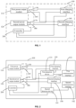
- a charging device includes a first power output module, a second power output module, a first charging interface, a second charging interface, and a controller.
- a first switch is coupled between the first power output module and the first charging interface.
- a second switch is coupled between the first power output module and the second charging interface.
- a third switch is coupled between the second power output module and the first charging interface.
- a fourth switch is coupled between the second power output module and the second charging interface.
- the controller is used for controlling the first switch, the second switch, the third switch and the fourth switch to be turned on or off.
- Two charging interfaces are provided in the charging device so that two battery packs can be charged, thereby improving the charging efficiency.
- the first switch is coupled between the first power output module and the first charging interface
- the second switch is coupled between the first power output module and the second charging interface
- the third switch is coupled between the second power output module and the first charging interface
- the fourth switch is coupled between the second power output module and the second charging interface
- the switches are controlled by the controller so that the charging device can control the switches to be turned on or off according to an actual application situation, thereby improving the charging efficiency and achieving high flexibility.
- a charging device 100 includes a first power output module 110, a second power output module 120, a first charging interface 130, a second charging interface 140, and a controller 200.
- the charging device 100 refers to a device for charging a battery pack of a power tool.
- the power tool may include, but is not limited to, a string trimmer, a blower, a pruner, a chainsaw, a lawn mower, an angle grinder, and an electric drill.
- the power tool may also include another type of tool, which is not limited in the examples of the present application.
- the battery pack includes a housing, the housing at least partially forms an outer surface of the battery pack and is used for accommodating at least a cell group, and the cell group includes multiple cells which are electrically connected to form the cell group.
- the housing is further formed with a plugging interface for connecting the battery pack to the power tool, and the battery pack can be connected to the power tool along a plugging direction.
- the battery pack may be used for supplying power to the power tool.
- the charging device 100 may be a charger or an adapter, which is not limited in the examples of the present application.
- a first switch 150 is coupled between the first power output module 110 and the first charging interface 130.
- the first power output module 110 refers to a module outputting power
- the first charging interface 130 refers to an interface for supplying power of the charging device 100 to the battery pack of the power tool. In the case where the first switch 150 is on, the first power output module 110 supplies power to the first charging interface 130; and in the case where the first switch 150 is off, the first power output module 110 does not supply power to the first charging interface 130.
- a second switch 160 is coupled between the first power output module 110 and the second charging interface 140.
- the second charging interface 140 refers to an interface for supplying the power of the charging device 100 to the battery pack of the power tool. In the case where the second switch 160 is on, the first power output module 110 supplies power to the second charging interface 140; and in the case where the second switch 160 is off, the first power output module 110 does not supply power to the second charging interface 140.
- the first switch 150 and the second switch 160 are single pole, single throw switches, that is, an end of the first switch 150 is coupled to the first power output module 110 and the other end of the first switch 150 is coupled to the first charging interface 130.
- An end of the second switch 160 is coupled to the first power output module 110 and the other end of the second switch 160 is coupled to the second charging interface 140.
- the first switch and the second switch may be provided as one switch, where the switch may be used for making the first power output module supply power to the first charging interface or making the first power output module supply power to the second charging interface or making the first power output module not supply power to the first charging interface and the second charging interface.
- the switch may be a single pole, triple throw switch, or the switch may be a two-way metal-oxide-semiconductor field-effect transistor (MOSFET) switch, or the switch may be a two-way single pole, double throw switch.
- MOSFET metal-oxide-semiconductor field-effect transistor
- the type of the switch is not limited in the examples of the present application, and the switch may be replaced with any type of switch capable of implementing the preceding functions.
- a third switch 170 is coupled between the second power output module 120 and the first charging interface 130.
- the second power output module 120 refers to a module outputting power.
- the power outputted by the first power output module 110 may or may not be consistent with the power outputted by the second power output module 120, which may be set by a technician according to actual requirements.
- the third switch 170 In the case where the third switch 170 is on, the second power output module 120 supplies power to the first charging interface 130; and in the case where the third switch 170 is off, the second power output module 120 does not supply power to the first charging interface 130.
- a fourth switch 180 is coupled between the second power output module 120 and the second charging interface 140. In the case where the fourth switch 180 is on, the second power output module 120 supplies power to the second charging interface 140; and in the case where the fourth switch 180 is off, the second power output module 120 does not supply power to the second charging interface 140.
- the third switch 170 and the fourth switch 180 are single pole, single throw switches, that is, an end of the third switch 170 is coupled to the second power output module 120 and the other end of the third switch 170 is coupled to the first charging interface 130; and an end of the fourth switch 180 is coupled to the second power output module 120 and the other end of the fourth switch 180 is coupled to the second charging interface 140.
- the third switch and the fourth switch may be provided as one switch, where the switch may be used for making the second power output module supply power to the first charging interface or making the second power output module supply power to the second charging interface or making the second power output module not supply power to the first charging interface and the second charging interface.
- the switch may be a single pole, triple throw switch, or the switch may be a two-way MOSFET switch, or the switch may be a two-way single pole, double throw switch.
- the type of the switch is not limited in the examples of the present application, and the switch may be replaced with any type of switch capable of implementing the preceding functions.
- FIG. 2 is a schematic diagram of switches according to an example of the present application. In FIG. 2 , the charging device 100 uses single pole, triple throw switches.
- the controller 200 is used for controlling the first switch 150, the second switch 160, the third switch 170 and the fourth switch 180 to be turned on or off.
- the controller 200 acquires a load state of the first charging interface 130 and a load state of the second charging interface 140 and controls the first switch 150, the second switch 160, the third switch 170 and the fourth switch 180 to be turned on or off, where the load state of the first charging interface 130 is used for indicating whether the first charging interface 130 is connected to a first battery pack.
- the load state of the first charging interface 130 is also used for indicating a state of charge of the first battery pack when the first charging interface 130 is connected to the first battery pack
- the load state of the second charging interface 140 is used for indicating whether the second charging interface 140 is connected to a second battery pack and a state of charge of the second battery pack.
- the controller 200 controls, according to the load state of the first charging interface 130 and the load state of the second charging interface 140, the first switch, the second switch, the third switch and the fourth switch to be turned on or off so that the power supply output of the charging device 100 to the battery pack is more in line with the charging requirements of the battery pack, thereby improving the charging efficiency of the charging device 100.
- the charging device 100 includes the first charging interface 130 and the second charging interface 140, the first switch 150 is coupled between the first power output module 110 and the first charging interface 130, the second switch 160 is coupled between the first power output module 110 and the second charging interface 140, the third switch 170 is coupled between the second power output module 120 and the first charging interface 130, the fourth switch 180 is coupled between the second power output module 120 and the second charging interface 140, and the switches are controlled by the controller 200. In this manner, the output capacity and parallel function of the charging device 100 are increased so that the battery pack can be charged fast at high power.
- two charging interfaces are provided in the charging device 100 so that two battery packs can be charged at the same time, thereby improving the charging efficiency.
- first switch 150 is coupled between the first power output module 110 and the first charging interface 130
- second switch 160 is coupled between the first power output module 110 and the second charging interface 140
- third switch 170 is coupled between the second power output module 120 and the first charging interface 130
- fourth switch 180 is coupled between the second power output module 120 and the second charging interface 140
- the switches are controlled by the controller 200 so that the charging device 100 can control the switches to be turned on or off according to an actual application situation, thereby improving the charging efficiency and achieving high flexibility.
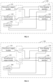
- the charging device 100 further includes a first detection device 131 and a second detection device 141.
- the first detection device 131 is used for determining the load state of the first charging interface 130, where the load state of the first charging interface 130 is used for indicating whether the first charging interface 130 is connected to the first battery pack and the state of charge of the first battery pack.
- the state of charge of the first battery pack is used for indicating the current charge of the first battery pack.
- the first detection device 131 is coupled to the first charging interface 130.
- the first detection device 131 may determine whether the first charging interface 130 is connected to the first battery pack by detecting whether a voltage exists across the first charging interface 130. In a possible example, to more accurately detect whether the first charging interface 130 is connected to the first battery pack, and the first detection device 131 is also coupled to a first communication interface 132 on the charging device 100.
- the first detection device 131 determines a voltage across the first charging interface and a voltage across the first communication interface 132 at the same time and determines. Based on the voltage across the first charging interface 130 and the voltage across the first communication interface 132, determine whether the first charging interface 130 is connected to the first battery pack.
- the first detection device 131 determines that the first charging interface 130 is connected to the first battery pack. In the case where the first detection device 131 determines that no voltage exists across the first charging interface 130 and no voltage exists across the first communication interface 132, the first detection device 131 determines that the first charging interface 130 is not connected to the first battery pack. In the case where the first detection device 131 determines that a voltage exists across the first charging interface 130 and no voltage exists across the first communication interface 132, the first detection device 131 determines that the first charging interface 130 is not connected to the first battery pack.
- the first detection device 131 determines that no voltage exists across the first charging interface 130 and a voltage exists across the first communication interface 132, the first detection device 131 determines that the first charging interface 130 is not connected to the first battery pack.
- the first charging interface 130 includes a positive interface and a negative interface
- the first battery pack includes a positive terminal and a negative terminal.
- the first communication interface 132 is used for the charging device 100 to communicate with the first battery pack.
- the first battery pack further includes a communication port. When the first communication interface 132 of the charging device 100 is coupled to the communication port of the first battery pack, the first battery pack may communicate with the charging device 100.
- the first battery pack sends its state of charge to the charging device 100 through the communication port.
- the charging device 100 automatically detects the charge of the first battery pack to obtain the state of charge of the first battery pack.
- the second detection device 141 is used for determining the load state of the second charging interface 140, where the load state of the second charging interface 140 is used for indicating whether the second charging interface 140 is connected to the second battery pack and the state of charge of the second battery pack.
- the state of charge of the second battery pack is used for indicating the current charge of the second battery pack.
- the second detection device 141 is coupled to the second charging interface 140.
- the second detection device 141 may determine whether the second charging interface 140 is connected to the second battery pack by detecting whether a voltage exists across the second charging interface 140.
- the second detection device 141 is also coupled to a second communication interface 142 on the charging device 100, and the second detection device 141 determines a voltage across the second charging interface 140 and a voltage across the second communication interface 142 at the same time and determines, based on the voltage across the second charging interface 140 and the voltage across the second communication interface 142, whether the second charging interface 140 is connected to the second battery pack.
- the second detection device 141 determines that the second charging interface 140 is connected to the second battery pack. In the case where the second detection device 141 determines that no voltage exists across the second charging interface 140 and no voltage exists across the second communication interface 142, the second detection device 141 determines that the second charging interface 140 is not connected to the second battery pack. In the case where the second detection device 141 determines that a voltage exists across the second charging interface 140 and no voltage exists across the second communication interface 142, the second detection device 141 determines that the second charging interface 140 is not connected to the second battery pack.
- the second detection device 141 determines that the second charging interface 140 is not connected to the second battery pack.
- the second charging interface 140 includes a positive interface and a negative interface
- the second battery pack includes a positive terminal and a negative terminal.
- the second communication interface 142 is used for the charging device 100 to communicate with the second battery pack.
- the second battery pack further includes a communication port. When the second communication interface 142 of the charging device 100 is coupled to the communication port of the second battery pack, the second battery pack may communicate with the charging device 100.
- the second battery pack sends its state of charge to the charging device 100 through the communication port; or the charging device 100 automatically detects the charge of the second battery pack to obtain the state of charge of the second battery pack.
- the controller 200 is configured to control the first switch 150, the second switch 160, the third switch 170 and the fourth switch 180 to be turned on or off based on the load state of the first charging interface 130 and the load state of the second charging interface 140.
- the controller 200 controls the first switch 150, the second switch 160, the third switch 170 and the fourth switch 180 to be turned on or off according to the load state of the first charging interface 130 and the load state of the second charging interface 140, so that the power supply output of the charging device 100 to the battery pack is more in line with the charging requirements of the battery pack, thereby improving the charging efficiency of the charging device 100.
- the first detection device 131 is used for determining that the load state of the first charging interface 130 is that the first charging interface 130 is connected to the first battery pack and the first battery pack is not fully charged.
- the second detection device 141 is used for determining that the load state of the second charging interface 140 is that the second charging interface 140 is not connected to the second battery pack.
- the controller 200 is used for turning on the first switch 150 and the third switch 170 and turning off the second switch 160 and the fourth switch 180.
- the charging device 100 supplies power to the first battery pack through the first power output module 110 and the second power output module 120 at the same time, shortening the time for charging the first battery pack and improving the charging efficiency.
- the second switch 160 and the fourth switch 180 are turned off so that the first power output module 110 and/or the second power output module 120 do not supply power to the second charging interface, thereby avoiding energy waste.
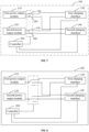
- FIG. 4 is a schematic diagram of states of switches according to an example of the present application.
- the second charging interface 140 is not connected to the second battery pack, and the first power output module 110 and the second power output module 120 supply power to the first battery pack.
- the first switch and the second switch are implemented as a first single pole, triple throw switch and the third switch and the fourth switch are implemented as a second single pole, triple throw switch
- the first single pole, triple throw switch and the second single pole, triple throw switch are set to be in the states shown in FIG. 4 so that the first power output module 110 and the second power output module 120 charge the first battery pack at the same time.
- the controller 200 turns on the second switch 160 and the fourth switch 180 and turns off the first switch 150 and the third switch 170.
- the first detection device 131 is used for determining that the load state of the first charging interface 130 is that the first charging interface 130 is connected to the first battery pack and the first battery pack is not fully charged.
- the second detection device 141 is used for determining that the load state of the second charging interface 140 is that the second charging interface 140 is connected to the second battery pack and the second battery pack is fully charged.
- the controller 200 is used for turning on the first switch 150 and the third switch 170 and turning off the second switch 160 and the fourth switch 180.
- the charging device 100 supplies power to the first battery pack through the first power output module 110 and the second power output module 120 at the same time, shortening the time for charging the first battery pack and improving the charging efficiency.
- the second switch 160 and the fourth switch 180 are turned off so that the first power output module 110 and/or the second power output module 120 do not supply power to the second charging interface, thereby avoiding energy waste.
- the corresponding power output module When no battery pack exists or when a battery pack exists but the battery pack is fully charged, the corresponding power output module is disconnected from the charging interface, and the idle power output module is connected in parallel to charge the battery pack that needs to be charged.
- the first detection device 131 is used for determining that the load state of the first charging interface 130 is that the first charging interface 130 is not connected to the first battery pack.
- the second detection device 141 is used for determining that the load state of the second charging interface 140 is that the second charging interface 140 is not connected to the second battery pack.
- the controller 200 is used for turning off the first switch, the second switch, the third switch and the fourth switch.
- the charging device 100 turns off the first switch 150, the second switch, the third switch 170 and the fourth switch 180 so that the first power output module 110 and the second power output module 120 do not supply power to the outside, thereby avoiding energy waste.
- the first switch and the second switch are implemented as a first single pole, triple throw switch and the third switch and the fourth switch are implemented as a second single pole, triple throw switch
- the first single pole, triple throw switch and the second single pole, triple throw switch are set to be in the null connection states shown in FIG. 6 so that the first power output module 110 and the second power output module 120 do not supply power to the charging interfaces.
- the first detection device 131 is used for determining that the load state of the first charging interface 130 is that the first charging interface 130 is connected to the first battery pack and the first battery pack is fully charged.
- the second detection device 141 is used for determining that the load state of the second charging interface 140 is that the second charging interface 140 is connected to the second battery pack and the second battery pack is fully charged.
- the controller 200 is used for turning off the first switch 150, the second switch 160, the third switch 170 and the fourth switch 180.
- the charging device 100 turns off the first switch 150, the second switch 160, the third switch 170 and the fourth switch 180 so that the first power output module 110 and the second power output module 120 do not supply power to the outside, thereby avoiding energy waste.
- the first detection device 131 is used for determining that the load state of the first charging interface 130 is that the first charging interface 130 is connected to the first battery pack and the first battery pack is not fully charged.
- the second detection device 141 is used for determining that the load state of the second charging interface 140 is that the second charging interface 140 is connected to the second battery pack and the second battery pack is not fully charged.
- the controller 200 is used for turning on the first switch 150 and the fourth 180 switch and turning off the second switch 160 and the third switch 170.
- the first power output module 110 supplies power to the first battery pack and the second power output module 120 supplies power to the second battery pack, thereby improving the charging efficiency.
- each of the first power output module 110 and the second power output module 120 independently charges a respective battery pack.
- FIG. 7 is a schematic diagram of states of switches according to another example of the present application.
- each of the first power output module 110 and the second power output module 120 independently supplies power to a respective charging interface.
- the first switch and the second switch are implemented as a first single pole, triple throw switch and the third switch and the fourth switch are implemented as a second single pole, triple throw switch
- the first single pole, triple throw switch and the second single pole, triple throw switch are set to be in the states shown in FIG. 8 so that each of the first power output module 110 and the second power output module 120 independently supplies power to its respective charge interface.
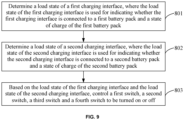
- FIG. 9 is a flowchart of a control method for a charging device according to an example of the present application.
- the control method is not covered by the scope of the appended claims but is included in this description for illustrative purposes.
- the charging device includes a first power output module, a second power output module, a first charging interface, a second charging interface, and a controller.
- a first switch is coupled between the first power output module and the first charging interface
- a second switch is coupled between the first power output module and the second charging interface
- a third switch is coupled between the second power output module and the first charging interface
- a fourth switch is coupled between the second power output module and the second charging interface.
- the method may include the steps described below.
- a load state of the first charging interface is determined, where the load state of the first charging interface is used for indicating whether the first charging interface is connected to a first battery pack and a state of charge of the first battery pack.
- a load state of the second charging interface is determined, where the load state of the second charging interface is used for indicating whether the second charging interface is connected to a second battery pack and a state of charge of the second battery pack.
- step 803 based on the load state of the first charging interface and the load state of the second charging interface, the first switch, the second switch, the third switch and the fourth switch are controlled to be turned on or off.
- Step 801 and step 802 may be performed simultaneously; or step 801 may be performed before step 802 is performed; or step 802 may be performed before step 801 is performed, which is not limited in the examples of the present application.
- step 801 includes determining that the load state of the first charging interface is that the first charging interface is connected to the first battery pack and the first battery pack is not fully charged.
- Step 802 includes determining that the load state of the second charging interface is that the second charging interface is not connected to the second battery pack.
- Step 803 includes turning on the first switch and the third switch and turning off the second switch and the fourth switch.
- step 801 includes determining that the load state of the first charging interface is that the first charging interface is connected to the first battery pack and the first battery pack is not fully charged.
- Step 802 includes determining that the load state of the second charging interface is that the second charging interface is connected to the second battery pack and the second battery pack is fully charged.
- Step 803 includes turning on the first switch and the third switch and turning off the second switch and the fourth switch.
- step 801 includes determining that the load state of the first charging interface is that the first charging interface is not connected to the first battery pack.
- Step 802 includes determining that the load state of the second charging interface is that the second charging interface is not connected to the second battery pack.
- Step 803 includes turning off the first switch, the second switch, the third switch and the fourth switch.
- step 801 includes determining that the load state of the first charging interface is that the first charging interface is connected to the first battery pack and the first battery pack is fully charged.
- Step 802 includes determining that the load state of the second charging interface is that the second charging interface is connected to the second battery pack and the second battery pack is fully charged.
- Step 803 includes turning off the first switch, the second switch, the third switch and the fourth switch.
- step 801 includes determining that the load state of the first charging interface is that the first charging interface is connected to the first battery pack and the first battery pack is not fully charged.
- Step 802 includes determining that the load state of the second charging interface is that the second charging interface is connected to the second battery pack and the second battery pack is not fully charged.
- Step 803 includes turning on the first switch and the fourth switch and turning off the second switch and the third switch.
- two charging interfaces are provided in the charging device so that two battery packs can be charged at the same time, thereby improving charging efficiency.
- the first switch is coupled between the first power output module and the first charging interface
- the second switch is coupled between the first power output module and the second charging interface
- the third switch is coupled between the second power output module and the first charging interface
- the fourth switch is coupled between the second power output module and the second charging interface
- the switches are controlled by the controller based on the load states of the charging interfaces so that the charging device can control the switches to be turned on or off according to an actual application situation, thereby improving the charging efficiency and achieving high flexibility.
- the charging device includes two charging interfaces.
- the charging device may include three or more charging interfaces, which is not limited in the examples of the present application.
Landscapes
- Engineering & Computer Science (AREA)
- Power Engineering (AREA)
- Manufacturing & Machinery (AREA)
- Chemical & Material Sciences (AREA)
- Chemical Kinetics & Catalysis (AREA)
- Electrochemistry (AREA)
- General Chemical & Material Sciences (AREA)
- Charge And Discharge Circuits For Batteries Or The Like (AREA)
- Crystals, And After-Treatments Of Crystals (AREA)
- Elimination Of Static Electricity (AREA)
Claims (15)
- Ladegerät (100), umfassend:eine erste Ladeschnittstelle (130), die mit einem ersten Batteriepack zuma Laden des ersten Batteriepacks verbindbar ist;eine zweite Ladeschnittstelle (140), die mit einem zweiten Batteriepack zum Laden des zweiten Batteriepacks verbindbar ist;ein erstes Leistungsausgabemodul (110), das mit der ersten Ladeschnittstelle verbunden ist, um das erste Batteriepack zu laden;ein zweites Leistungsausgabemodul (120), das mit der zweiten Ladeschnittstelle verbunden ist, um das zweite Batteriepack zu laden; undeine Steuereinheit (200), die mit wenigstens der ersten Ladeschnittstelle und der zweiten Ladeschnittstelle verbunden ist; wobei die Steuereinheit dafür ausgelegt ist:wenn das erste Batteriepack vollständig geladen oder nicht mit der ersten Ladeschnittstelle verbunden ist, das erste Leistungsausgabemodul und das zweite Leistungsausgabemodul so zu steuern, dass sie mit der zweiten Ladeschnittstelle verbunden werden, um das zweite Batteriepack zu laden;dadurch gekennzeichnet, dassdas erste Batteriepack ein Batteriepack eines Elektrowerkzeugs istund dass das zweite Batteriepack ein Batteriepack eines Elektrowerkzeugs ist.
- Ladegerät nach Anspruch 1, wobei ein erster Schalter (150) zwischen das erste Leistungsausgabemodul und die erste Ladeschnittstelle geschaltet ist, ein zweiter Schalter (160) zwischen das erste Leistungsausgabemodul und die zweite Ladeschnittstelle geschaltet ist, ein dritter Schalter (170) zwischen das zweite Leistungsausgabemodul und die erste Ladeschnittstelle geschaltet ist, ein vierter Schalter (180) zwischen das zweite Leistungsausgabemodul und die zweite Ladeschnittstelle geschaltet ist und die Steuereinheit dafür ausgelegt ist, das Ein- oder Ausschalten des ersten Schalters, des zweiten Schalters, des dritten Schalters und des vierten Schalters zu steuern.
- Ladegerät nach Anspruch 1, welches ferner eine erste Detektionsvorrichtung (131) zum Bestimmen eines Lastzustands der ersten Ladeschnittstelle und eine zweite Detektionsvorrichtung (141) zum Bestimmen eines Lastzustands der zweiten Ladeschnittstelle umfasst.
- Ladegerät nach Anspruch 3, wobei der Lastzustand der ersten Ladeschnittstelle verwendet wird, um anzuzeigen, ob die erste Ladeschnittstelle mit dem ersten Batteriepack verbunden ist, und einen Ladezustand des ersten Batteriepacks anzuzeigen, und der Lastzustand der zweiten Ladeschnittstelle verwendet wird, um anzuzeigen, ob die zweite Ladeschnittstelle mit dem zweiten Batteriepack verbunden ist, und einen Ladezustand des zweiten Batteriepacks anzuzeigen.
- Ladegerät nach Anspruch 4, wobei ein erster Schalter (150) zwischen das erste Leistungsausgabemodul und die erste Ladeschnittstelle geschaltet ist, ein zweiter Schalter (160) zwischen das erste Leistungsausgabemodul und die zweite Ladeschnittstelle geschaltet ist, ein dritter Schalter (170) zwischen das zweite Leistungsausgabemodul und die erste Ladeschnittstelle geschaltet ist, ein vierter Schalter (180) zwischen das zweite Leistungsausgabemodul und die zweite Ladeschnittstelle geschaltet ist und die Steuereinheit dafür ausgelegt ist, das Ein- oder Ausschalten des ersten Schalters, des zweiten Schalters, des dritten Schalters und des vierten Schalters basierend auf dem Lastzustand der ersten Ladeschnittstelle und dem Lastzustand der zweiten Ladeschnittstelle zu steuern.
- Ladegerät nach Anspruch 5, wobei die Steuereinheit dafür ausgelegt ist, den ersten Schalter und den dritten Schalter auszuschalten, wenn der von der ersten Detektionsvorrichtung bestimmte Lastzustand der ersten Ladeschnittstelle darin besteht, dass die erste Ladeschnittstelle nicht mit dem ersten Batteriepack verbunden ist oder das erste Batteriepack vollständig geladen ist.
- Ladegerät nach Anspruch 5, wobei die Steuereinheit dafür ausgelegt ist, den zweiten Schalter und den vierten Schalter auszuschalten, wenn der von der zweiten Detektionsvorrichtung bestimmte Lastzustand der zweiten Ladeschnittstelle darin besteht, dass die zweite Ladeschnittstelle nicht mit dem zweiten Batteriepack verbunden ist oder das zweite Batteriepack vollständig geladen ist.
- Ladegerät nach Anspruch 5, wobei, wenn der Lastzustand der ersten Ladeschnittstelle darin besteht, dass die erste Ladeschnittstelle mit dem ersten Batteriepack verbunden ist und das erste Batteriepack nicht vollständig geladen ist, und der Lastzustand der zweiten Ladeschnittstelle darin besteht, dass die zweite Ladeschnittstelle nicht mit dem zweiten Batteriepack verbunden ist, die Steuereinheit dafür ausgelegt ist, den ersten Schalter und den dritten Schalter so zu steuern, dass sie eingeschaltet sind, und den zweiten Schalter und den vierten Schalter so zu steuern, dass sie ausgeschaltet sind.
- Ladegerät nach Anspruch 5, wobei, wenn der Lastzustand der ersten Ladeschnittstelle darin besteht, dass die erste Ladeschnittstelle mit dem ersten Batteriepack verbunden ist und das erste Batteriepack nicht vollständig geladen ist, und der Lastzustand der zweiten Ladeschnittstelle darin besteht, dass die zweite Ladeschnittstelle mit dem zweiten Batteriepack verbunden ist und das zweite Batteriepack vollständig geladen ist, die Steuereinheit dafür ausgelegt ist, den ersten Schalter und den dritten Schalter so zu steuern, dass sie eingeschaltet sind, und den zweiten Schalter und den vierten Schalter so zu steuern, dass sie ausgeschaltet sind.
- Ladegerät nach Anspruch 5, wobei, wenn der Lastzustand der ersten Ladeschnittstelle darin besteht, dass die erste Ladeschnittstelle nicht mit dem ersten Batteriepack verbunden ist, und der Lastzustand der zweiten Ladeschnittstelle darin besteht, dass die zweite Ladeschnittstelle nicht mit dem zweiten Batteriepack verbunden ist, die Steuereinheit dafür ausgelegt ist, den ersten Schalter, den zweiten Schalter, den dritten Schalter und den vierten Schalter so zu steuern, dass sie ausgeschaltet sind.
- Ladegerät nach Anspruch 5, wobei, wenn der Lastzustand der ersten Ladeschnittstelle darin besteht, dass die erste Ladeschnittstelle mit dem ersten Batteriepack verbunden ist und das erste Batteriepack vollständig geladen ist, und der Lastzustand der zweiten Ladeschnittstelle darin besteht, dass die zweite Ladeschnittstelle mit dem zweiten Batteriepack verbunden ist und das zweite Batteriepack vollständig geladen ist, die Steuereinheit dafür ausgelegt ist, den ersten Schalter, den zweiten Schalter, den dritten Schalter und den vierten Schalter so zu steuern, dass sie ausgeschaltet sind.
- Ladegerät nach Anspruch 5, wobei, wenn der Lastzustand der ersten Ladeschnittstelle darin besteht, dass die erste Ladeschnittstelle mit dem ersten Batteriepack verbunden ist und das erste Batteriepack nicht vollständig geladen ist, und der Lastzustand der zweiten Ladeschnittstelle darin besteht, dass die zweite Ladeschnittstelle mit dem zweiten Batteriepack verbunden ist und das zweite Batteriepack nicht vollständig geladen ist, die Steuereinheit dafür ausgelegt ist, den ersten Schalter und den vierten Schalter so zu steuern, dass sie eingeschaltet sind, und den zweiten Schalter und den dritten Schalter so zu steuern, dass sie ausgeschaltet sind.
- Ladegerät nach Anspruch 5, wobei, wenn der Lastzustand der ersten Ladeschnittstelle darin besteht, dass die erste Ladeschnittstelle mit dem ersten Batteriepack verbunden ist und das erste Batteriepack nicht vollständig geladen ist, und der Lastzustand der zweiten Ladeschnittstelle darin besteht, dass die zweite Ladeschnittstelle mit dem zweiten Batteriepack verbunden ist und das zweite Batteriepack nicht vollständig geladen ist, die Steuereinheit dafür ausgelegt ist, den zweiten Schalter und den dritten Schalter so zu steuern, dass sie eingeschaltet sind, und den ersten Schalter und den vierten Schalter so zu steuern, dass sie ausgeschaltet sind.
- Ladegerät nach Anspruch 3, wobei der Lastzustand wenigstens den Ladezustand des ersten Batteriepacks oder des zweiten Batteriepacks umfasst.
- Ladegerät nach Anspruch 14, welches ferner eine erste Kommunikationsschnittstelle (132) und eine zweite Kommunikationsschnittstelle (142) umfasst; wobei die erste Kommunikationsschnittstelle mit dem ersten Batteriepack verbunden ist, um wenigstens den Ladezustand des ersten Batteriepacks zu erfassen, und die zweite Kommunikationsschnittstelle mit dem zweiten Batteriepack verbunden ist, um wenigstens den Ladezustand des zweiten Batteriepacks zu erfassen.
Applications Claiming Priority (1)
| Application Number | Priority Date | Filing Date | Title |
|---|---|---|---|
| CN202111268864 | 2021-10-29 |
Publications (2)
| Publication Number | Publication Date |
|---|---|
| EP4178068A1 EP4178068A1 (de) | 2023-05-10 |
| EP4178068B1 true EP4178068B1 (de) | 2024-04-17 |
Family
ID=83232841
Family Applications (1)
| Application Number | Title | Priority Date | Filing Date |
|---|---|---|---|
| EP22194252.7A Active EP4178068B1 (de) | 2021-10-29 | 2022-09-07 | Ladevorrichtung |
Country Status (4)
| Country | Link |
|---|---|
| US (1) | US20230138183A1 (de) |
| EP (1) | EP4178068B1 (de) |
| CN (1) | CN116073465A (de) |
| AU (1) | AU2022228178A1 (de) |
Families Citing this family (1)
| Publication number | Priority date | Publication date | Assignee | Title |
|---|---|---|---|---|
| US12051933B2 (en) * | 2022-01-02 | 2024-07-30 | Dennis M Hogan | Dual battery charging system and a method of use thereof |
Family Cites Families (148)
| Publication number | Priority date | Publication date | Assignee | Title |
|---|---|---|---|---|
| US5955867A (en) * | 1997-07-29 | 1999-09-21 | Dell Usa L.P. | Dual battery pack charging in a computer system |
| US6100670A (en) * | 1998-04-14 | 2000-08-08 | Conexant Systems, Inc. | Multi-functional battery management module operable in a charging mode and a battery pack mode |
| US6075343A (en) * | 1999-02-12 | 2000-06-13 | Quanta Computer Inc. | Rechargeable battery pack module |
| US6771056B1 (en) * | 2001-10-31 | 2004-08-03 | Ixys Corporation | AC controller with reverse blocking IGBT |
| GB2401258B (en) * | 2003-04-29 | 2005-06-22 | Research In Motion Ltd | Multiple function current-sharing charging system and method |
| US20060145659A1 (en) * | 2004-12-31 | 2006-07-06 | Joseph Patino | Battery pack system and method for waking up a charge control circuit of a mobile communication device |
| US7508162B2 (en) * | 2006-04-07 | 2009-03-24 | Nokia Corporation | Method and apparatus for providing electrical energy to a portable device from energy storage of another portable device |
| TWI325649B (en) * | 2006-07-17 | 2010-06-01 | Compal Electronics Inc | A hybrid battery module and its manufacturing, charging and discharging method |
| US9431828B2 (en) * | 2006-11-27 | 2016-08-30 | Xslent Energy Technologies | Multi-source, multi-load systems with a power extractor |
| CN201017967Y (zh) * | 2007-03-05 | 2008-02-06 | 南京德朔实业有限公司 | 一种带有自充功能的锂电系统 |
| US8035250B2 (en) * | 2008-03-14 | 2011-10-11 | Liebert Corporation | System and method for load sharing in multi-module power supply systems |
| US7880434B2 (en) * | 2008-05-21 | 2011-02-01 | Southwest Electronic Energy Corporation | System for balancing a plurality of battery pack system modules connected in series |
| DE112009001370T5 (de) * | 2008-05-27 | 2011-04-28 | ASIC Advantage, Inc., Sunnyvale | Leistungsversorgung mit Standby-Leistung |
| JP4855444B2 (ja) * | 2008-06-25 | 2012-01-18 | レノボ・シンガポール・プライベート・リミテッド | 充電制御システムおよび制御方法 |
| US8441230B2 (en) * | 2008-09-08 | 2013-05-14 | Techtronic Power Tools Technology Limited | Battery charger |
| CN104539021A (zh) * | 2008-09-08 | 2015-04-22 | 创科电动工具科技有限公司 | 电池充电器 |
| TWI379486B (en) * | 2009-02-17 | 2012-12-11 | Green Solution Tech Co Ltd | The battery charging controlling apparatus and battery balance charging controller |
| US8183870B1 (en) * | 2009-02-12 | 2012-05-22 | The United States Of America As Represented By The Administrator Of The National Aeronautics And Space Administration | Battery system and method for sensing and balancing the charge state of battery cells |
| DE102009052769B4 (de) * | 2009-11-11 | 2022-12-15 | Bayerische Motoren Werke Aktiengesellschaft | Mehrspannungsbordnetz für ein Kraftfahrzeug |
| US20110187309A1 (en) * | 2010-02-01 | 2011-08-04 | Acoustic Arc International Ltd. | Apparatus for automatically switching and charging multiple batteries |
| EP2642583A1 (de) * | 2010-03-23 | 2013-09-25 | NEC Corporation | Lade- und Entladeverfahren für Lithium-Ion-Sekundärbatterie und Lade- und Entladesystem dafür |
| KR101009485B1 (ko) * | 2010-04-20 | 2011-01-19 | (주)모던텍 | 유니버셜 충전 장치 |
| JP5453184B2 (ja) * | 2010-06-28 | 2014-03-26 | 日立ビークルエナジー株式会社 | 電池制御回路 |
| US9246340B2 (en) * | 2011-02-11 | 2016-01-26 | Intel Corporation | Battery pack |
| US9077053B2 (en) * | 2011-07-20 | 2015-07-07 | Milwaukee Electric Tool Corporation | Battery charger including multiple charging ports on surfaces forming an apex |
| WO2013097818A1 (zh) * | 2011-12-31 | 2013-07-04 | 深圳市比亚迪汽车研发有限公司 | 电动汽车的充电方法及充电装置 |
| JP5929526B2 (ja) * | 2012-06-01 | 2016-06-08 | ソニー株式会社 | 電源供給装置および電源切り換え方法 |
| TW201417452A (zh) * | 2012-10-16 | 2014-05-01 | 祥業科技股份有限公司 | 可提供交流電之行動電源 |
| US20140203780A1 (en) * | 2013-01-24 | 2014-07-24 | Texas Instruments Incorporated | System and method for active charge and discharge current balancing in multiple parallel-connected battery packs |
| TWM466420U (zh) * | 2013-03-08 | 2013-11-21 | 邱立國 | 移動電源裝置及其電源供應系統 |
| EP2879270B1 (de) * | 2013-04-17 | 2016-09-21 | Huawei Technologies Co., Ltd. | Identifikationsschaltung einer stromversorgung und stromgetriebene vorrichtung |
| WO2014196933A1 (en) * | 2013-06-06 | 2014-12-11 | Nanyang Technological University | Battery charging devices, battery charging methods, battery systems, and methods for controlling batteries |
| CN104737410B (zh) * | 2013-09-27 | 2019-03-12 | 松下知识产权经营株式会社 | 配电装置和蓄电池包的诊断方法 |
| CN106253427B (zh) * | 2014-01-28 | 2018-05-29 | 广东欧珀移动通信有限公司 | 终端及其电池充电控制装置与方法 |
| CN103762691B (zh) * | 2014-01-28 | 2015-12-23 | 广东欧珀移动通信有限公司 | 电池充电装置及电池充电保护控制方法 |
| US10305298B2 (en) * | 2014-03-17 | 2019-05-28 | Glx Power Systems, Inc. | Method and apparatus for creating a dynamically reconfigurable energy storage device |
| US9768625B2 (en) * | 2014-07-04 | 2017-09-19 | Makita Corporation | Battery pack, and method for controlling the same |
| CN104158255B (zh) * | 2014-08-20 | 2017-09-26 | 矽力杰半导体技术(杭州)有限公司 | 充放电管理系统及其应用的移动电源 |
| US10389139B2 (en) * | 2014-10-06 | 2019-08-20 | Black & Decker, Inc. | Portable power supply |
| US20160134160A1 (en) * | 2014-11-07 | 2016-05-12 | Schneider Electric It Corporation | Systems and methods for battery management |
| US9627962B2 (en) * | 2015-03-09 | 2017-04-18 | Texas Instruments Incorporated | Fast blocking switch |
| EP3068010A1 (de) * | 2015-03-10 | 2016-09-14 | HILTI Aktiengesellschaft | Netzbetreibbares Akku-Ladegerät und Ladesystem |
| US9550406B2 (en) * | 2015-03-16 | 2017-01-24 | Thunder Power Hong Kong Ltd. | Thermal dissipation system of an electric vehicle |
| US9711982B2 (en) * | 2015-03-23 | 2017-07-18 | Panasonic Intellectual Property Management Co., Ltd. | Information notifying device |
| US9742131B2 (en) * | 2015-06-09 | 2017-08-22 | O2Micro, Inc. | Power transfer systems |
| WO2017027332A1 (en) * | 2015-08-07 | 2017-02-16 | Cummins, Inc. | Systems and methods of battery management and control for a vehicle |
| KR101894777B1 (ko) * | 2015-09-22 | 2018-09-04 | 광동 오포 모바일 텔레커뮤니케이션즈 코포레이션 리미티드 | 충전 제어 방법과 장치 및 전자 기기 |
| US10424963B1 (en) * | 2016-02-18 | 2019-09-24 | Eaton Intelligent Power Limited | Methods and systems for charging a backup battery pack |
| CN210092893U (zh) * | 2016-05-25 | 2020-02-18 | 米沃奇电动工具公司 | 串联连接的电池包、系统 |
| US10439415B2 (en) * | 2016-06-08 | 2019-10-08 | Nanjing Chervon Industry Co., Ltd. | Power station |
| CN107546786B (zh) * | 2016-06-27 | 2023-12-29 | 深圳市华思旭科技有限公司 | 电源装置及供电方法 |
| CN106253399B (zh) * | 2016-08-24 | 2019-01-01 | 天津市天楚科技有限公司 | 一种移动电源 |
| CN107846046A (zh) * | 2016-09-18 | 2018-03-27 | 苏州宝时得电动工具有限公司 | 充电方法、充电装置及充电系统 |
| GB2543949B (en) * | 2016-10-03 | 2018-09-05 | O2Micro Inc | Charge/discharge switch control circuits for batteries |
| CN209488195U (zh) * | 2016-10-12 | 2019-10-11 | Oppo广东移动通信有限公司 | 移动终端 |
| KR102555753B1 (ko) * | 2016-10-18 | 2023-07-17 | 널브 스마트 시스템즈 에이피에스 | 전기차 충전용 충전소 |
| CN106564399B (zh) * | 2016-11-11 | 2018-05-15 | 深圳市沃特玛电池有限公司 | 充电站 |
| CN106585399B (zh) * | 2016-11-25 | 2018-07-24 | 深圳市沃特玛电池有限公司 | 补电车及其充放电控制电路 |
| FR3060887B1 (fr) * | 2016-12-19 | 2019-08-23 | Electricite De France | Systeme adapte pour la recharge de vehicules electriques |
| CN106786887B (zh) * | 2016-12-23 | 2019-08-23 | 捷开通讯(深圳)有限公司 | 一种充电控制系统 |
| EP3346578A3 (de) * | 2017-01-10 | 2018-09-26 | Solaredge Technologies Ltd. | Eigenständiges gleichstromnetz und verfahren |
| KR102331070B1 (ko) * | 2017-02-03 | 2021-11-25 | 삼성에스디아이 주식회사 | 배터리 팩 및 배터리 팩의 충전 제어 방법 |
| US10391864B2 (en) * | 2017-02-08 | 2019-08-27 | Toyota Motor Engineering & Manufacturing North America, Inc. | System to balance high voltage battery for vehicle |
| TWI602382B (zh) * | 2017-03-31 | 2017-10-11 | 台達電子工業股份有限公司 | 不斷電智能充電裝置及其操作方法 |
| US10924261B2 (en) * | 2017-05-22 | 2021-02-16 | Arm Limited | Efficient power distribution |
| US10997322B2 (en) * | 2017-05-22 | 2021-05-04 | Arm Limited | Efficient power distribution |
| CN109148985A (zh) * | 2017-06-15 | 2019-01-04 | 苏州宝时得电动工具有限公司 | 一种电池包充电方法及装置 |
| JP6884266B2 (ja) * | 2017-07-21 | 2021-06-09 | 華為技術有限公司Huawei Technologies Co.,Ltd. | モバイル端末、周辺デバイス、及びこれらの充電方法 |
| US20190067986A1 (en) * | 2017-08-25 | 2019-02-28 | Saudi Arabian Oil Company | Distributed Energy Storage Systems |
| CN107979125A (zh) * | 2017-09-01 | 2018-05-01 | 北京汉能光伏投资有限公司 | 太阳能辅助充电系统和控制方法 |
| WO2019071154A1 (en) * | 2017-10-06 | 2019-04-11 | Proterra Inc. | CHARGE IN DEPOSIT OF A FLEET OF ELECTRIC VEHICLES |
| US10770908B2 (en) * | 2017-10-29 | 2020-09-08 | Rivian Ip Holdings, Llc | Configurable battery pack for series and parallel charging using switching |
| KR102394826B1 (ko) * | 2018-02-14 | 2022-05-04 | 주식회사 엘지에너지솔루션 | 배터리와 평활 커패시터 간의 에너지 전달을 위한 전원 회로 및 이를 포함하는 배터리 관리 시스템 |
| TWI668939B (zh) * | 2018-04-23 | 2019-08-11 | 國立交通大學 | 結合氫燃料電池的電源供應系統 |
| WO2019242020A1 (zh) * | 2018-06-22 | 2019-12-26 | Oppo广东移动通信有限公司 | 充电装置、移动终端和充电控制方法 |
| DE102018212740A1 (de) * | 2018-07-31 | 2020-02-06 | Ads-Tec Gmbh | Ladestation für Elektroautos |
| CN113258652B (zh) * | 2018-08-01 | 2025-06-03 | Oppo广东移动通信有限公司 | 电池控制系统和方法、电子设备 |
| US10923941B2 (en) * | 2018-09-18 | 2021-02-16 | Leviton Manufacturing Company, Inc. | Systems and methods for universal serial bus (USB) power delivery with multiple charging ports |
| US12119701B2 (en) * | 2018-09-18 | 2024-10-15 | Leviton Manufacturing Co., Inc. | Systems and methods for universal serial bus (USB) power delivery with multiple charging ports |
| GB2578828B (en) * | 2018-10-22 | 2021-03-10 | O2Micro Inc | Managing power in a portable device comprising multiple batteries |
| US11677260B2 (en) * | 2018-10-22 | 2023-06-13 | O2Micro Inc. | Managing power in a portable device comprising multiple batteries |
| US11349317B2 (en) * | 2018-11-07 | 2022-05-31 | Samsung Electronics Co., Ltd. | Charger integrated circuit for charging battery device and electronic device including the charger integrated circuit |
| CN209447975U (zh) * | 2018-11-13 | 2019-09-27 | 深圳市华思旭科技有限公司 | 带车辆启动功能的电动工具电源 |
| WO2020124529A1 (zh) * | 2018-12-21 | 2020-06-25 | Oppo广东移动通信有限公司 | 充电控制装置和方法、电子设备 |
| BR112020002467A2 (pt) * | 2018-12-21 | 2021-07-13 | Guangdong Oppo Mobile Telecommunications Corp., Ltd. | circuito de abastecimento de bateria, dispositivo a ser carregado, e método de controle de carregamento |
| WO2020169209A1 (en) * | 2019-02-22 | 2020-08-27 | Incell International Ab | Reverse polarity protected battery module |
| US11901729B2 (en) * | 2019-03-11 | 2024-02-13 | Shenzhen Carku Technology Co., Limited | Charging device and emergency start method |
| EP3937292B1 (de) * | 2019-03-22 | 2024-11-27 | Guangdong Oppo Mobile Telecommunications Corp., Ltd. | Verfahren zur lade- und entladesteuerung und zu ladende vorrichtung |
| WO2020206700A1 (zh) * | 2019-04-12 | 2020-10-15 | Oppo广东移动通信有限公司 | 待充电设备及充放电控制方法 |
| CN110316008B (zh) * | 2019-06-03 | 2021-12-21 | 武汉路特斯汽车有限公司 | 一种车辆的电池系统及其进行充放电的方法 |
| US12322991B2 (en) * | 2019-06-14 | 2025-06-03 | Nanjing Chervon Industry Co., Ltd. | Battery pack and an adapter with a voltage conversion circuit |
| CN110518688A (zh) * | 2019-07-11 | 2019-11-29 | 深圳市华宝新能源股份有限公司 | 一种房车电源控制方法以及房车电源控制装置 |
| US11557796B2 (en) * | 2019-07-23 | 2023-01-17 | Cummins Inc. | DC-DC-converter-based active voltage-balancing system and method for parallel battery packs |
| CN110445213B (zh) * | 2019-08-13 | 2022-05-17 | 深圳市道通智能航空技术股份有限公司 | 一种充电管理系统、方法、装置和存储介质 |
| CN113383487A (zh) * | 2019-08-21 | 2021-09-10 | 电力集成公司 | 用于多输出充电设备的电流共享 |
| CN114008885B (zh) * | 2019-08-29 | 2024-10-01 | Oppo广东移动通信有限公司 | 待充电设备和充电方法 |
| EP4040943A4 (de) * | 2019-10-11 | 2024-01-17 | Ariens Company | Stromquelle und steuersystem für einen rasenmäher |
| WO2021075916A1 (en) * | 2019-10-17 | 2021-04-22 | Samsung Electronics Co., Ltd. | Electronic device including resonant charging circuit |
| CN112994126B (zh) * | 2019-12-13 | 2025-06-03 | 北京小米移动软件有限公司 | 充电电路、电子设备、充电方法和装置 |
| CN112968481B (zh) * | 2019-12-13 | 2023-05-30 | 北京小米移动软件有限公司 | 充电电路和电子设备 |
| CN114801828A (zh) * | 2019-12-26 | 2022-07-29 | 奥动新能源汽车科技有限公司 | 用于换电站或储能站的充电系统 |
| BR112022014549A2 (pt) * | 2020-01-24 | 2022-09-20 | Cummins Power Generation Inc | Controle de sistema de potência distribuído redundante e robusto baseado em objetos |
| US11336101B2 (en) * | 2020-02-03 | 2022-05-17 | GM Global Technology Operations LLC | Adaptive fast-charging of multi-pack battery system in a mobile platform having dual charge ports |
| KR102796270B1 (ko) * | 2020-02-05 | 2025-04-24 | 주식회사 유비파이 | 배터리 충전 관리 시스템 및 충전 관리 방법 |
| WO2021162364A1 (ko) * | 2020-02-10 | 2021-08-19 | 삼성전자 주식회사 | 충전 전압을 제어하는 전력 공급 장치 및 방법 |
| US11362524B2 (en) * | 2020-02-17 | 2022-06-14 | GM Global Technology Operations LLC | Battery system and a method for use in the battery system |
| TW202137620A (zh) * | 2020-03-25 | 2021-10-01 | 飛宏科技股份有限公司 | 雙埠電池充電系統及其充電方法 |
| EP3890135A1 (de) * | 2020-03-30 | 2021-10-06 | ABB Power Grids Switzerland AG | Sst-system mit mehreren lvdc-ausgängen |
| JP7534058B2 (ja) * | 2020-05-26 | 2024-08-14 | Fdk株式会社 | バックアップ電源装置 |
| KR102882654B1 (ko) * | 2020-06-15 | 2025-11-07 | 주식회사 엘지에너지솔루션 | 무선 충전을 위한 배터리 관리 시스템 및 배터리 랙 |
| US20220021036A1 (en) * | 2020-07-20 | 2022-01-20 | Milwaukee Electric Tool Corporation | Systems, methods, and devices for increased charging speed of lithium-based battery packs |
| US11777330B2 (en) * | 2020-07-22 | 2023-10-03 | Microsoft Technology Licensing, Llc | Common charge controller for electronic devices with multiple batteries |
| CN111987791B (zh) * | 2020-08-18 | 2024-05-24 | 百度在线网络技术(北京)有限公司 | 电池模组控制装置和方法、电源设备和系统 |
| EP4152556A4 (de) * | 2020-09-10 | 2024-05-29 | Samsung Electronics Co., Ltd. | Elektronische vorrichtung zum laden mehrerer batterien |
| EP4210193A4 (de) * | 2020-12-04 | 2024-05-08 | Samsung Electronics Co., Ltd. | Verfahren zum laden einer vielzahl von batterien und elektronische vorrichtung mit darauf angewandtem verfahren |
| WO2022121659A1 (zh) * | 2020-12-11 | 2022-06-16 | 南京泉峰科技有限公司 | 充电装置及充电系统 |
| EP4264774A4 (de) * | 2020-12-18 | 2025-04-09 | Milwaukee Electric Tool Corporation | Tragbare stromversorgung |
| CN114649843B (zh) * | 2020-12-21 | 2025-08-26 | 艾科微电子(深圳)有限公司 | 通用串行总线的充电系统与方法 |
| CN112737028B (zh) * | 2020-12-29 | 2022-12-27 | 维沃移动通信有限公司 | 充电转换设备及充电控制方法 |
| CN114696381A (zh) * | 2020-12-29 | 2022-07-01 | 李尔公司 | 用于并行电池组充电的系统和方法 |
| CN112821482B (zh) * | 2020-12-31 | 2023-06-30 | 维沃移动通信有限公司 | 充电器 |
| CN112821483B (zh) * | 2020-12-31 | 2024-01-05 | 维沃移动通信有限公司 | 充电器 |
| KR102867956B1 (ko) * | 2021-01-20 | 2025-10-10 | 삼성전자주식회사 | 외부 장치로 전원을 제공할 수 있는 전자 장치 |
| CN112910037B (zh) * | 2021-01-21 | 2024-06-04 | 华为数字能源技术有限公司 | 一种电机控制器、电机控制系统、动力总成及电动车辆 |
| CN114844135B (zh) * | 2021-02-02 | 2025-12-12 | 北京小米移动软件有限公司 | 一种充电方法、装置、终端及存储介质 |
| CN114914972A (zh) * | 2021-02-10 | 2022-08-16 | 苏州宝时得电动工具有限公司 | 电池包及电池包的充放电控制方法 |
| TWI806022B (zh) * | 2021-03-22 | 2023-06-21 | 全漢企業股份有限公司 | 多電壓輸出的電源供應裝置 |
| JP7613247B2 (ja) * | 2021-04-29 | 2025-01-15 | 株式会社オートネットワーク技術研究所 | 車載用切替装置 |
| EP4350866A4 (de) * | 2021-05-28 | 2024-12-18 | Globe (Jiangsu) Co., Ltd. | Batteriepack, elektrowerkzeugsystem und ladesystem |
| CN117441277A (zh) * | 2021-06-02 | 2024-01-23 | 唐裔隆 | 储能电源系统 |
| CN115498710A (zh) * | 2021-06-17 | 2022-12-20 | 中兴通讯股份有限公司 | 充电电路、充电方法、电子设备及存储介质 |
| US12444972B2 (en) * | 2021-06-18 | 2025-10-14 | Samsung Electronics Co., Ltd. | Power charging system and power charging method using adapter with built-in battery |
| CN215580399U (zh) * | 2021-06-18 | 2022-01-18 | 国创移动能源创新中心(江苏)有限公司 | 一种利用储能倍增的充电系统 |
| CN114008889B (zh) * | 2021-06-18 | 2024-09-20 | 武汉领普科技有限公司 | 供电电路、传感设备及其应用 |
| CN113471997A (zh) * | 2021-06-29 | 2021-10-01 | 浙江动一新能源动力科技股份有限公司 | 储能设备 |
| US20230008944A1 (en) * | 2021-07-06 | 2023-01-12 | Milwaukee Electric Tool Corporation | Constant power charging of a power tool battery pack |
| CN114498803B (zh) * | 2021-07-21 | 2023-03-24 | 荣耀终端有限公司 | 一种充放电电路和电子设备 |
| KR20230017598A (ko) * | 2021-07-28 | 2023-02-06 | 삼성전자주식회사 | 복수의 배터리 셀들을 충전하는 방법 및 그 방법을 수행하는 제어 장치 |
| CN114867633B (zh) * | 2021-08-24 | 2025-10-28 | 华为数字能源技术有限公司 | 充电系统和共享系统 |
| US12136836B2 (en) * | 2021-09-20 | 2024-11-05 | Renesas Electronics America Inc. | Multi-port charging device with multiple chargers |
| WO2023044622A1 (zh) * | 2021-09-22 | 2023-03-30 | 华为数字能源技术有限公司 | 一种充电系统 |
| EP4236008B1 (de) * | 2021-09-27 | 2025-07-16 | Contemporary Amperex Technology (Hong Kong) Limited | Batterievorrichtungsteuerungsverfahren, batterievorrichtung und medium |
| US20230097967A1 (en) * | 2021-09-30 | 2023-03-30 | Milwaukee Electric Tool Corporation | Charger including multiple adjustable power sources |
| KR20230047723A (ko) * | 2021-10-01 | 2023-04-10 | 삼성전자주식회사 | 배터리 팩 및 그 충전 제어 방법 |
| EP4344019A4 (de) * | 2021-10-28 | 2024-11-06 | Samsung Electronics Co., Ltd. | Elektronische vorrichtung und verfahren zur erhöhung der stromversorgungseffizienz einer drahtlosen ladeschaltung während der verbindung mit einem verdrahteten ladegerät |
| WO2023123173A1 (zh) * | 2021-12-30 | 2023-07-06 | 宁德时代新能源科技股份有限公司 | 电池控制电路、方法及用电装置 |
| US12051933B2 (en) * | 2022-01-02 | 2024-07-30 | Dennis M Hogan | Dual battery charging system and a method of use thereof |
| KR20230119438A (ko) * | 2022-02-07 | 2023-08-16 | 현대자동차주식회사 | 모터 구동 장치를 이용한 멀티 입력 충전 시스템 및 방법 |
-
2022
- 2022-09-07 EP EP22194252.7A patent/EP4178068B1/de active Active
- 2022-09-08 US US17/940,048 patent/US20230138183A1/en active Pending
- 2022-09-09 AU AU2022228178A patent/AU2022228178A1/en active Pending
- 2022-09-23 CN CN202211161944.8A patent/CN116073465A/zh active Pending
Also Published As
| Publication number | Publication date |
|---|---|
| AU2022228178A1 (en) | 2023-05-18 |
| CN116073465A (zh) | 2023-05-05 |
| US20230138183A1 (en) | 2023-05-04 |
| EP4178068A1 (de) | 2023-05-10 |
Similar Documents
| Publication | Publication Date | Title |
|---|---|---|
| EP3288147B1 (de) | Elektrisches werkzeug und steuerungsverfahren dafür | |
| JP7039773B2 (ja) | バッテリーパックを含む電力システム | |
| KR102247394B1 (ko) | 배터리 팩 및 이를 이용하는 배터리 구동 장치 및 배터리 구동 방법 | |
| CN102856612B (zh) | 混合动力电源系统 | |
| US11283268B2 (en) | Charger, charging system, and method for controlling charge current | |
| EP3787145A1 (de) | Stromversorgungssystem mit mehreren batterien | |
| CN102113192A (zh) | 多功能便携式储存及供应系统 | |
| US11451078B2 (en) | Electric tool power supply having vehicle starting function | |
| KR102200551B1 (ko) | 배터리 팩 | |
| JP4488381B2 (ja) | 電池パックシステム | |
| US20170331305A1 (en) | Adapter, power supply device, and over-discharge protection method | |
| JP2024133685A (ja) | 充電システム、バッテリパック | |
| CN103227487B (zh) | 电动自行车用燃料电池/锂离子电池混合动力能量管理系统 | |
| EP4178068B1 (de) | Ladevorrichtung | |
| CA3180316A1 (en) | Charging device and control method therefor | |
| CN216720949U (zh) | 充放电保护装置和启动电源设备 | |
| CN212343374U (zh) | 一种可变压锂电池组的保护电路 | |
| CN112087011A (zh) | 一种电池包 | |
| CN210608615U (zh) | 锂离子电池充放电硬件二次防护电路 | |
| CN112087007A (zh) | 一种电池包 | |
| EP3971472B1 (de) | Nutzlicht, kombination aus batteriepack und nutzlicht und elektrowerkzeug | |
| CN116054293A (zh) | 适用于电动工具的电池包及电动工具 | |
| CN105743188A (zh) | 铅酸电池组保护系统 | |
| CN218805248U (zh) | 一种适用于agv用无缝快换锂离子电源系统 | |
| CN223472045U (zh) | 充电电路和储能设备 |
Legal Events
| Date | Code | Title | Description |
|---|---|---|---|
| PUAI | Public reference made under article 153(3) epc to a published international application that has entered the european phase |
Free format text: ORIGINAL CODE: 0009012 |
|
| STAA | Information on the status of an ep patent application or granted ep patent |
Free format text: STATUS: THE APPLICATION HAS BEEN PUBLISHED |
|
| AK | Designated contracting states |
Kind code of ref document: A1 Designated state(s): AL AT BE BG CH CY CZ DE DK EE ES FI FR GB GR HR HU IE IS IT LI LT LU LV MC MK MT NL NO PL PT RO RS SE SI SK SM TR |
|
| STAA | Information on the status of an ep patent application or granted ep patent |
Free format text: STATUS: REQUEST FOR EXAMINATION WAS MADE |
|
| 17P | Request for examination filed |
Effective date: 20231011 |
|
| RBV | Designated contracting states (corrected) |
Designated state(s): AL AT BE BG CH CY CZ DE DK EE ES FI FR GB GR HR HU IE IS IT LI LT LU LV MC MK MT NL NO PL PT RO RS SE SI SK SM TR |
|
| GRAP | Despatch of communication of intention to grant a patent |
Free format text: ORIGINAL CODE: EPIDOSNIGR1 |
|
| STAA | Information on the status of an ep patent application or granted ep patent |
Free format text: STATUS: GRANT OF PATENT IS INTENDED |
|
| GRAS | Grant fee paid |
Free format text: ORIGINAL CODE: EPIDOSNIGR3 |
|
| INTG | Intention to grant announced |
Effective date: 20240216 |
|
| GRAA | (expected) grant |
Free format text: ORIGINAL CODE: 0009210 |
|
| STAA | Information on the status of an ep patent application or granted ep patent |
Free format text: STATUS: THE PATENT HAS BEEN GRANTED |
|
| AK | Designated contracting states |
Kind code of ref document: B1 Designated state(s): AL AT BE BG CH CY CZ DE DK EE ES FI FR GB GR HR HU IE IS IT LI LT LU LV MC MK MT NL NO PL PT RO RS SE SI SK SM TR |
|
| REG | Reference to a national code |
Ref country code: GB Ref legal event code: FG4D |
|
| REG | Reference to a national code |
Ref country code: CH Ref legal event code: EP |
|
| REG | Reference to a national code |
Ref country code: DE Ref legal event code: R096 Ref document number: 602022002913 Country of ref document: DE |
|
| REG | Reference to a national code |
Ref country code: IE Ref legal event code: FG4D |
|
| REG | Reference to a national code |
Ref country code: LT Ref legal event code: MG9D |
|
| REG | Reference to a national code |
Ref country code: NL Ref legal event code: MP Effective date: 20240417 |
|
| REG | Reference to a national code |
Ref country code: AT Ref legal event code: MK05 Ref document number: 1678204 Country of ref document: AT Kind code of ref document: T Effective date: 20240417 |
|
| PG25 | Lapsed in a contracting state [announced via postgrant information from national office to epo] |
Ref country code: NL Free format text: LAPSE BECAUSE OF FAILURE TO SUBMIT A TRANSLATION OF THE DESCRIPTION OR TO PAY THE FEE WITHIN THE PRESCRIBED TIME-LIMIT Effective date: 20240417 |
|
| PG25 | Lapsed in a contracting state [announced via postgrant information from national office to epo] |
Ref country code: NL Free format text: LAPSE BECAUSE OF FAILURE TO SUBMIT A TRANSLATION OF THE DESCRIPTION OR TO PAY THE FEE WITHIN THE PRESCRIBED TIME-LIMIT Effective date: 20240417 |
|
| PG25 | Lapsed in a contracting state [announced via postgrant information from national office to epo] |
Ref country code: IS Free format text: LAPSE BECAUSE OF FAILURE TO SUBMIT A TRANSLATION OF THE DESCRIPTION OR TO PAY THE FEE WITHIN THE PRESCRIBED TIME-LIMIT Effective date: 20240817 |
|
| PG25 | Lapsed in a contracting state [announced via postgrant information from national office to epo] |
Ref country code: BG Free format text: LAPSE BECAUSE OF FAILURE TO SUBMIT A TRANSLATION OF THE DESCRIPTION OR TO PAY THE FEE WITHIN THE PRESCRIBED TIME-LIMIT Effective date: 20240417 |
|
| PG25 | Lapsed in a contracting state [announced via postgrant information from national office to epo] |
Ref country code: HR Free format text: LAPSE BECAUSE OF FAILURE TO SUBMIT A TRANSLATION OF THE DESCRIPTION OR TO PAY THE FEE WITHIN THE PRESCRIBED TIME-LIMIT Effective date: 20240417 Ref country code: FI Free format text: LAPSE BECAUSE OF FAILURE TO SUBMIT A TRANSLATION OF THE DESCRIPTION OR TO PAY THE FEE WITHIN THE PRESCRIBED TIME-LIMIT Effective date: 20240417 |
|
| PG25 | Lapsed in a contracting state [announced via postgrant information from national office to epo] |
Ref country code: GR Free format text: LAPSE BECAUSE OF FAILURE TO SUBMIT A TRANSLATION OF THE DESCRIPTION OR TO PAY THE FEE WITHIN THE PRESCRIBED TIME-LIMIT Effective date: 20240718 |
|
| PG25 | Lapsed in a contracting state [announced via postgrant information from national office to epo] |
Ref country code: PT Free format text: LAPSE BECAUSE OF FAILURE TO SUBMIT A TRANSLATION OF THE DESCRIPTION OR TO PAY THE FEE WITHIN THE PRESCRIBED TIME-LIMIT Effective date: 20240819 |
|
| PG25 | Lapsed in a contracting state [announced via postgrant information from national office to epo] |
Ref country code: ES Free format text: LAPSE BECAUSE OF FAILURE TO SUBMIT A TRANSLATION OF THE DESCRIPTION OR TO PAY THE FEE WITHIN THE PRESCRIBED TIME-LIMIT Effective date: 20240417 |
|
| PG25 | Lapsed in a contracting state [announced via postgrant information from national office to epo] |
Ref country code: AT Free format text: LAPSE BECAUSE OF FAILURE TO SUBMIT A TRANSLATION OF THE DESCRIPTION OR TO PAY THE FEE WITHIN THE PRESCRIBED TIME-LIMIT Effective date: 20240417 |
|
| PG25 | Lapsed in a contracting state [announced via postgrant information from national office to epo] |
Ref country code: PL Free format text: LAPSE BECAUSE OF FAILURE TO SUBMIT A TRANSLATION OF THE DESCRIPTION OR TO PAY THE FEE WITHIN THE PRESCRIBED TIME-LIMIT Effective date: 20240417 |
|
| PG25 | Lapsed in a contracting state [announced via postgrant information from national office to epo] |
Ref country code: LV Free format text: LAPSE BECAUSE OF FAILURE TO SUBMIT A TRANSLATION OF THE DESCRIPTION OR TO PAY THE FEE WITHIN THE PRESCRIBED TIME-LIMIT Effective date: 20240417 |
|
| PG25 | Lapsed in a contracting state [announced via postgrant information from national office to epo] |
Ref country code: PT Free format text: LAPSE BECAUSE OF FAILURE TO SUBMIT A TRANSLATION OF THE DESCRIPTION OR TO PAY THE FEE WITHIN THE PRESCRIBED TIME-LIMIT Effective date: 20240819 Ref country code: PL Free format text: LAPSE BECAUSE OF FAILURE TO SUBMIT A TRANSLATION OF THE DESCRIPTION OR TO PAY THE FEE WITHIN THE PRESCRIBED TIME-LIMIT Effective date: 20240417 Ref country code: NO Free format text: LAPSE BECAUSE OF FAILURE TO SUBMIT A TRANSLATION OF THE DESCRIPTION OR TO PAY THE FEE WITHIN THE PRESCRIBED TIME-LIMIT Effective date: 20240717 Ref country code: LV Free format text: LAPSE BECAUSE OF FAILURE TO SUBMIT A TRANSLATION OF THE DESCRIPTION OR TO PAY THE FEE WITHIN THE PRESCRIBED TIME-LIMIT Effective date: 20240417 Ref country code: IS Free format text: LAPSE BECAUSE OF FAILURE TO SUBMIT A TRANSLATION OF THE DESCRIPTION OR TO PAY THE FEE WITHIN THE PRESCRIBED TIME-LIMIT Effective date: 20240817 Ref country code: HR Free format text: LAPSE BECAUSE OF FAILURE TO SUBMIT A TRANSLATION OF THE DESCRIPTION OR TO PAY THE FEE WITHIN THE PRESCRIBED TIME-LIMIT Effective date: 20240417 Ref country code: GR Free format text: LAPSE BECAUSE OF FAILURE TO SUBMIT A TRANSLATION OF THE DESCRIPTION OR TO PAY THE FEE WITHIN THE PRESCRIBED TIME-LIMIT Effective date: 20240718 Ref country code: FI Free format text: LAPSE BECAUSE OF FAILURE TO SUBMIT A TRANSLATION OF THE DESCRIPTION OR TO PAY THE FEE WITHIN THE PRESCRIBED TIME-LIMIT Effective date: 20240417 Ref country code: ES Free format text: LAPSE BECAUSE OF FAILURE TO SUBMIT A TRANSLATION OF THE DESCRIPTION OR TO PAY THE FEE WITHIN THE PRESCRIBED TIME-LIMIT Effective date: 20240417 Ref country code: BG Free format text: LAPSE BECAUSE OF FAILURE TO SUBMIT A TRANSLATION OF THE DESCRIPTION OR TO PAY THE FEE WITHIN THE PRESCRIBED TIME-LIMIT Effective date: 20240417 Ref country code: AT Free format text: LAPSE BECAUSE OF FAILURE TO SUBMIT A TRANSLATION OF THE DESCRIPTION OR TO PAY THE FEE WITHIN THE PRESCRIBED TIME-LIMIT Effective date: 20240417 Ref country code: RS Free format text: LAPSE BECAUSE OF FAILURE TO SUBMIT A TRANSLATION OF THE DESCRIPTION OR TO PAY THE FEE WITHIN THE PRESCRIBED TIME-LIMIT Effective date: 20240717 |
|
| PG25 | Lapsed in a contracting state [announced via postgrant information from national office to epo] |
Ref country code: DK Free format text: LAPSE BECAUSE OF FAILURE TO SUBMIT A TRANSLATION OF THE DESCRIPTION OR TO PAY THE FEE WITHIN THE PRESCRIBED TIME-LIMIT Effective date: 20240417 |
|
| REG | Reference to a national code |
Ref country code: DE Ref legal event code: R097 Ref document number: 602022002913 Country of ref document: DE |
|
| PG25 | Lapsed in a contracting state [announced via postgrant information from national office to epo] |
Ref country code: EE Free format text: LAPSE BECAUSE OF FAILURE TO SUBMIT A TRANSLATION OF THE DESCRIPTION OR TO PAY THE FEE WITHIN THE PRESCRIBED TIME-LIMIT Effective date: 20240417 |
|
| PG25 | Lapsed in a contracting state [announced via postgrant information from national office to epo] |
Ref country code: CZ Free format text: LAPSE BECAUSE OF FAILURE TO SUBMIT A TRANSLATION OF THE DESCRIPTION OR TO PAY THE FEE WITHIN THE PRESCRIBED TIME-LIMIT Effective date: 20240417 |
|
| PG25 | Lapsed in a contracting state [announced via postgrant information from national office to epo] |
Ref country code: SK Free format text: LAPSE BECAUSE OF FAILURE TO SUBMIT A TRANSLATION OF THE DESCRIPTION OR TO PAY THE FEE WITHIN THE PRESCRIBED TIME-LIMIT Effective date: 20240417 Ref country code: RO Free format text: LAPSE BECAUSE OF FAILURE TO SUBMIT A TRANSLATION OF THE DESCRIPTION OR TO PAY THE FEE WITHIN THE PRESCRIBED TIME-LIMIT Effective date: 20240417 |
|
| PG25 | Lapsed in a contracting state [announced via postgrant information from national office to epo] |
Ref country code: SM Free format text: LAPSE BECAUSE OF FAILURE TO SUBMIT A TRANSLATION OF THE DESCRIPTION OR TO PAY THE FEE WITHIN THE PRESCRIBED TIME-LIMIT Effective date: 20240417 |
|
| PG25 | Lapsed in a contracting state [announced via postgrant information from national office to epo] |
Ref country code: SM Free format text: LAPSE BECAUSE OF FAILURE TO SUBMIT A TRANSLATION OF THE DESCRIPTION OR TO PAY THE FEE WITHIN THE PRESCRIBED TIME-LIMIT Effective date: 20240417 Ref country code: SK Free format text: LAPSE BECAUSE OF FAILURE TO SUBMIT A TRANSLATION OF THE DESCRIPTION OR TO PAY THE FEE WITHIN THE PRESCRIBED TIME-LIMIT Effective date: 20240417 Ref country code: RO Free format text: LAPSE BECAUSE OF FAILURE TO SUBMIT A TRANSLATION OF THE DESCRIPTION OR TO PAY THE FEE WITHIN THE PRESCRIBED TIME-LIMIT Effective date: 20240417 Ref country code: EE Free format text: LAPSE BECAUSE OF FAILURE TO SUBMIT A TRANSLATION OF THE DESCRIPTION OR TO PAY THE FEE WITHIN THE PRESCRIBED TIME-LIMIT Effective date: 20240417 Ref country code: DK Free format text: LAPSE BECAUSE OF FAILURE TO SUBMIT A TRANSLATION OF THE DESCRIPTION OR TO PAY THE FEE WITHIN THE PRESCRIBED TIME-LIMIT Effective date: 20240417 Ref country code: CZ Free format text: LAPSE BECAUSE OF FAILURE TO SUBMIT A TRANSLATION OF THE DESCRIPTION OR TO PAY THE FEE WITHIN THE PRESCRIBED TIME-LIMIT Effective date: 20240417 |
|
| PG25 | Lapsed in a contracting state [announced via postgrant information from national office to epo] |
Ref country code: IT Free format text: LAPSE BECAUSE OF FAILURE TO SUBMIT A TRANSLATION OF THE DESCRIPTION OR TO PAY THE FEE WITHIN THE PRESCRIBED TIME-LIMIT Effective date: 20240417 |
|
| PLBE | No opposition filed within time limit |
Free format text: ORIGINAL CODE: 0009261 |
|
| STAA | Information on the status of an ep patent application or granted ep patent |
Free format text: STATUS: NO OPPOSITION FILED WITHIN TIME LIMIT |
|
| 26N | No opposition filed |
Effective date: 20250120 |
|
| PG25 | Lapsed in a contracting state [announced via postgrant information from national office to epo] |
Ref country code: SI Free format text: LAPSE BECAUSE OF FAILURE TO SUBMIT A TRANSLATION OF THE DESCRIPTION OR TO PAY THE FEE WITHIN THE PRESCRIBED TIME-LIMIT Effective date: 20240417 Ref country code: MC Free format text: LAPSE BECAUSE OF FAILURE TO SUBMIT A TRANSLATION OF THE DESCRIPTION OR TO PAY THE FEE WITHIN THE PRESCRIBED TIME-LIMIT Effective date: 20240417 |
|
| PG25 | Lapsed in a contracting state [announced via postgrant information from national office to epo] |
Ref country code: LU Free format text: LAPSE BECAUSE OF NON-PAYMENT OF DUE FEES Effective date: 20240907 |
|
| REG | Reference to a national code |
Ref country code: BE Ref legal event code: MM Effective date: 20240930 |
|
| PG25 | Lapsed in a contracting state [announced via postgrant information from national office to epo] |
Ref country code: BE Free format text: LAPSE BECAUSE OF NON-PAYMENT OF DUE FEES Effective date: 20240930 |
|
| PG25 | Lapsed in a contracting state [announced via postgrant information from national office to epo] |
Ref country code: IE Free format text: LAPSE BECAUSE OF NON-PAYMENT OF DUE FEES Effective date: 20240907 |
|
| PG25 | Lapsed in a contracting state [announced via postgrant information from national office to epo] |
Ref country code: SE Free format text: LAPSE BECAUSE OF FAILURE TO SUBMIT A TRANSLATION OF THE DESCRIPTION OR TO PAY THE FEE WITHIN THE PRESCRIBED TIME-LIMIT Effective date: 20240417 |
|
| PGFP | Annual fee paid to national office [announced via postgrant information from national office to epo] |
Ref country code: DE Payment date: 20250730 Year of fee payment: 4 |
|
| PGFP | Annual fee paid to national office [announced via postgrant information from national office to epo] |
Ref country code: FR Payment date: 20250808 Year of fee payment: 4 |
|
| PG25 | Lapsed in a contracting state [announced via postgrant information from national office to epo] |
Ref country code: CY Free format text: LAPSE BECAUSE OF FAILURE TO SUBMIT A TRANSLATION OF THE DESCRIPTION OR TO PAY THE FEE WITHIN THE PRESCRIBED TIME-LIMIT; INVALID AB INITIO Effective date: 20220907 |
|
| PG25 | Lapsed in a contracting state [announced via postgrant information from national office to epo] |
Ref country code: HU Free format text: LAPSE BECAUSE OF FAILURE TO SUBMIT A TRANSLATION OF THE DESCRIPTION OR TO PAY THE FEE WITHIN THE PRESCRIBED TIME-LIMIT; INVALID AB INITIO Effective date: 20220907 |