EP3971472B1 - Nutzlicht, kombination aus batteriepack und nutzlicht und elektrowerkzeug - Google Patents
Nutzlicht, kombination aus batteriepack und nutzlicht und elektrowerkzeug Download PDFInfo
- Publication number
- EP3971472B1 EP3971472B1 EP20915320.4A EP20915320A EP3971472B1 EP 3971472 B1 EP3971472 B1 EP 3971472B1 EP 20915320 A EP20915320 A EP 20915320A EP 3971472 B1 EP3971472 B1 EP 3971472B1
- Authority
- EP
- European Patent Office
- Prior art keywords
- direct current
- current interface
- external power
- power
- power supply
- Prior art date
- Legal status (The legal status is an assumption and is not a legal conclusion. Google has not performed a legal analysis and makes no representation as to the accuracy of the status listed.)
- Active
Links
Images

Classifications
-
- B—PERFORMING OPERATIONS; TRANSPORTING
- B25—HAND TOOLS; PORTABLE POWER-DRIVEN TOOLS; MANIPULATORS
- B25F—COMBINATION OR MULTI-PURPOSE TOOLS NOT OTHERWISE PROVIDED FOR; DETAILS OR COMPONENTS OF PORTABLE POWER-DRIVEN TOOLS NOT PARTICULARLY RELATED TO THE OPERATIONS PERFORMED AND NOT OTHERWISE PROVIDED FOR
- B25F5/00—Details or components of portable power-driven tools not particularly related to the operations performed and not otherwise provided for
-
- F—MECHANICAL ENGINEERING; LIGHTING; HEATING; WEAPONS; BLASTING
- F21—LIGHTING
- F21L—LIGHTING DEVICES OR SYSTEMS THEREOF, BEING PORTABLE OR SPECIALLY ADAPTED FOR TRANSPORTATION
- F21L4/00—Electric lighting devices with self-contained electric batteries or cells
-
- F—MECHANICAL ENGINEERING; LIGHTING; HEATING; WEAPONS; BLASTING
- F21—LIGHTING
- F21L—LIGHTING DEVICES OR SYSTEMS THEREOF, BEING PORTABLE OR SPECIALLY ADAPTED FOR TRANSPORTATION
- F21L4/00—Electric lighting devices with self-contained electric batteries or cells
- F21L4/08—Electric lighting devices with self-contained electric batteries or cells characterised by means for in situ recharging of the batteries or cells
-
- H—ELECTRICITY
- H02—GENERATION; CONVERSION OR DISTRIBUTION OF ELECTRIC POWER
- H02J—CIRCUIT ARRANGEMENTS OR SYSTEMS FOR SUPPLYING OR DISTRIBUTING ELECTRIC POWER; SYSTEMS FOR STORING ELECTRIC ENERGY
- H02J7/00—Circuit arrangements for charging or depolarising batteries or for supplying loads from batteries
- H02J7/0068—Battery or charger load switching, e.g. concurrent charging and load supply
-
- H—ELECTRICITY
- H02—GENERATION; CONVERSION OR DISTRIBUTION OF ELECTRIC POWER
- H02J—CIRCUIT ARRANGEMENTS OR SYSTEMS FOR SUPPLYING OR DISTRIBUTING ELECTRIC POWER; SYSTEMS FOR STORING ELECTRIC ENERGY
- H02J2207/00—Indexing scheme relating to details of circuit arrangements for charging or depolarising batteries or for supplying loads from batteries
- H02J2207/20—Charging or discharging characterised by the power electronics converter
Definitions
- the present application relates to the field of power equipment, for example, a tool lamp, a combination of a battery pack and a tool lamp, and a power tool.
- the power equipment is generally powered by a battery pack or a built-in cell, and when the battery pack or the cell is exhausted, the power equipment can continue to operate only after the battery pack or the cell is fully charged.
- portable equipment generally can only accept the input of external power, and an existing power tool needs to be equipped with a special charger for charging the battery pack so that in an emergency, the equipment cannot be adapted to the power supply of an external electronic device, thereby limiting the use of the equipment.
- the power tool needs to be equipped with a special adapter connected to the external electronic device.
- an existing charger and adapter have relatively complicated structures and relatively high manufacturing costs and are bulky and inconvenient to CN208890421U and CN204497813U disclose battery driven power tools.
- an object of the present application is to provide an adapter and a combination of a battery pack and an adapter, which have relatively low costs, are convenient to carry, and can expand the use of a battery pack of a power tool.
- a power tool includes a power module, a direct current interface, and a two-way control module.
- the power module includes a motor and a cell, where the motor is configured to drive an output unit to output power to an outside, and the cell supplies electric power to the motor.
- the direct current interface is configured to be capable of being selectively connected to an external power consumption device or an external power supply device.
- the two-way control module is connected in series between the direct current interface and the power module, where the two-way control module is configured to adjust electric power of the external power supply device according to a control signal of the direct current interface to form an electric power input adapted to the cell and/or the motor so that the external power supply device supplies power to the cell and/or the motor; or the two-way control module is configured to match a discharge voltage of the cell with a charge voltage required by the external power consumption device according to the control signal of the direct current interface so that the external power consumption device is charged.
- the two-way control module includes a voltage conversion circuit, a main controller, and a two-way power supply controller.
- the voltage conversion circuit is connected to an adapter interface, where the voltage conversion circuit is configured to convert the electric power of the external power supply device into the electric power input adapted to the cell and/or the motor; or the voltage conversion circuit is configured to convert an electric power of the cell into an electric power output adapted to the external power consumption device.
- the main controller is connected to the direct current interface, where the main controller is configured to output a control signal to a two-way power supply controller according to a state signal of the direct current interface and a state signal of the adapter interface.
- the two-way power supply controller is connected to the voltage conversion circuit and the main controller, respectively, where the two-way power supply controller is configured to control a current direction and an output voltage of the voltage conversion circuit according to the control signal of the main controller so that the external power supply device supplies power to the cell and/or the motor or the cell is discharged to supply power to the external power consumption device.
- the main controller further includes a communication terminal communicatively connected to the motor, and the main controller controls the current direction of the voltage conversion circuit according to communication information of the motor so that the external power supply device supplies power to the motor.
- the direct current interface includes a detection terminal and an electric power terminal, where the detection terminal detects the state signal of the direct current interface, and the electric power terminal is configured to output or input electric power.
- the electric power terminal includes at least two power positive terminals, where the at least two power positive terminals are connected to a positive electrode of the external power consumption device or a positive electrode of the external power supply device.
- the state signal includes at least a charge signal and a discharge signal.
- the detection terminal detects the charge signal of the direct current interface and sends a charge control signal to the main controller so that the main controller controls the current direction of the voltage conversion circuit and thus the external power supply device charges the cell.
- the detection terminal detects a high level, it is determined that the direct current interface receives the charge signal.
- the detection terminal detects the discharge signal of the direct current interface and sends a discharge control signal to the main controller so that the main controller controls the current direction of the voltage conversion circuit and thus the cell is discharged to supply power to the external power consumption device.
- the detection terminal detects a low level, it is determined that the direct current interface receives the discharge signal.
- the power tool in the present application is provided with the direct current interface and the two-way control module, which expands the use of the power tool and is convenient for a user to use. It is to be understood that since a design circuit architecture of the two-way power supply controller is adopted in the power tool, the charge and discharge control can be achieved through the same controller, which reduces the introduction of other operational amplifier circuits and simplifies the circuit structure.
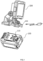
- a combination of a battery pack 100 and a tool lamp 200 in an embodiment of the present application includes the battery pack 100 and the tool lamp 200.
- the battery pack 100 is configured to supply power to the tool lamp 200 and includes a cell for storing electric power and at least one battery pack interface 110 that can be detachably connected to the tool lamp 200, where the battery pack interface 110 is provided with a battery pack terminal electrically connected to the tool lamp 200.
- the tool lamp 200 is specifically a hand-held lighting lamp.
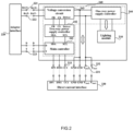
- the tool lamp 200 includes a lighting module 210, an adapter interface 220, a direct current interface 230, and a circuit board unit 240.
- the lighting module 210 is a light-emitting diode (LED) light-emitting module.
- LED light-emitting diode
- the lighting module 210 may also be configured to be other light-emitting units, as long as a lighting function is satisfied, which is not limited herein.
- the adapter interface 220 is configured to be detachably connected to the battery pack interface 110 of the battery pack 100.
- the adapter interface 220 includes an adapter positive terminal 221, an adapter negative terminal 222, and an adapter communication terminal 223, where the adapter positive terminal 221 and the adapter negative terminal 222 are electrically connected to the battery pack terminal.
- the direct current interface 230 is configured to be capable of being selectively connected to an external power consumption device or an external power supply device. In the case where the direct current interface 230 is in a charge state, electric power from the external power supply device is received; and in the case where the direct current interface 230 is in a discharge state, electric power of the battery pack 100 is supplied to the external power consumption device.
- the direct current interface 230 includes a detection terminal 233 and an electric power terminal, where the detection terminal 233 detects a state signal of the direct current interface 230, and the electric power terminal is configured to output or input electric power.
- the electric power terminal of the direct current interface 230 includes at least two power positive terminals.
- Two power positive terminals are a first electric power terminal 231 and a second electric power terminal 232, respectively, such as Vbus1 and Vbus2.
- the first electric power terminal 231 and the second electric power terminal 232 can be connected to a positive terminal of the external power consumption device or a positive terminal of the external power supply device and are configured to input or output electric power.
- the output or input power of the direct current interface is P, where P ⁇ 100 W; or 100 W ⁇ P ⁇ 200 W; or 200 W ⁇ P ⁇ 500 W.
- the output or input voltage of the direct current interface is U, where U ⁇ 20 V; or 20 V ⁇ U ⁇ 60 V; 60 V ⁇ U ⁇ 100V.
- the direct current interface 230 further includes the detection terminal 233 such as CC1.
- the detection terminal 233 is configured to detect the state signal of the direct current interface 230, where the direct current interface 230 has the charge state, the discharge state, and an empty state.
- the detection terminal 233 detects a high level, the external power supply device is equivalent to a pull-up resistor, it is determined that the direct current interface 230 is a power supply side, the battery pack 100 is equivalent to a pull-down resistor and determined as a power receiving side, and the detection terminal 233 determines that the direct current interface 230 is in the charge state and sends a charge control signal to the circuit board unit 240 so that the external power supply device charges the battery pack 100.
- the detection terminal 233 detects a low level, the external power consumption device is equivalent to a pull-down resistor, it is determined that the direct current interface 230 is a power receiving side, the battery pack 100 is equivalent to a pull-up resistor and determined as a power supply side, and the detection terminal 233 determines that the direct current interface 230 is in the discharge state and sends a discharge control signal to the circuit board unit 240 so that the battery pack 100 is discharged to supply power to the external power consumption device.
- the circuit board unit 240 is connected in series between the adapter interface 220 and the direct current interface 230; the circuit board unit 240 includes a two-way control module and a one-way control module.
- the circuit board unit 240 may be one circuit board or may be integrated by multiple circuit boards, which is not limited herein.
- the two-way control module is connected in series between the direct current interface 230 and the adapter interface 220, where the two-way control module is configured to adjust electric power of the external power supply device according to a control signal of the direct current interface 230 to form an electric power input adapted to the battery pack 100 so that the external power supply device charges the battery pack 100; or the two-way control module is configured to match a discharge voltage of the battery pack 100 with a power supply voltage required by the external power consumption device according to the control signal of the direct current interface 230 so that the external power consumption device is powered.
- the two-way control module includes a main controller 241, a two-way power supply controller 242, and a voltage conversion circuit 243 that are disposed on the circuit board unit 240.
- the detection terminal 233 detects a charge signal and determines that the direct current interface 230 is in the charge state, and the detection terminal 233 sends the charge control signal to the main controller 241; the main controller 241 outputs a control signal to the two-way power supply controller 242 according to the charge control signal; the two-way power supply controller 242 receives the control signal from the main controller 241 and outputs a power supply control signal to the voltage conversion circuit 243 to control a current direction of the voltage conversion circuit 243 and control the voltage conversion circuit 243 to adjust the electric power of the external power supply device to form the electric power input adapted to the battery pack 100 so that the external power supply device supplies power to the battery pack 100.
- the main controller 241 can also receive related communication signals from the communication terminal 223 of the battery pack 100 to send power supply information adapted to the battery pack 100 to the main controller 241, such as voltage and current information.
- the main controller 241 sends the control signal to the two-way power supply controller 242 according to the power supply information, and finally, the two-way power supply controller 242 outputs the power supply control signal to the voltage conversion circuit 243 to adjust electric power input by the external power supply device to the battery pack 100.
- the detection terminal 233 detects a direction signal and determines that the direct current interface 230 is in the discharge state, and the detection terminal 233 sends the discharge control signal to the main controller 241; the main controller 241 outputs a control signal to the two-way power supply controller 242 according to the discharge control signal; the two-way power supply controller 242 receives the control signal from the main controller 241 and outputs a power supply control signal to the voltage conversion circuit 243 to control a current direction of the voltage conversion circuit 243, and the voltage conversion circuit 243 matches the discharge voltage of the battery pack 100 with the power supply voltage required by the external power consumption device so that the external power consumption device is powered.
- an external power supply device of a smartphone or a laptop available on site may be used to supply power to the battery pack 100 through the direct current interface, and the battery pack 100 may also output the electric power stored in the cell to supply power to an external power consumption device such as the smartphone or the laptop.
- the power supply includes a case where electric power is directly supplied to the external power consumption device for its use and a case where the external power consumption device is charged.
- the tool lamp in the present application is provided with the direct current interface, the two-way control module, and the one-way control module, which expands the use of the tool lamp and is convenient for a user to use. It is to be understood that since a design circuit architecture of the two-way power supply controller is adopted in the tool lamp, the charge and discharge control can be achieved through the same controller, which reduces the introduction of other operational amplifier circuits and simplifies the circuit structure.
- the one-way control module is connected in series between the direct current interface 230 and the lighting module 210 and connected in series between the adapter interface 220 and the lighting module 210, where the one-way control module is configured to convert the electric power of the external power supply device or the electric power of the battery pack 100 into an electric power input adapted to the lighting module 210.
- the one-way control module includes a one-way power supply controller 244 disposed on the circuit board unit 240 and connected in series between the direct current interface 230 and the lighting module 210.
- the one-way power supply controller 244 receives and adjusts the electric power from the external power supply device to form the electric power input adapted to the lighting module 210 so that the external power supply device supplies power to the lighting tool 210.
- the one-way power supply controller 244 is also connected in series between the voltage conversion circuit 243 and the lighting module 210. In the case where the adapter interface 220 is connected to the battery pack 100, the one-way power supply controller 244 receives and adjusts the electric power of the battery pack 100 to form the electric power input adapted to the lighting module 210 so that the battery pack 100 supplies power to the lighting tool 210.
- the tool lamp may be connected to the external power supply device or the external power consumption device through an adapter, and the adapter can make the tool lamp output electric power and can also supply electric power to charge the tool lamp and/or the battery pack.
- the adapter may include a power plug and an output interface; of course, the adapter may also include an input interface and an output interface that are configured to be connected to the tool lamp and the external power supply device or the external power consumption device, respectively.
- the external power supply device supplies power to the lighting module 210 through the one-way control module, and the lighting module 210 can perform lighting. In this case, the adapter interface 220 is not powered on.
- the main controller 241 receives a signal from the adapter communication terminal 223 of the battery pack 100, the external power supply device supplies power to the lighting module 210 through the one-way control module, and the external power supply device charges the battery pack 100 through the two-way control module.
- the external power supply device For a process of charging the battery pack 100 by the external power supply device, reference may be made to the preceding related description, which is not repeated herein.
- the battery pack 100 is connected to the adapter interface 220, and the battery pack 100 supplies power to the external power consumption device through the two-way control module; when there is a requirement for lighting, the battery pack 100 can also supply power to the lighting module 210 through the one-way control module, and the lighting module 210 can perform lighting.
- the battery pack 100 supplies power to the lighting module 210.
- the lighting module 210 can perform lighting.
- the power tool 300 in another embodiment of the present application is provided.
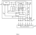
- the power tool 300 includes a power module, an output unit (not shown in the figure), a cell 312, a direct current interface 320, and a two-way control module 340.
- the powre tool 300 is a hand-held power tool such as an electric drill, a screwdriver, a nail gun, a wrench, and an angle grinder.
- a hand-held power tool such as an electric drill, a screwdriver, a nail gun, a wrench, and an angle grinder.
- this embodiment relates to a hand-held power tool, it is to be understood that the present application is not limited to the disclosed embodiment and can be applied to other types of power tools, including but not limited to garden power tools such as a vehicle-type lawn mower and a hair dryer.
- the power module includes a motor 311 and the cell 312.
- the motor 311 may be powered by the cell 312 or an external power supply device.
- the motor 311 is configured to drive the output unit to output power to an outside.
- an output mechanism is an output shaft driven by the motor.
- the cell 312 is configured to store power and can be repeatedly charged and discharged; the cell 312 may be a lithium-ion battery or a graphene battery.
- the direct current interface 320 is configured to be capable of being selectively connected to an external power consumption device or an external power supply device. In the case where the direct current interface 320 is in a charge state, electric power from the external power supply device is received; and in the case where the direct current interface 320 is in a discharge state, electric power of the cell 312 is supplied to the external power consumption device.
- the direct current interface 320 includes a detection terminal 323 and an electric power terminal, where the electric power terminal is configured to output or input electric power.
- the electric power terminal of the direct current interface 320 includes at least two power positive terminals. Two power positive terminals are a first electric power terminal 321 and a second electric power terminal 322, respectively, such as Vbus1 and Vbus2.
- the first electric power terminal 321 and the second electric power terminal 322 can be connected to a positive terminal of the external power consumption device or a positive terminal of the external power supply device and are configured to input or output electric power.
- the output or input power of the direct current interface is P, where P ⁇ 100 W; or 100 W ⁇ P ⁇ 200 W; or 200 W ⁇ P ⁇ 500 W.
- the output or input voltage of the direct current interface is U, where U ⁇ 20 V; or 20 V ⁇ U ⁇ 60 V; 60 V ⁇ U ⁇ 100V.
- the direct current interface 320 further includes the detection terminal 323 such as CC1; the detection terminal 323 detects a state signal of the direct current interface 320.
- the detection terminal 323 is configured to detect the state signal of the direct current interface 320, where the direct current interface 320 has the charge state, the discharge state, and an empty state.
- the detection terminal 323 detects a high level, the external power supply device is equivalent to a pull-up resistor, it is determined that the direct current interface 320 is a power supply side, the cell 312 is equivalent to a pull-down resistor and determined as a power receiving side, and the detection terminal 323 determines that the direct current interface 320 is in the charge state and sends a charge control signal to the two-way control module 330 so that the external power supply device charges the cell 312.
- the detection terminal 323 detects a low level, the external power consumption device is equivalent to a pull-down resistor, it is determined that the direct current interface 320 is a power receiving side, the cell 312 is equivalent to a pull-up resistor and determined as a power supply side, and the detection terminal 323 determines that the direct current interface 320 is in the discharge state and sends a discharge control signal to the two-way control module 330 so that the cell 312 is discharged to supply power to the external power consumption device.
- the two-way control module 330 is connected in series between the power module 310 and the direct current interface 320, where the two-way control module is configured to adjust electric power of the external power supply device according to a control signal of the direct current interface 320 to form an electric power input adapted to the cell 312 so that the external power supply device charges the cell 312; or the two-way control module is configured to adjust the electric power of the external power supply device according to a signal of the motor 311 to form an electric power input adapted to the motor 311 so that the external power supply device supplies power to the motor 311; the two-way control module 330 may also be configured to match a discharge voltage of the cell 312 with a power supply voltage required by the external power consumption device according to the control signal of the direct current interface 320 so that the external power consumption device is powered.
- the two-way control module may be one circuit board or may be integrated by multiple circuit boards, which is not limited herein.
- the two-way control module in the present application includes a main controller 331, a two-way power supply controller 332, and a voltage conversion circuit 333 that are disposed on a circuit board.
- the detection terminal 323 detects a charge signal and determines that the direct current interface 320 is in the charge state, and the detection terminal 232 sends the charge control signal to the main controller 331.
- the main controller 331 outputs a control signal to the two-way power supply controller 332 according to the charge control signal; the two-way power supply controller 332 receives the control signal from the main controller 331 and outputs a power supply control signal to the voltage conversion circuit 333 to control a current direction of the voltage conversion circuit 333 and control the voltage conversion circuit 333 to adjust the electric power of the external power supply device to form an electric power output adapted to the cell 312 or the motor 311 so that the external power supply device supplies power to the cell 312 or the motor 311.
- the main controller 331 further includes a communication terminal communicatively connected to the motor, and the main controller 331 can receive a communication signal from the motor 311 to send power supply information adapted to the motor 311 to the main controller 331, such as voltage and current information; the main controller 331 sends the control signal to the two-way power supply controller 332 according to the power supply information, and finally, the two-way power supply controller 332 outputs the power supply control signal to the voltage conversion circuit 333 to adjust electric power input by the external power supply device to the motor 311.
- a communication signal from the motor 311 to send power supply information adapted to the motor 311 to the main controller 331, such as voltage and current information
- the main controller 331 sends the control signal to the two-way power supply controller 332 according to the power supply information
- the two-way power supply controller 332 outputs the power supply control signal to the voltage conversion circuit 333 to adjust electric power input by the external power supply device to the motor 311.
- the detection terminal 323 detects a discharge signal and determines that the direct current interface 320 is in the discharge state, the detection terminal 323 sends the discharge control signal to the main controller 331, and the main controller 331 outputs the control signal to the two-way power supply controller 332 according to the discharge control signal.
- the two-way power supply controller 332 receives the control signal and controls the current direction of the voltage conversion circuit 333, and the voltage conversion circuit 333 matches the discharge voltage of the cell 312 with the power supply voltage required by the external power consumption device so that the external power consumption device is powered.
- an external power supply device of a smartphone or a laptop available on site may be used to charge the battery pack 100 through the direct current interface, and the battery pack 100 may also output the electric power stored in the cell to supply power to an external power consumption device such as the smartphone or the laptop.
- the power supply includes a case where electric power is directly supplied to the external power consumption device for its use and a case where the external power consumption device is charged.
- the power tool may be connected to the external power supply device or the external power consumption device through an adapter, and the adapter can make the battery pack output electric power and can also supply electric power to charge the power tool and/or the cell.
- the adapter may include a power plug and an output interface; of course, the adapter may also include an input interface and an output interface that are configured to be connected to the power tool and the external power supply device or the external power consumption device, respectively.
- the main controller 331 receives a signal from the communication terminal of the motor 311, the external power supply device supplies power to the motor 311 through the two-way control module, and the external power supply module may also charge the cell 312 through the two-way control module 330.
- the external power supply module may also charge the cell 312 through the two-way control module 330.
- the external power supply device may be configured to only supply power to the motor or only charge the cell.
- the preceding configuration may be implemented by a predetermined program set on the main controller 331.
- the cell 312 supplies power to the external power consumption device through the two-way control module 330; and the cell 312 may also supply power to the motor, and the power tool 300 can operate normally.
- the cell 312 supplies power to the motor 311, and the power tool can operate normally.
- the power tool in the present application is provided with the direct current interface and the two-way control module, which expands the use of the power tool and is convenient for a user to use. It is to be understood that since a design circuit architecture of the two-way power supply controller is adopted in the power tool, the charge and discharge control can be achieved through the same controller, which reduces the introduction of other operational amplifier circuits and simplifies the circuit structure.
Landscapes
- Engineering & Computer Science (AREA)
- General Engineering & Computer Science (AREA)
- Power Engineering (AREA)
- Mechanical Engineering (AREA)
- Charge And Discharge Circuits For Batteries Or The Like (AREA)
- Secondary Cells (AREA)
Claims (10)
- Elektrowerkzeug (300), umfassend:ein Leistungsmodul (310), das einen Motor (311) umfasst, wobei der Motor (311) so konfiguriert ist, dass er eine Ausgabeeinheit antreibt, um Leistung nach außen abzugeben;eine Gleichstromschnittstelle (320), die so ausgelegt ist, dass sie mit einer externen Stromversorgungsvorrichtung verbunden werden kann; undein Zweiwege-Steuermodul (330), das in Reihe zwischen der Gleichstromschnittstelle (320) und dem Leistungsmodul (310) geschaltet ist, wobei das Zwei-Wege-Steuermodul (330) so eingerichtet ist, dass es die elektrische Leistung der externen Stromversorgungseinrichtung entsprechend einem Steuersignal (323) der Gleichstromschnittstelle (320) einstellt, um eine an eine Zelle (312) und/oder den Motor (311) angepasste elektrische Leistungsaufnahme zu bilden, wenn die Gleichstromschnittstelle (320) mit der externen Stromversorgungseinrichtung verbunden ist, sodass die externe Stromversorgungseinrichtung die Zelle (312) und/oder den Motor (311) mit Strom versorgt, wobei die Zelle (312) elektrischen Strom an den Motor (311) liefert;dadurch gekennzeichnet, dassdas genannte Leistungsmodul (310) die genannte Zelle (312) umfasst;die Gleichstromschnittstelle (320) ist so konfiguriert, dass sie selektiv mit der externen Stromversorgungseinrichtung oder einer externen Stromverbrauchseinrichtung verbunden werden kann;wobei das Zwei-Wege-Steuermodul (330) so ausgelegt ist, dass es eine Entladespannung der Zelle (312) an eine von der externen Stromverbrauchsvorrichtung benötigte Stromversorgungsspannung gemäß dem Steuersignal (323) der Gleichstromschnittstelle (320) anpasst, wenn die Gleichstromschnittstelle (320) mit der externen Stromverbrauchsvorrichtung verbunden ist, sodass die externe Stromverbrauchseinrichtung mit Strom versorgt wird.
- Elektrowerkzeug (300) nach Anspruch 1, wobei
das Zwei-Wege-Steuermodul (330) Folgendes umfasst:eine Spannungswandlerschaltung (333), die mit der Gleichstromschnittstelle (320) verbunden ist,wobei die Spannungswandlerschaltung (333) so ausgelegt ist, dass sie die elektrische Leistung der externen Stromversorgungseinrichtung in die an die Zelle (312) und/oder den Motor (311) angepasste elektrische Leistungsaufnahme umwandelt; oder die Spannungswandlerschaltung (333) ist so ausgelegt, dass sie eine elektrische Leistung der Zelle (312) in eine elektrische Leistung umwandelt, die an die externe Stromverbrauchseinrichtung angepasst ist;einen Hauptcontroller (331), der mit der Gleichstromschnittstelle (320) verbunden ist, wobei der Hauptcontroller (331) so konfiguriert ist, dass er ein Steuersignal (323) an einen Zweiwege-Stromversorgungscontroller (332) entsprechend einem Zustandssignal der Gleichstromschnittstelle (320) ausgibt; undder Zweiwege-Stromversorgungsregler (332), der mit der Spannungswandlerschaltung (333) bzw. dem Hauptcontroller (331) verbunden ist, wobei der Zweiwege-Stromversorgungsregler (332) so konfiguriert ist, dass er eine Stromrichtung und eine Ausgangsspannung der Spannungswandlerschaltung (333) entsprechend dem Steuersignal (323) des Hauptcontrollers (331) steuert, sodass die externe Stromversorgungseinrichtung die Zelle (312) und/oder den Motor (311) mit Strom versorgt oder die Zelle (312) entladen wird, um die externe Stromverbrauchseinrichtung mit Strom zu versorgen. - Elektrowerkzeug (300) nach Anspruch 2, wobei der Hauptcontroller (331) ferner einen Kommunikationsanschluss umfasst, der mit dem Motor (311) kommunikativ verbunden ist, und der Hauptcontroller (331) steuert die Stromrichtung der Spannungswandlerschaltung (333) entsprechend der Kommunikationsinformationen des Motors (311), sodass die externe Stromversorgungseinrichtung den Motor (311) mit Strom versorgt.
- Elektrowerkzeug (300) nach Anspruch 2, wobei die Gleichstromschnittstelle (320) einen Erfassungsanschluss (323) und einen elektrischen Leistungsanschluss (321, 322) umfasst, wobei der Erfassungsanschluss das Zustandssignal der Gleichstromschnittstelle (320) erfasst, und der Stromanschluss ist so konfiguriert, dass er elektrischen Strom abgibt oder einspeist.
- Elektrowerkzeug (300) nach Anspruch 4, wobei der elektrische Leistungsanschluss mindestens zwei positive Leistungsanschlüsse (321, 322) umfasst, wobei die mindestens zwei positiven Stromanschlüsse mit einer positiven Elektrode der externen Stromverbrauchseinrichtung oder einer positiven Elektrode der externen Stromversorgungseinrichtung verbunden sind.
- Elektrowerkzeug (300) nach Anspruch 4, wobei das Zustandssignal mindestens ein Ladesignal und ein Entladesignal umfasst.
- Elektrowerkzeug (300) nach Anspruch 6, wobei in einem Fall, in dem die Gleichstromschnittstelle (320) mit der externen Stromversorgungseinrichtung verbunden ist, der Erfassungsanschluss das Ladesignal der Gleichstromschnittstelle (320) erfasst und ein Ladesteuersignal (323) an den Hauptcontroller (331) sendet, sodass der Hauptcontroller (331) die Stromrichtung der Spannungswandlerschaltung (333) steuert und so das externe Stromversorgungsgerät die Zelle (312) auflädt.
- Elektrowerkzeug (300) nach Anspruch 7, wobei in einem Fall, in dem die Erfassungsklemme einen hohen Pegel erfasst, festgelegt wird, dass die Gleichstromschnittstelle (320) das Ladesignal empfängt.
- Elektrowerkzeug (300) nach Anspruch 6, wobei in einem Fall, in dem die Gleichstromschnittstelle (320) mit der externen Stromverbrauchseinrichtung verbunden ist, die Erfassungsklemme das Entladesignal der Gleichstromschnittstelle (320) erfasst und ein Entladesteuersignal (323) an den Hauptcontroller (331) sendet, sodass der Hauptcontroller (331) die Stromrichtung der Spannungswandlerschaltung (333) steuert, und so wird die Zelle (312) entladen, um das externe Stromverbrauchsgerät mit Strom zu versorgen.
- Elektrowerkzeug (300) nach Anspruch 9, wobei in einem Fall, in dem die Erfassungsklemme einen niedrigen Pegel feststellt, festgelegt wird, dass die Gleichstromschnittstelle (320) das Entladesignal erhält.
Applications Claiming Priority (2)
| Application Number | Priority Date | Filing Date | Title |
|---|---|---|---|
| CN202010076760 | 2020-01-23 | ||
| PCT/CN2020/136005 WO2021147564A1 (zh) | 2020-01-23 | 2020-12-14 | 工具灯、电池包与工具灯的组合以及电动工具 |
Publications (3)
| Publication Number | Publication Date |
|---|---|
| EP3971472A1 EP3971472A1 (de) | 2022-03-23 |
| EP3971472A4 EP3971472A4 (de) | 2022-11-02 |
| EP3971472B1 true EP3971472B1 (de) | 2024-10-02 |
Family
ID=76991802
Family Applications (1)
| Application Number | Title | Priority Date | Filing Date |
|---|---|---|---|
| EP20915320.4A Active EP3971472B1 (de) | 2020-01-23 | 2020-12-14 | Nutzlicht, kombination aus batteriepack und nutzlicht und elektrowerkzeug |
Country Status (2)
| Country | Link |
|---|---|
| EP (1) | EP3971472B1 (de) |
| WO (1) | WO2021147564A1 (de) |
Families Citing this family (1)
| Publication number | Priority date | Publication date | Assignee | Title |
|---|---|---|---|---|
| CN120691523A (zh) * | 2024-03-22 | 2025-09-23 | 台达电子工业股份有限公司 | 电动工具及电源管理电路 |
Citations (1)
| Publication number | Priority date | Publication date | Assignee | Title |
|---|---|---|---|---|
| CN204497813U (zh) * | 2015-04-27 | 2015-07-22 | 黄永林 | 一种电动工具的电池包 |
Family Cites Families (8)
| Publication number | Priority date | Publication date | Assignee | Title |
|---|---|---|---|---|
| JP4104648B1 (ja) * | 2007-09-13 | 2008-06-18 | 和征 榊原 | 電池パック |
| CN101929607A (zh) * | 2009-06-25 | 2010-12-29 | 海洋王照明科技股份有限公司 | 便携式强光灯 |
| US9293947B2 (en) * | 2012-10-09 | 2016-03-22 | Tai-Her Yang | Lighting device having uninterruptible illumination and external power supply function |
| CN204131178U (zh) * | 2014-10-13 | 2015-01-28 | 深圳市永强科技有限公司 | 便携式移动电源 |
| CN104613402A (zh) * | 2015-02-03 | 2015-05-13 | 深圳市中孚能电气设备有限公司 | 一种无绳led灯 |
| CN107150315B (zh) * | 2016-03-04 | 2020-04-07 | 南京德朔实业有限公司 | 电动工具 |
| CN208890421U (zh) * | 2018-09-28 | 2019-05-21 | 深圳和而泰智能控制股份有限公司 | 一种电动工具 |
| CN110649680A (zh) * | 2019-10-26 | 2020-01-03 | 深圳市阿尓法智慧科技有限公司 | 一种双端供电的多用移动电源电路 |
-
2020
- 2020-12-14 WO PCT/CN2020/136005 patent/WO2021147564A1/zh not_active Ceased
- 2020-12-14 EP EP20915320.4A patent/EP3971472B1/de active Active
Patent Citations (1)
| Publication number | Priority date | Publication date | Assignee | Title |
|---|---|---|---|---|
| CN204497813U (zh) * | 2015-04-27 | 2015-07-22 | 黄永林 | 一种电动工具的电池包 |
Also Published As
| Publication number | Publication date |
|---|---|
| EP3971472A4 (de) | 2022-11-02 |
| EP3971472A1 (de) | 2022-03-23 |
| WO2021147564A1 (zh) | 2021-07-29 |
Similar Documents
| Publication | Publication Date | Title |
|---|---|---|
| US12341164B2 (en) | Electric energy storage device, power tool system and charging system | |
| US7017055B1 (en) | Hub that can supply power actively | |
| CN112087014B (zh) | 电池包与适配器的组合 | |
| US20080185915A1 (en) | Ups having solar powered battery charger | |
| EP4236020B1 (de) | Adapter und batteriepack sowie adapterkombination | |
| US20250266701A1 (en) | Adapter and combination of a battery pack and an adapter | |
| US20170331305A1 (en) | Adapter, power supply device, and over-discharge protection method | |
| US20100097032A1 (en) | Charging device and portable electronic device employing the same | |
| US8344702B2 (en) | Battery having universal serial bus port | |
| EP3971472B1 (de) | Nutzlicht, kombination aus batteriepack und nutzlicht und elektrowerkzeug | |
| TWI554000B (zh) | 行動充放電裝置 | |
| CN204597567U (zh) | 一种多功能无线充电设备 | |
| US20040174140A1 (en) | Charging device with two-way input/output from the battery holder | |
| US20050194928A1 (en) | Power tool capable of charging a rechargeable battery unit that includes at least a standard-sized battery cell | |
| CN102201154A (zh) | 一种用于演示的无线控制装置 | |
| US20150372521A1 (en) | Portable Power Bank | |
| AU2022228178A1 (en) | Charging device and control method therefor | |
| CN212909030U (zh) | 一种电源管理芯片及其应用电路及电子设备 | |
| KR20140126576A (ko) | 멀티 아답타기능과 다양한 휴대폰배터리를 활용한 멀티 충전기능 및 비리모콘 장치의 리모콘 방식 변환기능을 갖는 연결장치 | |
| CN218298827U (zh) | 玩具枪控制电路及玩具枪 | |
| CN205195360U (zh) | 模块化多功能三防移动电源 | |
| CN216086223U (zh) | 一种电动开盒控制电路 | |
| CN119482833A (zh) | 多功能移动电源及系统 | |
| CN202019472U (zh) | 太阳能路灯控制器 | |
| CN210297325U (zh) | 具有过充保护的充电显示电路 |
Legal Events
| Date | Code | Title | Description |
|---|---|---|---|
| STAA | Information on the status of an ep patent application or granted ep patent |
Free format text: STATUS: THE INTERNATIONAL PUBLICATION HAS BEEN MADE |
|
| PUAI | Public reference made under article 153(3) epc to a published international application that has entered the european phase |
Free format text: ORIGINAL CODE: 0009012 |
|
| STAA | Information on the status of an ep patent application or granted ep patent |
Free format text: STATUS: REQUEST FOR EXAMINATION WAS MADE |
|
| 17P | Request for examination filed |
Effective date: 20211216 |
|
| AK | Designated contracting states |
Kind code of ref document: A1 Designated state(s): AL AT BE BG CH CY CZ DE DK EE ES FI FR GB GR HR HU IE IS IT LI LT LU LV MC MK MT NL NO PL PT RO RS SE SI SK SM TR |
|
| A4 | Supplementary search report drawn up and despatched |
Effective date: 20220929 |
|
| RIC1 | Information provided on ipc code assigned before grant |
Ipc: F21L 4/08 20060101ALI20220923BHEP Ipc: F21L 4/00 20060101ALI20220923BHEP Ipc: H02J 7/00 20060101ALI20220923BHEP Ipc: B25F 5/00 20060101ALI20220923BHEP Ipc: F21V 23/00 20150101AFI20220923BHEP |
|
| DAV | Request for validation of the european patent (deleted) | ||
| DAX | Request for extension of the european patent (deleted) | ||
| STAA | Information on the status of an ep patent application or granted ep patent |
Free format text: STATUS: EXAMINATION IS IN PROGRESS |
|
| 17Q | First examination report despatched |
Effective date: 20230614 |
|
| GRAP | Despatch of communication of intention to grant a patent |
Free format text: ORIGINAL CODE: EPIDOSNIGR1 |
|
| STAA | Information on the status of an ep patent application or granted ep patent |
Free format text: STATUS: GRANT OF PATENT IS INTENDED |
|
| GRAS | Grant fee paid |
Free format text: ORIGINAL CODE: EPIDOSNIGR3 |
|
| GRAA | (expected) grant |
Free format text: ORIGINAL CODE: 0009210 |
|
| STAA | Information on the status of an ep patent application or granted ep patent |
Free format text: STATUS: THE PATENT HAS BEEN GRANTED |
|
| INTG | Intention to grant announced |
Effective date: 20240801 |
|
| AK | Designated contracting states |
Kind code of ref document: B1 Designated state(s): AL AT BE BG CH CY CZ DE DK EE ES FI FR GB GR HR HU IE IS IT LI LT LU LV MC MK MT NL NO PL PT RO RS SE SI SK SM TR |
|
| REG | Reference to a national code |
Ref country code: GB Ref legal event code: FG4D |
|
| REG | Reference to a national code |
Ref country code: CH Ref legal event code: EP |
|
| REG | Reference to a national code |
Ref country code: DE Ref legal event code: R096 Ref document number: 602020038860 Country of ref document: DE |
|
| REG | Reference to a national code |
Ref country code: IE Ref legal event code: FG4D |
|
| PGFP | Annual fee paid to national office [announced via postgrant information from national office to epo] |
Ref country code: DE Payment date: 20241029 Year of fee payment: 5 |
|
| PGFP | Annual fee paid to national office [announced via postgrant information from national office to epo] |
Ref country code: GB Payment date: 20241104 Year of fee payment: 5 |
|
| PGFP | Annual fee paid to national office [announced via postgrant information from national office to epo] |
Ref country code: FR Payment date: 20241111 Year of fee payment: 5 |
|
| REG | Reference to a national code |
Ref country code: LT Ref legal event code: MG9D |
|
| REG | Reference to a national code |
Ref country code: NL Ref legal event code: MP Effective date: 20241002 |
|
| REG | Reference to a national code |
Ref country code: AT Ref legal event code: MK05 Ref document number: 1728748 Country of ref document: AT Kind code of ref document: T Effective date: 20241002 |
|
| PG25 | Lapsed in a contracting state [announced via postgrant information from national office to epo] |
Ref country code: NL Free format text: LAPSE BECAUSE OF FAILURE TO SUBMIT A TRANSLATION OF THE DESCRIPTION OR TO PAY THE FEE WITHIN THE PRESCRIBED TIME-LIMIT Effective date: 20241002 |
|
| PG25 | Lapsed in a contracting state [announced via postgrant information from national office to epo] |
Ref country code: NL Free format text: LAPSE BECAUSE OF FAILURE TO SUBMIT A TRANSLATION OF THE DESCRIPTION OR TO PAY THE FEE WITHIN THE PRESCRIBED TIME-LIMIT Effective date: 20241002 |
|
| PG25 | Lapsed in a contracting state [announced via postgrant information from national office to epo] |
Ref country code: PT Free format text: LAPSE BECAUSE OF FAILURE TO SUBMIT A TRANSLATION OF THE DESCRIPTION OR TO PAY THE FEE WITHIN THE PRESCRIBED TIME-LIMIT Effective date: 20250203 Ref country code: IS Free format text: LAPSE BECAUSE OF FAILURE TO SUBMIT A TRANSLATION OF THE DESCRIPTION OR TO PAY THE FEE WITHIN THE PRESCRIBED TIME-LIMIT Effective date: 20250202 Ref country code: HR Free format text: LAPSE BECAUSE OF FAILURE TO SUBMIT A TRANSLATION OF THE DESCRIPTION OR TO PAY THE FEE WITHIN THE PRESCRIBED TIME-LIMIT Effective date: 20241002 |
|
| PG25 | Lapsed in a contracting state [announced via postgrant information from national office to epo] |
Ref country code: FI Free format text: LAPSE BECAUSE OF FAILURE TO SUBMIT A TRANSLATION OF THE DESCRIPTION OR TO PAY THE FEE WITHIN THE PRESCRIBED TIME-LIMIT Effective date: 20241002 |
|
| PG25 | Lapsed in a contracting state [announced via postgrant information from national office to epo] |
Ref country code: BG Free format text: LAPSE BECAUSE OF FAILURE TO SUBMIT A TRANSLATION OF THE DESCRIPTION OR TO PAY THE FEE WITHIN THE PRESCRIBED TIME-LIMIT Effective date: 20241002 |
|
| PG25 | Lapsed in a contracting state [announced via postgrant information from national office to epo] |
Ref country code: ES Free format text: LAPSE BECAUSE OF FAILURE TO SUBMIT A TRANSLATION OF THE DESCRIPTION OR TO PAY THE FEE WITHIN THE PRESCRIBED TIME-LIMIT Effective date: 20241002 |
|
| PG25 | Lapsed in a contracting state [announced via postgrant information from national office to epo] |
Ref country code: NO Free format text: LAPSE BECAUSE OF FAILURE TO SUBMIT A TRANSLATION OF THE DESCRIPTION OR TO PAY THE FEE WITHIN THE PRESCRIBED TIME-LIMIT Effective date: 20250102 |
|
| PG25 | Lapsed in a contracting state [announced via postgrant information from national office to epo] |
Ref country code: GR Free format text: LAPSE BECAUSE OF FAILURE TO SUBMIT A TRANSLATION OF THE DESCRIPTION OR TO PAY THE FEE WITHIN THE PRESCRIBED TIME-LIMIT Effective date: 20250103 Ref country code: LV Free format text: LAPSE BECAUSE OF FAILURE TO SUBMIT A TRANSLATION OF THE DESCRIPTION OR TO PAY THE FEE WITHIN THE PRESCRIBED TIME-LIMIT Effective date: 20241002 Ref country code: AT Free format text: LAPSE BECAUSE OF FAILURE TO SUBMIT A TRANSLATION OF THE DESCRIPTION OR TO PAY THE FEE WITHIN THE PRESCRIBED TIME-LIMIT Effective date: 20241002 |
|
| PG25 | Lapsed in a contracting state [announced via postgrant information from national office to epo] |
Ref country code: CZ Free format text: LAPSE BECAUSE OF FAILURE TO SUBMIT A TRANSLATION OF THE DESCRIPTION OR TO PAY THE FEE WITHIN THE PRESCRIBED TIME-LIMIT Effective date: 20241002 Ref country code: PL Free format text: LAPSE BECAUSE OF FAILURE TO SUBMIT A TRANSLATION OF THE DESCRIPTION OR TO PAY THE FEE WITHIN THE PRESCRIBED TIME-LIMIT Effective date: 20241002 |
|
| PG25 | Lapsed in a contracting state [announced via postgrant information from national office to epo] |
Ref country code: RS Free format text: LAPSE BECAUSE OF FAILURE TO SUBMIT A TRANSLATION OF THE DESCRIPTION OR TO PAY THE FEE WITHIN THE PRESCRIBED TIME-LIMIT Effective date: 20250102 |
|
| PG25 | Lapsed in a contracting state [announced via postgrant information from national office to epo] |
Ref country code: SM Free format text: LAPSE BECAUSE OF FAILURE TO SUBMIT A TRANSLATION OF THE DESCRIPTION OR TO PAY THE FEE WITHIN THE PRESCRIBED TIME-LIMIT Effective date: 20241002 |
|
| REG | Reference to a national code |
Ref country code: DE Ref legal event code: R097 Ref document number: 602020038860 Country of ref document: DE |
|
| PG25 | Lapsed in a contracting state [announced via postgrant information from national office to epo] |
Ref country code: MC Free format text: LAPSE BECAUSE OF FAILURE TO SUBMIT A TRANSLATION OF THE DESCRIPTION OR TO PAY THE FEE WITHIN THE PRESCRIBED TIME-LIMIT Effective date: 20241002 |
|
| PG25 | Lapsed in a contracting state [announced via postgrant information from national office to epo] |
Ref country code: DK Free format text: LAPSE BECAUSE OF FAILURE TO SUBMIT A TRANSLATION OF THE DESCRIPTION OR TO PAY THE FEE WITHIN THE PRESCRIBED TIME-LIMIT Effective date: 20241002 |
|
| PG25 | Lapsed in a contracting state [announced via postgrant information from national office to epo] |
Ref country code: EE Free format text: LAPSE BECAUSE OF FAILURE TO SUBMIT A TRANSLATION OF THE DESCRIPTION OR TO PAY THE FEE WITHIN THE PRESCRIBED TIME-LIMIT Effective date: 20241002 |
|
| PG25 | Lapsed in a contracting state [announced via postgrant information from national office to epo] |
Ref country code: RO Free format text: LAPSE BECAUSE OF FAILURE TO SUBMIT A TRANSLATION OF THE DESCRIPTION OR TO PAY THE FEE WITHIN THE PRESCRIBED TIME-LIMIT Effective date: 20241002 |
|
| PG25 | Lapsed in a contracting state [announced via postgrant information from national office to epo] |
Ref country code: SK Free format text: LAPSE BECAUSE OF FAILURE TO SUBMIT A TRANSLATION OF THE DESCRIPTION OR TO PAY THE FEE WITHIN THE PRESCRIBED TIME-LIMIT Effective date: 20241002 |
|
| PG25 | Lapsed in a contracting state [announced via postgrant information from national office to epo] |
Ref country code: IT Free format text: LAPSE BECAUSE OF FAILURE TO SUBMIT A TRANSLATION OF THE DESCRIPTION OR TO PAY THE FEE WITHIN THE PRESCRIBED TIME-LIMIT Effective date: 20241002 |
|
| REG | Reference to a national code |
Ref country code: CH Ref legal event code: PL |
|
| PLBE | No opposition filed within time limit |
Free format text: ORIGINAL CODE: 0009261 |
|
| STAA | Information on the status of an ep patent application or granted ep patent |
Free format text: STATUS: NO OPPOSITION FILED WITHIN TIME LIMIT |
|
| PG25 | Lapsed in a contracting state [announced via postgrant information from national office to epo] |
Ref country code: LU Free format text: LAPSE BECAUSE OF NON-PAYMENT OF DUE FEES Effective date: 20241214 |
|
| PG25 | Lapsed in a contracting state [announced via postgrant information from national office to epo] |
Ref country code: SE Free format text: LAPSE BECAUSE OF FAILURE TO SUBMIT A TRANSLATION OF THE DESCRIPTION OR TO PAY THE FEE WITHIN THE PRESCRIBED TIME-LIMIT Effective date: 20241002 |
|
| 26N | No opposition filed |
Effective date: 20250703 |
|
| REG | Reference to a national code |
Ref country code: BE Ref legal event code: MM Effective date: 20241231 |
|
| PG25 | Lapsed in a contracting state [announced via postgrant information from national office to epo] |
Ref country code: BE Free format text: LAPSE BECAUSE OF NON-PAYMENT OF DUE FEES Effective date: 20241231 |
|
| PG25 | Lapsed in a contracting state [announced via postgrant information from national office to epo] |
Ref country code: CH Free format text: LAPSE BECAUSE OF NON-PAYMENT OF DUE FEES Effective date: 20241231 |
|
| PG25 | Lapsed in a contracting state [announced via postgrant information from national office to epo] |
Ref country code: IE Free format text: LAPSE BECAUSE OF NON-PAYMENT OF DUE FEES Effective date: 20241214 |