EP3288147B1 - Elektrisches werkzeug und steuerungsverfahren dafür - Google Patents
Elektrisches werkzeug und steuerungsverfahren dafür Download PDFInfo
- Publication number
- EP3288147B1 EP3288147B1 EP16802586.4A EP16802586A EP3288147B1 EP 3288147 B1 EP3288147 B1 EP 3288147B1 EP 16802586 A EP16802586 A EP 16802586A EP 3288147 B1 EP3288147 B1 EP 3288147B1
- Authority
- EP
- European Patent Office
- Prior art keywords
- battery pack
- battery
- switch device
- voltage
- switch
- Prior art date
- Legal status (The legal status is an assumption and is not a legal conclusion. Google has not performed a legal analysis and makes no representation as to the accuracy of the status listed.)
- Active
Links
Images


Classifications
-
- H—ELECTRICITY
- H02—GENERATION; CONVERSION OR DISTRIBUTION OF ELECTRIC POWER
- H02J—ELECTRIC POWER NETWORKS; CIRCUIT ARRANGEMENTS OR SYSTEMS FOR SUPPLYING OR DISTRIBUTING ELECTRIC POWER; SYSTEMS FOR STORING ELECTRIC ENERGY
- H02J7/00—Circuit arrangements for charging or discharging batteries or for supplying loads from batteries
- H02J7/50—Circuit arrangements for charging or discharging batteries or for supplying loads from batteries acting upon multiple batteries simultaneously or sequentially
-
- A—HUMAN NECESSITIES
- A01—AGRICULTURE; FORESTRY; ANIMAL HUSBANDRY; HUNTING; TRAPPING; FISHING
- A01D—HARVESTING; MOWING
- A01D34/00—Mowers; Mowing apparatus of harvesters
- A01D34/001—Accessories not otherwise provided for
-
- A—HUMAN NECESSITIES
- A01—AGRICULTURE; FORESTRY; ANIMAL HUSBANDRY; HUNTING; TRAPPING; FISHING
- A01D—HARVESTING; MOWING
- A01D34/00—Mowers; Mowing apparatus of harvesters
- A01D34/006—Control or measuring arrangements
-
- A—HUMAN NECESSITIES
- A01—AGRICULTURE; FORESTRY; ANIMAL HUSBANDRY; HUNTING; TRAPPING; FISHING
- A01D—HARVESTING; MOWING
- A01D69/00—Driving mechanisms or parts thereof for harvesters or mowers
- A01D69/02—Driving mechanisms or parts thereof for harvesters or mowers electric
-
- G—PHYSICS
- G01—MEASURING; TESTING
- G01R—MEASURING ELECTRIC VARIABLES; MEASURING MAGNETIC VARIABLES
- G01R31/00—Arrangements for testing electric properties; Arrangements for locating electric faults; Arrangements for electrical testing characterised by what is being tested not provided for elsewhere
- G01R31/36—Arrangements for testing, measuring or monitoring the electrical condition of accumulators or electric batteries, e.g. capacity or state of charge [SoC]
- G01R31/382—Arrangements for monitoring battery or accumulator variables, e.g. SoC
- G01R31/3835—Arrangements for monitoring battery or accumulator variables, e.g. SoC involving only voltage measurements
-
- H—ELECTRICITY
- H01—ELECTRIC ELEMENTS
- H01M—PROCESSES OR MEANS, e.g. BATTERIES, FOR THE DIRECT CONVERSION OF CHEMICAL ENERGY INTO ELECTRICAL ENERGY
- H01M10/00—Secondary cells; Manufacture thereof
- H01M10/42—Methods or arrangements for servicing or maintenance of secondary cells or secondary half-cells
- H01M10/4207—Methods or arrangements for servicing or maintenance of secondary cells or secondary half-cells for several batteries or cells simultaneously or sequentially
-
- H—ELECTRICITY
- H01—ELECTRIC ELEMENTS
- H01M—PROCESSES OR MEANS, e.g. BATTERIES, FOR THE DIRECT CONVERSION OF CHEMICAL ENERGY INTO ELECTRICAL ENERGY
- H01M10/00—Secondary cells; Manufacture thereof
- H01M10/42—Methods or arrangements for servicing or maintenance of secondary cells or secondary half-cells
- H01M10/425—Structural combination with electronic components, e.g. electronic circuits integrated to the outside of the casing
-
- H—ELECTRICITY
- H01—ELECTRIC ELEMENTS
- H01M—PROCESSES OR MEANS, e.g. BATTERIES, FOR THE DIRECT CONVERSION OF CHEMICAL ENERGY INTO ELECTRICAL ENERGY
- H01M10/00—Secondary cells; Manufacture thereof
- H01M10/42—Methods or arrangements for servicing or maintenance of secondary cells or secondary half-cells
- H01M10/48—Accumulators combined with arrangements for measuring, testing or indicating the condition of cells, e.g. the level or density of the electrolyte
-
- H—ELECTRICITY
- H01—ELECTRIC ELEMENTS
- H01M—PROCESSES OR MEANS, e.g. BATTERIES, FOR THE DIRECT CONVERSION OF CHEMICAL ENERGY INTO ELECTRICAL ENERGY
- H01M50/00—Constructional details or processes of manufacture of the non-active parts of electrochemical cells other than fuel cells, e.g. hybrid cells
- H01M50/20—Mountings; Secondary casings or frames; Racks, modules or packs; Suspension devices; Shock absorbers; Transport or carrying devices; Holders
- H01M50/202—Casings or frames around the primary casing of a single cell or a single battery
-
- H—ELECTRICITY
- H01—ELECTRIC ELEMENTS
- H01M—PROCESSES OR MEANS, e.g. BATTERIES, FOR THE DIRECT CONVERSION OF CHEMICAL ENERGY INTO ELECTRICAL ENERGY
- H01M50/00—Constructional details or processes of manufacture of the non-active parts of electrochemical cells other than fuel cells, e.g. hybrid cells
- H01M50/20—Mountings; Secondary casings or frames; Racks, modules or packs; Suspension devices; Shock absorbers; Transport or carrying devices; Holders
- H01M50/247—Mountings; Secondary casings or frames; Racks, modules or packs; Suspension devices; Shock absorbers; Transport or carrying devices; Holders specially adapted for portable devices, e.g. mobile phones, computers, hand tools or pacemakers
-
- H—ELECTRICITY
- H01—ELECTRIC ELEMENTS
- H01M—PROCESSES OR MEANS, e.g. BATTERIES, FOR THE DIRECT CONVERSION OF CHEMICAL ENERGY INTO ELECTRICAL ENERGY
- H01M50/00—Constructional details or processes of manufacture of the non-active parts of electrochemical cells other than fuel cells, e.g. hybrid cells
- H01M50/20—Mountings; Secondary casings or frames; Racks, modules or packs; Suspension devices; Shock absorbers; Transport or carrying devices; Holders
- H01M50/296—Mountings; Secondary casings or frames; Racks, modules or packs; Suspension devices; Shock absorbers; Transport or carrying devices; Holders characterised by terminals of battery packs
-
- H—ELECTRICITY
- H01—ELECTRIC ELEMENTS
- H01M—PROCESSES OR MEANS, e.g. BATTERIES, FOR THE DIRECT CONVERSION OF CHEMICAL ENERGY INTO ELECTRICAL ENERGY
- H01M50/00—Constructional details or processes of manufacture of the non-active parts of electrochemical cells other than fuel cells, e.g. hybrid cells
- H01M50/50—Current conducting connections for cells or batteries
- H01M50/572—Means for preventing undesired use or discharge
- H01M50/574—Devices or arrangements for the interruption of current
-
- H—ELECTRICITY
- H02—GENERATION; CONVERSION OR DISTRIBUTION OF ELECTRIC POWER
- H02J—ELECTRIC POWER NETWORKS; CIRCUIT ARRANGEMENTS OR SYSTEMS FOR SUPPLYING OR DISTRIBUTING ELECTRIC POWER; SYSTEMS FOR STORING ELECTRIC ENERGY
- H02J7/00—Circuit arrangements for charging or discharging batteries or for supplying loads from batteries
- H02J7/34—Parallel operation in networks using both storage and other DC sources, e.g. providing buffering
-
- H—ELECTRICITY
- H02—GENERATION; CONVERSION OR DISTRIBUTION OF ELECTRIC POWER
- H02J—ELECTRIC POWER NETWORKS; CIRCUIT ARRANGEMENTS OR SYSTEMS FOR SUPPLYING OR DISTRIBUTING ELECTRIC POWER; SYSTEMS FOR STORING ELECTRIC ENERGY
- H02J7/00—Circuit arrangements for charging or discharging batteries or for supplying loads from batteries
- H02J7/36—Arrangements using end-cell switching
-
- H—ELECTRICITY
- H02—GENERATION; CONVERSION OR DISTRIBUTION OF ELECTRIC POWER
- H02J—ELECTRIC POWER NETWORKS; CIRCUIT ARRANGEMENTS OR SYSTEMS FOR SUPPLYING OR DISTRIBUTING ELECTRIC POWER; SYSTEMS FOR STORING ELECTRIC ENERGY
- H02J7/00—Circuit arrangements for charging or discharging batteries or for supplying loads from batteries
- H02J7/855—Circuit arrangements for charging or discharging batteries or for supplying loads from batteries with circuits adapted for supplying loads from the battery
-
- H—ELECTRICITY
- H02—GENERATION; CONVERSION OR DISTRIBUTION OF ELECTRIC POWER
- H02P—CONTROL OR REGULATION OF ELECTRIC MOTORS, ELECTRIC GENERATORS OR DYNAMO-ELECTRIC CONVERTERS; CONTROLLING TRANSFORMERS, REACTORS OR CHOKE COILS
- H02P7/00—Arrangements for regulating or controlling the speed or torque of electric DC motors
-
- A—HUMAN NECESSITIES
- A01—AGRICULTURE; FORESTRY; ANIMAL HUSBANDRY; HUNTING; TRAPPING; FISHING
- A01D—HARVESTING; MOWING
- A01D34/00—Mowers; Mowing apparatus of harvesters
- A01D34/01—Mowers; Mowing apparatus of harvesters characterised by features relating to the type of cutting apparatus
- A01D34/412—Mowers; Mowing apparatus of harvesters characterised by features relating to the type of cutting apparatus having rotating cutters
- A01D34/63—Mowers; Mowing apparatus of harvesters characterised by features relating to the type of cutting apparatus having rotating cutters having cutters rotating about a vertical axis
- A01D34/76—Driving mechanisms for the cutters
- A01D34/78—Driving mechanisms for the cutters electric
-
- G—PHYSICS
- G01—MEASURING; TESTING
- G01R—MEASURING ELECTRIC VARIABLES; MEASURING MAGNETIC VARIABLES
- G01R19/00—Arrangements for measuring currents or voltages or for indicating presence or sign thereof
- G01R19/165—Indicating that current or voltage is either above or below a predetermined value or within or outside a predetermined range of values
- G01R19/16533—Indicating that current or voltage is either above or below a predetermined value or within or outside a predetermined range of values characterised by the application
- G01R19/16538—Indicating that current or voltage is either above or below a predetermined value or within or outside a predetermined range of values characterised by the application in AC or DC supplies
- G01R19/16542—Indicating that current or voltage is either above or below a predetermined value or within or outside a predetermined range of values characterised by the application in AC or DC supplies for batteries
-
- H—ELECTRICITY
- H01—ELECTRIC ELEMENTS
- H01M—PROCESSES OR MEANS, e.g. BATTERIES, FOR THE DIRECT CONVERSION OF CHEMICAL ENERGY INTO ELECTRICAL ENERGY
- H01M10/00—Secondary cells; Manufacture thereof
- H01M10/05—Accumulators with non-aqueous electrolyte
- H01M10/052—Li-accumulators
- H01M10/0525—Rocking-chair batteries, i.e. batteries with lithium insertion or intercalation in both electrodes; Lithium-ion batteries
-
- H—ELECTRICITY
- H01—ELECTRIC ELEMENTS
- H01M—PROCESSES OR MEANS, e.g. BATTERIES, FOR THE DIRECT CONVERSION OF CHEMICAL ENERGY INTO ELECTRICAL ENERGY
- H01M2200/00—Safety devices for primary or secondary batteries
-
- H—ELECTRICITY
- H01—ELECTRIC ELEMENTS
- H01M—PROCESSES OR MEANS, e.g. BATTERIES, FOR THE DIRECT CONVERSION OF CHEMICAL ENERGY INTO ELECTRICAL ENERGY
- H01M2220/00—Batteries for particular applications
- H01M2220/30—Batteries in portable systems, e.g. mobile phone, laptop
-
- H—ELECTRICITY
- H02—GENERATION; CONVERSION OR DISTRIBUTION OF ELECTRIC POWER
- H02J—ELECTRIC POWER NETWORKS; CIRCUIT ARRANGEMENTS OR SYSTEMS FOR SUPPLYING OR DISTRIBUTING ELECTRIC POWER; SYSTEMS FOR STORING ELECTRIC ENERGY
- H02J7/00—Circuit arrangements for charging or discharging batteries or for supplying loads from batteries
- H02J7/50—Circuit arrangements for charging or discharging batteries or for supplying loads from batteries acting upon multiple batteries simultaneously or sequentially
- H02J7/585—Sequential battery discharge in systems with a plurality of batteries
-
- H—ELECTRICITY
- H02—GENERATION; CONVERSION OR DISTRIBUTION OF ELECTRIC POWER
- H02P—CONTROL OR REGULATION OF ELECTRIC MOTORS, ELECTRIC GENERATORS OR DYNAMO-ELECTRIC CONVERTERS; CONTROLLING TRANSFORMERS, REACTORS OR CHOKE COILS
- H02P7/00—Arrangements for regulating or controlling the speed or torque of electric DC motors
- H02P7/06—Arrangements for regulating or controlling the speed or torque of electric DC motors for regulating or controlling an individual DC dynamo-electric motor by varying field or armature current
- H02P7/18—Arrangements for regulating or controlling the speed or torque of electric DC motors for regulating or controlling an individual DC dynamo-electric motor by varying field or armature current by master control with auxiliary power
- H02P7/24—Arrangements for regulating or controlling the speed or torque of electric DC motors for regulating or controlling an individual DC dynamo-electric motor by varying field or armature current by master control with auxiliary power using discharge tubes or semiconductor devices
- H02P7/28—Arrangements for regulating or controlling the speed or torque of electric DC motors for regulating or controlling an individual DC dynamo-electric motor by varying field or armature current by master control with auxiliary power using discharge tubes or semiconductor devices using semiconductor devices
-
- Y—GENERAL TAGGING OF NEW TECHNOLOGICAL DEVELOPMENTS; GENERAL TAGGING OF CROSS-SECTIONAL TECHNOLOGIES SPANNING OVER SEVERAL SECTIONS OF THE IPC; TECHNICAL SUBJECTS COVERED BY FORMER USPC CROSS-REFERENCE ART COLLECTIONS [XRACs] AND DIGESTS
- Y02—TECHNOLOGIES OR APPLICATIONS FOR MITIGATION OR ADAPTATION AGAINST CLIMATE CHANGE
- Y02E—REDUCTION OF GREENHOUSE GAS [GHG] EMISSIONS, RELATED TO ENERGY GENERATION, TRANSMISSION OR DISTRIBUTION
- Y02E60/00—Enabling technologies; Technologies with a potential or indirect contribution to GHG emissions mitigation
- Y02E60/10—Energy storage using batteries
Definitions
- the present disclosure relates generally to power tools, and more particularly to lawn and garden power tools.
- a power tool such as mower is powered by high-capacity AC power source or a DC battery power source.
- Document US 2014/0265604 A1 discloses a power tool operable to receive a first battery pack and a second battery pack.
- the power tool includes a motor; a first switch; a second switch; and a controller.
- the controller is operable to monitor a first voltage of the first battery pack and a second voltage of the second battery pack, close the first switch and the second switch when the first voltage and the second voltage are within a predetermined range, open the first switch when the first voltage is outside of the predetermined range of the second voltage and the second voltage is greater than the first voltage, and open the second switch when the second voltage is outside of the predetermined range of the first voltage and the first voltage is greater than the second voltage.
- a power tool comprises a motor, a first battery pack having a first battery, a second battery pack having a second battery connected in parallel with the first battery, a first battery receptacle for receipt of the first battery pack, a second battery receptacle for receipt of the second battery pack, a first switch device connected between the first battery and the motor so as to form a first electrical connection between the first battery and the motor or cut off the first electrical connection between the first battery and the motor, a second switch device being connected between the second battery and the motor so as to form a second electrical connection between the second battery and the motor or cut off the second electrical connection between the second battery and the motor, and a controller characterised in that the controller is operable to: detect a first voltage drop across the first switch device from a respective high potential point to a respective low potential point; and control the first switch device to cut off the first electrical connection between the second battery and the motor when the first voltage drop is less than a first control voltage; detect a second voltage drop across the second switch device from
- the first control voltage value is greater than zero.
- the first switch device is a field effect transistor.
- the second switch device is a field effect transistor.
- first switch device is electrically connected to the second switch device such that the first battery pack and the second battery pack are connected in parallel when both of the first switch device and the second switch device are on.
- first battery pack and the second battery pack are lithium cell and have the same nominal voltage and the same battery pack interface.
- the power tool is mower which comprises a body, the first battery receptacle and the second battery receptacle are set in a line on the body.
- a power tool adapted to be connected with a plurality of battery packs each having a positive electrode and a negative electrode thereof and comprises: a plurality of battery receptacles each including a positive terminal for connecting the positive electrode of the battery pack and a positive node, and a negative terminal for connecting the negative electrode of the battery pack and a negative node; a plurality of switch devices adapted for the respective battery receptacles, each of the switch devices including a first switch terminal connectable with the negative node, and a second switch terminal connectable with the negative terminal of the battery receptacle; a motor connected between the positive node and the negative node; and a controller characterised in that the controller is operable to: detect a voltage drop between the first switch terminal and the second switch terminal of a respective switch device from a respective high potential point to a respective low potential point, and control the respective switch device so as to cut off the electrical connection between the first switch terminal and the second switch terminal when the voltage drop of the respective switch device is less
- the switch device is a field effect transistor
- first battery pack and the second battery pack are lithium cell and have the same nominal voltage and the same battery pack interface.
- a method of controlling a power tool with a plurality of battery packs each having a positive electrode and a negative electrode wherein the power tool comprises a plurality of battery receptacles each including a positive terminal for connecting the positive electrode of the battery pack and a positive node, and a negative terminal for connecting the negative electrode of the battery pack and a negative node; a plurality of switch devices each connected in series with the respective battery pack and the power tool, the switch device including a first switch terminal connected with the negative node and a second switch terminal connected with the negative terminal of the battery receptacle; a motor connected between the negative node and the positive node; and a controller for controlling the switch device and the motor, the method being characterised by including: closing the plurality of switch devices; detecting a voltage drop between the first switch terminal and the second switch terminal of each of the switch devices from a respective high potential point to a respective low potential point; judging whether the voltage drop across the respective switch device is less than a control voltage
- the predetermined value is greater than zero.
- the plurality of switch devices is connected in parallel, the plurality of battery packs are placed in a parallel configuration.
- the method comprises detecting a current voltage of a respective battery pack by the controller, interrupting the connection of the battery pack and the motor when the current voltage of the battery pack detected is less than a voltage threshold.
- first battery pack and the second battery pack are lithium cells with a same nominal voltage and as a same battery pack interface.
- a first battery pack 11 and a second battery pack 12 are used to power a power tool 13.
- the first battery pack 11 and a second battery pack 12 may be the same battery pack or not.
- the first battery pack 11 and the second battery pack 12 may also be combined for powering the additional power tool.
- the first battery pack 11 and the second battery pack 12 are lithium batteries or Li-ion batteries, and have a same nominal voltage and a same battery pack port.
- the first battery pack has a first battery
- the second battery pack has a second battery connected in parallel with the first battery.
- the first battery pack 11 includes a first positive pole 111, a battery 112 and a first negative pole 113.
- the first positive pole 111 connects to a positive pole of the battery 112 as a positive pole of the first battery pack 11 for outputting electric energy.
- the first negative pole 113 connects to a negative pole of the battery 112 as a negative pole of the first battery pack 11 for outputting electric energy.
- the battery 112 may be composed of a plurality of connected battery cells.
- the second battery pack 12 includes a second positive pole 121, a battery 122 and a second negative pole 123.
- the second positive pole 121 connects to a positive pole of the battery 122 as a positive pole of the second battery pack 12 for outputting electric energy.
- the second negative pole 123 connects to a negative pole of the battery 122 as a negative pole of the second battery pack 12 for outputting electric energy.
- the battery 122 may be composed of a plurality of connected battery cell.
- a power tool 13 comprises a first battery receptacle 101 for receipt of the first battery pack 11 and a second battery receptacle 102 for receipt of the second battery pack 12.
- the first battery receptacle 101 includes a first positive terminal 132 and a first negative terminal 133.
- the first positive terminal 132 connects to the first positive pole 111.
- the first negative terminal 133 connects to the first negative pole 113.
- the second battery receptacle 102 includes a second positive terminal 135 and a second negative terminal 136.
- the second positive terminal 135 connects to the second positive pole 121.
- the second negative terminal 136 connects to the second negative pole 123. Both of the first positive terminal 132 and the second positive terminal 135 to a positive node A. Both of the first negative terminal 133 and the second negative terminal 136 connect to a negative node B.
- the power tool 13 further comprises a first switch device 131, a second switch device 134, a motor 138 and a controller 139.
- the motor 138 connects between the positive node A and the negative node B.
- the first switch device 131 is connected between the first battery or battery pack and the motor so as to form a first electrical connection between the first battery and the motor or cut off the first electrical connection between the first battery and the motor, and the second switch device 134 is connected between the second battery or battery pack and the motor so as to form a second electrical connection between the second battery and the motor or cut off the second electrical connection between the second battery and the motor.
- the first switch device 131 is set between the positive node A and the positive terminal 132.
- a first switch terminal of the first switch device 131 connects to the positive node A
- a second switch terminal of the first switch device 131 connects to the first battery receptacle 101 or the positive terminal 132.
- the first switch device 131 is closed to form the electrical connection between the first battery or battery pack and the motor, or opened to cut off the electrical connection of the first battery or battery pack and the motor 138.
- the first switch device 131 includes one or more transistors such as MOSFETs or power MOSFETs. In one form, the first switch device 131 is a field effect transistor. In another form, the first switch device 13 is a circuit module with a similar switch function. The circuit module also has a first connection point or terminal for connecting to the positive node A and a second connection point or terminal for connecting to the first positive terminal 132.
- the second switch device 134 is set between the positive node A and second positive terminal 135.
- a first switch terminal of the second switch device 134 connects to the positive node A, and a second switch terminal of the second switch device 134 connects to the second battery receptacle 102 or the second positive terminal 135.
- the second switch device 134 is closed to form the electrical connection between the first battery or battery pack and the motor, or opened to cut off the electrical connection of the second battery or battery pack and the motor 138.
- the second switch device 134 includes one or more transistors such as MOSFETs or power MOSFETs.
- the second switch device 134 is a MOSFIELD EFFECT TRANSISTOR.
- the second switch device 134 is a circuit module with similar switch functions. The circuit module also has a first connection point or terminal for connecting to the positive node A and a second connection point or terminal for connecting to the second positive terminal 135.
- the second switch device 134 may use the same semiconductor element as the first switch device 131 or be a circuit module having similar switching functions.
- the first battery pack 11 and the second battery pack 12 plug in the power tool 13 respectively.
- the first positive pole 111 connects to the first positive terminal 132.
- the first negative pole 113 connects to the first negative terminal 133.
- the second positive pole 121 connects to the second positive terminal 135.
- the second negative pole 123 connects to the second negative terminal 136.
- the battery pack 11 and the battery pack 12 are set in parallel to supply power for the motor 138 when the switch 137 is closed.
- the voltage of the first positive terminal 132 is higher than that of the second positive terminal 135.
- the first switch device 131 and the second switch device 134 are MOSFET each with two connecting terminals and a control terminal.
- the two connecting terminals of the first switch device 131 are connected in series between the first positive terminal 132 and the positive node A. Turn off the first switch device 131, current from the first positive terminal 132 flows into the positive node A through the two connecting terminals of the first switch device 131.
- Controller 139a is set for detecting across the first switch device 131 a first voltage drop, which is defined by a potential or voltage drop between the first terminal and the second terminal of the first switch device 131 along the current direction, or between the positive node A and the first positive terminal 132 due to the connection of the first terminal to the positive node A and the connection of the second terminal to the first positive terminal 132.
- the first voltage drop of the first switch device 131 detected by the controller 139a along the current direction equals to the potential or voltage drop from a high potential point of the first positive terminal 132 to a low potential point of the positive node A.
- the controller 139a sends a signal to cause the first switch device 131 opened to disconnect the first battery pack 11 and the motor 138. That is, if the first voltage drop as detected from the high potential point of the first positive terminal 132 to the low potential point of the positive node A is less than the first control voltage, the controller 139a will control the first switch device 131 opened to cut off the electrical connection of the first battery or battery pack 11 and the motor 138.
- the first control voltage has a value greater than zero, and set for initiating the first switch device 131 and/or the controller 139a.
- the controller 139a enables the first switch device 131 closed to form the electrical connection of the first battery or battery pack 11 and the motor 138.
- Controller 139b is set for detecting across the second switch device 134 a second voltage drop along the current direction. When the second voltage drop as detected is less than a second control voltage, the controller 139b sends a signal to cause the second switch device 134opened to disconnect the second battery or battery pack 12 and the motor 138.
- the voltage of the first battery pack 11 is supposed to be higher than that of the second battery pack 12, it is known that the potential point of the first positive terminal 132 is higher than that of the positive node A, and the potential point of the second positive terminal 134 is lower than that of the positive node A.
- Controller 139a detects the first voltage drop across the first switch device 131 along the current direction, and the first voltage drop as detected is greater than the first control voltage which is set for initiating the first switch device 131 and/or the controller 139a,the controller 139a sends a signal to cause the first switch device 131 closed to conduct or form the electrical connection of the second battery or battery pack 11 and the motor 138, while controller 139b detects the second voltage drop across the second switch device 134 along the current direction, and the detected second voltage drop is less than a second control voltage which is set for initiating the second switch device 134 and/or the controller 139b, the controller 139b sends a signal to cause the second switch device 134 opened to cut off or disconnect the second battery or battery pack 11 and the motor 138.
- the first battery pack 11 cannot power the second battery pack 12 so as to avoid the current flow from the first battery pack 11 at a high voltage to the second battery pack 12 at a lower voltage.
- the voltage drop of the first switch device 131 is greater than or equal to the first control voltage which is set for initiating the first switch device 131 and/or the controller 139a, the connection of the first battery 11 to the motor 139 is enabled by the first closed switch device 131 so as to permit the power tool to be powered merely by the first battery 11 with a higher voltage.
- controller 139a controls the first switch device 131 and the second switch device 134 closed to permit the power tool to be powered by both of the first battery pack 11 and the second battery pack 12 connected in parallel. It should be noted that when a number of battery packs 12 are provided, certain switch devices or more than two switch devices associated with the battery packs 12 are detected to have a respective voltage drop greater than a corresponding control voltage, controller or controllers control the switch devices closed so as to enable the associate parallel-connected battery packs with the same voltage to power for the power tool.
- the first battery pack 11 and the second battery pack 12 are controlled to power the power tool 13 simultaneously at the time the voltage of the battery pack 11 as detected is reduced to be equal to the voltage of the second battery pack 12.
- the current flow from the battery pack 11 at a high voltage to the battery pack 12 at a low voltage can be avoided.
- the controller 139a is operable to detect a voltage of the first battery pack 11, to send a signal to interrupt or cut off the connection of the first battery pack 11 and the motor when the voltage of the first battery pack 11 is less than a first voltage threshold.
- the controller 139b is operable to detect a voltage of the second battery pack 12, to send a signal to interrupt or cut off the connection of the second battery pack 12 and the motor when the voltage of the second battery pack 12 is less than the second voltage threshold.
- the controller 139a may be operable to detect a current which flows from the first terminal to the second terminal of the first switch device 131. When the current as detected is less than a predetermined current, the controller 139a sends a signal to cause the first switch device 131 opened so as to cut off the connection of the first terminal and the second terminal of the first battery pack 11. It should be noted the predetermined current has a value greater than zero.
- the controller 139b may be operable to detect a current which flows from the first terminal to the second terminal of the second switch device 134. When the detected current is less than a predetermined current, the controller 139b sends a signal to cause the second switch device 134 opened to disconnect the connection of the first switch terminal and the second switch terminal.
- a first switch device 213 and a controller 212 can be set within a first battery pack 21.
- the first switch device 213 and the controller 212 can be disposed within a housing of the first battery pack 21.
- a second switch device 223 and a controller 222 can be set within a second battery pack 22.
- the first switch device 213 connects between the first positive terminal 211 and the positive pole of the battery cells 214.
- the second switch device 223 connects between the second positive terminal 221 and the positive pole of battery cells 224.
- the first switch device 213 and the second switch device 223 are MOS FIELD EFFECT TRANSISTORS.
- the first controller 212 connects to the control terminal of the first switch device 213 for controlling the first switch device 213 on or off.
- the second controller 222 connects to the control terminal of the second switch device 223 for controlling the second switch device 223 on or off.
- a first negative pole 215 connects with a first negative terminal 232.
- a second positive pole 221 connects with a second positive terminal 233.
- a second negative pole 225 connects with a second negative terminal 234.
- the first controller 212 and the second controller 222 operate to detect the corresponding voltage of the switch devices 213, 223, and send a first signal to disconnect the corresponding switch which has a voltage drop less than the predetermined voltage.
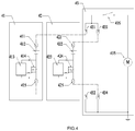
- a power tool 33 is configured to connect with a first battery pack 31 and a second battery pack 32.
- a first positive pole 311 connects with a first positive terminal 331
- a first negative pole 313 connects with a first negative terminal 332
- a second positive pole 321 connects with a second positive terminal 334
- a second negative pole 323 connects with a second negative terminal 335.
- a switch 337 the battery pack 31 and the battery pack 32 are connected in parallel for powering the motor 338.
- the difference between the power tool 33 of FIG. 3 and the power tool 13 as shown in FIG. 1 is that the first switch device 333 is set between a negative node D and the first battery receptacle or the first battery, the second switch device 336 is set between the negative node D and the second battery receptacle or the second battery.
- the first switch device 333 is MOSFET. It includes a first switch terminal for connecting to the negative node D, the second switch terminal for connecting to the first negative terminal 332 and a control terminal for connecting the first controller 339a.
- the second switch device 336 is MOSFET as well. It includes a first switch terminal for connecting the negative node D, the second switch terminal for connecting the second negative terminal 335 and a control terminal for connecting the second controller 339b.
- the first positive terminal 331 and the second positive terminal 334 both connect to the positive node C.
- the control terminal of the first controller connects with the control terminal of the first switch device 333.
- the first controller 339a detects a first voltage drop across the first switch device 333 along the current direction. When the first voltage drop of the first switch device 333 is less than a first predetermined voltage, the first controller 339a sends a signal to cause the first switch device 333 opened to disconnect the first battery pack 31 and the motor 338. Turn on a switch 337, the first battery pack 31 and the motor 338 form a current loop.
- the control terminal of the second controller 339b connects with the control terminal of the second switch device 336.
- the second controller 339b detects a second voltage drop across the second switch device 336 along the current direction.
- the second controller 339b sends a signal to cause the second switch device 336 opened to disconnect the second battery pack 32 and the motor 338. Turn on the switch 337, the second battery pack 32 and the motor 338 form a current loop.
- the first switch device 333 is controlled to be on or closed, the current from the first terminal or the negative node D of the first switch device 333 flows to the second terminal or the first negative terminal 332 of the first switch device 333.Thus, the first voltage drop of the first switch device 333 along the current direction is greater than the first control voltage, controller 339a controls the first switch device 333 closed to form the electrical connection of the first battery or battery pack 31 and the motor 338.
- the second controller 339b detects a second voltage drop between the first terminal and the second terminal of the second switch device 336.
- the second voltage drop as detected along the current direction is less than a second control voltage due to the voltage of the second negative terminal 335 greater than that of the negative node D, the second controller 339b sends a signal to turn off or open the second switch device 336.
- the first battery pack 31 cannot power the second battery pack 32 and the second battery pack 32 cannot output current so as to avoid the current flow of the first battery pack 31 at a high voltage into the second battery pack 32 at a low voltage.
- the voltage drop of the first switch device 331 along the current direction is greater than or equal to the first control voltage which is set for initiating the second switch device 336 and/or the controller 339b, the connection of the first battery pack 31 and the motor 338is enabled to permit the power tool powered by the first battery 31.
- the first controller 339a turns on or closes the first switch device 333 and the second controller 339b turns on or closes the second switch device 336 such that the power tool is powered by both of the battery packs 31, 32 connected in parallel.
- the first controller 339a operable to detect a current voltage of the first battery pack 31, sends a signal to interrupt the connection of the first battery pack and the motor when the current voltage of the first battery pack is less than a first voltage threshold value which is set for preventing the over-discharge of the battery pack 31.
- the second controller 339b operable to detect a current voltage of the second battery pack 32, sends a signal to interrupt the connection of the second battery pack and the motor when the current voltage of the second battery pack is less than a second voltage threshold value which is set for preventing the over-discharge of the second battery pack 32.
- the first controller 339a is operable to detect a current of the first switch device 333, sends a signal to turn off or open the first switch device 333 when the current of the first switch device 333 is less than a first current threshold.
- the second controller 339b is operable to detect a current of the second switch device 336 sends a signal to turn off or open the second switch device 336 when the current of the second switch device 336 is less than a second current threshold.
- a first switch device 414 and a controller 413 can be set within a first battery pack 41.
- a second switch device 424 and a controller 423 can be set within a second battery pack 42.
- the first switch device 414 and the controller 413 are disposed within a housing of the first battery pack 41
- the second switch device 424 and the controller 423 are disposed within a housing of the second battery pack 42.
- the first switch device 414 connects between a first negative terminal 415 and a negative pole of the first battery cell or cells 412.
- the second switch device 424 connects between a second negative terminal 425 and a negative pole of the second battery cell or cells 422.
- the first switch device 414 and the second switch device 424 are MOS FIELD EFFECT TRANSISTORS.
- the controller 413 connects to the control terminal of the first switch device 414 for controlling the connection or disconnection of the first switch device 424.
- the controller 423 connects to the control terminal of the second switch device 424 for controlling the connection or disconnection of the second switch device 424.
- the first negative pole 415 connects with the first negative terminal 432.
- the second positive pole 421 connects with the second positive terminal 433.
- the second negative pole 425 connects with the second negative terminal 434.
- the controllers 413, 423 are operable to detect the voltage of the switch devices 414, 424 and send a signal to open the switch which has a voltage drop less than the first or second control voltage.
- a method of controlling a power tool with a plurality of battery packs connected in parallel comprising: a plurality of battery receptacles each including a positive terminal for connecting the positive electrode of the battery pack and a positive node and a negative terminal for connecting the negative electrode of the battery pack and a negative node, a plurality of switch devices each including a first switch terminal that connects with the negative node and a second switch terminal connectable with the corresponding battery receptacle, a motor connected between the positive node and the negative node; a controller for detecting the voltage drop along the current direction between the first connect terminal and the second connect terminal of each of the switch devices; the method includes: turning on or closing the plurality of switch devices so as to permit the motor be powered by the battery packs; detecting a voltage drop value between the first switch terminal and the second switch terminal of each of the switch devices; judging or determining whether the voltage drop across the respective switch device along the current direction is less than a predetermined value; when the voltage drop of the switch device along the current
- the controller detects a voltage of each of the battery pack; interrupts the connection of the battery pack and the motor when the voltage of a corresponding battery pack is less than a voltage threshold.
- a method of controlling a power tool with two battery packs or batteries connected in parallel comprising:
- the controller detects a current voltage of the first battery pack or battery; interrupts the connection of the first battery pack or battery and the motor when the first battery pack has a voltage less than that of a first voltage threshold which is set for preventing the over-discharge of the first battery pack or battery.
- the controller detects a current voltage of the second battery pack or battery; interrupts the connection of the second battery pack or battery and the motor when the second battery pack has a voltage less than a second voltage threshold which is set for preventing the over-discharge of the second battery pack or battery.
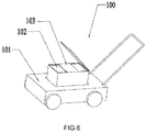
- the mower 100 generally comprises a body 101, a first battery pack 11, a second battery pack 12, etc.
- the body 101 includes battery receptacles 101, 102 for receipt of the battery packs 11, 12 attached to the mower 100.
- the mower 100 includes two battery receptacles 101, 102, each operable to connect a corresponding battery pack 11, 12.
- the battery receptacles 101 and the battery receptacles 102 are placed side by side or set in a line on the body 101 and connected in parallel.
- the power tool includes more than two battery receptacles operable to receive a number of battery packs.
- the battery packs 11, 12 are rechargeable lithium-ion batteries.
- the battery pack 11 and the battery pack 12 have the same battery pack interface or port and the same nominal voltage.
Landscapes
- Engineering & Computer Science (AREA)
- Chemical & Material Sciences (AREA)
- Chemical Kinetics & Catalysis (AREA)
- General Chemical & Material Sciences (AREA)
- Electrochemistry (AREA)
- Power Engineering (AREA)
- Life Sciences & Earth Sciences (AREA)
- Manufacturing & Machinery (AREA)
- Environmental Sciences (AREA)
- Biophysics (AREA)
- Computer Hardware Design (AREA)
- Microelectronics & Electronic Packaging (AREA)
- General Physics & Mathematics (AREA)
- Physics & Mathematics (AREA)
- Charge And Discharge Circuits For Batteries Or The Like (AREA)
- Secondary Cells (AREA)
- Materials Engineering (AREA)
Claims (16)
- Elektrowerkzeug (13, 23, 33, 43, 100), bestehend aus:einem Motor (138, 236, 338, 435);einem ersten Batteriepack (11, 21, 31, 41) mit einer ersten Batterie;einem zweiten Batteriepack (12, 22, 32, 42) mit einer zweiten Batterie, die parallel zur ersten Batterie geschaltet ist;einem ersten Batteriebehälter (101) zur Aufnahme des ersten Batteriepacks;einem zweiten Batteriebehälter (102) für die Aufnahme des zweiten Batteriepacks;einer ersten Schaltvorrichtung (131, 231, 333, 414), die zwischen die erste Batterie und den Motor geschaltet wird, um eine erste elektrische Verbindung zwischen der ersten Batterie und dem Motor herzustellen oder die erste elektrische Verbindung zwischen der ersten Batterie und dem Motor zu unterbrechen;einer zweiten Schaltvorrichtung (134, 223, 336, 424), die zwischen die zweite Batterie und den Motor geschaltet ist, um eine zweite elektrische Verbindung zwischen der zweiten Batterie und dem Motor herzustellen oder die zweite elektrische Verbindung zwischen der zweiten Batterie und dem Motor zu unterbrechen;einem Steuergerät (139, 139a, 139b, 212, 222, 339a, 339b, 413, 423), dadurch gekennzeichnet, dass das Steuergerät so betrieben werden kann:einen ersten Spannungsabfall an der ersten Schaltvorrichtung von einem entsprechenden Punkt mit hohem Potential zu einem entsprechenden Punkt mit niedrigem Potential zu erkennen und die erste Schaltvorrichtung so zu steuern, dass die erste elektrische Verbindung zwischen der ersten Batterie und dem Motor unterbrochen wird, wenn der erste Spannungsabfall kleiner als eine erste Steuerspannung ist;einen zweiten Spannungsabfall an der zweiten Schaltvorrichtung von einem entsprechenden Punkt hohen Potentials zu einem entsprechenden Punkt niedrigen Potentials zu erkennen und die zweite Schaltvorrichtung so zu steuern, dass die elektrische Verbindung zwischen der zweiten Batterie und dem Motor unterbrochen wird, wenn der zweite Spannungsabfall kleiner als eine zweite Steuerspannung ist,eine Spannung des ersten Batteriepacks zu erkennen und die Verbindung zwischen dem ersten Batteriepack und dem Motor zu unterbrechen, wenn die Spannung des ersten Batteriepacks unter einem ersten Spannungsschwellenwert liegt; undeine Spannung des zweiten Batteriepacks zu erkennen und die Verbindung zwischen dem zweiten Batteriepack und dem Motor zu unterbrechen, wenn die Spannung des zweiten Batteriepacks unter einer zweiten Spannungsschwelle liegt.
- Elektrowerkzeug nach Anspruch 1, wobei der erste Steuerspannungswert größer als null ist.
- Elektrowerkzeug nach Anspruch 1, wobei die erste Schaltvorrichtung ein Feldeffekttransistor ist.
- Elektrowerkzeug nach Anspruch 1, wobei die zweite Schaltvorrichtung ein Feldeffekttransistor ist.
- Elektrowerkzeug nach Anspruch 1, wobei die erste Schaltvorrichtung elektrisch mit der zweiten Schaltvorrichtung verbunden ist, sodass der erste Batteriepack und der zweite Batteriepack parallel geschaltet sind, wenn sowohl die erste Schaltvorrichtung als auch die zweite Schaltvorrichtung eingeschaltet sind.
- Elektrowerkzeug nach Anspruch 1, wobei der erste Batteriepack und der zweite Batteriepack Lithiumzellen sind und die gleiche Nennspannung und die gleiche Schnittstelle des Batteriepacks haben.
- Elektrowerkzeug nach Anspruch 1, wobei das Elektrowerkzeug ein Mäher (100) ist, der einen Körper (101) umfasst, und der erste Batteriebehälter und der zweite Batteriebehälter in einer Linie auf dem Körper angeordnet sind.
- Elektrowerkzeug (13, 23, 33, 43, 100), das mit einer Vielzahl von Batteriepacks (11, 21, 31, 41, 12, 22, 32, 42) verbunden werden kann, die jeweils eine positive und eine negative Elektrode aufweisen, wobei das Elektrowerkzeug umfasst:eine Vielzahl von Batteriesteckdosen (101, 102), von denen jede einen positiven Anschluss zum Verbinden der positiven Elektrode des Batteriepacks und eines positiven Knotens und einen negativen Anschluss zum Verbinden der negativen Elektrode des Batteriepacks und eines negativen Knotens umfasst,eine Vielzahl von Schaltvorrichtungen (131, 231, 333, 414, 134, 223, 336, 424), die für die jeweiligen Batteriesteckdosen ausgelegt sind, wobei jede der Schaltvorrichtungen einen ersten Schaltanschluss, der mit dem negativen Knoten verbindbar ist, und einen zweiten Schaltanschluss, der mit dem negativen Anschluss der Batteriesteckdose verbindbar ist, umfasst;einen Motor (138, 236, 338, 435), der zwischen dem positiven Knoten und dem negativen Knoten angeschlossen ist; ein Steuergerät (139, 139a, 139b, 212, 222, 339a, 339b, 413, 423), dadurch gekennzeichnet, dass das Steuergerät so betrieben werden kann, dass es einen Spannungsabfall zwischen dem ersten Schaltanschluss und dem zweiten Schaltanschluss einer jeweiligen Schaltvorrichtung von einem jeweiligen Punkt hohen Potentials zu einem jeweiligen Punkt niedrigen Potentials erfasst und die jeweilige Schaltvorrichtung so steuert, dass die elektrische Verbindung zwischen dem ersten Schaltanschluss und dem zweiten Schaltanschluss unterbrochen wird, wenn der Spannungsabfall der jeweiligen Schaltvorrichtung geringer als eine Steuerspannung ist.
- Elektrowerkzeug nach Anspruch 8, wobei der vorgegebene Wert größer als null ist.
- Elektrowerkzeug nach Anspruch 8, wobei die Schaltvorrichtung ein Feldeffekttransistor ist.
- Elektrowerkzeug nach Anspruch 8, bei dem alle Batteriepacks aus Lithiumzellen bestehen und die gleiche Nennspannung und die gleiche Schnittstelle des Batteriepacks haben.
- Verfahren zum Steuern eines Elektrowerkzeugs (13, 23, 33, 43, 100) mit einer Vielzahl von Batteriepacks (11, 21, 31, 41, 12, 22, 32, 42), die jeweils eine positive Elektrode und eine negative Elektrode aufweisen, wobei das Elektrowerkzeug Folgendes umfasst: eine Vielzahl von Batteriebehältern (101, 102), von denen jeder einen positiven Anschluss zum Verbinden der positiven Elektrode des Batteriesatzes und eines positiven Knotens und einen negativen Anschluss zum Verbinden der negativen Elektrode des Batteriesatzes und eines negativen Knotens aufweist;
eine Vielzahl von Schaltvorrichtungen (131, 231, 333, 414, 134, 223, 336, 424), die jeweils in Reihe mit dem jeweiligen Batteriepack und dem Elektrowerkzeug geschaltet sind, wobei die Schaltvorrichtung einen ersten Schaltanschluss, der mit dem negativen Knoten verbunden ist, und einen zweiten Schaltanschluss, der mit dem negativen Anschluss der Batteriesteckdose verbunden ist, umfasst; einen Motor (138, 236, 338, 435), der zwischen dem negativen Knoten und dem positiven Knoten angeschlossen ist; und einen Controller (139, 139a, 139b, 212, 222, 339a, 339b, 413, 423) zur Steuerung der Schaltvorrichtung und des Motors, wobei das Verfahren dadurch gekennzeichnet ist, dass es umfasst:Schließen der Vielzahl von Schaltvorrichtungen;Erkennen eines Spannungsabfalls zwischen dem ersten Schaltanschluss und dem zweiten Schaltanschluss jeder Schaltvorrichtung von einem jeweiligen Punkt hohen Potentials zu einem jeweiligen Punkt niedrigen Potentials,Beurteilen, ob der Spannungsabfall über dem jeweiligen Schaltgerät kleiner als eine Steuerspannung ist;Steuern der Schaltvorrichtung, um den Batteriepack vom Motor zu trennen, wenn der Spannungsabfall der Schaltvorrichtung geringer als die Steuerspannung ist. - Verfahren nach Anspruch 12, wobei der vorgegebene Wert größer als null ist.
- Verfahren nach Anspruch 12, bei dem die mehreren Schaltvorrichtungen parallel geschaltet werden, wobei die mehreren Batteriepacks in einer parallelen Konfiguration angeordnet werden.
- Verfahren nach Anspruch 12, ferner umfassend,
Ermittlung der aktuellen Spannung eines entsprechenden Batteriepacks durch den Controller,
Unterbrechung der Verbindung zwischen dem Batteriepack und dem Motor, wenn die aktuelle Spannung des Batteriepacks unter einer Spannungsschwelle liegt. - Verfahren nach Anspruch 12, wobei der erste Batteriepack und der zweite Batteriepack Lithiumzellen mit der gleichen Nennspannung und als gleiche Batteriepackschnittstelle sind.
Applications Claiming Priority (2)
| Application Number | Priority Date | Filing Date | Title |
|---|---|---|---|
| CN201510297572 | 2015-06-03 | ||
| PCT/CN2016/084658 WO2016192663A1 (zh) | 2015-06-03 | 2016-06-03 | 电动工具及其控制方法 |
Publications (3)
| Publication Number | Publication Date |
|---|---|
| EP3288147A1 EP3288147A1 (de) | 2018-02-28 |
| EP3288147A4 EP3288147A4 (de) | 2018-04-11 |
| EP3288147B1 true EP3288147B1 (de) | 2020-05-06 |
Family
ID=57440185
Family Applications (1)
| Application Number | Title | Priority Date | Filing Date |
|---|---|---|---|
| EP16802586.4A Active EP3288147B1 (de) | 2015-06-03 | 2016-06-03 | Elektrisches werkzeug und steuerungsverfahren dafür |
Country Status (5)
| Country | Link |
|---|---|
| US (1) | US10277064B2 (de) |
| EP (1) | EP3288147B1 (de) |
| CN (1) | CN106233915B (de) |
| CA (1) | CA2987967C (de) |
| WO (1) | WO2016192663A1 (de) |
Families Citing this family (21)
| Publication number | Priority date | Publication date | Assignee | Title |
|---|---|---|---|---|
| JP5461221B2 (ja) | 2010-02-12 | 2014-04-02 | 株式会社マキタ | 複数のバッテリパックを電源とする電動工具 |
| WO2018138843A1 (ja) * | 2017-01-26 | 2018-08-02 | 株式会社ソニー・インタラクティブエンタテインメント | 電気機器 |
| CN107302248B (zh) * | 2017-07-14 | 2024-01-19 | 宁波锂想电子有限公司 | 一种电动工具 |
| EP3675200B1 (de) * | 2017-08-25 | 2023-07-05 | Positec Power Tools (Suzhou) Co., Ltd | Elektrowerkzeug und verfahren zur stromversorgung eines elektrowerkzeugs |
| CN109995096B (zh) * | 2017-12-29 | 2022-07-12 | 苏州宝时得电动工具有限公司 | 多包并联互充控制电路、控制方法及电动工具 |
| WO2019204561A1 (en) * | 2018-04-18 | 2019-10-24 | Milwaukee Electric Tool Corporation | Tool circuitry for series-type connected battery packs |
| CN110445200B (zh) * | 2018-05-02 | 2023-11-07 | 苏州宝时得电动工具有限公司 | 多包并联的控制电路、控制方法及电动工具 |
| CN110744503B (zh) * | 2018-07-23 | 2022-03-01 | 南京德朔实业有限公司 | 电动工具、电动工具和电池包的组合 |
| CN108879871A (zh) * | 2018-08-03 | 2018-11-23 | 深圳市销邦科技股份有限公司 | 一种安全手柄电池接入电路 |
| JP2020031486A (ja) * | 2018-08-22 | 2020-02-27 | 株式会社マキタ | 電圧供給装置 |
| DE102018216125A1 (de) * | 2018-09-21 | 2020-03-26 | Robert Bosch Gmbh | Verfahren zum Trennen einer Batterie |
| CN110474395A (zh) * | 2019-08-27 | 2019-11-19 | 常州格力博有限公司 | 电力系统 |
| CN112448433B (zh) * | 2019-09-03 | 2024-08-16 | 苏州宝时得电动工具有限公司 | 电动工具 |
| EP3806273A1 (de) | 2019-10-11 | 2021-04-14 | Black & Decker Inc. | Elektrowerkzeug mit aufnahme von batteriepacks mit unterschiedlicher kapazität |
| CN110768361B (zh) * | 2019-11-19 | 2024-02-02 | 格力博(江苏)股份有限公司 | 电动工具 |
| US11691261B2 (en) * | 2020-06-02 | 2023-07-04 | Snap-On Incorporated | Housing clamp for a power tool |
| EP4147299B1 (de) * | 2020-06-18 | 2026-03-11 | Globe (Jiangsu) Co., Ltd. | Elektrowerkzeugsystem |
| CN111584788B (zh) * | 2020-06-18 | 2025-03-21 | 格力博(江苏)股份有限公司 | 电动工具及电动工具系统 |
| CN111584789B (zh) * | 2020-06-18 | 2024-08-20 | 格力博(江苏)股份有限公司 | 电动工具及其系统 |
| US12503004B2 (en) * | 2022-09-13 | 2025-12-23 | GM Global Technology Operations LLC | Contactor operation monitoring for multi-voltage vehicle operation |
| US20240275197A1 (en) * | 2023-02-10 | 2024-08-15 | Greenworks (Jiangsu) Co., Ltd. | Power supply control circuits, power tools, and power tool systems |
Family Cites Families (14)
| Publication number | Priority date | Publication date | Assignee | Title |
|---|---|---|---|---|
| US5684384A (en) * | 1995-10-31 | 1997-11-04 | Motorola, Inc. | Apparatus and method for discharging and charging a multiple battery arrangement |
| JP2006174596A (ja) | 2004-12-15 | 2006-06-29 | Fuji Heavy Ind Ltd | ハイブリッド車のバッテリウォームアップ制御装置 |
| TW200847581A (en) * | 2007-05-28 | 2008-12-01 | Erune Technology Corp | Charging and discharging control method and device for dual-battery and portable electronic device containing the dual-battery charging and discharging control device |
| CN201122861Y (zh) * | 2007-12-04 | 2008-09-24 | 三阳工业股份有限公司 | 具有供电改良结构的电动机车 |
| JP5432761B2 (ja) * | 2010-02-12 | 2014-03-05 | 株式会社マキタ | 複数のバッテリパックを電源とする電動工具 |
| CN102916457B (zh) * | 2011-08-05 | 2015-03-11 | 凹凸电子(武汉)有限公司 | 电池组管理系统及均衡电池组中的电池模块的方法 |
| CN102934316B (zh) * | 2011-06-07 | 2015-01-21 | 丰田自动车株式会社 | 电池系统以及电池系统的控制方法 |
| US8941264B2 (en) * | 2011-06-20 | 2015-01-27 | Bae Systems Information And Electronic Systems Integration Inc. | Apparatus for bi-directional power switching in low voltage vehicle power distribution systems |
| JP5929526B2 (ja) * | 2012-06-01 | 2016-06-08 | ソニー株式会社 | 電源供給装置および電源切り換え方法 |
| CN203027010U (zh) * | 2012-11-30 | 2013-06-26 | 北汽福田汽车股份有限公司 | 一种用于车辆的双蓄电池系统 |
| WO2014153034A1 (en) * | 2013-03-14 | 2014-09-25 | Milwaukee Electric Tool Corporation | Power tool having multiple battery packs |
| CN103516039B (zh) | 2013-09-23 | 2015-11-25 | 深圳市华为技术软件有限公司 | 一种分级供电系统及方法 |
| CN103518487B (zh) * | 2013-09-24 | 2015-09-23 | 浙江亚特电器有限公司 | 一种双电池包驱动割草机 |
| CN103606943B (zh) | 2013-12-02 | 2016-02-24 | 深圳先进储能材料国家工程研究中心有限公司 | 一种微网镍氢电池储能系统 |
-
2016
- 2016-06-02 CN CN201610389158.1A patent/CN106233915B/zh active Active
- 2016-06-03 WO PCT/CN2016/084658 patent/WO2016192663A1/zh not_active Ceased
- 2016-06-03 EP EP16802586.4A patent/EP3288147B1/de active Active
- 2016-06-03 US US15/578,088 patent/US10277064B2/en active Active
- 2016-06-03 CA CA2987967A patent/CA2987967C/en active Active
Non-Patent Citations (1)
| Title |
|---|
| None * |
Also Published As
| Publication number | Publication date |
|---|---|
| US10277064B2 (en) | 2019-04-30 |
| US20180152043A1 (en) | 2018-05-31 |
| WO2016192663A1 (zh) | 2016-12-08 |
| CA2987967A1 (en) | 2016-12-08 |
| CN106233915A (zh) | 2016-12-21 |
| EP3288147A1 (de) | 2018-02-28 |
| CN106233915B (zh) | 2020-05-26 |
| CA2987967C (en) | 2024-02-13 |
| EP3288147A4 (de) | 2018-04-11 |
Similar Documents
| Publication | Publication Date | Title |
|---|---|---|
| EP3288147B1 (de) | Elektrisches werkzeug und steuerungsverfahren dafür | |
| CA2874606C (en) | Adapting a battery voltage | |
| CN101145686B (zh) | 电动工具 | |
| KR101030885B1 (ko) | 이차전지 | |
| EP2528155B1 (de) | Batteriepack | |
| JP7039773B2 (ja) | バッテリーパックを含む電力システム | |
| US8183836B2 (en) | Lithium battery pack | |
| EP2221937A2 (de) | Eingebaute Ladeschaltung für Sekundärbatterie und Sekundärbatterie mit der eingebauten Ladeschaltung | |
| US11031635B2 (en) | Battery pack | |
| EP2317597A1 (de) | Batteriepack | |
| JP2009112192A (ja) | バッテリーパック | |
| JP2004336994A (ja) | バッテリーパック及び該バッテリーパックを内蔵するバッテリーチャージ/ディスチャージ回路 | |
| CN101227096B (zh) | 混合电池及其充电/放电方法 | |
| CN105048006A (zh) | 电池系统及操作电池系统的方法 | |
| KR102609865B1 (ko) | 배터리 팩 및 이를 포함하는 전자 장치 | |
| JP2010104216A (ja) | 電池パックシステム | |
| KR20150107032A (ko) | 배터리 팩 | |
| US20170117723A1 (en) | Battery fleet charging system | |
| JP2001112182A (ja) | 二次電池の保護回路 | |
| AU2017101729A4 (en) | Power tool and control method thereof | |
| JP2004320924A (ja) | 2次電池の過充電保護装置、電源装置及び2次電池の充電制御方法 | |
| EP2221940B1 (de) | Selbstentladende Schaltung für Sekundärbatterie und Sekundärbatterie damit | |
| EP4568056A1 (de) | Batteriepackgruppe und ansteuerungsverfahren dafür | |
| JP2000102176A (ja) | 二次電池パック | |
| JP2011211867A (ja) | 電池パック |
Legal Events
| Date | Code | Title | Description |
|---|---|---|---|
| STAA | Information on the status of an ep patent application or granted ep patent |
Free format text: STATUS: THE INTERNATIONAL PUBLICATION HAS BEEN MADE |
|
| PUAI | Public reference made under article 153(3) epc to a published international application that has entered the european phase |
Free format text: ORIGINAL CODE: 0009012 |
|
| STAA | Information on the status of an ep patent application or granted ep patent |
Free format text: STATUS: REQUEST FOR EXAMINATION WAS MADE |
|
| 17P | Request for examination filed |
Effective date: 20171122 |
|
| AK | Designated contracting states |
Kind code of ref document: A1 Designated state(s): AL AT BE BG CH CY CZ DE DK EE ES FI FR GB GR HR HU IE IS IT LI LT LU LV MC MK MT NL NO PL PT RO RS SE SI SK SM TR |
|
| AX | Request for extension of the european patent |
Extension state: BA ME |
|
| A4 | Supplementary search report drawn up and despatched |
Effective date: 20180314 |
|
| RIC1 | Information provided on ipc code assigned before grant |
Ipc: H02J 7/00 20060101AFI20180308BHEP Ipc: G01R 31/36 20060101ALI20180308BHEP Ipc: B25F 5/00 20060101ALN20180308BHEP |
|
| DAV | Request for validation of the european patent (deleted) | ||
| DAX | Request for extension of the european patent (deleted) | ||
| GRAP | Despatch of communication of intention to grant a patent |
Free format text: ORIGINAL CODE: EPIDOSNIGR1 |
|
| STAA | Information on the status of an ep patent application or granted ep patent |
Free format text: STATUS: GRANT OF PATENT IS INTENDED |
|
| GRAS | Grant fee paid |
Free format text: ORIGINAL CODE: EPIDOSNIGR3 |
|
| RIC1 | Information provided on ipc code assigned before grant |
Ipc: H01M 2/34 20060101ALI20200224BHEP Ipc: G01R 31/36 20200101ALI20200224BHEP Ipc: H01M 10/0525 20100101ALI20200224BHEP Ipc: G01R 19/165 20060101ALI20200224BHEP Ipc: H01M 2/10 20060101ALI20200224BHEP Ipc: B25F 5/00 20060101ALN20200224BHEP Ipc: H02P 7/28 20160101ALI20200224BHEP Ipc: H01M 10/42 20060101ALI20200224BHEP Ipc: H02J 7/00 20060101AFI20200224BHEP |
|
| GRAA | (expected) grant |
Free format text: ORIGINAL CODE: 0009210 |
|
| STAA | Information on the status of an ep patent application or granted ep patent |
Free format text: STATUS: THE PATENT HAS BEEN GRANTED |
|
| INTG | Intention to grant announced |
Effective date: 20200313 |
|
| RIC1 | Information provided on ipc code assigned before grant |
Ipc: G01R 31/36 20200101ALI20200303BHEP Ipc: H01M 2/34 20060101ALI20200303BHEP Ipc: H01M 10/0525 20100101ALI20200303BHEP Ipc: G01R 19/165 20060101ALI20200303BHEP Ipc: H01M 2/10 20060101ALI20200303BHEP Ipc: H01M 10/42 20060101ALI20200303BHEP Ipc: B25F 5/00 20060101ALN20200303BHEP Ipc: H02J 7/00 20060101AFI20200303BHEP Ipc: H02P 7/28 20160101ALI20200303BHEP |
|
| AK | Designated contracting states |
Kind code of ref document: B1 Designated state(s): AL AT BE BG CH CY CZ DE DK EE ES FI FR GB GR HR HU IE IS IT LI LT LU LV MC MK MT NL NO PL PT RO RS SE SI SK SM TR |
|
| REG | Reference to a national code |
Ref country code: GB Ref legal event code: FG4D |
|
| REG | Reference to a national code |
Ref country code: CH Ref legal event code: EP Ref country code: AT Ref legal event code: REF Ref document number: 1268386 Country of ref document: AT Kind code of ref document: T Effective date: 20200515 |
|
| REG | Reference to a national code |
Ref country code: DE Ref legal event code: R096 Ref document number: 602016036006 Country of ref document: DE |
|
| REG | Reference to a national code |
Ref country code: IE Ref legal event code: FG4D |
|
| REG | Reference to a national code |
Ref country code: LT Ref legal event code: MG4D |
|
| REG | Reference to a national code |
Ref country code: NL Ref legal event code: MP Effective date: 20200506 |
|
| PG25 | Lapsed in a contracting state [announced via postgrant information from national office to epo] |
Ref country code: GR Free format text: LAPSE BECAUSE OF FAILURE TO SUBMIT A TRANSLATION OF THE DESCRIPTION OR TO PAY THE FEE WITHIN THE PRESCRIBED TIME-LIMIT Effective date: 20200807 Ref country code: NO Free format text: LAPSE BECAUSE OF FAILURE TO SUBMIT A TRANSLATION OF THE DESCRIPTION OR TO PAY THE FEE WITHIN THE PRESCRIBED TIME-LIMIT Effective date: 20200806 Ref country code: FI Free format text: LAPSE BECAUSE OF FAILURE TO SUBMIT A TRANSLATION OF THE DESCRIPTION OR TO PAY THE FEE WITHIN THE PRESCRIBED TIME-LIMIT Effective date: 20200506 Ref country code: LT Free format text: LAPSE BECAUSE OF FAILURE TO SUBMIT A TRANSLATION OF THE DESCRIPTION OR TO PAY THE FEE WITHIN THE PRESCRIBED TIME-LIMIT Effective date: 20200506 Ref country code: PT Free format text: LAPSE BECAUSE OF FAILURE TO SUBMIT A TRANSLATION OF THE DESCRIPTION OR TO PAY THE FEE WITHIN THE PRESCRIBED TIME-LIMIT Effective date: 20200907 Ref country code: SE Free format text: LAPSE BECAUSE OF FAILURE TO SUBMIT A TRANSLATION OF THE DESCRIPTION OR TO PAY THE FEE WITHIN THE PRESCRIBED TIME-LIMIT Effective date: 20200506 Ref country code: IS Free format text: LAPSE BECAUSE OF FAILURE TO SUBMIT A TRANSLATION OF THE DESCRIPTION OR TO PAY THE FEE WITHIN THE PRESCRIBED TIME-LIMIT Effective date: 20200906 |
|
| PG25 | Lapsed in a contracting state [announced via postgrant information from national office to epo] |
Ref country code: HR Free format text: LAPSE BECAUSE OF FAILURE TO SUBMIT A TRANSLATION OF THE DESCRIPTION OR TO PAY THE FEE WITHIN THE PRESCRIBED TIME-LIMIT Effective date: 20200506 Ref country code: RS Free format text: LAPSE BECAUSE OF FAILURE TO SUBMIT A TRANSLATION OF THE DESCRIPTION OR TO PAY THE FEE WITHIN THE PRESCRIBED TIME-LIMIT Effective date: 20200506 Ref country code: BG Free format text: LAPSE BECAUSE OF FAILURE TO SUBMIT A TRANSLATION OF THE DESCRIPTION OR TO PAY THE FEE WITHIN THE PRESCRIBED TIME-LIMIT Effective date: 20200806 Ref country code: LV Free format text: LAPSE BECAUSE OF FAILURE TO SUBMIT A TRANSLATION OF THE DESCRIPTION OR TO PAY THE FEE WITHIN THE PRESCRIBED TIME-LIMIT Effective date: 20200506 |
|
| REG | Reference to a national code |
Ref country code: AT Ref legal event code: MK05 Ref document number: 1268386 Country of ref document: AT Kind code of ref document: T Effective date: 20200506 |
|
| PG25 | Lapsed in a contracting state [announced via postgrant information from national office to epo] |
Ref country code: AL Free format text: LAPSE BECAUSE OF FAILURE TO SUBMIT A TRANSLATION OF THE DESCRIPTION OR TO PAY THE FEE WITHIN THE PRESCRIBED TIME-LIMIT Effective date: 20200506 Ref country code: NL Free format text: LAPSE BECAUSE OF FAILURE TO SUBMIT A TRANSLATION OF THE DESCRIPTION OR TO PAY THE FEE WITHIN THE PRESCRIBED TIME-LIMIT Effective date: 20200506 |
|
| PG25 | Lapsed in a contracting state [announced via postgrant information from national office to epo] |
Ref country code: EE Free format text: LAPSE BECAUSE OF FAILURE TO SUBMIT A TRANSLATION OF THE DESCRIPTION OR TO PAY THE FEE WITHIN THE PRESCRIBED TIME-LIMIT Effective date: 20200506 Ref country code: IT Free format text: LAPSE BECAUSE OF FAILURE TO SUBMIT A TRANSLATION OF THE DESCRIPTION OR TO PAY THE FEE WITHIN THE PRESCRIBED TIME-LIMIT Effective date: 20200506 Ref country code: SM Free format text: LAPSE BECAUSE OF FAILURE TO SUBMIT A TRANSLATION OF THE DESCRIPTION OR TO PAY THE FEE WITHIN THE PRESCRIBED TIME-LIMIT Effective date: 20200506 Ref country code: CZ Free format text: LAPSE BECAUSE OF FAILURE TO SUBMIT A TRANSLATION OF THE DESCRIPTION OR TO PAY THE FEE WITHIN THE PRESCRIBED TIME-LIMIT Effective date: 20200506 Ref country code: AT Free format text: LAPSE BECAUSE OF FAILURE TO SUBMIT A TRANSLATION OF THE DESCRIPTION OR TO PAY THE FEE WITHIN THE PRESCRIBED TIME-LIMIT Effective date: 20200506 Ref country code: RO Free format text: LAPSE BECAUSE OF FAILURE TO SUBMIT A TRANSLATION OF THE DESCRIPTION OR TO PAY THE FEE WITHIN THE PRESCRIBED TIME-LIMIT Effective date: 20200506 Ref country code: ES Free format text: LAPSE BECAUSE OF FAILURE TO SUBMIT A TRANSLATION OF THE DESCRIPTION OR TO PAY THE FEE WITHIN THE PRESCRIBED TIME-LIMIT Effective date: 20200506 Ref country code: DK Free format text: LAPSE BECAUSE OF FAILURE TO SUBMIT A TRANSLATION OF THE DESCRIPTION OR TO PAY THE FEE WITHIN THE PRESCRIBED TIME-LIMIT Effective date: 20200506 |
|
| REG | Reference to a national code |
Ref country code: CH Ref legal event code: PL |
|
| REG | Reference to a national code |
Ref country code: DE Ref legal event code: R097 Ref document number: 602016036006 Country of ref document: DE |
|
| PG25 | Lapsed in a contracting state [announced via postgrant information from national office to epo] |
Ref country code: PL Free format text: LAPSE BECAUSE OF FAILURE TO SUBMIT A TRANSLATION OF THE DESCRIPTION OR TO PAY THE FEE WITHIN THE PRESCRIBED TIME-LIMIT Effective date: 20200506 Ref country code: SK Free format text: LAPSE BECAUSE OF FAILURE TO SUBMIT A TRANSLATION OF THE DESCRIPTION OR TO PAY THE FEE WITHIN THE PRESCRIBED TIME-LIMIT Effective date: 20200506 Ref country code: MC Free format text: LAPSE BECAUSE OF FAILURE TO SUBMIT A TRANSLATION OF THE DESCRIPTION OR TO PAY THE FEE WITHIN THE PRESCRIBED TIME-LIMIT Effective date: 20200506 |
|
| PLBE | No opposition filed within time limit |
Free format text: ORIGINAL CODE: 0009261 |
|
| STAA | Information on the status of an ep patent application or granted ep patent |
Free format text: STATUS: NO OPPOSITION FILED WITHIN TIME LIMIT |
|
| PG25 | Lapsed in a contracting state [announced via postgrant information from national office to epo] |
Ref country code: LU Free format text: LAPSE BECAUSE OF NON-PAYMENT OF DUE FEES Effective date: 20200603 |
|
| 26N | No opposition filed |
Effective date: 20210209 |
|
| REG | Reference to a national code |
Ref country code: BE Ref legal event code: MM Effective date: 20200630 |
|
| PG25 | Lapsed in a contracting state [announced via postgrant information from national office to epo] |
Ref country code: IE Free format text: LAPSE BECAUSE OF NON-PAYMENT OF DUE FEES Effective date: 20200603 Ref country code: CH Free format text: LAPSE BECAUSE OF NON-PAYMENT OF DUE FEES Effective date: 20200630 Ref country code: LI Free format text: LAPSE BECAUSE OF NON-PAYMENT OF DUE FEES Effective date: 20200630 |
|
| PG25 | Lapsed in a contracting state [announced via postgrant information from national office to epo] |
Ref country code: SI Free format text: LAPSE BECAUSE OF FAILURE TO SUBMIT A TRANSLATION OF THE DESCRIPTION OR TO PAY THE FEE WITHIN THE PRESCRIBED TIME-LIMIT Effective date: 20200506 Ref country code: BE Free format text: LAPSE BECAUSE OF NON-PAYMENT OF DUE FEES Effective date: 20200630 |
|
| PG25 | Lapsed in a contracting state [announced via postgrant information from national office to epo] |
Ref country code: TR Free format text: LAPSE BECAUSE OF FAILURE TO SUBMIT A TRANSLATION OF THE DESCRIPTION OR TO PAY THE FEE WITHIN THE PRESCRIBED TIME-LIMIT Effective date: 20200506 Ref country code: MT Free format text: LAPSE BECAUSE OF FAILURE TO SUBMIT A TRANSLATION OF THE DESCRIPTION OR TO PAY THE FEE WITHIN THE PRESCRIBED TIME-LIMIT Effective date: 20200506 Ref country code: CY Free format text: LAPSE BECAUSE OF FAILURE TO SUBMIT A TRANSLATION OF THE DESCRIPTION OR TO PAY THE FEE WITHIN THE PRESCRIBED TIME-LIMIT Effective date: 20200506 |
|
| PG25 | Lapsed in a contracting state [announced via postgrant information from national office to epo] |
Ref country code: MK Free format text: LAPSE BECAUSE OF FAILURE TO SUBMIT A TRANSLATION OF THE DESCRIPTION OR TO PAY THE FEE WITHIN THE PRESCRIBED TIME-LIMIT Effective date: 20200506 |
|
| REG | Reference to a national code |
Ref country code: DE Ref legal event code: R082 Ref document number: 602016036006 Country of ref document: DE Representative=s name: SUN, YIMING, M.SC. DIPL. SC. POL. UNIV., DE |
|
| PGFP | Annual fee paid to national office [announced via postgrant information from national office to epo] |
Ref country code: DE Payment date: 20250429 Year of fee payment: 10 |
|
| PGFP | Annual fee paid to national office [announced via postgrant information from national office to epo] |
Ref country code: GB Payment date: 20250425 Year of fee payment: 10 |
|
| PGFP | Annual fee paid to national office [announced via postgrant information from national office to epo] |
Ref country code: FR Payment date: 20250508 Year of fee payment: 10 |