EP4177586B1 - Heliumdetektionsvorrichtung und heliumdetektionsgerät - Google Patents
Heliumdetektionsvorrichtung und heliumdetektionsgerät Download PDFInfo
- Publication number
- EP4177586B1 EP4177586B1 EP21950847.0A EP21950847A EP4177586B1 EP 4177586 B1 EP4177586 B1 EP 4177586B1 EP 21950847 A EP21950847 A EP 21950847A EP 4177586 B1 EP4177586 B1 EP 4177586B1
- Authority
- EP
- European Patent Office
- Prior art keywords
- helium
- sealing nozzle
- discharging
- station
- detection device
- Prior art date
- Legal status (The legal status is an assumption and is not a legal conclusion. Google has not performed a legal analysis and makes no representation as to the accuracy of the status listed.)
- Active
Links
Images


Classifications
-
- G—PHYSICS
- G01—MEASURING; TESTING
- G01M—TESTING STATIC OR DYNAMIC BALANCE OF MACHINES OR STRUCTURES; TESTING OF STRUCTURES OR APPARATUS, NOT OTHERWISE PROVIDED FOR
- G01M3/00—Investigating fluid-tightness of structures
- G01M3/02—Investigating fluid-tightness of structures by using fluid or vacuum
- G01M3/04—Investigating fluid-tightness of structures by using fluid or vacuum by detecting the presence of fluid at the leakage point
- G01M3/20—Investigating fluid-tightness of structures by using fluid or vacuum by detecting the presence of fluid at the leakage point using special tracer materials, e.g. dye, fluorescent material, radioactive material
- G01M3/22—Investigating fluid-tightness of structures by using fluid or vacuum by detecting the presence of fluid at the leakage point using special tracer materials, e.g. dye, fluorescent material, radioactive material for pipes, cables or tubes; for pipe joints or seals; for valves; for welds; for containers, e.g. radiators
- G01M3/226—Investigating fluid-tightness of structures by using fluid or vacuum by detecting the presence of fluid at the leakage point using special tracer materials, e.g. dye, fluorescent material, radioactive material for pipes, cables or tubes; for pipe joints or seals; for valves; for welds; for containers, e.g. radiators for containers, e.g. radiators
- G01M3/229—Investigating fluid-tightness of structures by using fluid or vacuum by detecting the presence of fluid at the leakage point using special tracer materials, e.g. dye, fluorescent material, radioactive material for pipes, cables or tubes; for pipe joints or seals; for valves; for welds; for containers, e.g. radiators for containers, e.g. radiators removably mounted in a test cell
-
- G—PHYSICS
- G01—MEASURING; TESTING
- G01M—TESTING STATIC OR DYNAMIC BALANCE OF MACHINES OR STRUCTURES; TESTING OF STRUCTURES OR APPARATUS, NOT OTHERWISE PROVIDED FOR
- G01M3/00—Investigating fluid-tightness of structures
- G01M3/02—Investigating fluid-tightness of structures by using fluid or vacuum
- G01M3/04—Investigating fluid-tightness of structures by using fluid or vacuum by detecting the presence of fluid at the leakage point
-
- H—ELECTRICITY
- H01—ELECTRIC ELEMENTS
- H01M—PROCESSES OR MEANS, e.g. BATTERIES, FOR THE DIRECT CONVERSION OF CHEMICAL ENERGY INTO ELECTRICAL ENERGY
- H01M10/00—Secondary cells; Manufacture thereof
- H01M10/42—Methods or arrangements for servicing or maintenance of secondary cells or secondary half-cells
- H01M10/4228—Leak testing of cells or batteries
-
- Y—GENERAL TAGGING OF NEW TECHNOLOGICAL DEVELOPMENTS; GENERAL TAGGING OF CROSS-SECTIONAL TECHNOLOGIES SPANNING OVER SEVERAL SECTIONS OF THE IPC; TECHNICAL SUBJECTS COVERED BY FORMER USPC CROSS-REFERENCE ART COLLECTIONS [XRACs] AND DIGESTS
- Y02—TECHNOLOGIES OR APPLICATIONS FOR MITIGATION OR ADAPTATION AGAINST CLIMATE CHANGE
- Y02E—REDUCTION OF GREENHOUSE GAS [GHG] EMISSIONS, RELATED TO ENERGY GENERATION, TRANSMISSION OR DISTRIBUTION
- Y02E30/00—Energy generation of nuclear origin
- Y02E30/30—Nuclear fission reactors
Definitions
- the present application relates to the field of airtightness inspection, in particular to a helium detection device and helium detection equipment.
- Airtightness inspection is often required in production and processing of various products such as a square battery.
- a common means for airtightness inspection is helium detection.
- Helium detection involves operations such as filling/recycling of helium into/from products to be inspected in a vacuum chamber.
- An end of a helium injection tube is usually inserted with a sealing nozzle, which enables a good sealing between the tube and a helium injection port of the products to be inspected so as to ensure airtightness during helium injection.
- a sealing nozzle is typically formed from a flexible material such as silicone and rubber, which is prone to material fatigue failure after repeated use and must be replaced. At present, a common choice is manual replacement of a sealing nozzle, which however is inefficient and therefore brings negative influence to normal production schedule.
- the present application provides a technical solution of providing a helium detection device, including:
- the finger-clamp mechanism has a first station and a second station spaced apart, and the clamping assembly is provided at each of the first station and the second station, the clamping assembly located at the second station being configured for capturing the sealing nozzle output by the discharging assembly and transferring the sealing nozzle to the helium injection tube, the clamping assembly located at the first station being configured for capturing the sealing nozzle plugged into the helium injection tube and transferring the sealing nozzle to the recycling assembly.
- the clamping assembly can drive the clamped sealing nozzle to move along an axial direction of the helium injection tube, so as to plug the sealing nozzle into the helium injection tube or to pull out the sealing nozzle from one end of the helium injection tube.
- the clamping assembly includes a strut capable of bearing the sealing nozzle, and a clamping-jaw that is circumferentially provided around the strut and can be opened or closed.
- the finger-clamp mechanism further includes an elevating assembly capable of driving the clamping assembly up and down along an axial direction of the strut, thereby the sealing nozzle stretching into or withdrawing from the clamping-jaw.
- the discharging assembly includes:
- the on-off member includes a jack-up block and a discharging cylinder, the jack-up block being provided on a driving end of the discharging cylinder and configured to be slidable through a side wall of the discharging tube, the discharging cylinder being capable of driving the jack-up block to insert into or withdraw from the discharging tube such that the on-off member can be switched between the blocking state and the open state.
- a feeding port is provided on a side wall of the discharging tube away from the discharging port, a plug pin is provided on an inner wall of the feeding port, and when the sealing nozzle passes through the feeding port in a preset orientation, the groove on the sealing nozzle constitutes an avoidance of the plug pin.
- the recycling assembly includes an attracting member capable of attracting and releasing the sealing nozzle.
- a driving mechanism and a lower cavity mechanism the driving mechanism being capable of driving the finger-clamp mechanism to the helium injection station, the discharging station and the recycling station, the lower cavity mechanism being linked with the finger-clamp mechanism and capable of moving to the helium injection station under the driving of the driving mechanism.
- the helium injection mechanism further includes an isolation valve, the helium injection tube is provided with an injection port at one end of the helium injection tube, and the isolation valve is fixed on one end of the helium injection tube away from the injection port and is in communication with the helium injection tube; and
- the helium injection mechanism includes a fixed base, and the helium injection tube is installed on the fixed base and can stretch out and draw back along a longitudinal direction of the injection port relative to the fixed base.
- the helium injection mechanism further includes a mounting plate and an elastic part, the mounting plate is installed on the fixed base in such a way as to be slidable along the longitudinal direction of the injection port, the helium injection tube is fixedly provided on the mounting plate, and the elastic part provides an elastic force on the mounting plate along the longitudinal direction of the injection port and away from the fixed base.
- the elastic part is a compression spring having an adjustable preload.
- the helium injection tube is in a metal tubular structure.
- the helium injection mechanism further includes a pressure gauge and a three-way tee, and the helium injection tube, the isolation valve and the pressure gauge are in respective communication with three ports of the three-way tee.
- the four-position two-way valve is a solenoid valve.
- helium injection mechanisms there are provided a plurality of the helium injection mechanisms, two adjacent helium injection mechanisms are in communication via the isolation valve, and the air inlet is connected to the isolation valve of one of the helium injection mechanisms.
- a gas-receiving block with a first gas joint, a second gas joint and a third gas joint, the third gas joint being connected to the isolation valve of the one of the helium injection mechanisms, and the first gas joint and the second gas joint are respectively connected to the air inlet and the isolation valve of an adjacent helium injection mechanism.
- a technical solution adopted in the present application is to provide a helium detection equipment, including the helium detection device according to any one of the above preferred embodiments.
- the finger-clamp mechanism can first enable the clamping assembly to enter the helium injection station, and by exchanging the sealing nozzle with the helium injection tube, the clamping assembly can remove the old sealing nozzle plugged into the helium injection tube, and can also reinstall the new sealing nozzle on the helium injection tube; at the recycling station, the clamping assembly can release the old sealing nozzle and hand it over to the recycling assembly; while at the discharging station, the clamping assembly can capture and clamp the new sealing nozzle output by the discharging assembly. It can be seen that the removal of the old sealing nozzle and the installation of the new sealing nozzle are not dependent on manual labor. Therefore, the aforementioned helium detection device can realize the automatic replacement of the sealing nozzle, thereby significantly improving the efficiency of replacing the sealing nozzle.
- the above helium detection device and helium detection equipment realize helium filling operation, helium returning operation, vacuum pumping operation and vacuum breaking operation, and thus the pipeline can be significantly reduced.
- the isolation valve is directly connected with the helium injection tube, which can further reduce pipelines. The reduction of pipeline structure can make the structure of helium injection mechanism simple and easy to maintain. More importantly, fewer pipeline structures can also significantly reduce the adsorption of helium, thereby improving the accuracy of detecting helium.
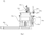
- the helium detection device 10a in the preferred embodiment of the present application includes a helium injection mechanism 100a, a replacing mechanism 200a and a finger-clamp mechanism 300a.
- the helium injection mechanism 100a includes a helium injection tube 110a located at a helium injection station.
- the helium injection tube 110a is typically a metal tubular structure, and is configured for injecting helium into a workpiece to be inspected, such as a square battery.
- the helium detection device 10a further includes a lower cavity mechanism 500a.
- the lower cavity mechanism 500a includes a vacuum box 510a and a jack-up cylinder 520a, and the square battery is placed in the vacuum box 510a.
- the lower cavity mechanism 500a is placed at the helium injection station and below helium injection tube 110a.
- the jack-up cylinder 520a drives the vacuum box 510a and the square battery in the box to rise until the helium injection tube 110a is connected to a helium injection port on the square battery.
- one end of the helium injection tube 110a can be fitted with a sealing nozzle 20a as shown in Fig. 6 .
- the sealing nozzle 20a is in a cylindrical structure with open ends and is generally made of a flexible material such as silicone or rubber.
- the replacing mechanism 200a includes a discharging assembly 210a and a recycling assembly 220a.
- the discharging assembly 210a is provided at a feeding station, and is configured for outputting the sealing nozzle 20a;
- the recycling assembly 220a is provided at a recycling station, and is configured for picking up the sealing nozzle 20a.
- the sealing nozzle 20a output by the discharging assembly 210a is a new sealing nozzle, while the sealing nozzle 20a picked up by the recycling assembly 220a is the old sealing nozzle.
- the discharging assembly 210a includes a discharging tube 211a and an on-off member 212a, wherein:
- the discharging tube 211a is generally a strip-shaped tubular structure, and can be made of metal, plastic, or other materials.
- the discharging tube 211a is configured for storing the sealing nozzle 20a, and at one end of the discharging tube 211a, there is provided a discharging port (not marked in the figures) which is the output end of the discharging assembly 210a.
- a plurality of sealing nozzles 20a are stacked on the discharging tube 211a, and can slide down to the discharging port under the influence of gravity.
- the discharging tube 211a is typically a cylindrical tube with a smooth inner wall, and the plurality of sealing nozzles 20a are stacked along the extending direction of the discharging tube 211a.
- the discharging tube 211a extends vertically, and the sealing nozzle 20a stored therein can slide down to the discharging port under the influence of gravity, thereby realizing the output.
- the on-off member 212a controls whether the sealing nozzle 20a is output from the discharging tube 211a.
- the on-off member 212a has a blocking state and an open state, and can be switched between the blocking state and the open state. In the blocking state, the on-off member 212a can prevent the sealing nozzle 20a from sliding out of the discharging port, while in the open state, the on-off member 212a allows the sealing nozzle 20a to slide out of the discharging port. Therefore, when it is necessary to output the sealing nozzle 20a, the on-off member 212a may be switched to the open state.
- the sealing nozzle 20a can slide down to the discharging port under the influence of gravity without the assistance of other driving elements, thereby contributing to simplifying the structure of the discharging assembly 210a and realizing the process of discharging from the sealing nozzle 20a.
- the discharging assembly 210a may also realize the output of the sealing nozzle 20a in a piston push type, screw feed type, etc.
- the on-off member 212a includes a jack-up block 2121a and a discharging cylinder 2122a.
- the jack-up block 2121a is provided on the driving end of the discharging cylinder 2122a and is configured to slidably pass through the side wall of the discharging tube 211a.
- the discharging cylinder 2122a can drive the jack-up block 2121a into or out of the discharging tube 211a to switch the on-off member 212a between the blocking state and the open state.
- the side wall of the discharging tube 211a may be provided with a through hole for installing the jack-up block 2121a.
- the discharging cylinder 2122a may be fixed relative to the discharging tube 211a with a cylinder mounting plate (not marked in the figures).
- the discharging cylinder 2122a When the discharging cylinder 2122a stretches out, it can drive the jack-up block 2121a to abut against the sealing nozzle 20a in the discharging tube 211a, so as to prevent the nozzle from sliding down from the discharging port, and at this moment, the on-off member 212a is in the blocking state; when the discharging cylinder 2122a retracts, it can drive the jack-up block 2121a to retract, and at this moment, the sealing nozzle 20a can slide down from the discharging port and the on-off member 212a is in the open state.
- a sensor (not shown in the figures) may be provided in the vicinity of the discharging port to detect actions of the sealing nozzle 20a in the discharging tube 211a.
- the sensor detects the actions of the sealing nozzle 20a in the discharging tube 211a.
- the discharging cylinder 2122a can stretch out again and the on-off member 212a switches to the blocking state.
- the on-off member 212a may also be other structures such as baffles, solenoid valves, etc.
- the front and the reverse sides of the sealing nozzle 20a must be discriminated and recognized, as the two ends of the sealing nozzle 20a are structured differently.
- all sealing nozzles 20a need to be stacked in a preset orientation when depositing them in the discharging tube 211a.
- the side wall on the end of the discharging tube 211a away from the discharging port is provided with a feeding port 2111a whose inner wall is provided with a plug pin 2112a, and a groove 21a on the sealing nozzle 20a constitutes an avoidance of the plug pin 2112a as the sealing nozzle 20a passes through the feeding port 2111a in a preset orientation.
- the sealing nozzle 20a has the groove 21a, which is offset from the middle of the sealing nozzle 20a.
- the groove 21a just constitutes an avoidance of the plug pin 2112a, so the sealing nozzle 20a can enter the discharging tube 211a without any problems.
- the plug pin 2112a will block the sealing nozzle 20a so that the latter cannot be smoothly put into the discharging tube 211a. In this way, all the sealing nozzles 20a put into the discharging tube 211a can only pass through the feeding port 2111a in a preset orientation, thereby realizing fool-proofing.
- a recycling assembly 220a includes an attracting member capable of attracting and releasing the sealing nozzle 20a.
- the attracting member may be a vacuum tip, and the recycling assembly 220a can attract and release the sealing nozzle 20a by vacuuming the attracting member and breaking the vacuum thereof, which is convenient to operate.
- the recycling assembly 220a may also pick up the sealing nozzle 20a by means of clamping, for example.
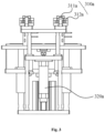
- the finger-clamp mechanism 300a includes a clamping assembly 310a capable of clamping or releasing the sealing nozzle 20a.
- the clamping assembly 310a can be of various types, such as a jaw type, a hoop type, a snap-in type, and the like. Referring together to Fig. 3 , in particular in the present embodiment, the clamping assembly 310a includes a strut 311a and a clamping-jaw 312a, the strut 311a being able to bear the sealing nozzle 20a, the clamping-jaw 312a being provided around the circumference of the strut 311a and being able to be opened or closed.
- the clamping-jaw 312a can be controlled by a jaw cylinder, and by controlling air intake or exhaust, the clamping-jaw 312a can be opened or closed.
- the strut 311a is generally aligned with the extension direction of the helium injection tube 110a.
- the top of the strut 311a is provided with a boss (not marked in the figures) which can be inserted into the sealing nozzle 20a, thus restraining the sealing nozzle 20a.
- the clamping-jaw 312a may be closed to clamp the sealing nozzle 20a, and may be opened to release the sealing nozzle 20a.
- the strut 311a cooperates with the clamping-jaw 312a, which can improve the clamping effect of the sealing nozzle 20a and correct the position of the sealing nozzle 20a on the clamping assembly 310a.
- the inner wall of the clamping-jaw 312a is also provided with a protrusion (not marked in the figures).
- the protrusion may cooperate with the groove 21a, so as to ensure that the sealing nozzle 20a is stable and reliable when clamped by the clamping assembly 310a.
- clamping assembly 310a may be moved to a helium injection station, a discharging station and a recycling station to replace the sealing nozzle 20a plugged into the helium injection tube 110a.
- the clamping assembly 310a can exchange the sealing nozzle 20a with the helium injection tube 110a, the discharging assembly 210a and the recycling assembly 220a, respectively.
- the clamping assembly 310a can pull out the old sealing nozzle 20a on the helium injection tube 110a by driving the sealing nozzle 20a away from the helium injection tube 110a; the clamping assembly 310a can also drive the sealing nozzle 20a to move toward the helium injection tube 110a until the new sealing nozzle 20a clamped thereon is plugged into the helium injection tube 110a, and then release the sealing nozzle 20a and move away from the helium injection tube 110a, so that a new sealing nozzle 20a is installed in the helium injection tube 110a.
- the clamping assembly 310a can be moved to dock with the discharging assembly 210a and clamp the new sealing nozzle 20a output by the discharging assembly 210a. While at the recycling station, the clamping assembly 310a can drive the old sealing nozzle 20a toward the recycling assembly 220a, and then releases the sealing nozzle 20a so that it is picked up by the recycling assembly 220a.
- the clamping assembly 310a can drive the clamped sealing nozzle 20a to move axially along the helium injection tube 110a, so as to plug the sealing nozzle 20a into the helium injection tube 110a or pull out the sealing nozzle 20a from one end of the helium injection tube 110a.
- the sealing nozzle 20a can maintain a straight up and down movement path during installation and removal, thus avoiding breakage of the sealing nozzle 20a due to excessive crushing during installation and removal.
- the finger-clamp mechanism 300a also includes an elevating assembly 320a, which can drive the clamping assembly 310a to move up and down along the axial direction of the strut 311a, so that the sealing nozzle 20a stretches into or withdraw from the clamping-jaw 312a.
- the elevating assembly 320a drives the clamping assembly 310a up until the sealing nozzle 20a stretches into the clamping-jaw 312a and is carried on the strut 311a. Then, the clamping-jaw 312a is closed, and the elevating assembly 320a drives the clamping assembly 310a down.
- the elevating assembly 320a drives the clamping assembly 310a up first until the helium injection tube 110a is plugged into the sealing nozzle 20a. Then, the clamping-jaw 312a is opened, and the elevating assembly 320a drives the clamping assembly 310a down to allow the sealing nozzle 20a to withdraw from the range of the clamping-jaw 312a.
- a structure such as a multi-degree-of-freedom manipulator may also be used instead of the elevating assembly 320a.
- the finger-clamp mechanism 300a can be provided with a corresponding drive structure therein so as to drive the clamping assembly 310a to flow among the helium injection station, the discharging station and the recycling station.
- an additional drive structure may be provided and drive finger-clamp mechanism 300a as a whole to flow among the helium injection station, the discharging station and the recycling station.
- the helium detection device 10a further includes a driving mechanism 400a that drives the finger-clamp mechanism 300a to move to the helium injection station, the discharging station, and the recycling station.
- the driving mechanism 400a may be composed of a power element such as a motor, a cylinder, an electric cylinder, etc., and its matching transmission elements.
- the driving mechanism 400a includes a servo motor (not marked in the figures), an electric cylinder (not marked in the figures) and a moving plate 410a, wherein the servo motor and the electric cylinder together drive the moving plate 410a to move in a preset direction.
- the finger-clamp mechanism 300a is provided on the moving plate 410a and can move with the moving plate 410a. In this way, the structure of the finger-clamp mechanism 300a itself can be simplified.
- the finger-clamp mechanism 300a is also provided with a waste box 330a.
- the waste box 330a is aligned with the recycling assembly 220a when the driving mechanism 400a drives the finger-clamp mechanism 300a to arrive at the feeding station.
- the recycling assembly 220a releases the picked sealing nozzle 20a, so that the old sealing nozzle 20a falls into the waste box 330a.
- the waste box 330a may be omitted, and the recycling assembly 220a may be a vacuum suction pipeline connected to a material box, and the attracted old sealing nozzle 20a is directly sucked into the material box.
- a lower cavity mechanism 500a is linked with the finger-clamp mechanism 300a, and can be moved to the helium injection station under the driving of the driving mechanism 400a.
- the lower cavity mechanism 500a is fixedly provided on the moving plate 410a.
- the finger-clamp mechanism 300a enters the helium injection station under the driving of the driving mechanism 400a
- the lower cavity mechanism 500a automatically exits the helium injection station. That is, under the driving of the driving mechanism 400a, the lower cavity mechanism 500a and the finger-clamp mechanism 300a can only alternate but not enter the helium injection station at the same time, thus avoiding mutual interference between them.
- the lower cavity mechanism 500a further includes a supporting plate 530a and a guide rod 540a.
- One end of the guide rod 540a is fixedly provided on the mounting plate of the driving mechanism 400a, and the supporting plate 530a is provided on the guide rod 540a through a linear bearing, so that the supporting plate 530a may slide along the extending direction of the guide rod 540a.
- the vacuum box 510a is fixedly provided on the supporting plate 530a.
- the jack-up cylinder 520a is connected to the supporting plate 530a by drive and can drive the supporting plate 530a to slide along the guide rod 540a, thereby driving the vacuum box 510a up and down.
- the lower cavity mechanism 500a also includes a stop screw 550a. After the vacuum box 510a has been raised into place, the stop screw 550a is able to hold the vacuum box 510a in place, thus allowing the helium injection process to remain stable.
- the finger-clamp mechanism 300a has a first station 301a and a second station 302a spaced apart from each other, and a clamping assembly 310a is provided on the first station 301a and the second station 302a.
- the clamping assembly 310a located on the second station 302a is configured for capturing the sealing nozzle 20a output by the discharging assembly 210a, and transferring the sealing nozzle 20a to the helium injection tube 110a, while the clamping assembly 310a located on the first station 301a is configured for capturing the sealing nozzle 20a plugged in the helium injection tube 110a, and transferring the sealing nozzle 20a to the recycling assembly 220a.
- the finger-clamp mechanism 300a enters the helium injection station under the driving of the driving mechanism 400a, and aligns the clamping assembly 310a located at the first station 301a with the end of the helium injection tube 110a; then, the elevating assembly 320a jacks up the clamping assembly 310a, the strut 311a of the clamping assembly 310a at the first station 301a bears the sealing nozzle 20a, and the clamping-jaw 312a is closed and clamps the sealing nozzle 20a; finally, the elevating assembly 320a retracts, and drives the clamping assembly 310a to move downward, thereby pulling out the old sealing nozzle 20a.
- the finger-clamp mechanism 300a is under the driving of the driving mechanism 400a to arrive at the recycling station, and aligns the clamping assembly 310a located at the first station 301a with the recycling assembly 220a; the elevating assembly 320a jacks up the clamping assembly 310a again until the old sealing nozzle 20a is sent to the recycling assembly 220a; then, the clamping-jaw 312a is opened, and the elevating assembly 320a retracts to drive the clamping assembly 310a to move downward, thereby transferring the old sealing nozzle 20a to the recycling assembly 220a for recycling.
- the finger-clamp mechanism 300a is under the driving of the driving mechanism 400a to arrive at the feeding station and aligns the clamping assembly 310a located at second station 302a with the output end of discharging assembly 210a; the new sealing nozzle 20a falls from the discharging tube 211a onto the strut 311a located at the second station 302a, and the clamping-jaw 312a is closed to clamp the nozzle 20a, so as to realize the feeding of the new sealing nozzle 20a;
- the finger-clamp mechanism 300a enters the helium injection station under the driving of the driving mechanism 400a, and aligns the clamping assembly 310a located at the second station 302a with the end of the helium injection tube 110a; the elevating assembly 320a jacks up the clamping assembly 310a until the clamped new sealing nozzle 20a is plugged in the helium injection tube 110a; then, the clamping-jaw 312a is
- the finger-clamp mechanism 300a can be brought to the feeding station, and the new sealing nozzle 20a can be transferred to the clamping assembly 310a located at the second station 302a.
- the driving mechanism 400a directly drives the clamping assembly 310a located at the second station 302a to align with the end of the helium injection tube 110a.
- the elevating assembly 320a and the clamping assembly 310a operate to install the new sealing nozzle 20a on the end of the helium injection tube 1 10a. In this way, the travel of the driving mechanism 400a during the replacement of the sealing nozzle 20a can be reduced, helping to further improve efficiency.
- the clamping assembly 310a on the first station 301a can also be used for replacing the new sealing nozzle 20a, and the clamping assembly 310a on the second station 302a can be used for recycling the old sealing nozzle 20a.
- the clamping assembly 310a at the first station 301a is taking on the new sealing nozzle 20a
- the clamping assembly 310a at the second station 302a can transfer the old sealing nozzle 20a to the recycling assembly 220a, thus being able to further improve the efficiency of replacing the sealing nozzle.
- only one clamping assembly 310a may be installed on the finger-clamp mechanism 300a, and the same clamping assembly 310a can perform the extraction of the old sealing nozzle 20a and the installation of the new sealing nozzle 20a.
- the finger-clamp mechanism 300a can first enable the clamping assembly 310a to enter the helium injection station, and by exchanging the sealing nozzle 20a with the helium injection tube 110a, the clamping assembly 310a can remove the old sealing nozzle 20a plugged into the helium injection tube 110a, and can also reinstall the new sealing nozzle 20a on the helium injection tube 110a; at the recycling station, the clamping assembly 310a can release the old sealing nozzle 20a and hand it over to the recycling assembly 220a; while at the discharging station, the clamping assembly 310a can capture and clamp the new sealing nozzle 20a output by the discharging assembly 210a.
- the removal of the old sealing nozzle 20a and the installation of the new sealing nozzle 20a are not dependent on manual labor. Therefore, the aforementioned helium detection device 10a can realize the automatic replacement of the sealing nozzle 20a, thereby significantly improving the efficiency of replacing the sealing nozzle 20a.
- a helium detection device (not shown in the figures) is provided by the present application, and the helium detection device includes a helium injection mechanism 100a.
- the aforementioned helium detection device further includes a helium filling device (not shown in the figures), a helium returning device (not shown in the figures), a vacuum pumping device (not shown in the figures), and a vacuum breaking device (not shown in the figures).
- the vacuum pumping device evacuates the vacuum box used for loading a workpiece to be inspected to form a vacuum environment; the helium filling device supplies helium, and injects the helium into the workpiece to be inspected located in the vacuum box through the helium injection mechanism 100a, such as a square battery; after holding the pressure for a preset time, the helium returning device recycles the helium from the workpiece and inspects the airtightness of the workpiece by calculating the concentration of helium in the vacuum box; after the inspection is completed, the vacuum breaking device restores the air pressure in the vacuum box.
- the vacuum breaking device is a muffler.
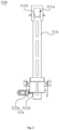
- the helium detection device in the preferred embodiment of the present application includes a helium injection mechanism 100a and a four-position two-way valve 200, wherein:
- the helium injection mechanism 100a includes the helium injection tube 110a and an isolation valve 120.
- the helium injection tube 110a is generally in a bar-shaped tubular structure with both ends open.
- One end of the helium injection tube 110a is provided with an injection port (not marked in the figures) which is capable of docking with the helium injection port of the workpiece to be inspected.
- the isolation valve 120 is fixed on the end of the helium injection tube 110a away from the injection port and is in communication with the helium injection tube 110a.
- the helium gas supplied by the helium injection mechanism enters into the helium injection tube 110a through the isolation valve 120, and is injected into the workpiece to be inspected from the injection port of the helium injection tube 110a. Then, the isolation valve 120 is closed, so that it is possible to hold the pressure of the workpiece to be inspected injected with the helium gas.
- a helium-injecting sealing nozzle 20a is also installed on the injection port, and the helium-injecting sealing nozzle 20a may be a member formed by flexible materials such as rubber and silica gel.
- the helium-injecting sealing nozzle 20a can be elastically deformed by extrusion to fill the gap between the injection port and the helium injection port, thereby achieving a better sealing effect.
- the helium injection tube 110a is a metallic tubular structure.
- the helium injection tube 110a may be formed from metallic materials such as stainless steel.
- the metallic tubular structure has a high mechanical strength, which prevents the helium injection tube 110a from being deformed during the helium injection process.
- the metallic tubular structure can effectively reduce the helium absorption and helium accumulation in the helium injection tube 110a, thereby improving the accuracy of detecting helium.
- the helium injection mechanism 100a further includes a pressure gauge 160 and a three-way tee 170, and the helium injection tube 110a, the isolation valve 120, and the pressure gauge 160 are in respective communication with the three ports of the three-way tee 170.
- the three-way tee 170 is a hollow block structure with three ports, and is generally formed of metal.
- the pressure gauge 160 can detect the air pressure in the workpiece to be inspected, thus facilitating the control of the amount of the helium gas filled into the workpiece to be inspected.
- the helium injection tube 110a, the isolation valve 120 and the pressure gauge 160 are directly connected through the three-way tee 170 without an additional pipeline for communicating them with each other, thereby further reducing the adsorption of the helium gas.
- the four-position two-way valve 200 has an air inlet 210 and four air outlets 220, wherein the air inlet 210 is capable of alternately conducting with the four air outlets 220.
- the four-position two-way valve 200 has four on-off states, and in a particular on-off state, the air inlet 210 is in conduction with a corresponding one air outlet 220 and isolated from the other air outlets 220.
- the four-position two-way valve 200 is connected in reverse, the air inlet 210 is connected to the helium injection tube 110a through the isolation valve 120, and the four air outlets 220 are respectively connected to the helium filling device, the helium returning device, the vacuum pumping device and the vacuum breaking device.
- the helium detection equipment generally has a top plate 30 that acts as a support, and the four-position two-way valve 200 and the helium injection mechanism 100a can be fixed on a surface of the top plate 30.
- the air inlet 210 of the four-position two-way valve 200 can be connected with the isolation valve 120 through a pipeline (not shown in the figures).
- the isolation valve 120 is directly connected with the helium injection tube 110a, which can further reduce the number of pipelines. The reduction of the pipeline structure can reduce the adsorption of helium gas, thereby improving the accuracy of detecting helium.
- the four-position two-way valve 200 is a solenoid valve. Therefore, on-off states of the four-position two-way valve 200 can be switched by inputting different electrical signals, so it is possible to respond quickly and switch easily. Obviously, it is also possible to mechanically control the four-position two-way valve 200 to switch the on-off states.
- the helium injection mechanism 100a includes a fixed base 130 where the helium injection tube 110a is installed, and the helium injection tube 110a is capable of stretching out and drawing back along the longitudinal direction of the injection port with respect to the fixed base 130.
- the fixed base 130 acts as a support and can be fixedly mounted on the top plate 30 of the helium detection equipment.
- the helium injection tube 110a When the helium detection equipment is in operation, the helium injection tube 110a generally extends in a vertical direction, so the longitudinal direction of the injection port is the up and down direction shown in Fig. 7 .
- the vacuum box located at the lower part of the helium injection mechanism 100a is jacked up until the helium injection port of the workpiece to be inspected inside the box is docked with the injection port of the helium injection tube 110a. Since the helium injection mechanism 100a is capable of stretching out and drawing back, the helium injection tube 110a will be forced to retract when the helium injection port and the injection port abut, thereby avoiding damage to the helium injection tube 110a and the workpiece to be inspected due to hard contact between the helium injection tube 110a and the helium injection port.
- the helium injection mechanism 100a also includes a mounting plate 140 and an elastic part 150, the mounting plate 140 is installed on the fixed base 130 in such a way as to be slidable along the longitudinal direction of the injection port, the helium injection tube 110a is fixedly installed on the mounting plate 140, and the elastic part 150 provides an elastic force on the mounting plate 140 along the longitudinal direction of the injection port and away from the fixed base 130.
- the mounting plate 140 is slidably mounted on the fixed base 130 through the cooperation of a guide rail and a slider, and the guide rail extends in the up and down direction as shown in Fig. 7 .
- the helium injection port and the injection port are effectively tightened by the elastic force of the elastic part 150, thereby further improving the sealing effect between the two.
- the helium injection tube 110a can also be made to stretch out and draw back elastically in other ways.
- the helium injection tube 110a is provided with a corrugated section capable of elastic deformation.
- a cylinder is provided, wherein the cylinder is fixed to the fixed base 130 and the helium injection tube 110a is fixed to the driving end of the cylinder, thereby enabling the helium injection tube 110a to stretch out and draw back relative to the fixed base 130.
- the elastic part 150 is a compression spring, and the compression spring has an adjustable preload.
- the compression spring is clamped between the fixed base 130 and the mounting plate 140.
- the helium injection port abuts against the injection port, the helium injection tube 110a is forced to retract, thereby further compressing the compression spring.
- the preload of the compression spring it is possible to adjust the amount of elastic return force provided by the elastic part 150, thereby adjusting the tightness of the helium injection port against the injection port as desired.
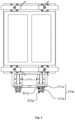
- multiple helium injection mechanisms 100a wherein two adjacent helium injection mechanisms 100a are connected through the isolation valve 120, and the air inlet 210 is connected to the isolation valve 120 of one of the helium injection mechanisms 100a.
- the helium gas supplied by the helium filling device can be distributed to multiple helium injection mechanisms 100a through a four-position two-way valve 200, and the helium gas recycled by the multiple helium injection mechanisms 100a can be collected to the helium returning device through the four-position two-way valve 200.
- the helium gas supplied by the helium filling device can be distributed to multiple helium injection mechanisms 100a through a four-position two-way valve 200, and the helium gas recycled by the multiple helium injection mechanisms 100a can be collected to the helium returning device through the four-position two-way valve 200.
- the helium injection mechanism 100a also includes a gas-receiving block 300 which has a first gas joint 310, a second gas joint 320 and a third gas joint (not shown in the figures), wherein the third gas joint is connected to the isolation valve 120 of one of the helium injection mechanisms 100a, and the first gas joint 310 and the second gas joint 320 are respectively connected to the air inlet 210 and the isolation valve 120 of the adjacent helium injection mechanism 100a.
- the gas-receiving block 300 may be a metal-formed hollow structure. Specifically, the isolation valve 120 itself has several gas joints (not marked in the figures), and the gas-receiving block 300 can be docked with any gas joint on the isolation valve 120, thereby increasing the number of ports of the isolation valve 120 to facilitate the connection of an adjacent helium injection mechanism 100a and the helium injection mechanism 100a to the four-position two-way valve 200.
- the gas-receiving block 300 can be omitted.
- the air inlet 210 of the four-position two-way valve 200 can be directly connected to the gas joint provided by the isolation valve 120 itself.
- the four-position two-way valve 200 By using the four-position two-way valve 200 to connect the helium injection mechanism 100a with the helium filling device, the helium returning device, the vacuum pumping device and the vacuum breaking device and by switching the state of the four-position two-way valve 200, the above helium detection device and helium detection equipment realize helium filling operation, helium returning operation, vacuum pumping operation and vacuum breaking operation, and therefore the number of the pipelines can be significantly reduced.
- the isolation valve 120 is directly connected with the helium injection tube 110a, which can further reduce the number of pipelines.
- the reduction of pipeline structure can make the structure of helium injection mechanism simple and easy to maintain. More importantly, fewer pipeline structures can also significantly reduce the adsorption of helium, thereby improving the accuracy of detecting helium.
Landscapes
- Physics & Mathematics (AREA)
- General Physics & Mathematics (AREA)
- Engineering & Computer Science (AREA)
- Manufacturing & Machinery (AREA)
- Chemical & Material Sciences (AREA)
- Chemical Kinetics & Catalysis (AREA)
- Electrochemistry (AREA)
- General Chemical & Material Sciences (AREA)
- Examining Or Testing Airtightness (AREA)
Claims (20)
- Helium-Detektionsvorrichtung, umfassend:
einen Helium-Injektionsmechanismus (100a), der ein Helium-Injektionsrohr (110a) umfasst, das an einer Helium-Injektionsstation angeordnet ist, wobei eine Dichttülle (20a) in einem Ende des Helium-Injektionsrohrs (110a) einsteckbar ist, dadurch gekennzeichnet, dass das Gerät ferner Folgendes umfasst:einen Austauschmechanismus (200a), der eine Ausgabekomponente (210a), die an einer Zuführstation angeordnet ist, und eine Rücknahmekomponente (220a), die an einer Rücknahmestation angeordnet ist, umfasst, wobei die Ausgabekomponente (210a) zum Ausgeben der Dichttülle (20a) und die Rücknahmekomponente (220a) zum Aufnehmen der Dichttülle (20a), undeinen Fingerklemmmechanismus (300a), der eine Klemmkomponente (310a) umfasst, wobei die Klemmkomponente (310a) in der Lage ist, die Dichttülle (20a) zu klemmen oder lösen, und die Klemmkomponente (310a) in der Lage ist, sich zur Helium-Injektionsstation, zur Ausgabestation und zur Rücknahmestation zu bewegen, um die in dem Helium-Injektionsrohr (110a) eingesteckte Dichttülle (20a) auszutauschen. - Helium-Detektionsvorrichtung nach Anspruch 1, wobei der Fingerklemmmechanismus (300a) eine erste Station (301a) und eine zweite Station (302a) aufweist, die voneinander beabstandet sind, wobei die erste Station (301a) und die zweite Station (302a) jeweils mit der Klemmkomponente (310a) versehen sind, wobei die an der zweiten Station (302a) befindliche Klemmkomponente (310a) dazu dient, die von der Ausgabekomponente (210a) ausgegebene Dichttülle (20a) zu erhalten und die Dichttülle (20a) zum Helium-Injektionsrohr (110a) zu transferieren, und die an der ersten Station (301a) befindliche Klemmkomponente (310a) dazu dient, die in dem Helium-Injektionsrohr (110a) eingesteckte Dichttülle (20a) zu erhalten und die Dichttülle (20a) zur Rücknahmekomponente (220a) zu transferieren.
- Helium-Detektionsvorrichtung nach Anspruch 1, wobei die Klemmkomponente (310a) in der Lage ist, die geklemmte Dichttülle (20a) axial entlang des Helium-Injektionsrohrs (110a) zu bewegen, um die Dichttülle (20a) in dem Helium-Injektionsrohr (110a) einzustecken oder die Dichttülle (20a) aus einem Ende des Helium-Injektionsrohrs (110a) herauszuziehen.
- Helium-Detektionsvorrichtung nach Anspruch 1, wobei die Klemmkomponente (310a) eine Stütze (311a) und eine Greifzange (312a) umfasst, wobei die Stütze (311a) in der Lage ist, die Dichttülle (20a) zu tragen, und die Greifzange (312a) um den Umfang der Stütze (311a) herum angeordnet ist und sich öffnen oder schließen lässt.
- Helium-Detektionsvorrichtung nach Anspruch 4, wobei der Fingerklemmmechanismus (300a) ferner eine Hebekomponente (320a) umfasst, wobei die Hebekomponente (320a) in der Lage ist, die Klemmkomponente (310a) entlang der axialen Richtung der Stütze (311a) anzuheben oder abzusenken, so dass die Dichttülle (20a) in die Greifzange (312a) hineingeführt oder aus dieser herausgeführt wird.
- Helium-Detektionsvorrichtung nach Anspruch 1, wobei die Ausgabekomponente (210a) Folgendes umfasst:ein Ausgaberohr (211a) zum Aufbewahren der Dichttülle (20a), wobei das Ausgaberohr (211a) an einem Ende mit einer Auslassöffnung versehen ist, wobei mehrere Dichttüllen (20a) im Ausgaberohr (211a) gestapelt sind und unter dem Einfluss der Schwerkraft zur Auslassöffnung gleitbar ist;ein Schaltelement (212a), das einen blockierenden Zustand, in dem das Herausgleiten der Dichttülle (20a) aus der Auslassöffnung verhindert wird, und einen offenen Zustand aufweist, in dem das Herausgleiten der Dichttülle (20a) aus der Auslassöffnung erlaubt wird, wobei das Schaltelement (212a) zwischen dem blockierenden Zustand und dem offenen Zustand wechselbar ist.
- Helium-Detektionsvorrichtung nach Anspruch 6, wobei das Schaltelement (212a) einen oberen Block (2121a) und einen Ausgabezylinder (2122a) umfasst, wobei der obere Block (2121a) am Antriebsende des Ausgabezylinders (2122a) angeordnet ist, und gleitend durch die Seitenwand des Ausgaberohrs (211a) geführt ist, und der Ausgabezylinder (2122a) in der Lage ist, den oberen Block (2121a) in das Ausgaberohr (211a) hinein oder aus ihm heraus zu treiben, so dass das Schaltelement (212a) zwischen dem blockierenden Zustand und dem offenen Zustand wechselt.
- Helium-Detektionsvorrichtung nach Anspruch 6, wobei die Seitenwand des von der Auslassöffnung entfernten Endes des Ausgaberohrs (211a) mit einer Einlassöffnung (2111a) versehen ist, wobei die Innenwand der Einlassöffnung (2111a) mit einem Stift (2112a) versehen ist, und eine Nut (21a) an der Dichttülle (20a) einen Freiraum für den Stift (2112a) bildet, wenn die Dichttülle (20a) in einer vorbestimmten Ausrichtung durch die Einlassöffnung (2111a) hindurchgeht.
- Helium-Detektionsvorrichtung nach Anspruch 1, wobei die Rücknahmekomponente (220a) ein Saugelement umfasst, das in der Lage ist, die Dichttülle (20a) anzusaugen und freizugeben.
- Helium-Detektionsvorrichtung nach einem der Ansprüche 1 bis 9, wobei es ferner einen Antriebsmechanismus (400a) und einen unteren Hohlraummechanismus (500a), wobei der Fingerklemmmechanismus (300a) in der Lage ist, sich unter dem Antreiben des Antriebsmechanismus (400a) zur Helium-Injektionsstation, zur Ausgabestation und zur Rücknahmestation zu bewegen, der untere Hohlraummechanismus (500a) mit dem Fingerklemmmechanismus (300a) verbunden ist und in der Lage ist, sich unter dem Antreiben des Antriebsmechanismus (400a) zur Helium-Injektionsstation zu bewegen.
- Helium-Detektionsvorrichtung nach Anspruch 1, wobei der Helium-Injektionsmechanismus (100a) ferner ein Absperrventil (120) umfasst, das Helium-Injektionsrohr (110a) an einem Ende mit einer Injektionsöffnung versehen ist, wobei das Absperrventil (120) am von der Injektionsöffnung entfernten Ende des Helium-Injektionsrohrs (110a) befestigt ist und an das Helium-Injektionsrohr (110a) angeschlossen ist,die Helium-Detektionsvorrichtung ferner ein Vier-Wege-Zwei-Positionen-Ventil (200) mit einem Lufteinlass (210) und vier Luftauslässen (220) umfasst, wobei der Lufteinlass (210) abwechselnd mit den vier Luftauslässen(220) verbindbar ist,wobei der Lufteinlass (210) über das Absperrventil (120) mit dem Helium-Injektionsrohr (110a) verbunden ist und die vier Luftauslässe (220) jeweils zur Verbindung mit einer Helium-Einfüllvorrichtung, einer Helium-Rückführvorrichtung, einer Vakuumpumpe und einer Vakuumaufhebungsvorrichtung dienen.
- Helium-Detektionsvorrichtung nach Anspruch 11, wobei der Helium-Injektionsmechanismus (100a) eine Halterung (130) umfasst, wobei das Helium-Injektionsrohr (110a) auf der Halterung (130) angebracht ist und das Helium-Injektionsrohr (110a) in Richtung der Längsachse der Injektionsöffnung relativ zur Halterung (130) teleskopierbar ist.
- Helium-Detektionsvorrichtung nach Anspruch 12, wobei der Helium-Injektionsmechanismus (100a) ferner eine Montageplatte (140) und ein elastisches Element (150) umfasst, wobei sich die Montageplatte (140) in Richtung der Längsachse der Injektionsöffnung gleitend auf der Halterung (130) montiert ist, das Helium-Injektionsrohr (110a) fest an der Montageplatte (140) angeordnet ist, und das elastische Element (150) in Richtung der Längsachse der Injektionsöffnung eine elastische Kraft auf die Montageplatte (140) ausübt, sodass sich sie von der Halterung (130) weg bewegt.
- Helium-Detektionsvorrichtung nach Anspruch 13, wobei das elastische Element (150) eine Druckfeder ist, wobei der Vorspannungsbetrag der Druckfeder einstellbar ist.
- Helium-Detektionsvorrichtung nach Anspruch 11, wobei das Helium-Injektionsrohr (110a) eine Metallrohrstruktur ist.
- Helium-Detektionsvorrichtung nach Anspruch 11, wobei der Helium-Injektionsmechanismus (100a) ferner ein Manometer (160) und einen T-Stück-Block (170) umfasst, wobei das Helium-Injektionsrohr (110a), das Absperrventil (120) und das Manometer (160) jeweils an die drei Anschlüssen des T-Stück-Blocks (170) angeschlossen sind.
- Helium-Detektionsvorrichtung nach Anspruch 11, wobei das Vier-Wege-Zwei-Positionen-Ventil ein Magnetventil ist.
- Helium-Detektionsvorrichtung nach Anspruch 11, wobei mehrere Helium-Injektionsmechanismen (100a) vorhanden sind und zwei benachbarte Helium-Injektionsmechanismen (100a) über das Absperrventil (120) aneinander angeschlossen sind, und der Lufteinlass (210) mit dem Absperrventil (120) eines der Helium-Injektionsmechanismen (100a) verbunden ist.
- Helium-Detektionsvorrichtung nach Anspruch 18, wobei es ferner einen Gasanschlussblock (300) umfasst, wobei der Gasanschlussblock (300) einen ersten Gasanschluss (310), einen zweiten Gasanschluss (320) und einen dritten Gasanschluss aufweist, wobei der dritte Gasanschluss mit dem Absperrventil (120) eines der Helium-Injektionsmechanismen (100a) verbunden ist, und der erste Gasanschluss (310) und der zweite Gasanschluss (320) mit dem Lufteinlass (210) bzw. dem Absperrventil (120) des benachbarten Helium-Injektionsmechanismus (100a) verbunden sind.
- Helium-Detektionsvorrichtung, wobei die die Helium-Detektionsvorrichtung nach einem der Ansprüche 1 bis 19 umfasst.
Applications Claiming Priority (3)
| Application Number | Priority Date | Filing Date | Title |
|---|---|---|---|
| CN202110824783.5A CN113567062B (zh) | 2021-07-21 | 2021-07-21 | 氦检装置 |
| CN202121670147.3U CN215414242U (zh) | 2021-07-21 | 2021-07-21 | 注氦装置及氦检设备 |
| PCT/CN2021/140324 WO2023000609A1 (zh) | 2021-07-21 | 2021-12-22 | 氦检装置及氦检设备 |
Publications (3)
| Publication Number | Publication Date |
|---|---|
| EP4177586A1 EP4177586A1 (de) | 2023-05-10 |
| EP4177586A4 EP4177586A4 (de) | 2024-03-13 |
| EP4177586B1 true EP4177586B1 (de) | 2024-12-11 |
Family
ID=84980466
Family Applications (1)
| Application Number | Title | Priority Date | Filing Date |
|---|---|---|---|
| EP21950847.0A Active EP4177586B1 (de) | 2021-07-21 | 2021-12-22 | Heliumdetektionsvorrichtung und heliumdetektionsgerät |
Country Status (4)
| Country | Link |
|---|---|
| US (1) | US12111231B2 (de) |
| EP (1) | EP4177586B1 (de) |
| JP (1) | JP7450110B2 (de) |
| WO (1) | WO2023000609A1 (de) |
Families Citing this family (3)
| Publication number | Priority date | Publication date | Assignee | Title |
|---|---|---|---|---|
| CN119812611B (zh) * | 2024-10-21 | 2025-12-16 | 比亚迪股份有限公司 | 密封件、电池盖板、电池和用电装置 |
| CN120828788B (zh) * | 2025-09-17 | 2026-01-06 | 济南瑞玛电气有限公司 | Abs泵夹持加注装置及加注方法 |
| CN120992119A (zh) * | 2025-10-27 | 2025-11-21 | 天津伍嘉联创科技发展股份有限公司 | 一种初检氦检机 |
Citations (3)
| Publication number | Priority date | Publication date | Assignee | Title |
|---|---|---|---|---|
| CN107655638A (zh) * | 2017-08-31 | 2018-02-02 | 阜阳扬宇充电设备有限公司 | 一种电源模块制造用气密性检测装置 |
| KR102200231B1 (ko) * | 2020-08-10 | 2021-01-08 | 주식회사 나눔기술 | 반도체 공정 장비의 리크 시험용 이동식 일체형 헬륨 충전 장치 |
| CN117532302A (zh) * | 2023-10-11 | 2024-02-09 | 合肥国轩高科动力能源有限公司 | 一种氦检机注氦嘴自动更换装置 |
Family Cites Families (12)
| Publication number | Priority date | Publication date | Assignee | Title |
|---|---|---|---|---|
| US7150936B2 (en) * | 2000-10-25 | 2006-12-19 | Nec Tokin Tochigi, Ltd. | Sealed battery and method for manufacturing sealed battery |
| JP2008209352A (ja) * | 2007-02-28 | 2008-09-11 | Denso Corp | 漏洩検査装置およびその装置の漏洩検査方法 |
| US8347689B2 (en) * | 2009-12-08 | 2013-01-08 | GM Global Technology Operations LLC | Tool for assisting leak testing of an enclosed volume and method incorporating the tool |
| CN105327863A (zh) * | 2015-11-17 | 2016-02-17 | 深圳市誉辰自动化设备有限公司 | 方形动力电池自动气密性氦检机 |
| CN207123361U (zh) * | 2017-04-13 | 2018-03-20 | 深圳市卓誉自动化科技有限公司 | 一种注氦密封装置 |
| CN206920089U (zh) * | 2017-05-23 | 2018-01-23 | 深圳市博发电子科技有限公司 | 一种电池密封性真空腔体检测机构 |
| CN110091269B (zh) * | 2019-04-02 | 2021-06-04 | 大族激光科技产业集团股份有限公司 | 电池氦检夹持机构 |
| CN110103158A (zh) * | 2019-04-02 | 2019-08-09 | 大族激光科技产业集团股份有限公司 | 电池氦检夹持机构 |
| CN209589377U (zh) * | 2019-05-05 | 2019-11-05 | 昆山泽旭自动化科技有限公司 | 一种电池氦检设备 |
| CN111842210B (zh) * | 2020-07-14 | 2021-05-14 | 宁波格劳博智能工业有限公司 | 一种纽扣型锂离子电池电芯全自动精确检漏生产线 |
| CN113567062B (zh) * | 2021-07-21 | 2023-10-20 | 无锡先导智能装备股份有限公司 | 氦检装置 |
| CN215414242U (zh) * | 2021-07-21 | 2022-01-04 | 无锡先导智能装备股份有限公司 | 注氦装置及氦检设备 |
-
2021
- 2021-12-22 JP JP2023503091A patent/JP7450110B2/ja active Active
- 2021-12-22 EP EP21950847.0A patent/EP4177586B1/de active Active
- 2021-12-22 WO PCT/CN2021/140324 patent/WO2023000609A1/zh not_active Ceased
-
2024
- 2024-03-26 US US18/617,603 patent/US12111231B2/en active Active
Patent Citations (3)
| Publication number | Priority date | Publication date | Assignee | Title |
|---|---|---|---|---|
| CN107655638A (zh) * | 2017-08-31 | 2018-02-02 | 阜阳扬宇充电设备有限公司 | 一种电源模块制造用气密性检测装置 |
| KR102200231B1 (ko) * | 2020-08-10 | 2021-01-08 | 주식회사 나눔기술 | 반도체 공정 장비의 리크 시험용 이동식 일체형 헬륨 충전 장치 |
| CN117532302A (zh) * | 2023-10-11 | 2024-02-09 | 合肥国轩高科动力能源有限公司 | 一种氦检机注氦嘴自动更换装置 |
Also Published As
| Publication number | Publication date |
|---|---|
| US20240247994A1 (en) | 2024-07-25 |
| JP2023537668A (ja) | 2023-09-05 |
| US12111231B2 (en) | 2024-10-08 |
| EP4177586A1 (de) | 2023-05-10 |
| WO2023000609A1 (zh) | 2023-01-26 |
| JP7450110B2 (ja) | 2024-03-14 |
| EP4177586A4 (de) | 2024-03-13 |
Similar Documents
| Publication | Publication Date | Title |
|---|---|---|
| US12111231B2 (en) | Helium detection device and helium detection equipment | |
| KR101682036B1 (ko) | 반송 장치, 부품 실장 장치 및 파지구 | |
| US20140325772A1 (en) | Load port module | |
| US20220193917A1 (en) | Wafer jig, robot system, communication method, and robot teaching method | |
| CN113567062B (zh) | 氦检装置 | |
| CN110231128B (zh) | 氦检漏机构 | |
| CN111151869A (zh) | 自动超声焊接用的终焊工位工件夹取机械手 | |
| CN115626459A (zh) | 一种联动装弹式卡扣机器人 | |
| CN115625129A (zh) | 滤清器双工位测漏设备 | |
| CN212158932U (zh) | 歧管气密性检测用定位夹具 | |
| CN114261758A (zh) | 一种滚筒式电池输送系统的物料转移系统 | |
| CN116786912B (zh) | 一种高精度齿条的续接抓手及其续接定位方法 | |
| CN119115516A (zh) | 中冷器壳体零部件装配线 | |
| CN219112255U (zh) | 一种全自动塑料件组装测试线 | |
| CN215144100U (zh) | 用于离线检测端拾器的端拾器检测站 | |
| CN117532302A (zh) | 一种氦检机注氦嘴自动更换装置 | |
| CN118492870A (zh) | 一种o形密封圈的组装机 | |
| CN112325013B (zh) | 一种自动对接装置 | |
| CN110261044B (zh) | 气密性检测设备 | |
| CN117168692B (zh) | 自动气密检测设备 | |
| KR850000801Y1 (ko) | 보빈 파지장치 | |
| CN223906078U (zh) | 基板检测治具的自动移料机构 | |
| CN120438509B (zh) | 矫线设备和生产线 | |
| CN221138929U (zh) | 一种灌装组件及灌装系统 | |
| CN221160398U (zh) | 一种间距可调的机械手装置 |
Legal Events
| Date | Code | Title | Description |
|---|---|---|---|
| STAA | Information on the status of an ep patent application or granted ep patent |
Free format text: STATUS: THE INTERNATIONAL PUBLICATION HAS BEEN MADE |
|
| PUAI | Public reference made under article 153(3) epc to a published international application that has entered the european phase |
Free format text: ORIGINAL CODE: 0009012 |
|
| STAA | Information on the status of an ep patent application or granted ep patent |
Free format text: STATUS: REQUEST FOR EXAMINATION WAS MADE |
|
| 17P | Request for examination filed |
Effective date: 20230202 |
|
| AK | Designated contracting states |
Kind code of ref document: A1 Designated state(s): AL AT BE BG CH CY CZ DE DK EE ES FI FR GB GR HR HU IE IS IT LI LT LU LV MC MK MT NL NO PL PT RO RS SE SI SK SM TR |
|
| STAA | Information on the status of an ep patent application or granted ep patent |
Free format text: STATUS: EXAMINATION IS IN PROGRESS |
|
| A4 | Supplementary search report drawn up and despatched |
Effective date: 20240212 |
|
| RIC1 | Information provided on ipc code assigned before grant |
Ipc: G01M 3/22 20060101AFI20240207BHEP |
|
| 17Q | First examination report despatched |
Effective date: 20240229 |
|
| GRAP | Despatch of communication of intention to grant a patent |
Free format text: ORIGINAL CODE: EPIDOSNIGR1 |
|
| STAA | Information on the status of an ep patent application or granted ep patent |
Free format text: STATUS: GRANT OF PATENT IS INTENDED |
|
| DAV | Request for validation of the european patent (deleted) | ||
| DAX | Request for extension of the european patent (deleted) | ||
| INTG | Intention to grant announced |
Effective date: 20240712 |
|
| GRAS | Grant fee paid |
Free format text: ORIGINAL CODE: EPIDOSNIGR3 |
|
| GRAA | (expected) grant |
Free format text: ORIGINAL CODE: 0009210 |
|
| STAA | Information on the status of an ep patent application or granted ep patent |
Free format text: STATUS: THE PATENT HAS BEEN GRANTED |
|
| AK | Designated contracting states |
Kind code of ref document: B1 Designated state(s): AL AT BE BG CH CY CZ DE DK EE ES FI FR GB GR HR HU IE IS IT LI LT LU LV MC MK MT NL NO PL PT RO RS SE SI SK SM TR |
|
| REG | Reference to a national code |
Ref country code: GB Ref legal event code: FG4D |
|
| REG | Reference to a national code |
Ref country code: CH Ref legal event code: EP |
|
| REG | Reference to a national code |
Ref country code: DE Ref legal event code: R096 Ref document number: 602021023401 Country of ref document: DE |
|
| REG | Reference to a national code |
Ref country code: IE Ref legal event code: FG4D |
|
| REG | Reference to a national code |
Ref country code: SE Ref legal event code: TRGR |
|
| REG | Reference to a national code |
Ref country code: LT Ref legal event code: MG9D |
|
| PG25 | Lapsed in a contracting state [announced via postgrant information from national office to epo] |
Ref country code: HR Free format text: LAPSE BECAUSE OF FAILURE TO SUBMIT A TRANSLATION OF THE DESCRIPTION OR TO PAY THE FEE WITHIN THE PRESCRIBED TIME-LIMIT Effective date: 20241211 |
|
| PGFP | Annual fee paid to national office [announced via postgrant information from national office to epo] |
Ref country code: DE Payment date: 20250116 Year of fee payment: 4 |
|
| PG25 | Lapsed in a contracting state [announced via postgrant information from national office to epo] |
Ref country code: FI Free format text: LAPSE BECAUSE OF FAILURE TO SUBMIT A TRANSLATION OF THE DESCRIPTION OR TO PAY THE FEE WITHIN THE PRESCRIBED TIME-LIMIT Effective date: 20241211 |
|
| PG25 | Lapsed in a contracting state [announced via postgrant information from national office to epo] |
Ref country code: BG Free format text: LAPSE BECAUSE OF FAILURE TO SUBMIT A TRANSLATION OF THE DESCRIPTION OR TO PAY THE FEE WITHIN THE PRESCRIBED TIME-LIMIT Effective date: 20241211 |
|
| REG | Reference to a national code |
Ref country code: NL Ref legal event code: MP Effective date: 20241211 |
|
| PG25 | Lapsed in a contracting state [announced via postgrant information from national office to epo] |
Ref country code: ES Free format text: LAPSE BECAUSE OF FAILURE TO SUBMIT A TRANSLATION OF THE DESCRIPTION OR TO PAY THE FEE WITHIN THE PRESCRIBED TIME-LIMIT Effective date: 20241211 |
|
| PG25 | Lapsed in a contracting state [announced via postgrant information from national office to epo] |
Ref country code: NO Free format text: LAPSE BECAUSE OF FAILURE TO SUBMIT A TRANSLATION OF THE DESCRIPTION OR TO PAY THE FEE WITHIN THE PRESCRIBED TIME-LIMIT Effective date: 20250311 |
|
| PG25 | Lapsed in a contracting state [announced via postgrant information from national office to epo] |
Ref country code: LV Free format text: LAPSE BECAUSE OF FAILURE TO SUBMIT A TRANSLATION OF THE DESCRIPTION OR TO PAY THE FEE WITHIN THE PRESCRIBED TIME-LIMIT Effective date: 20241211 Ref country code: GR Free format text: LAPSE BECAUSE OF FAILURE TO SUBMIT A TRANSLATION OF THE DESCRIPTION OR TO PAY THE FEE WITHIN THE PRESCRIBED TIME-LIMIT Effective date: 20250312 |
|
| PG25 | Lapsed in a contracting state [announced via postgrant information from national office to epo] |
Ref country code: RS Free format text: LAPSE BECAUSE OF FAILURE TO SUBMIT A TRANSLATION OF THE DESCRIPTION OR TO PAY THE FEE WITHIN THE PRESCRIBED TIME-LIMIT Effective date: 20250311 |
|
| PG25 | Lapsed in a contracting state [announced via postgrant information from national office to epo] |
Ref country code: NL Free format text: LAPSE BECAUSE OF FAILURE TO SUBMIT A TRANSLATION OF THE DESCRIPTION OR TO PAY THE FEE WITHIN THE PRESCRIBED TIME-LIMIT Effective date: 20241211 |
|
| REG | Reference to a national code |
Ref country code: AT Ref legal event code: MK05 Ref document number: 1750724 Country of ref document: AT Kind code of ref document: T Effective date: 20241211 |
|
| PG25 | Lapsed in a contracting state [announced via postgrant information from national office to epo] |
Ref country code: SM Free format text: LAPSE BECAUSE OF FAILURE TO SUBMIT A TRANSLATION OF THE DESCRIPTION OR TO PAY THE FEE WITHIN THE PRESCRIBED TIME-LIMIT Effective date: 20241211 |
|
| PG25 | Lapsed in a contracting state [announced via postgrant information from national office to epo] |
Ref country code: PL Free format text: LAPSE BECAUSE OF FAILURE TO SUBMIT A TRANSLATION OF THE DESCRIPTION OR TO PAY THE FEE WITHIN THE PRESCRIBED TIME-LIMIT Effective date: 20241211 |
|
| PG25 | Lapsed in a contracting state [announced via postgrant information from national office to epo] |
Ref country code: IS Free format text: LAPSE BECAUSE OF FAILURE TO SUBMIT A TRANSLATION OF THE DESCRIPTION OR TO PAY THE FEE WITHIN THE PRESCRIBED TIME-LIMIT Effective date: 20250411 |
|
| PG25 | Lapsed in a contracting state [announced via postgrant information from national office to epo] |
Ref country code: PT Free format text: LAPSE BECAUSE OF FAILURE TO SUBMIT A TRANSLATION OF THE DESCRIPTION OR TO PAY THE FEE WITHIN THE PRESCRIBED TIME-LIMIT Effective date: 20250411 |
|
| PG25 | Lapsed in a contracting state [announced via postgrant information from national office to epo] |
Ref country code: EE Free format text: LAPSE BECAUSE OF FAILURE TO SUBMIT A TRANSLATION OF THE DESCRIPTION OR TO PAY THE FEE WITHIN THE PRESCRIBED TIME-LIMIT Effective date: 20241211 |
|
| PG25 | Lapsed in a contracting state [announced via postgrant information from national office to epo] |
Ref country code: RO Free format text: LAPSE BECAUSE OF FAILURE TO SUBMIT A TRANSLATION OF THE DESCRIPTION OR TO PAY THE FEE WITHIN THE PRESCRIBED TIME-LIMIT Effective date: 20241211 Ref country code: AT Free format text: LAPSE BECAUSE OF FAILURE TO SUBMIT A TRANSLATION OF THE DESCRIPTION OR TO PAY THE FEE WITHIN THE PRESCRIBED TIME-LIMIT Effective date: 20241211 |
|
| PG25 | Lapsed in a contracting state [announced via postgrant information from national office to epo] |
Ref country code: SK Free format text: LAPSE BECAUSE OF FAILURE TO SUBMIT A TRANSLATION OF THE DESCRIPTION OR TO PAY THE FEE WITHIN THE PRESCRIBED TIME-LIMIT Effective date: 20241211 |
|
| PG25 | Lapsed in a contracting state [announced via postgrant information from national office to epo] |
Ref country code: CZ Free format text: LAPSE BECAUSE OF FAILURE TO SUBMIT A TRANSLATION OF THE DESCRIPTION OR TO PAY THE FEE WITHIN THE PRESCRIBED TIME-LIMIT Effective date: 20241211 |
|
| PG25 | Lapsed in a contracting state [announced via postgrant information from national office to epo] |
Ref country code: IT Free format text: LAPSE BECAUSE OF FAILURE TO SUBMIT A TRANSLATION OF THE DESCRIPTION OR TO PAY THE FEE WITHIN THE PRESCRIBED TIME-LIMIT Effective date: 20241211 |
|
| REG | Reference to a national code |
Ref country code: CH Ref legal event code: PL |
|
| PG25 | Lapsed in a contracting state [announced via postgrant information from national office to epo] |
Ref country code: LU Free format text: LAPSE BECAUSE OF NON-PAYMENT OF DUE FEES Effective date: 20241222 |
|
| REG | Reference to a national code |
Ref country code: DE Ref legal event code: R097 Ref document number: 602021023401 Country of ref document: DE |
|
| PG25 | Lapsed in a contracting state [announced via postgrant information from national office to epo] |
Ref country code: MC Free format text: LAPSE BECAUSE OF FAILURE TO SUBMIT A TRANSLATION OF THE DESCRIPTION OR TO PAY THE FEE WITHIN THE PRESCRIBED TIME-LIMIT Effective date: 20241211 |
|
| REG | Reference to a national code |
Ref country code: BE Ref legal event code: MM Effective date: 20241231 |
|
| PG25 | Lapsed in a contracting state [announced via postgrant information from national office to epo] |
Ref country code: DK Free format text: LAPSE BECAUSE OF FAILURE TO SUBMIT A TRANSLATION OF THE DESCRIPTION OR TO PAY THE FEE WITHIN THE PRESCRIBED TIME-LIMIT Effective date: 20241211 |
|
| PG25 | Lapsed in a contracting state [announced via postgrant information from national office to epo] |
Ref country code: BE Free format text: LAPSE BECAUSE OF NON-PAYMENT OF DUE FEES Effective date: 20241231 |
|
| PLBE | No opposition filed within time limit |
Free format text: ORIGINAL CODE: 0009261 |
|
| STAA | Information on the status of an ep patent application or granted ep patent |
Free format text: STATUS: NO OPPOSITION FILED WITHIN TIME LIMIT |
|
| PG25 | Lapsed in a contracting state [announced via postgrant information from national office to epo] |
Ref country code: CH Free format text: LAPSE BECAUSE OF NON-PAYMENT OF DUE FEES Effective date: 20241231 |
|
| PG25 | Lapsed in a contracting state [announced via postgrant information from national office to epo] |
Ref country code: IE Free format text: LAPSE BECAUSE OF NON-PAYMENT OF DUE FEES Effective date: 20241222 |
|
| 26N | No opposition filed |
Effective date: 20250912 |
|
| PGFP | Annual fee paid to national office [announced via postgrant information from national office to epo] |
Ref country code: FR Payment date: 20251230 Year of fee payment: 5 |
|
| PGFP | Annual fee paid to national office [announced via postgrant information from national office to epo] |
Ref country code: SE Payment date: 20251218 Year of fee payment: 5 |