EP4175511B1 - Tischgestell und tisch - Google Patents
Tischgestell und tisch Download PDFInfo
- Publication number
- EP4175511B1 EP4175511B1 EP21762470.9A EP21762470A EP4175511B1 EP 4175511 B1 EP4175511 B1 EP 4175511B1 EP 21762470 A EP21762470 A EP 21762470A EP 4175511 B1 EP4175511 B1 EP 4175511B1
- Authority
- EP
- European Patent Office
- Prior art keywords
- longitudinal beam
- longitudinal
- table frame
- housing
- housing part
- Prior art date
- Legal status (The legal status is an assumption and is not a legal conclusion. Google has not performed a legal analysis and makes no representation as to the accuracy of the status listed.)
- Active
Links
Images



Classifications
-
- A—HUMAN NECESSITIES
- A47—FURNITURE; DOMESTIC ARTICLES OR APPLIANCES; COFFEE MILLS; SPICE MILLS; SUCTION CLEANERS IN GENERAL
- A47B—TABLES; DESKS; OFFICE FURNITURE; CABINETS; DRAWERS; GENERAL DETAILS OF FURNITURE
- A47B3/00—Folding or stowable tables
- A47B3/08—Folding or stowable tables with legs pivoted to top or underframe
-
- A—HUMAN NECESSITIES
- A47—FURNITURE; DOMESTIC ARTICLES OR APPLIANCES; COFFEE MILLS; SPICE MILLS; SUCTION CLEANERS IN GENERAL
- A47B—TABLES; DESKS; OFFICE FURNITURE; CABINETS; DRAWERS; GENERAL DETAILS OF FURNITURE
- A47B13/00—Details of tables or desks
- A47B13/02—Underframes
-
- A—HUMAN NECESSITIES
- A47—FURNITURE; DOMESTIC ARTICLES OR APPLIANCES; COFFEE MILLS; SPICE MILLS; SUCTION CLEANERS IN GENERAL
- A47B—TABLES; DESKS; OFFICE FURNITURE; CABINETS; DRAWERS; GENERAL DETAILS OF FURNITURE
- A47B13/00—Details of tables or desks
- A47B13/02—Underframes
- A47B13/021—Fastening devices of the feet or legs
-
- A—HUMAN NECESSITIES
- A47—FURNITURE; DOMESTIC ARTICLES OR APPLIANCES; COFFEE MILLS; SPICE MILLS; SUCTION CLEANERS IN GENERAL
- A47B—TABLES; DESKS; OFFICE FURNITURE; CABINETS; DRAWERS; GENERAL DETAILS OF FURNITURE
- A47B13/00—Details of tables or desks
- A47B13/02—Underframes
- A47B13/06—Underframes of metal
-
- A—HUMAN NECESSITIES
- A47—FURNITURE; DOMESTIC ARTICLES OR APPLIANCES; COFFEE MILLS; SPICE MILLS; SUCTION CLEANERS IN GENERAL
- A47B—TABLES; DESKS; OFFICE FURNITURE; CABINETS; DRAWERS; GENERAL DETAILS OF FURNITURE
- A47B3/00—Folding or stowable tables
- A47B3/08—Folding or stowable tables with legs pivoted to top or underframe
- A47B2003/0821—Folding or stowable tables with legs pivoted to top or underframe the leg holder being mounted to underside of the table top
-
- A—HUMAN NECESSITIES
- A47—FURNITURE; DOMESTIC ARTICLES OR APPLIANCES; COFFEE MILLS; SPICE MILLS; SUCTION CLEANERS IN GENERAL
- A47B—TABLES; DESKS; OFFICE FURNITURE; CABINETS; DRAWERS; GENERAL DETAILS OF FURNITURE
- A47B13/00—Details of tables or desks
- A47B13/02—Underframes
- A47B13/021—Fastening devices of the feet or legs
- A47B2013/022—Fastening devices of the feet or legs with detachable connection of a tubular leg
-
- A—HUMAN NECESSITIES
- A47—FURNITURE; DOMESTIC ARTICLES OR APPLIANCES; COFFEE MILLS; SPICE MILLS; SUCTION CLEANERS IN GENERAL
- A47B—TABLES; DESKS; OFFICE FURNITURE; CABINETS; DRAWERS; GENERAL DETAILS OF FURNITURE
- A47B2200/00—General construction of tables or desks
- A47B2200/0011—Underframes
- A47B2200/0013—Desks with central bearing beams
-
- A—HUMAN NECESSITIES
- A47—FURNITURE; DOMESTIC ARTICLES OR APPLIANCES; COFFEE MILLS; SPICE MILLS; SUCTION CLEANERS IN GENERAL
- A47B—TABLES; DESKS; OFFICE FURNITURE; CABINETS; DRAWERS; GENERAL DETAILS OF FURNITURE
- A47B2200/00—General construction of tables or desks
- A47B2200/0035—Tables or desks with features relating to adjustability or folding
- A47B2200/005—Leg adjustment
- A47B2200/0056—Leg adjustment with a motor, e.g. an electric motor
Definitions
- the invention relates to a table frame comprising a table leg with a housing part, a longitudinal support and a cross support with two opposing edge sections.
- the invention further relates to a table with such a table frame.
- a table frame of the type mentioned above is made, for example, of WO 2019/174686 A2 known.
- a cross member has a protruding flange on the top of a side wall and a bracket on the bottom.
- the bracket has a section that protrudes at right angles from the side wall and ends at its free end in a flange that is at right angles to it.
- the side wall of the cross member has slots on both sides of the bracket.
- a table leg of the WO 2019/174686 A2 known table frame has a U-shaped mounting bracket in which the longitudinal beam can be accommodated.
- the longitudinal beam has a pair of axle stumps on the outside, which interact with recesses on the inside end of the mounting bracket of the table leg.
- two spring-loaded catches from the longitudinal beam engage in two slots in the mounting bracket.
- WO 2018/093323 A1 describes a collapsible table frame with two table legs, a longitudinal beam and two cross beams.
- the table legs include drive units that are pivotably mounted on the longitudinal beam. Screws are screwed into the drive units, which, when the table frame is in the upright position, protrude through recesses on hooks on the longitudinal beam.
- the cross beam has mounting sections with slots. To mount it on the longitudinal beam, the cross beam is pushed onto the longitudinal beam so that the screws also protrude through the slots. At the closed end of the slots, there are countersinks into which the heads of the screws engage when the screws are tightened.
- a table with at least one vertical support column and a table top supported by the latter is known, wherein a horizontal flange plate is arranged on the support column, on which at least one support beam designed as a hollow profile is held, which has a free end into which a clamping element is inserted, wherein the clamping element is connected to a plate carrier holding the table top and is provided with threaded holes into which fastening screws engage, which penetrate the flange plate from below and fix the support beam to the flange plate.
- a table frame has a table leg with a housing part.
- the table frame also has a longitudinal support.
- the longitudinal support typically extends in a longitudinal direction from the table leg to another table leg of the table frame.
- the table frame also has a cross member with two opposing edge sections.
- the housing part of the table leg serves to connect the table leg to the longitudinal support and the cross member. In the assembled state, the housing part can overlap the longitudinal support and/or engage in the longitudinal support.
- the cross member and the table leg are typically arranged at one end of the longitudinal support.
- a table top When the table frame is assembled, a table top can be arranged on the top of the cross member and/or the longitudinal member.
- the longitudinal member and the cross member can (when the table frame is assembled) together form a support surface for the table top.
- directional information such as up or down refers to a position of use of the table frame or of a table with the table frame.
- a longitudinal beam extension of the longitudinal beam can be brought into contact with one of the edge sections of the cross member and a housing extension of the housing part can be brought into contact with the other edge section under prestress.
- the longitudinal beam, the cross beam and the table leg can first be brought into an intermediate assembly state in which the aforementioned components are pre-positioned relative to one another.
- the longitudinal beam, the cross beam and the table leg can be aligned relative to one another without any particular effort being required.
- the intermediate assembly state can advantageously be set up without tools.
- the longitudinal beam extension and the housing extension rest against the opposite edge sections of the cross member under pre-tension.
- the cross member is braced to the longitudinal beam and the table leg via the longitudinal beam extension and the housing extension.
- the cross member is held to the longitudinal beam and the table leg by the pre-tension or bracing.
- the table frame can then be handled, for example to assemble a table top, without the cross member coming loose from the longitudinal beam.
- no tools are required to brace the cross member to the longitudinal beam extension and the cross member extension.
- the longitudinal beam extension typically extends in a longitudinal direction of the longitudinal beam away from a central portion of the longitudinal beam.
- the housing extension can extend substantially parallel to the longitudinal beam extension.
- the housing extension protrudes from the housing part perpendicular to a leg axis of the table leg (vertical in the position of use).
- the two edge sections can extend in a straight line. Typically, the two edge sections run horizontally when the table frame is in use. Alternatively, the edge sections can be curved. In particular, the edge sections can be concave towards the respective extension.
- the two edge sections together delimit a recess in the cross member.
- the two edge sections of the cross member delimit the same recess.
- the recess can be delimited by further edge regions of the cross member.
- the longitudinal member extension and the housing extension also referred to jointly as the extensions
- the longitudinal member extension and/or the housing extension protrude through the recess.
- the edge sections can be provided on the cross member in a simple and precise manner.
- the engagement of the extensions in the recess can also further simplify assembly.
- the cross member can already be held in the intermediate assembly state by one of the extensions, in particular the longitudinal member extension.
- the longitudinal beam extension and/or the housing extension can have a hook section.
- the hook section can engage behind the respective edge section of the cross beam.
- the cross beam can then be held particularly securely.
- the longitudinal beam can have a retaining projection for engaging in a retaining recess of the cross beam.
- the retaining projection advantageously extends transversely to the longitudinal beam extension.
- the retaining projection preferably projects towards a contact surface for a table top. In other words, the retaining projection can project upwards or away from the table leg from the longitudinal beam.
- the engagement of the retaining projection in the retaining recess means that the cross beam is held particularly securely on the longitudinal beam.
- the table leg can be pivoted relative to the longitudinal support.
- the table leg can thus be rotated (pivoted) relative to the longitudinal support for assembly.
- the cross member can be clamped between the longitudinal support extension and the housing extension in a particularly simple manner.
- the pivoting movement can create a leverage effect that increases the contact forces of the extensions on the edge sections. This means that the cross member is held even more reliably when assembled.
- a pivot axis between the longitudinal support and the table leg can be formed with a pin.
- the pin can define the pivot axis on the one hand.
- the pin can serve as an abutment for supporting the longitudinal support on the table leg.
- the pin is preferably arranged on the housing part of the table leg.
- the pin can be formed by a rivet or a screw, for example. This simplifies production.
- One end area of a slot can be used to attach the tenon. At other ends, the slot is always open.
- the tenon is first inserted into the slot and then pushed forward to the (closed) end area.
- the table leg and the longitudinal beam are pivoted against each other until the table leg reaches an end position. This makes assembly particularly easy and, in particular, does not require any tools.
- the tenon advantageously remains in the end area.
- the table leg is always in the end position relative to the longitudinal beam.
- the slot can be curved. This can ensure that the pin rests essentially orthogonally on the edge of the slot when loaded, particularly when loaded by the preload force on the housing extension. It can therefore be avoided that the pin moves in the slot and moves away from the end area when loaded.
- the slot is formed in a side wall of the longitudinal member. This simplifies production.
- the slot can be obtained, for example, by punching or laser cutting.
- a stop for the pivoting movement is provided between the housing part and the longitudinal support.
- the stop can ensure that the table leg is in an end position (corresponding to a functional position) when assembled, typically at right angles to the longitudinal support.
- the stop can determine the amount of pre-tensioning force exerted by the extensions.
- the stop can be formed with a projection and a recess.
- the stop can simultaneously also secure a longitudinal position of the table leg relative to the longitudinal support. If the pivot axis is set up by the placement of a pin at an end region of a slot, the projection engaging in the recess can ensure that the pin remains in the end region of the slot in the assembled state.
- the recess is formed in a side wall of the longitudinal member, for example punched or cut into the side wall.
- the projection can be formed by a rivet or a screw. This further simplifies production. If the projection is formed by a screw, the end position of the pivoting movement can be secured by tightening the screw.
- the table leg can be locked onto the longitudinal beam.
- the table leg can be fixed to the longitudinal beam in the position required for use of the table frame (in particular an end position of a swivel movement).
- the longitudinal beam extension and the housing extension rest under pre-tension on the edge sections of the cross beam. Locking can be set up particularly easily, in particular without tools. To dismantle the table frame, the locking can be released by suitable manipulation.
- a locking element can be rotatably held on the longitudinal support.
- the locking element is preferably supported on the longitudinal support via a spring element.
- the locking element can be a bracket.
- a locking element designed as a bracket can ensure accessibility to electrical connections of a motor arranged in the housing part for adjusting the length of the table leg.
- a rotatable locking element can be easily manually deflected against the spring effect to release the locking.
- a release lever can be provided on the locking element for this purpose.
- the housing part can have a recess for engaging behind with a locking lug. This can be advantageous with regard to the rigidity of the locked connection of the housing part to the longitudinal member.
- the locking lug is preferably formed on a locking element that is rotatably held on the longitudinal member, in particular in the form of a bracket.
- the housing extension can pre-tension the cross member away from a contact surface for a table top. In other words, the housing extension can tension the cross member downwards. If the table leg can be pivoted relative to the longitudinal member, a pivot axis for this purpose can be arranged in a laterally outer region of the longitudinal member and the housing part. If the housing extension tensions the cross member away from the contact surface, the longitudinal beam extension pushes the cross beam towards the contact surface (upwards). If the longitudinal beam has an upwardly projecting retaining projection, the cross beam can then be arranged on the longitudinal beam with essentially no resistance. The cross beam can be attached to the longitudinal beam extension and then pivoted to bring the retaining projection into engagement with the retaining recess. The cross beam is then fixed using the housing extension (e.g. by pivoting the table leg into its end position). Assembly can therefore be carried out easily and with little effort.
- the table leg can be adjustable in length.
- the height of a table with the table frame can be adjusted by adjusting the length of the table leg.
- a motor for adjusting the length of the table leg is arranged in the housing part.
- the housing part then serves on the one hand to connect the table leg, the longitudinal support and the cross support to one another.
- the housing part also serves to accommodate and support the motor. This makes it possible to achieve a compact construction with minimal use of material.
- the cross member has two further edge sections opposite one another, and that a further longitudinal beam extension of the longitudinal member can be brought into contact with one of the further edge sections and a further housing extension of the housing part can be brought into contact with the other further edge section under prestress.
- the cross member can be held particularly reliably by the further extensions.
- the further extensions are typically spaced transversely to a longitudinal direction of the longitudinal member from the (first) extensions.
- the further extensions are typically designed like the (first) extensions.
- Another table leg and another cross member can be designed like the (first) table leg and the (first) cross member and can be connected to the longitudinal member.
- the other cross member and the other table leg are generally arranged at a second end of the longitudinal member.
- the stability of the table can be improved by adding an additional table leg.
- the additional cross member can improve the support of a table top on the table frame.
- the scope of the present invention also includes a table with a table top and a table frame according to the invention described above.
- the table top can be attached to the cross member(s) and/or to the longitudinal member. Due to the advantages of assembling the table frame according to the invention described above, it can be (pre)assembled independently of the table top.
- the table top can then be attached to the table frame.
- the table frame can be placed on the table top (with its top side facing downwards) and connected to it in a suitable manner. By bracing the cross member(s), there is no risk of it(s) coming loose from the longitudinal member during handling of the pre-assembled table frame.
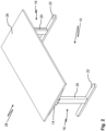
- Figure 1 shows a table frame 10.
- the table frame 10 has a longitudinal beam 12.
- a cross beam 14 of the table frame 10 is arranged at both ends of the longitudinal beam 12.
- a table leg 16 of the table frame 10 is arranged at both ends of the longitudinal beam 12.
- the table legs 16 each have a housing part 18.
- the table legs 16 can each have a column section 20 and a foot section 22.
- the Figure 1 left table leg 16 is shown during its assembly.
- the Figure 1 right table leg 16 and the associated cross member 14 are shown in an assembled state. In the assembled state, the longitudinal member 12 and the two cross members 16 form a contact surface 24 for a table top 26 of a table 28, compare Figure 2 .
- FIGS 3 , 4 and 5 show detailed views of the assembled table frame 10 or the table 28 in the area of the connection of the longitudinal beam 12 with one of the cross beams 14 and one of the table legs 16.
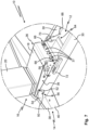
- FIGs 6 and 7 Detailed views of the table frame 10 during the assembly of one of the cross members 14 and one of the table legs 16 to the longitudinal member 12 are shown.
- the longitudinal member 12 has two side walls 30.
- the longitudinal member 12 can be U-shaped in cross section, see Figure 7 .
- the longitudinal beam 12 has two longitudinal beam extensions 32.
- the longitudinal beam extensions 32 each protrude from one of the side walls 30, see in particular Figures 3 and 6 .
- the longitudinal beam extensions 32 are spaced apart from one another transversely to a longitudinal direction of the longitudinal beam 12, see Figure 4
- the longitudinal beam extensions 32 can be formed in one piece with the respective side walls 30.
- the longitudinal beam 12 can be formed in one piece as a whole.
- the housing part 18 has two housing extensions 34.
- the housing part 18 can be box-shaped with two longitudinal walls 36 , see in particular Figures 6 and 7
- the housing extensions 34 can be arranged on the housing part 18 as an extension of the longitudinal walls 36 (in other words, flush with the longitudinal walls 36).
- the housing extensions 34 and the associated longitudinal wall 36 can each be formed integrally with one another.
- a motor (not shown in detail) with electrical connections 37 (see Figure 7 ) for adjusting the length of the respective table leg 16.
- the table legs 16 can be telescopic for this purpose.
- the cross member 14 can have an end wall 38 and a cover wall 40.
- the end wall 38 and the cover wall 40 can extend at right angles to each other.
- the cover wall 40 can also form the contact surface 24 for the table top 26.
- the cover wall 40 of the cross member 14 can have two retaining recesses 42 , see Figures 3 and 6
- Two retaining projections 44 of the longitudinal support 12 can engage in the retaining recesses 42.
- the retaining projections 44 can protrude from the longitudinal support 12, in particular its side walls 30, towards the contact surface 24 for the table top 26 (ie upwards in the position of use).
- the front wall 38 of the cross member 14 has two recesses 46 , see in particular Figure 4 .
- the recesses 46 can be designed as through-holes and can be punched or cut out of the cross member 14, for example.
- the recesses 46 in the cross member 14 could be partially or completely covered and be designed, for example, as impressions (not shown).
- the recesses 46 are each delimited by two opposing edge sections 48a, 48b .
- the edge sections 48a, 48b are each designed to be straight.
- the edge sections 48a, 48b can delimit the recesses 46 upwards or downwards (towards the contact surface 24 for the table top 26 and away from the contact surface 24 for the table top 26).
- the two edge sections 48a, 48b of one of the recesses 46 are each arranged one above the other in the vertical direction.
- edge sections 48a, 48b could be offset from one another laterally (transversely to the longitudinal direction of the longitudinal member 12). It is also conceivable that the edge sections each delimit separate recesses. The two edge sections could delimit a web section of the cross member and be formed in particular on free edges of the cross member (not shown in detail).
- the longitudinal member extensions 32 can first be inserted into the recesses 46. To do this, the cross member 14 can be tilted about its axis relative to the longitudinal member 12. The cross member 14 can then be rotated relative to the longitudinal member 12 into its position shown in the figures, with the retaining projections 44 engaging in the retaining recesses 42.
- the housing extensions 34 of the housing part 18 are inserted into the recesses 46 of the cross member 14 (see in particular Figure 6 ) and the table leg 16 with the housing part 18 is brought into its final position relative to the longitudinal beam 12 (see in particular Figure 3 ).
- the longitudinal beam extensions 32 and the housing extensions 34 rest under pre-tension against the opposite edge sections 48a, 48b of the cross member 14.
- the housing extensions 34 can be pressed against the lower edge sections 48b.
- the longitudinal beam extensions 32 can be pressed against the upper edge sections 48a by mounting the table leg 16.
- the housing extensions 34 and The longitudinal beam extensions 32 are therefore supported on the cross member 14 in opposite directions. As a result, the cross member 14 can be held in a force-fitting manner on the longitudinal beam 12 and the housing part 18.
- the table leg 16 For mounting the table leg 16, it can be pivoted relative to the longitudinal beam 12.
- Two pins 50 are arranged on the housing part 18 (see Figures 3 , 6 and 7 ).
- the side walls 30 of the longitudinal support 12 each have a curved slot 52.
- the pins 50 are first inserted into the open ends 54 of the slots 52.
- the table leg 16 is held at an angle.
- the table leg 16 held at an angle is then pushed forward along the slot 52 until the pins 50 rest against a respective end region 56 of the slots 52 and the housing extensions 34 engage in the recesses 46 of the cross member 14.
- the table leg 16 is now rotated about a pivot axis running through the two pins 50 with the pins 50 resting against the end regions 56 of the slots 52 until it reaches its end position.
- the end position of the table leg 16 relative to the longitudinal beam 12 can be defined by a stop 58.
- the stop 58 is arranged between the housing part 18 and the longitudinal beam 12.
- the stop 58 can be formed with a projection 60 and a recess 62 , see Figures 3 , 6 and 7 .
- the projection 60 can be arranged on the housing part 18.
- the recess 62 can be formed in the side wall 30 of the longitudinal member 12.
- the recess 62 extends here transversely to a longitudinal direction of the longitudinal member 12. Due to the engagement of the projection 60 in the recess 62, the table leg 16 is therefore also positively secured against displacement in the longitudinal direction of the longitudinal member 12, compare Figure 3 .
- a locking element 64 can be rotatable relative to the longitudinal beam 12, see Figure 7
- the locking element 64 can be a bracket.
- two mutually Separate and independently operable locking elements can be provided, which can be mounted opposite one another on the side walls 30 of the longitudinal support 12 (not shown in more detail).
- the locking element 64 is supported on the longitudinal support 12 via a spring element 66, for example a spring wire.
- the housing part 18 of the table leg 16 can have recesses 68. Locking lugs 70 of the locking element 64 are brought into engagement behind the recesses 68 by the spring element 66 when the table leg 16 is in the end position. The locking element 64 with the locking lugs 70 then prevents the table leg 16 from being pivoted back.
- the locking mechanism can be released manually.
- a release lever 72 can interact with the locking element 64.
- the locking element is rotated against the action of the spring element 66, so that the locking lugs 70 are guided out of the recesses 68.
- the table leg 16 can then be rotated about the swivel axis (see pin 50) and guided out of the slots 52 while removing the tension of the edge sections 48a, 48b between the longitudinal support extensions 32 and the housing extensions 34.
Landscapes
- Tables And Desks Characterized By Structural Shape (AREA)
- Furniture Connections (AREA)
Description
- Die Erfindung betrifft ein Tischgestell aufweisend ein Tischbein mit einem Gehäuseteil, einen Längsträger und einen Querträger mit zwei einander gegenüberliegenden Randabschnitten. Die Erfindung betrifft ferner einen Tisch mit einem solchen Tischgestell.
- Ein Tischgestell der eingangs genannten Art ist beispielsweise aus
WO 2019/174686 A2 bekannt. - Bei dem aus
WO 2019/174686 A2 bekannten Tischgestell weist ein Querträger oberseitig an einer Seitenwand einen vorstehenden Flansch und unterseitig eine Halterung auf. Die Halterung besitzt einen rechtwinklig von der Seitenwand abstehenden Abschnitt, welcher an seinem freien Ende in einem hierzu rechtwinkligen Flansch endet. Die Seitenwand des Querträgers weist beidseits der Halterung Schlitze auf. Zur Montage des Querträgers an einem Längsträger wird der rechtwinklige Flansch der Halterung in einen Querschlitz an der Unterseite des Längsträgers eingeführt, während die Schlitze in der Seitenwand des Querträgers vorstehende Flansche an Seitenwänden des Längsträgers übergreifen. - Ein Tischbein des aus
WO 2019/174686 A2 bekannten Tischgestells weist eine U-förmige Montageklammer auf, in welcher der Längsträger aufgenommen werden kann. Der Längsträger weist außenseitig ein Paar Achsstümpfe auf, die mit Rücknehmungen am innenseitigen Ende der Montageklammer des Tischbeins zusammenwirken. Um das Tischbein am Längsträger zu fixieren, greifen zwei federbelastete Klinken aus dem Längsträger in zwei Schlitze der Montageklammer ein. -
WO 2018/093323 A1 beschreibt ein zusammenklappbares Tischgestell mit zwei Tischbeinen, einem Längsträger sowie zwei Querträgern. Die Tischbeine umfassen Antriebseinheiten, die an dem Längsträger schwenkbar gelagert sind. In die Antriebseinheiten sind Schrauben eingeschraubt, welche im aufgerichteten Zustand des Tischgestells Rücksprünge an Haken des Längsträgers durchragen. Der Querträger weist Montageabschnitte mit Schlitzen auf. Zur Montage an dem Längsträger wird der Querträger auf den Längsträger aufgeschoben, sodass die Schrauben auch die Schlitze durchragen. Am geschlossenen Ende der Schlitze sind Senkungen vorgesehen, in welche beim Anziehen der Schrauben deren Köpfe eingreifen. - Aus
DE 20 2011 002 647 U1 ist ein Tisch mit mindestens einer vertikalen Tragsäule und einer von dieser getragenen Tischplatte bekannt, wobei auf der Tragsäule eine horizontale Flanschplatte angeordnet ist, auf der mindestens ein als Hohlprofil ausgebildeter Tragholm gehalten ist, der ein freies Ende aufweist, in das ein Klemmelement eingesetzt ist, wobei das Klemmelement mit einem die Tischplatte haltenden Plattenträger verbunden und mit Gewindebohrungen versehen ist, in die die Flanschplatte von unten durchgreifende und den Tragholm an der Flanschplatte fixierende Befestigungsschrauben eingreifen. - Es ist eine Aufgabe der Erfindung, die Montage eines Tisches mit einem Tischgestell einfach und zuverlässig zu gestalten.
- Diese Aufgabe wird erfindungsgemäß gelöst durch ein Tischgestell gemäß Anspruch 1 und einen Tisch gemäß Anspruch 15. In den Unteransprüchen sind vorteilhafte Ausführungsformen angegeben.
- Erfindungsgemäß ist ein Tischgestell vorgesehen. Das Tischgestell weist ein Tischbein mit einem Gehäuseteil auf. Das Tischgestell weist ferner einen Längsträger auf. Der Längsträger erstreckt sich typischerweise in einer Längsrichtung von dem Tischbein zu einem weiteren Tischbein des Tischgestells. Weiterhin weist das Tischgestell einen Querträger mit zwei einander gegenüberliegenden Randabschnitten auf. Das Gehäuseteil des Tischbeins dient zur Verbindung des Tischbeins mit dem Längsträger und dem Querträger. Das Gehäuseteil kann im montierten Zustand den Längsträger übergreifen und/oder in den Längsträger eingreifen. Der Querträger und das Tischbein sind typischerweise an einem Ende des Längsträgers angeordnet.
- Im montierten Zustand des Tischgestells ist oberseitig auf dem Querträger und/oder dem Längsträger eine Tischplatte anordenbar. Der Längsträger und der Querträger können (im montierten Zustand des Tischgestells) gemeinsam eine Anlagefläche für die Tischplatte ausbilden.
- Richtungsangaben wie beispielsweise oben oder unten beziehen sich für die Beschreibung der vorliegenden Erfindung auf eine Gebrauchsstellung des Tischgestells bzw. eines Tisches mit dem Tischgestell.
- Erfindungsgemäß ist vorgesehen, dass an einem der Randabschnitte des Querträgers ein Längsträgerfortsatz des Längsträgers und an dem anderen Randabschnitt ein Gehäusefortsatz des Gehäuseteils unter Vorspannung zur Anlage bringbar sind.
- Zur Montage des Tischgestells können der Längsträger, der Querträger und das Tischbein zunächst in einen Montagezwischenzustand gebracht werden, in dem die vorgenannten Bauteile relativ zueinander vorpositioniert sind. Vorteilhafterweise können der Längsträger, der Querträger und das Tischbein dabei relativ zueinander ausgerichtet werden, ohne dass hierzu ein besonderer Kraftaufwand erforderlich wäre. Ferner kann der Montagezwischenzustand vorteilhafterweise ohne Werkzeug eingerichtet werden.
- Im montierten Zustand des Tischgestells liegen der Längsträgerfortsatz und der Gehäusefortsatz unter Vorspannung an den einander gegenüberliegenden Randabschnitten des Querträgers an. Mit anderen Worten ist der Querträger über den Längsträgerfortsatz und den Gehäusefortsatz mit dem Längsträger und dem Tischbein verspannt. Durch die Vorspannung bzw. das Verspannen ist der Querträger an dem Längsträger und dem Tischbein gehalten. Das Tischgestell kann dann, beispielsweise zur Montage einer Tischplatte, gehandhabt werden, ohne dass sich der Querträger von dem Längsträger lösen kann. Auch um den Querträger mit dem Längsträgerfortsatz und dem Querträgerfortsatz zu verspannen, ist vorteilhafterweise kein Werkzeug erforderlich.
- Der Längsträgerfortsatz erstreckt sich typischerweise in einer Längsrichtung des Längsträgers von einem Zentralabschnitt des Längsträgers weg. Im montierten Zustand kann sich der Gehäusefortsatz im Wesentlichen parallel zu dem Längsträgerfortsatz erstrecken. Typischerweise ragt der Gehäusefortsatz senkrecht zu einer (in der Gebrauchsstellung vertikalen) Beinachse des Tischbeins von dem Gehäuseteil ab.
- Die beiden Randabschnitte können sich geradlinig erstrecken. Typischerweise verlaufen die beiden Randabschnitte in der Gebrauchsstellung des Tischgestells in horizontaler Richtung. Alternativ können die Randabschnitte gekrümmt ausgebildet sein. Insbesondere können die Randabschnitte zu dem jeweiligen Fortsatz hin konkav ausgebildet sein.
- Weiter erfindungsgemäß begrenzen die beiden Randabschnitte gemeinsam eine Ausnehmung in dem Querträger. Mit anderen Worten begrenzen die beiden Randabschnitte des Querträgers dieselbe Ausnehmung. Die Ausnehmung kann von weiteren Randbereichen des Querträgers begrenzt sein. Im montierten Zustand greifen der Längsträgerfortsatz und der Gehäusefortsatz (auch gemeinsam als die Fortsätze bezeichnet) in die Ausnehmung ein. Vorzugsweise durchragen der Längsträgerfortsatz und/oder der Gehäusefortsatz die Ausnehmung. Durch Einbringen der Ausnehmung in den Querträger können die Randabschnitte in einfacher Weise und präzise am Querträger vorgesehen werden. Das Eingreifen der Fortsätze in die Ausnehmung kann zudem die Montage weiter vereinfachen. Insbesondere kann der Querträger bereits im Montagezwischenzustand von einem der Fortsätze, insbesondere dem Längsträgerfortsatz, gehalten sein.
- Der Längsträgerfortsatz und/oder der Gehäusefortsatz können einen Hakenabschnitt aufweisen. Der Hakenabschnitt kann den jeweils zugeordneten Randabschnitt des Querträgers hintergreifen. Der Querträger kann dann besonders sicher gehalten werden.
- Der Längsträger kann einen Haltevorsprung zum Eingreifen in eine Halteausnehmung des Querträgers aufweisen. Der Haltevorsprung erstreckt sich vorteilhafterweise quer zu dem Längsträgerfortsatz. Vorzugsweise ragt der Haltevorsprung zu einer Anlagefläche für eine Tischplatte hin. Mit anderen Worten kann der Haltevorsprung nach oben bzw. von dem Tischbein weg von dem Längsträger abragen. Durch den Eingriff des Haltevorsprungs in die Halteausnehmung ist der Querträger besonders sicher am Längsträger gehalten.
- Bei einer besonders bevorzugten Ausführungsform des Tischgestells ist das Tischbein gegenüber dem Längsträger schwenkbar. Somit kann das Tischbein zur Montage gegenüber dem Längsträger gedreht (geschwenkt) werden. Durch Schwenken des Tischbeins kann der Querträger auf besonders einfache Weise zwischen dem Längsträgerfortsatz und dem Gehäusefortsatz verspannt werden. Zudem kann durch die Schwenkbewegung eine Hebelwirkung erzielt werden, welche die Anlagekräfte der Fortsätze an den Randabschnitten erhöht. Dadurch ist der Querträger im montierten Zustand noch zuverlässiger gehalten.
- Eine Schwenkachse zwischen dem Längsträger und dem Tischbein kann mit einem Zapfen gebildet sein. Der Zapfen kann einerseits die Schwenkachse definieren. Andererseits kann der Zapfen als Widerlager zur Abstützung des Längsträgers an dem Tischbein dienen. Vorzugsweise ist der Zapfen an dem Gehäuseteil des Tischbeins angeordnet. Der Zapfen kann beispielsweise durch einen Niet oder eine Schraube gebildet sein. Dies vereinfacht die Fertigung.
- Ein Endbereich eines Schlitzes kann zur Anlage des Zapfens dienen. Anderends ist der Schlitz grundsätzlich offen. Bei der Montage wird der Zapfen zunächst in den Schlitz eingeführt und sodann zu dem (geschlossenen) Endbereich vorgeschoben. Wenn der Zapfen den Endbereich erreicht hat, werden das Tischbein und der Längsträger gegeneinander verschwenkt bis das Tischbein eine Endlage erreicht. Derart kann die Montage besonders einfach und insbesondere ohne Werkzeug erfolgen. Im montierten Zustand verbleibt der Zapfen vorteilhafterweise in dem Endbereich. Im montierten Zustand befindet sich das Tischbein grundsätzlich in der Endlage relativ zum Längsträger.
- Der Schlitz kann gebogen sein. Dadurch kann erreicht werden, dass der Zapfen sich bei Belastung, insbesondere bei Belastung durch die Vorspannkraft am Gehäusefortsatz, im Wesentlichen orthogonal am Rand des Schlitzes abstützt. Es kann mithin vermieden werden, dass sich der Zapfen bei Belastung im Schlitz bewegt und von dem Endbereich entfernt.
- Vorzugsweise ist der Schlitz in einer Seitenwand des Längsträgers ausgebildet. Dies vereinfacht die Fertigung. Der Schlitz kann beispielsweise durch Stanzen oder Laserschneiden erhalten sein.
- Vorzugsweise ist zwischen dem Gehäuseteil und dem Längsträger ein Anschlag für die Schwenkbewegung eingerichtet. Der Anschlag kann einerseits sicherstellen, dass das Tischbein sich im montierten Zustand in einer Endlage (entsprechend einer Funktionsstellung), typischerweise rechtwinklig zum Längsträger, befindet. Andererseits kann der Anschlag den Betrag der von den Fortsätzen ausgeübten Vorspannkraft bestimmen.
- Der Anschlag kann mit einem Vorsprung und einer Rücknehmung gebildet sein. Insbesondere wenn die Rücknehmung sich quer zur Längsrichtung des Längsträger erstreckt, kann der Anschlag gleichzeitig auch eine Längsposition des Tischbeins relativ zum Längsträger sichern. Wenn die Schwenkachse durch die Anlage eines Zapfens an einem Endbereich eines Schlitzes eingerichtet ist, kann der in die Rücknehmung eingreifende Vorsprung sicherstellen, dass der Zapfen im montierten Zustand in dem Endbereich des Schlitzes verbleibt.
- Vorzugsweise ist die Rücknehmung in einer Seitenwand des Längsträgers ausgebildet, beispielsweise in die Seitenwand gestanzt oder geschnitten. Der Vorsprung kann durch einen Niet oder eine Schraube gebildet sein. Dies vereinfacht die Fertigung weiter. Wenn der Vorsprung durch eine Schraube gebildet ist, kann durch Anziehen der Schraube die Endstellung der Schwenkbewegung gesichert werden.
- Vorzugsweise ist das Tischbein an dem Längsträger verrastbar. Durch das Verrasten kann das Tischbein in seiner für den Gebrauch des Tischgestells erforderlichen Stellung (insbesondere einer Endlage einer Schwenkbewegung) am Längsträger fixiert werden. Im verrasteten (d. h. montierten) Zustand des Tischbeins liegen der Längsträgerfortsatz und der Gehäusefortsatz unter Vorspannung an den Randabschnitten des Querträgers an. Eine Verrastung kann besonders einfach, insbesondere ohne Werkzeug, eingerichtet werden. Zur Demontage des Tischgestells kann die Verrastung durch geeignete Manipulation lösbar sein.
- Zum Verrasten des Tischbeins kann ein Rastelement drehbar an dem Längsträger gehalten sein. Vorzugsweise stützt sich das Rastelement über ein Federelement an dem Längsträger ab. Das Rastelement kann ein Bügel sein. Derart kann eine zuverlässige Rastmechanik mit geringem fertigungstechnischen Aufwand eingerichtet werden. Insbesondere kann ein als Bügel ausgebildetes Rastelement die Zugänglichkeit von elektrischen Anschlüssen eines in dem Gehäuseteil angeordneten Motors zur Längenverstellung des Tischbeins gewährleisten. Zudem kann ein drehbares Rastelement zum Lösen der Verrastung auf einfache Weise manuell entgegen der Federwirkung ausgelenkt werden. Hierzu kann ein Auslösehebel an dem Rastelement vorgesehen sein.
- Das Gehäuseteil kann einen Rücksprung zum Hintergreifen mit einer Rastnase aufweisen. Dies kann im Hinblick auf die Steifigkeit der verrasteten Verbindung des Gehäuseteils mit dem Längsträger vorteilhaft sein. Die Rastnase ist vorzugsweise an einem drehbar an dem Längsträger gehaltenen Rastelement, insbesondere in Form eines Bügels, ausgebildet.
- Der Gehäusefortsatz kann den Querträger von einer Anlagefläche für eine Tischplatte weg vorspannen. Mit anderen Worten kann der Gehäusefortsatz den Querträger nach unten spannen. Wenn das Tischbein gegenüber dem Längsträger schwenkbar ist, kann eine Schwenkachse hierzu in einem lateral äußeren Bereich des Längsträgers und des Gehäuseteils angeordnet sein. Wenn der Gehäusefortsatz den Querträger von der Anlagefläche weg spannt, spannt der Längsträgerfortsatz den Querträger zu der Anlagefläche hin (nach oben). Wenn der Längsträger einen nach oben ragenden Haltevorsprung aufweist, kann der Querträger dann im Wesentlichen widerstandslos auf dem Längsträger angeordnet werden. Der Querträger kann hierzu am Längsträgerfortsatz angesetzt werden und sodann geschwenkt werden, um den Haltevorsprung in Eingriff mit der Halteausnehmung zu bringen. Daraufhin wird der Querträger mittels des Gehäusefortsatzes fixiert (z. B. durch Schwenken des Tischbeins in seine Endlage). Die Montage kann somit einfach und mit geringem Kraftaufwand erfolgen.
- Das Tischbein kann längenverstellbar sein. Über die Längenverstellung des Tischbeins kann eine Höhe eines Tisches mit dem Tischgestell eingestellt werden.
- Vorzugsweise ist in dem Gehäuseteil ein Motor zur Längenverstellung des Tischbeins angeordnet. Das Gehäuseteil dient dann einerseits zur Verbindung des Tischbeins, des Längsträgers und des Querträgers miteinander. Andererseits dient das Gehäuseteil auch zur Aufnahme und Abstützung des Motors. Es kann somit eine kompakte Konstruktion mit geringem Materialeinsatz erhalten werden.
- Vorzugsweise ist vorgesehen, dass der Querträger zwei weitere einander gegenüberliegende Randabschnitte aufweist, und dass an einem der weiteren Randabschnitte ein weiterer Längsträgerfortsatz des Längsträgers und an dem anderen weiteren Randabschnitt ein weiterer Gehäusefortsatz des Gehäuseteils unter Vorspannung zur Anlage bringbar sind. Durch die weiteren Fortsätze kann der Querträger besonders zuverlässig gehalten werden. Die weiteren Fortsätze sind typischerweise quer zu einer Längsrichtung des Längsträgers von den (ersten) Fortsätzen beabstandet. Die weiteren Fortsätze sind typischerweise wie die (ersten) Fortsätze ausgebildet.
- Ein weiteres Tischbein und ein weiterer Querträger können wie das (erste) Tischbein und der (erste) Querträger ausgebildet und mit dem Längsträger verbindbar sein. Der weitere Querträger und das weitere Tischbein sind grundsätzlich an einem zweiten Ende des Längsträgers angeordnet. Durch das weitere Tischbein kann die Standsicherheit des Tisches verbessert werden. Der weitere Querträger kann die Abstützung einer Tischplatte an dem Tischgestell verbessern.
- In den Rahmen der vorliegenden Erfindung fällt ferner ein Tisch mit einer Tischplatte und einem oben beschriebenen, erfindungsgemäßen Tischgestell. Im montierten Zustand kann die Tischplatte an dem Querträger bzw. den Querträgern und/oder an dem Längsträger befestigt sein. Durch die oben beschriebenen Vorteile bei der Montage des erfindungsgemäßen Tischgestells kann dieses unabhängig von der Tischplatte (vor)montiert werden. Sodann kann die Tischplatte an dem Tischgestell befestigt werden. Insbesondere kann hierzu das Tischgestell auf die (mit ihrer Oberseite nach unten) liegende Tischplatte aufgesetzt und in geeigneter Weise mit ihr verbunden werden. Durch die Verspannung des Querträgers bzw. der Querträger besteht dabei nicht die Gefahr, dass sich dieser bzw. diese während der Handhabung des vormontierten Tischgestells von dem Längsträger lösen.
- Weitere Merkmale und Vorteile der Erfindung ergeben sich aus der Beschreibung und der Zeichnung. Erfindungsgemäß können die vorstehend genannten und die noch weiter ausgeführten Merkmale jeweils einzeln für sich oder zu mehreren in beliebigen, zweckmäßigen Kombinationen Verwendung finden. Die gezeigten und beschriebenen Ausführungsformen sind nicht als abschließende Aufzählung zu verstehen, sondern haben vielmehr beispielhaften Charakter für die Schilderung der Erfindung.
- Die Erfindung ist in der Zeichnung dargestellt und wird anhand eines Ausführungsbeispiels näher erläutert. Es zeigen:
- Fig. 1
- ein erfindungsgemäßes Tischgestell aufweisend einen Längsträger, zwei Tischbeine mit je einem Gehäuseteil und zwei Querträger, wobei sich eines der Tischbeine in einem montierten Zustand befindet und sich das andere Tischbein in einem Zwischenzustand während seiner Montage befindet, in einer schematischen Seitenansicht;
- Fig. 2
- einen erfindungsgemäßen Tisch mit einer Tischplatte, die auf dem Tischgestell von
Figur 1 gehalten ist, in einer schematischen Perspektivansicht; - Fig. 3
- eine vergrößerte schematische Seitenansicht des Tisches von
Figur 2 im Bereich der Verbindung des Längsträgers mit einem der Querträger und einem der Tischbeine; - Fig. 4
- den Tisch von
Figur 2 in einer vergrößerten schematischen Detailansicht mit Blick auf eine Stirnseite, an welcher einer der Querträger verläuft, wobei zu erkennen ist, dass zwei Längsträgerfortsätze und zwei Gehäusefortsätze jeweils an einander gegenüberliegenden Randabschnitten zweier Ausnehmungen in dem Querträger anliegen; - Fig. 5
- einen weiteren vergrößerten schematischen Ausschnitt aus
Figur 4 im Bereich einer der erfindungsgemäßen Ausnehmungen in dem Querträger, in welche einer der Längsträgerfortsätze und einer der Gehäusefortsätze eingreifen; - Fig. 6
- eine vergrößerte schematische Seitenansicht des Tischgestells von
Figur 1 während der Montage eines der Tischbeine, wobei ein an einem Endbereich eines Schlitzes anliegender Zapfen eine Schwenkachse für das Tischbein bildet und wobei der Längsträgerfortsatz und der Gehäusefortsatz den Querträger durchragen; - Fig. 7
- eine schematische Perspektivansicht der Anordnung von
Figur 6 , wobei eine Rastmechanik mit einem federbelasteten Rastelement in Form eines Bügels und mit Rücksprüngen am Gehäuseteil zu erkennen ist. -
Figur 1 zeigt ein Tischgestell 10. Das Tischgestell 10 weist einen Längsträger 12 auf. Beidenends an dem Längsträger 12 ist je ein Querträger 14 des Tischgestells 10 angeordnet. Ferner ist an beiden Enden des Längsträgers 12 je ein Tischbein 16 des Tischgestells 10 angeordnet. Die Tischbeine 16 weisen jeweils ein Gehäuseteil 18 auf. Ferner können die Tischbeine 16 jeweils einen Säulenabschnitt 20 und einen Fußabschnitt 22 aufweisen. Das inFigur 1 linke Tischbein 16 ist während seiner Montage gezeigt. Das inFigur 1 rechte Tischbein 16 und der zugehörige Querträger 14 sind in einem montierten Zustand gezeigt. Im montierten Zustand bilden der Längsträger 12 und die beiden Querträger 16 eine Anlagefläche 24 für eine Tischplatte 26 eines Tisches 28, vergleicheFigur 2 . - Die
Figuren 3 ,4 und 5 zeigen Detailansichten des montierten Tischgestells 10 bzw. des Tisches 28 im Bereich der Verbindung des Längsträgers 12 mit einem der Querträger 14 und einem der Tischbeine 16. In denFiguren 6 und7 sind Detailansichten des Tischgestells 10 während der Montage eines der Querträger 14 und eines der Tischbeine 16 an dem Längsträger 12 gezeigt. - Der Längsträger 12 weist vorliegend zwei Seitenwände 30 auf. Insbesondere kann der Längsträger 12 im Querschnitt U-förmig ausgebildet sein, vergleiche
Figur 7 . Der Längsträger 12 weist zwei Längsträgerfortsätze 32 auf. Die Längsträgerfortsätze 32 ragen jeweils von einer der Seitenwände 30 ab, vergleiche insbesondereFiguren 3 und6 . Quer zu einer Längsrichtung des Längsträgers 12 sind die Längsträgerfortsätze 32 voneinander beabstandet, vergleicheFigur 4 . Die Längsträgerfortsätze 32 können einstückig mit den jeweiligen Seitenwänden 30 ausgebildet sein. Insbesondere kann der Längsträger 12 insgesamt einstückig ausgebildet sein. - Das Gehäuseteil 18 weist zwei Gehäusefortsätze 34 auf. Das Gehäuseteil 18 kann kastenförmig mit zwei Längswänden 36 ausgebildet sein, vergleiche insbesondere
Figuren 6 und7 . Die Gehäusefortsätze 34 können in Verlängerung der Längswände 36 (mit anderen Worten bündig mit den Längswänden 36) an dem Gehäuseteil 18 angeordnet sein. Die Gehäusefortsätze 34 und die zugeordnete Längswand 36 können jeweils einstückig miteinander ausgebildet sein. - In den Gehäuseteilen 18 kann jeweils ein nicht näher dargestellter Motor mit elektrischen Anschlüsse 37 (vergleiche
Figur 7 ) zur Längenverstellung des jeweiligen Tischbeins 16 angeordnet sein. Die Tischbeine 16 können hierzu teleskopierbar sein. - Der Querträger 14 kann eine Stirnwand 38 und eine Deckwand 40 aufweisen. Die Stirnwand 38 und die Deckwand 40 können sich rechtwinklig zueinander erstrecken. Die Deckwand 40 kann die Anlagefläche 24 für die Tischplatte 26 mit ausbilden.
- Die Deckwand 40 des Querträgers 14 kann zwei Halteausnehmungen 42 aufweisen, vergleiche
Figuren 3 und6 . Zwei Haltevorsprünge 44 des Längsträgers 12 können in die Halteausnehmungen 42 eingreifen. Die Haltevorsprünge 44 können von dem Längsträger 12, insbesondere dessen Seitenwänden 30, zu der Anlagefläche 24 für die Tischplatte 26 hin (d. h. in der Gebrauchsstellung nach oben) ragen. - Die Stirnwand 38 des Querträgers 14 weist vorliegend zwei Ausnehmungen 46 auf, vergleiche insbesondere
Figur 4 . Die Ausnehmungen 46 können als Durchgangsausnehmungen ausgebildet und beispielsweise aus dem Querträger 14 ausgestanzt oder ausgeschnitten sein. Alternativ könnten die Ausnehmungen 46 in dem Querträger 14 bereichsweise oder vollständig überdeckt sein und beispielsweise als Einprägungen ausgebildet sein (nicht dargestellt). - Die Ausnehmungen 46 werden jeweils von zwei einander gegenüberliegenden Randabschnitten 48a, 48b begrenzt. Die Randabschnitte 48a, 48b sind hier jeweils geradlinig ausgebildet. Die Randabschnitte 48a, 48b können die Ausnehmungen 46 nach oben bzw. unten (zu der Anlagefläche 24 für die Tischplatte 26 hin und von der Anlagefläche 24 für die Tischplatte 26 weg) begrenzen. Die beiden Randabschnitte 48a, 48b einer der Ausnehmungen 46 sind hier jeweils in vertikaler Richtung übereinanderliegend angeordnet.
- Bei einer nicht näher dargestellten Ausführungsform könnten die Randabschnitte 48a, 48b seitlich (quer zur Längsrichtung des Längsträgers 12) gegeneinander versetzt sein. Es ist auch denkbar, dass die Randabschnitte jeweils separate Ausnehmungen begrenzen. Die beiden Randabschnitte könnten einen Stegabschnitt des Querträgers begrenzen und insbesondere an freien Rändern des Querträgers ausgebildet sein (nicht näher dargestellt).
- Zur Montage des Querträgers 14 an dem Längsträger 12 können zunächst die Längsträgerfortsätze 32 in die Ausnehmungen 46 eingeführt werden. Hierzu kann der Querträger 14 um seine Achse gegenüber dem Längsträger 12 gekippt werden. Sodann kann der Querträger 14 relativ zu dem Längsträger 12 in seine in den Figuren gezeigte Lage gedreht werden, wobei die Haltevorsprünge 44 in die Halteausnehmungen 42 eingreifen.
- Um den Querträger 14 an dem Längsträger 12 zu fixieren, werden die Gehäusefortsätze 34 des Gehäuseteils 18 in die Ausnehmungen 46 des Querträgers 14 eingeführt (vergleiche insbesondere
Figur 6 ) und das Tischbein 16 mit dem Gehäuseteil 18 wird in seine Endlage relativ zu dem Längsträger 12 gebracht (vergleiche insbesondereFigur 3 ). In dieser Endlage bzw. einem montierten Zustand liegen die Längsträgerfortsätze 32 und die Gehäusefortsätze 34 unter Vorspannung an den gegenüberliegenden Randabschnitten 48a, 48b des Querträgers 14 an. Durch die Montage des Tischbeins 16 können die Gehäusefortsätze 34 gegen die unteren Randabschnitte 48b gepresst werden. Die Längsträgerfortsätze 32 können durch die Montage des Tischbeins 16 gegen die oberen Randabschnitte 48a gepresst werden. Die Gehäusefortsätze 34 und die Längsträgerfortsätze 32 stützen sich mithin in einander entgegengesetzten Richtungen an dem Querträger 14 ab. Dadurch kann der Querträger 14 kraftschlüssig an dem Längsträger 12 und dem Gehäuseteil 18 gehalten werden. - Für die Montage des Tischbeins 16 kann dieses gegenüber dem Längsträger 12 geschwenkt werden. An dem Gehäuseteil 18 sind hier zwei Zapfen 50 angeordnet (vergleiche
Figuren 3 ,6 und7 ). Die Seitenwände 30 des Längsträgers 12 weisen jeweils einen gebogenen Schlitz 52 auf. Bei der Montage des Tischbein 16 werden zunächst die Zapfen 50 in offene Enden 54 der Schlitze 52 eingeführt. Hierbei wird das Tischbein 16 schräg gehalten. Das schräg gehaltene Tischbein 16 wird sodann entlang der Schlitz 52 vorgeschoben, bis die Zapfen 50 an einem jeweiligen Endbereich 56 der Schlitze 52 anliegen und die Gehäusefortsätze 34 in die Ausnehmungen 46 des Querträgers 14 eingreifen. Nun wird das Tischbein 16 unter Anlage der Zapfen 50 an den Endbereichen 56 der Schlitze 52 um eine durch die beiden Zapfen 50 verlaufende Schwenkachse gedreht bis es seine Endlage erreicht. - Die Endlage des Tischbein 16 relativ zu dem Längsträger 12 kann durch einen Anschlag 58 definiert sein. Vorzugsweise ist der Anschlag 58 zwischen dem Gehäuseteil 18 und dem Längsträger 12 eingerichtet. Der Anschlag 58 kann mit einem Vorsprung 60 und einer Rücknehmung 62 gebildet sein, vergleiche
Figuren 3 ,6 und7 . Der Vorsprung 60 kann an dem Gehäuseteil 18 angeordnet sein. Die Rücknehmung 62 kann in der Seitenwand 30 des Längsträgers 12 ausgebildet sein. Die Rücknehmung 62 erstreckt sich hier quer zu einer Längsrichtung des Längsträgers 12. Durch den Eingriff des Vorsprungs 60 in die Rücknehmung 62 ist das Tischbein 16 daher auch gegen Verschieben in der Längsrichtung des Längsträgers 12 formschlüssig an diesem gesichert, vergleicheFigur 3 . - Um das Tischbein 16 in der durch den Anschlag 58 definierten Endlage zu halten, kann das Tischbein 16 an dem Längsträger 12 verrastbar sein. Ein Rastelement 64 kann gegenüber dem Längsträger 12 drehbar sein, vergleiche
Figur 7 . Das Rastelement 64 kann ein Bügel sein. Alternativ können zwei voneinander getrennte und unabhängig voneinander bedienbare Rastelemente vorgesehen sein, die einander gegenüberliegend an den Seitenwänden 30 des Längsträgers 12 gelagert sein können (nicht näher dargestellt). Vorliegend ist das Rastelement 64 über ein Federelement 66, beispielsweise einen Federdraht, an dem Längsträger 12 abgestützt. Das Gehäuseteil 18 des Tischbeins 16 kann Rücksprünge 68 aufweisen. Rastnasen 70 des Rastelements 64 werden durch das Federelement 66 in Hintergriff hinter die Rücksprünge 68 gebracht, wenn sich das Tischbein 16 in der Endlage befindet. Das Rastelement 64 mit den Rastnasen 70 verhindert dann, dass das Tischbein 16 zurückgeschwenkt wird. - Um das Tischbein 16 zur Demontage zurückschwenken zu können, kann die Verrastung manuell gelöst werden. Hierzu kann ein Auslösehebel 72 mit dem Rastelement 64 zusammenwirken. Durch Betätigen des Auslösehebels 72 wird das Rastelement gegen die Wirkung des Federelements 66 gedreht, sodass die Rastnasen 70 aus den Rücksprüngen 68 herausgeführt werden. Das Tischbein 16 kann sodann unter Aufhebung der Verspannung der Randabschnitte 48a, 48b zwischen den Längsträgerfortsätzen 32 und den Gehäusefortsätzen 34 um die Schwenkachse (vergleiche Zapfen 50) gedreht und aus den Schlitzen 52 herausgeführt werden.
-
- Tischgestell 10
- Längsträger 12
- Querträger 14
- Tischbein 16
- Gehäuseteil 18
- Säulenabschnitt 20
- Fußabschnitt 22
- Anlagefläche 24
- Tischplatte 26
- Tisch 28
- Seitenwand 30
- Längsträgerfortsatz 32
- Gehäusefortsatz 34
- Längswand 36
- Anschlüsse 37
- Stirnwand 38
- Deckwand 40
- Halteausnehmung 42
- Haltevorsprung 44
- Ausnehmung 46
- Randabschnitte 48a, 48b
- Zapfen 50
- Schlitz 52
- offenes Ende 54
- Endbereich 56
- Anschlag 58
- Vorsprung 60
- Rücknehmung 62
- Rastelement 64
- Federelement 66
- Rücksprung 68
- Rastnase 70
- Auslösehebel 72
Claims (15)
- Tischgestell (10) aufweisend ein Tischbein (16) mit einem Gehäuseteil (18), einen Längsträger (12) und einen Querträger (14) mit zwei einander gegenüberliegenden Randabschnitten (48a, 48b), die eine Ausnehmung (46) in dem Querträger (14) begrenzen, wobei an einem der Randabschnitte (48a) ein Längsträgerfortsatz (32) des Längsträgers (12) und an dem anderen Randabschnitt (48b) ein Gehäusefortsatz (34) des Gehäuseteils (18) unter Vorspannung zur Anlage bringbar sind, wobei der Längsträgerfortsatz (32) und der Gehäusefortsatz (34) in die Ausnehmung (46) eingreifen.
- Tischgestell (10) nach Anspruch 1, dadurch gekennzeichnet, dass das Gehäuseteil (18) kastenförmig mit zwei Längswänden (36) und zwei Gehäusefortsätzen (34) ausgebildet ist, wobei die Gehäusefortsätze (34) und die zugeordnete Längswand (36) jeweils einstückig miteinander ausgebildet sind.
- Tischgestell (10) nach einem der vorhergehenden Ansprüche, dadurch gekennzeichnet, dass der Längsträger (12) einen Haltevorsprung (44) zum Eingreifen in eine Halteausnehmung (42) des Querträgers (14) aufweist, vorzugsweise wobei der Haltevorsprung (44) zu einer Anlagefläche (24) für eine Tischplatte (26) hin ragt.
- Tischgestell (10) nach einem der vorhergehenden Ansprüche, dadurch gekennzeichnet, dass das Tischbein (16) gegenüber dem Längsträger (12) schwenkbar ist.
- Tischgestell (10) nach Anspruch 4, dadurch gekennzeichnet, dass eine Schwenkachse mit einem Zapfen (50) gebildet ist, vorzugsweise wobei der Zapfen (50) am Gehäuseteil (18) des Tischbeins (16) angeordnet ist.
- Tischgestell (10) nach Anspruch 5, dadurch gekennzeichnet, dass ein Endbereich (56) eines, insbesondere gebogenen, Schlitzes (52) zur Anlage des Zapfens (50) dient, vorzugsweise wobei der Schlitz (52) in einer Seitenwand (30) des Längsträgers (12) ausgebildet ist.
- Tischgestell (10) nach einem der Ansprüche 4 bis 6, dadurch gekennzeichnet, dass zwischen dem Gehäuseteil (18) und dem Längsträger (12) ein Anschlag (58) für die Schwenkbewegung eingerichtet ist.
- Tischgestell (10) nach Anspruch 7, dadurch gekennzeichnet, dass der Anschlag (58) mit einem Vorsprung (60) und einer Rücknehmung (62) gebildet ist.
- Tischgestell (10) nach einem der vorhergehenden Ansprüche, dadurch gekennzeichnet, dass der Gehäusefortsatz (34) den Querträger (14) von einer Anlagefläche (24) für eine Tischplatte (26) weg vorspannt.
- Tischgestell (10) nach einem der vorhergehenden Ansprüche, dadurch gekennzeichnet, dass das Tischbein (16) an dem Längsträger (12) verrastbar ist.
- Tischgestell (10) nach Anspruch 10, dadurch gekennzeichnet, dass zum Verrasten des Tischbeins (16) ein Rastelement (64), insbesondere ein Bügel, drehbar an dem Längsträger (12) gehaltenen ist, vorzugsweise wobei sich das Rastelement (64) über ein Federelement (66) an dem Längsträger (12) abstützt.
- Tischgestell (10) nach Anspruch 10 oder 11, dadurch gekennzeichnet, dass das Gehäuseteil (18) einen Rücksprung (68) zum Hintergreifen mit einer Rastnase (70) aufweist.
- Tischgestell (10) nach einem der vorhergehenden Ansprüche, dadurch gekennzeichnet, dass in dem Gehäuseteil (18) ein Motor zur Längenverstellung des Tischbeins (16) angeordnet ist.
- Tischgestell (10) nach einem der vorhergehenden Ansprüche, dadurch gekennzeichnet, dass der Querträger (14) zwei weitere einander gegenüberliegende Randabschnitte (48a, 48b) aufweist, und dass an einem der weiteren Randabschnitte (48a) ein weiterer Längsträgerfortsatz (32) des Längsträgers (12) und an dem anderen weiteren Randabschnitt (48b) ein weiterer Gehäusefortsatz (34) des Gehäuseteils (18) unter Vorspannung zur Anlage bringbar sind.
- Tisch (28) mit einer Tischplatte (26) und einem Tischgestell (10) nach einem der vorhergehenden Ansprüche.
Applications Claiming Priority (2)
| Application Number | Priority Date | Filing Date | Title |
|---|---|---|---|
| DE102020211087.5A DE102020211087A1 (de) | 2020-09-02 | 2020-09-02 | Tischgestell und Tisch |
| PCT/EP2021/072778 WO2022048903A1 (de) | 2020-09-02 | 2021-08-17 | Tischgestell und tisch |
Publications (3)
| Publication Number | Publication Date |
|---|---|
| EP4175511A1 EP4175511A1 (de) | 2023-05-10 |
| EP4175511C0 EP4175511C0 (de) | 2024-07-24 |
| EP4175511B1 true EP4175511B1 (de) | 2024-07-24 |
Family
ID=77520751
Family Applications (1)
| Application Number | Title | Priority Date | Filing Date |
|---|---|---|---|
| EP21762470.9A Active EP4175511B1 (de) | 2020-09-02 | 2021-08-17 | Tischgestell und tisch |
Country Status (4)
| Country | Link |
|---|---|
| US (1) | US20230210252A1 (de) |
| EP (1) | EP4175511B1 (de) |
| DE (1) | DE102020211087A1 (de) |
| WO (1) | WO2022048903A1 (de) |
Families Citing this family (1)
| Publication number | Priority date | Publication date | Assignee | Title |
|---|---|---|---|---|
| WO2021041680A1 (en) * | 2019-08-27 | 2021-03-04 | Ergotron, Inc. | Workstation including simplified leg attachment |
Family Cites Families (35)
| Publication number | Priority date | Publication date | Assignee | Title |
|---|---|---|---|---|
| US2690369A (en) * | 1953-06-02 | 1954-09-28 | Benjamin G Laskey | Folding table leg hinge and latch structure |
| US2967585A (en) * | 1957-12-06 | 1961-01-10 | Charles L Bybee | Adjustable scaffold support |
| US3113793A (en) * | 1960-08-08 | 1963-12-10 | Richard J Harwood | Positioning means for seat structures and the like |
| US3267886A (en) * | 1964-06-01 | 1966-08-23 | Fort Smith Plywood Company | Leg mounting means for furniture |
| US3796169A (en) * | 1972-09-25 | 1974-03-12 | American Standard Inc | Tiltable table structure |
| US3986316A (en) * | 1974-06-10 | 1976-10-19 | The Gunlocke Company, Inc. | Joint assembly |
| US4573415A (en) * | 1984-07-06 | 1986-03-04 | Atlas Metal Industries, Inc. | Stand with spring lock legs |
| FR2704283B1 (fr) * | 1993-04-19 | 1995-06-30 | Cider Equipement | Dispositif d'assemblage perpendiculaire d'une poutree sur un montant. |
| US6845723B2 (en) * | 2002-10-31 | 2005-01-25 | Hon Technology Inc. | Folding and tilting table |
| CA2796588C (en) * | 2010-06-03 | 2019-03-19 | Unilin, Bvba | Composed element and corner connection applied herewith. |
| KR20150034937A (ko) * | 2013-09-27 | 2015-04-06 | 김재우 | 장력에 의해 고정되는 테이블 다리 |
| TWM486995U (zh) * | 2014-04-03 | 2014-10-01 | Timotion Technology Co Ltd | 易於展收的電動桌腳架 |
| CN106460903B (zh) * | 2014-05-26 | 2019-07-05 | 利纳克有限公司 | 用于家具的支撑框架 |
| EP3148372B1 (de) * | 2014-05-26 | 2021-04-21 | Linak A/S | Stützrahmen für ein möbelstück |
| US9765803B2 (en) * | 2015-02-02 | 2017-09-19 | Nick Aninos | Telescopic support rod |
| KR101581833B1 (ko) * | 2015-07-15 | 2016-01-12 | (주)우진쿼터스 | 고정프레임이 구비된 전동테이블 |
| US9993067B2 (en) * | 2016-03-01 | 2018-06-12 | Fellowes, Inc. | Length-adjustable foot support for a table and support base |
| EP3512377B1 (de) * | 2016-09-16 | 2020-12-16 | Oahwip B.V. | Tisch mit schneller montage |
| SE1651505A1 (sv) * | 2016-11-17 | 2018-05-02 | Polstiernan Ind Ab | A collapsible power-driven table stand, and a table comprising such a table stand |
| EP3440958B1 (de) * | 2017-07-28 | 2021-03-03 | Varidesk, LLC | Tisch mit motorisch verstellbarer höhe |
| TWI711409B (zh) * | 2017-10-26 | 2020-12-01 | 第一傳動科技股份有限公司 | 易於組裝的升降桌腳架 |
| EP3764841B1 (de) * | 2018-03-14 | 2024-12-25 | Linak A/S | Gestell für einen tisch |
| CN109996466B (zh) * | 2018-04-16 | 2021-12-28 | 游乐场商店有限公司 | 桌子系统 |
| US10871187B2 (en) * | 2018-10-31 | 2020-12-22 | Omt-Vehyl Usa Corporation | Glide bearing arrangement for telescoping support columns |
| US20200154876A1 (en) * | 2018-11-19 | 2020-05-21 | Choice Industries Corp. | Electrical table carrier mechanism |
| WO2021032299A1 (de) * | 2019-08-21 | 2021-02-25 | Kesseböhmer Holding Kg | System zum befestigen eines möbelbeins an einem möbel und verfahren zum befestigen des möbelbeins an dem möbel |
| DE202019104799U1 (de) * | 2019-08-30 | 2019-09-09 | Shih-Ting Chu | Aufbau eines höhenverstellbaren Tischrahmens |
| CN211722220U (zh) * | 2020-01-14 | 2020-10-23 | 东莞璋亿五金制品有限公司 | 一种折叠升降机构 |
| CN111436746B (zh) * | 2020-04-23 | 2024-11-12 | 常州市凯迪电器股份有限公司 | 一种快速组装的桌面支架 |
| GB2598887B (en) * | 2020-08-17 | 2024-10-02 | Kanso Ltd | Furniture joints |
| CN112741415A (zh) * | 2021-01-19 | 2021-05-04 | 宁波汇五洲智能科技有限公司 | 一种拆装便捷的升降桌 |
| CN112628278A (zh) * | 2021-02-04 | 2021-04-09 | 江苏捷尔特智能气动系统有限公司 | 一种直插式翻转机构以及折叠桌 |
| DE102021206231A1 (de) * | 2021-06-17 | 2022-12-22 | Veyhl Gmbh | Höhenverstellbares Tischbein, Tischgestell und Tisch |
| TWI788178B (zh) * | 2022-01-04 | 2022-12-21 | 第一傳動科技股份有限公司 | 電動桌、電動桌腳架及其輕量化橫樑結構 |
| CN114587065A (zh) * | 2022-02-25 | 2022-06-07 | 立讯精密工业股份有限公司 | 桌板组件、升降架组件及升降桌 |
-
2020
- 2020-09-02 DE DE102020211087.5A patent/DE102020211087A1/de active Pending
-
2021
- 2021-08-17 WO PCT/EP2021/072778 patent/WO2022048903A1/de not_active Ceased
- 2021-08-17 EP EP21762470.9A patent/EP4175511B1/de active Active
-
2023
- 2023-02-27 US US18/175,000 patent/US20230210252A1/en not_active Abandoned
Also Published As
| Publication number | Publication date |
|---|---|
| US20230210252A1 (en) | 2023-07-06 |
| EP4175511C0 (de) | 2024-07-24 |
| WO2022048903A1 (de) | 2022-03-10 |
| EP4175511A1 (de) | 2023-05-10 |
| DE102020211087A1 (de) | 2022-03-03 |
Similar Documents
| Publication | Publication Date | Title |
|---|---|---|
| EP3286806B1 (de) | Halterahmen zur halterung von steckverbindermodulen | |
| DE2729151C2 (de) | Sicherheitsgurtverschluß | |
| DE69303165T2 (de) | Rahmentragwerk für regaleinheit | |
| EP2873792B1 (de) | Türband | |
| EP1442942B1 (de) | Flanschverbindung zwischen einem Fahrzeuglängsträger und einem daran ansetzbaren Trägerelement | |
| DE102010017174C5 (de) | Gelenk und klappbares Möbelteil | |
| DE29916465U1 (de) | Tisch-Einheit | |
| EP0669146A1 (de) | Spannvorrichtung für ein mehrteiliges Gleitbrett, insbesondere Snowboard | |
| EP0176955B1 (de) | Klapp-Beschlag | |
| DE4032427A1 (de) | Verbindungsvorrichtung fuer ein wischblatt, insbesondere an einem kraftfahrzeug | |
| EP1891873A2 (de) | Verbindungselement | |
| EP2476917B1 (de) | System zur Verbindung von zwei Bauteilen, Haltebock hierfür, sowie Spiegelanordnung für Kraftfahrzeuge hiermit | |
| EP4175511A1 (de) | Tischgestell und tisch | |
| DE202020105069U1 (de) | Tischgestell und Tisch | |
| DE8602265U1 (de) | Verbindungselement für Gestelle | |
| EP1066440A1 (de) | Montageplatte für möbelscharniere | |
| DE19812300A1 (de) | Tisch | |
| EP3666124B1 (de) | Seitenzargenverstellvorrichtung zur seitlichen verstellung einer schubladenfront relativ zu einer seitenzarge | |
| EP2233039A2 (de) | Schubkastenführung | |
| DE4216612A1 (de) | Einachsscharnier | |
| DE3812179C2 (de) | ||
| EP1657116B1 (de) | Elektronikgehäuse | |
| DE102019116119A1 (de) | Gerüstknoten, gerüstrosette, gerüststiel und gerüstriegel sowie herstellverfahren für eine gerüstrosette | |
| DE10236792A1 (de) | Fliesenschneider | |
| AT389915B (de) | Schloss mit selbstspannender nuss |
Legal Events
| Date | Code | Title | Description |
|---|---|---|---|
| STAA | Information on the status of an ep patent application or granted ep patent |
Free format text: STATUS: UNKNOWN |
|
| STAA | Information on the status of an ep patent application or granted ep patent |
Free format text: STATUS: THE INTERNATIONAL PUBLICATION HAS BEEN MADE |
|
| PUAI | Public reference made under article 153(3) epc to a published international application that has entered the european phase |
Free format text: ORIGINAL CODE: 0009012 |
|
| STAA | Information on the status of an ep patent application or granted ep patent |
Free format text: STATUS: REQUEST FOR EXAMINATION WAS MADE |
|
| 17P | Request for examination filed |
Effective date: 20230131 |
|
| AK | Designated contracting states |
Kind code of ref document: A1 Designated state(s): AL AT BE BG CH CY CZ DE DK EE ES FI FR GB GR HR HU IE IS IT LI LT LU LV MC MK MT NL NO PL PT RO RS SE SI SK SM TR |
|
| DAV | Request for validation of the european patent (deleted) | ||
| DAX | Request for extension of the european patent (deleted) | ||
| GRAP | Despatch of communication of intention to grant a patent |
Free format text: ORIGINAL CODE: EPIDOSNIGR1 |
|
| STAA | Information on the status of an ep patent application or granted ep patent |
Free format text: STATUS: GRANT OF PATENT IS INTENDED |
|
| INTG | Intention to grant announced |
Effective date: 20240220 |
|
| GRAS | Grant fee paid |
Free format text: ORIGINAL CODE: EPIDOSNIGR3 |
|
| GRAA | (expected) grant |
Free format text: ORIGINAL CODE: 0009210 |
|
| STAA | Information on the status of an ep patent application or granted ep patent |
Free format text: STATUS: THE PATENT HAS BEEN GRANTED |
|
| AK | Designated contracting states |
Kind code of ref document: B1 Designated state(s): AL AT BE BG CH CY CZ DE DK EE ES FI FR GB GR HR HU IE IS IT LI LT LU LV MC MK MT NL NO PL PT RO RS SE SI SK SM TR |
|
| REG | Reference to a national code |
Ref country code: GB Ref legal event code: FG4D Free format text: NOT ENGLISH |
|
| REG | Reference to a national code |
Ref country code: CH Ref legal event code: EP |
|
| REG | Reference to a national code |
Ref country code: IE Ref legal event code: FG4D Free format text: LANGUAGE OF EP DOCUMENT: GERMAN Ref country code: DE Ref legal event code: R096 Ref document number: 502021004505 Country of ref document: DE |
|
| U01 | Request for unitary effect filed |
Effective date: 20240801 |
|
| U07 | Unitary effect registered |
Designated state(s): AT BE BG DE DK EE FI FR IT LT LU LV MT NL PT SE SI Effective date: 20240822 |
|
| U20 | Renewal fee for the european patent with unitary effect paid |
Year of fee payment: 4 Effective date: 20240827 |
|
| PG25 | Lapsed in a contracting state [announced via postgrant information from national office to epo] |
Ref country code: NO Free format text: LAPSE BECAUSE OF FAILURE TO SUBMIT A TRANSLATION OF THE DESCRIPTION OR TO PAY THE FEE WITHIN THE PRESCRIBED TIME-LIMIT Effective date: 20241024 |
|
| PG25 | Lapsed in a contracting state [announced via postgrant information from national office to epo] |
Ref country code: GR Free format text: LAPSE BECAUSE OF FAILURE TO SUBMIT A TRANSLATION OF THE DESCRIPTION OR TO PAY THE FEE WITHIN THE PRESCRIBED TIME-LIMIT Effective date: 20241025 Ref country code: PL Free format text: LAPSE BECAUSE OF FAILURE TO SUBMIT A TRANSLATION OF THE DESCRIPTION OR TO PAY THE FEE WITHIN THE PRESCRIBED TIME-LIMIT Effective date: 20240724 |
|
| PG25 | Lapsed in a contracting state [announced via postgrant information from national office to epo] |
Ref country code: IS Free format text: LAPSE BECAUSE OF FAILURE TO SUBMIT A TRANSLATION OF THE DESCRIPTION OR TO PAY THE FEE WITHIN THE PRESCRIBED TIME-LIMIT Effective date: 20241124 |
|
| PG25 | Lapsed in a contracting state [announced via postgrant information from national office to epo] |
Ref country code: HR Free format text: LAPSE BECAUSE OF FAILURE TO SUBMIT A TRANSLATION OF THE DESCRIPTION OR TO PAY THE FEE WITHIN THE PRESCRIBED TIME-LIMIT Effective date: 20240724 |
|
| PG25 | Lapsed in a contracting state [announced via postgrant information from national office to epo] |
Ref country code: ES Free format text: LAPSE BECAUSE OF FAILURE TO SUBMIT A TRANSLATION OF THE DESCRIPTION OR TO PAY THE FEE WITHIN THE PRESCRIBED TIME-LIMIT Effective date: 20240724 Ref country code: RS Free format text: LAPSE BECAUSE OF FAILURE TO SUBMIT A TRANSLATION OF THE DESCRIPTION OR TO PAY THE FEE WITHIN THE PRESCRIBED TIME-LIMIT Effective date: 20241024 |
|
| PG25 | Lapsed in a contracting state [announced via postgrant information from national office to epo] |
Ref country code: RS Free format text: LAPSE BECAUSE OF FAILURE TO SUBMIT A TRANSLATION OF THE DESCRIPTION OR TO PAY THE FEE WITHIN THE PRESCRIBED TIME-LIMIT Effective date: 20241024 Ref country code: PL Free format text: LAPSE BECAUSE OF FAILURE TO SUBMIT A TRANSLATION OF THE DESCRIPTION OR TO PAY THE FEE WITHIN THE PRESCRIBED TIME-LIMIT Effective date: 20240724 Ref country code: NO Free format text: LAPSE BECAUSE OF FAILURE TO SUBMIT A TRANSLATION OF THE DESCRIPTION OR TO PAY THE FEE WITHIN THE PRESCRIBED TIME-LIMIT Effective date: 20241024 Ref country code: IS Free format text: LAPSE BECAUSE OF FAILURE TO SUBMIT A TRANSLATION OF THE DESCRIPTION OR TO PAY THE FEE WITHIN THE PRESCRIBED TIME-LIMIT Effective date: 20241124 Ref country code: HR Free format text: LAPSE BECAUSE OF FAILURE TO SUBMIT A TRANSLATION OF THE DESCRIPTION OR TO PAY THE FEE WITHIN THE PRESCRIBED TIME-LIMIT Effective date: 20240724 Ref country code: GR Free format text: LAPSE BECAUSE OF FAILURE TO SUBMIT A TRANSLATION OF THE DESCRIPTION OR TO PAY THE FEE WITHIN THE PRESCRIBED TIME-LIMIT Effective date: 20241025 Ref country code: ES Free format text: LAPSE BECAUSE OF FAILURE TO SUBMIT A TRANSLATION OF THE DESCRIPTION OR TO PAY THE FEE WITHIN THE PRESCRIBED TIME-LIMIT Effective date: 20240724 |
|
| PG25 | Lapsed in a contracting state [announced via postgrant information from national office to epo] |
Ref country code: SM Free format text: LAPSE BECAUSE OF FAILURE TO SUBMIT A TRANSLATION OF THE DESCRIPTION OR TO PAY THE FEE WITHIN THE PRESCRIBED TIME-LIMIT Effective date: 20240724 Ref country code: RO Free format text: LAPSE BECAUSE OF FAILURE TO SUBMIT A TRANSLATION OF THE DESCRIPTION OR TO PAY THE FEE WITHIN THE PRESCRIBED TIME-LIMIT Effective date: 20240724 |
|
| PG25 | Lapsed in a contracting state [announced via postgrant information from national office to epo] |
Ref country code: MC Free format text: LAPSE BECAUSE OF FAILURE TO SUBMIT A TRANSLATION OF THE DESCRIPTION OR TO PAY THE FEE WITHIN THE PRESCRIBED TIME-LIMIT Effective date: 20240724 |
|
| PG25 | Lapsed in a contracting state [announced via postgrant information from national office to epo] |
Ref country code: CZ Free format text: LAPSE BECAUSE OF FAILURE TO SUBMIT A TRANSLATION OF THE DESCRIPTION OR TO PAY THE FEE WITHIN THE PRESCRIBED TIME-LIMIT Effective date: 20240724 |
|
| PG25 | Lapsed in a contracting state [announced via postgrant information from national office to epo] |
Ref country code: SK Free format text: LAPSE BECAUSE OF FAILURE TO SUBMIT A TRANSLATION OF THE DESCRIPTION OR TO PAY THE FEE WITHIN THE PRESCRIBED TIME-LIMIT Effective date: 20240724 |
|
| PLBE | No opposition filed within time limit |
Free format text: ORIGINAL CODE: 0009261 |
|
| STAA | Information on the status of an ep patent application or granted ep patent |
Free format text: STATUS: NO OPPOSITION FILED WITHIN TIME LIMIT |
|
| 26N | No opposition filed |
Effective date: 20250425 |
|
| PG25 | Lapsed in a contracting state [announced via postgrant information from national office to epo] |
Ref country code: IE Free format text: LAPSE BECAUSE OF NON-PAYMENT OF DUE FEES Effective date: 20240817 |
|
| U20 | Renewal fee for the european patent with unitary effect paid |
Year of fee payment: 5 Effective date: 20250825 |
|
| PGFP | Annual fee paid to national office [announced via postgrant information from national office to epo] |
Ref country code: GB Payment date: 20250822 Year of fee payment: 5 |
|
| PGFP | Annual fee paid to national office [announced via postgrant information from national office to epo] |
Ref country code: CH Payment date: 20250901 Year of fee payment: 5 |
|
| PG25 | Lapsed in a contracting state [announced via postgrant information from national office to epo] |
Ref country code: CY Free format text: LAPSE BECAUSE OF FAILURE TO SUBMIT A TRANSLATION OF THE DESCRIPTION OR TO PAY THE FEE WITHIN THE PRESCRIBED TIME-LIMIT; INVALID AB INITIO Effective date: 20210817 |
|
| PG25 | Lapsed in a contracting state [announced via postgrant information from national office to epo] |
Ref country code: HU Free format text: LAPSE BECAUSE OF FAILURE TO SUBMIT A TRANSLATION OF THE DESCRIPTION OR TO PAY THE FEE WITHIN THE PRESCRIBED TIME-LIMIT; INVALID AB INITIO Effective date: 20210817 |