EP4174414B1 - Eingebetteter kühlschrank - Google Patents
Eingebetteter kühlschrank Download PDFInfo
- Publication number
- EP4174414B1 EP4174414B1 EP21857477.0A EP21857477A EP4174414B1 EP 4174414 B1 EP4174414 B1 EP 4174414B1 EP 21857477 A EP21857477 A EP 21857477A EP 4174414 B1 EP4174414 B1 EP 4174414B1
- Authority
- EP
- European Patent Office
- Prior art keywords
- air
- compressor
- plate
- air flow
- refrigerator
- Prior art date
- Legal status (The legal status is an assumption and is not a legal conclusion. Google has not performed a legal analysis and makes no representation as to the accuracy of the status listed.)
- Active
Links
Images


Classifications
-
- F—MECHANICAL ENGINEERING; LIGHTING; HEATING; WEAPONS; BLASTING
- F25—REFRIGERATION OR COOLING; COMBINED HEATING AND REFRIGERATION SYSTEMS; HEAT PUMP SYSTEMS; MANUFACTURE OR STORAGE OF ICE; LIQUEFACTION SOLIDIFICATION OF GASES
- F25D—REFRIGERATORS; COLD ROOMS; ICE-BOXES; COOLING OR FREEZING APPARATUS NOT OTHERWISE PROVIDED FOR
- F25D11/00—Self-contained movable devices, e.g. domestic refrigerators
- F25D11/02—Self-contained movable devices, e.g. domestic refrigerators with cooling compartments at different temperatures
-
- F—MECHANICAL ENGINEERING; LIGHTING; HEATING; WEAPONS; BLASTING
- F25—REFRIGERATION OR COOLING; COMBINED HEATING AND REFRIGERATION SYSTEMS; HEAT PUMP SYSTEMS; MANUFACTURE OR STORAGE OF ICE; LIQUEFACTION SOLIDIFICATION OF GASES
- F25D—REFRIGERATORS; COLD ROOMS; ICE-BOXES; COOLING OR FREEZING APPARATUS NOT OTHERWISE PROVIDED FOR
- F25D23/00—General constructional features
- F25D23/003—General constructional features for cooling refrigerating machinery
-
- F—MECHANICAL ENGINEERING; LIGHTING; HEATING; WEAPONS; BLASTING
- F25—REFRIGERATION OR COOLING; COMBINED HEATING AND REFRIGERATION SYSTEMS; HEAT PUMP SYSTEMS; MANUFACTURE OR STORAGE OF ICE; LIQUEFACTION SOLIDIFICATION OF GASES
- F25D—REFRIGERATORS; COLD ROOMS; ICE-BOXES; COOLING OR FREEZING APPARATUS NOT OTHERWISE PROVIDED FOR
- F25D23/00—General constructional features
- F25D23/006—General constructional features for mounting refrigerating machinery components
-
- F—MECHANICAL ENGINEERING; LIGHTING; HEATING; WEAPONS; BLASTING
- F25—REFRIGERATION OR COOLING; COMBINED HEATING AND REFRIGERATION SYSTEMS; HEAT PUMP SYSTEMS; MANUFACTURE OR STORAGE OF ICE; LIQUEFACTION SOLIDIFICATION OF GASES
- F25D—REFRIGERATORS; COLD ROOMS; ICE-BOXES; COOLING OR FREEZING APPARATUS NOT OTHERWISE PROVIDED FOR
- F25D23/00—General constructional features
- F25D23/10—Arrangements for mounting in particular locations, e.g. for built-in type, for corner type
Definitions
- the present disclosure relates to an embedded refrigerator.
- the air outlet and the air inlet in the existing solution are generally provided in a front surface of the refrigerator, while a compressor compartment is disposed at a rear portion of the refrigerator body, which greatly extends the length of the heat dissipation air flow and reduces the air dispersion efficiency. Furthermore, since the air outlet and the air inlet are located in the front surface of the refrigerator body, the appearance of the refrigerator will also be affected.
- JP 2012 202567 A discloses how to provide a refrigerator having improved efficiency of energy by improving the cooling performance of a compressor in the refrigerator.
- the refrigerator includes a cooling fan which cools a compressor provided in a rear lower part of a refrigerator body, and a partition plate which is projected in a floor direction from a bottom plate of the refrigerator body to extend in front-rear directions, and which partitions the space between the bottom plate and a floor surface into right and left part when viewed from the front, the partition plate being arranged in parallel with side surfaces of the refrigerator so that air energized by the cooling fan flows including a side part of the refrigerator body such that one of the right and left side is a suction-side air course and the other side is an exhaustion-side air course.
- DE 19746962A1 discloses a cooling or freezing apparatus that has a first channel for guiding in ambient air and a second channel for guiding away the ambient air to separate the first channel from the second channel, a variable separating part is provided.
- the first channel and the second channel are located in the bottom group of the apparatus.
- the first channel opens out in the second channel to a channel system and in this channel system, a coolant liquefier and a fan are located.
- the separating part is fastened to a base grille and lies on a floor-pan under spring force.
- the separating part is folded in zigzag fashion.
- CN 110375482 A discloses a refrigerator capable of dissipating heat from the bottom.
- the refrigerator comprises a refrigerator body, a door body and a refrigeration system, wherein a compressor bin and a storage space are defined inside the refrigerator body, the compressor bin is arranged at the rear side of the bottom of the refrigerator body, and the compressor bin is in communication with an external space below the refrigerator body through a heat dissipation air inlet and a heat dissipation air outlet which are transversely arranged at the bottom of the refrigerator body side by side;
- the door body is arranged on the front surface of the refrigerator body so as to be operable to open and close the storage space;
- the refrigeration system is configured to provide a cold energy to the storage space, comprises a condenser, a heat dissipation fan and a compressor sequentially arranged in the compressor bin along the transverse direction, wherein the condenser is arranged on the side close to the heat dissipation air inlet, the compressor is arranged on the side close
- CN 202511546 U discloses a refrigerator, in particular a refrigerator provided with heat insulating parts.
- the refrigerator provided with the heat separating part aims at solving the problems that refrigeration efficiency of the refrigerator is influenced and electric quantity is increased due to reflux of hot air caused by unreasonable design of the refrigerator at present.
- the heat insulating parts are additionally arranged on a rat-prevention plate, a base plate and a chassis of the refrigerator so as to stop the air flowing between an air inlet and an air outlet. Hot air subjected to heat exchange in a mechanical chamber is effectively prevented from being discharged from an air vent on one side and enters the mechanical chamber again by aid of air reflux at the positions of the base plate and a wall.
- CN 1101375506 A discloses a delay-locked loop that includes: an adjustable frequency source for generating a clock signal having an adjustable frequency; an adjustment and tap selection controller for determining a first frequency as a function of a second frequency and for causing the frequency source to adjust the frequency of the clock signal to substantially the first frequency, the second frequency being the desired frequency of a first output signal; a delay line configured to receive the clock signal for generating a plurality of phase-shifted clock signals; and a first selection circuit for receiving the plurality of phase-shifted clock signals and for selecting, one at a time and under the control of the adjustment and tap selection controller, a first sequence of the phase-shifted clock signals for generating the first output signal having substantially the second frequency.
- An object of the present disclosure is to provide an embedded refrigerator that solves at least any aspect of the above-mentioned problems.
- a further object of the present disclosure is to improve the heat dissipation efficiency of the embedded refrigerator.
- Another further object of the present disclosure is to avoid damage to an air shielding strip during transportation.
- the present invention provides an embedded refrigerator, which includes: a refrigerating system, including a compressor and a condenser connected to the compressor; a refrigerator body, a compressor compartment being disposed at a rear of a bottom thereof, the compressor and the condenser being disposed in the compressor compartment at an interval in a transverse direction of the refrigerator body, and a bottom wall of the compressor compartment being provided with an air flow suction inlet in front of the condenser, and provided with an air flow exhaust outlet in front of the compressor; a heat dissipation fan, disposed between the compressor and the condenser to facilitate the formation of a heat dissipation air flow that enters from the air flow suction inlet and flows through the condenser for heat exchange, and is then discharged to the air flow exhaust outlet through the compressor; and an air shielding strip, disposed on a lower surface of the refrigerator body, a middle portion of the air shielding strip being a flexible section that can be bent under a force, such that the air shielding strip is in
- the bottom wall of the compressor compartment includes: a compressor support plate, disposed at a rear portion of the bottom wall; an air inlet plate, extending forward from a front end of an area where the condenser is located in the compressor support plate, the air flow suction inlet being formed in the air inlet plate; and an air outlet plate, extending forward from a front end of an area where the compressor is located in the compressor support plate, the air flow exhaust outlet being formed in the air outlet plate, and the air shielding strip extending linearly along a front end of the compressor support plate when the flexible section is not bent.
- the air shielding strip includes: a first shielding section, fixed between the front end of the compressor support plate and the air inlet plate; the flexible section, one end of which is connected to an end, positioned at a middle portion of the refrigerator body, of the first shielding section; and a second shielding section, connected to the other end of the flexible section, disposed in an area in front of the compressor, and changing an extension direction according to a bending degree of the flexible section.
- the flexible section is bent into an arc shape, and the second shielding section extends obliquely forward from a position between the air inlet plate and the air outlet plate with an inclination direction from back to the front biased towards a side where the compressor is positioned.
- the refrigerator further includes a partition, disposed between the air inlet plate and the air outlet plate, used to separate an area in front of the compressor and an area in front of the condenser in the compressor compartment, and including: a bottom plate, positioned between the air inlet plate and the air outlet plate; a first side plate, extending upward from an end, close to the air outlet plate, of the bottom plate to isolate the area in front of the compressor; and a second side plate, extending upward from an end, close to the air inlet plate, of the bottom plate to isolate the area in front of the condenser, where a lower surface of the bottom plate is provided with a claw for fixing the second shielding section, so as to limit the position of the second shielding section when the air shielding strip is in the air shielding state.
- a partition disposed between the air inlet plate and the air outlet plate, used to separate an area in front of the compressor and an area in front of the condenser in the compressor compartment, and including: a bottom plate, positioned between the air inlet plate and
- a limit slot adapted to the shape of a front end of the heat dissipation fan is formed in a rear end wall of the first side plate for accommodating a front portion of the heat dissipation fan, and the heat dissipation fan extends from a rear portion of the first side plate to a position between the compressor and the condenser.
- the refrigerator further includes an air deflector, extending from the first side plate to a front of the compressor to allow the heat dissipation air flow flowing through the compressor to flow from a side away from the first side plate to the air flow exhaust outlet, a projection of a tail end of the air deflector in a depth direction of the refrigerator body being aligned with a middle portion of the compressor.
- a cross section of the air shielding strip is L-shaped, where a horizontal side edge of the air shielding strip is attached to the lower surface of the refrigerator body, a vertical side edge of the air shielding strip is perpendicular to the lower surface of the refrigerator body, and the height of the vertical side edge matches the height from the lower surface of the refrigerator body to the ground supporting the refrigerator.
- grilles are respectively formed at the air flow suction inlet and the air flow exhaust outlet to prevent foreign matters from entering the refrigerator body.
- the condenser is cuboid in an overall shape, and is installed to allow its radiating fins to extend along the depth direction of the refrigerator body, so that the air entering from the air flow suction inlet flows to the compressor through passages between the radiating fins.
- the embedded refrigerator of the present disclosure is provided with the air flow suction inlet and the air flow exhaust outlet on the lower surface of the refrigerator body, air below the refrigerator body is utilized to implement convective heat dissipation with the compressor compartment, so that a heat dissipation channel is short, and the heat dissipation effect is better.
- the embedded refrigerator of the present disclosure is provided with the air shielding strip, and the air shielding strip has the flexible section, which can isolate the air flow suction inlet from the air flow exhaust outlet by bending, so as to prevent the heat dissipation air flow from circulating within a small range at the bottom of the refrigerator body, and further improve the heat dissipation efficiency.
- the air shielding strip when the flexible section of the air shielding strip is not bent, the air shielding strip can extend linearly along the front end of the compressor support plate, which is convenient to cooperate with a packaging box during transportation, thus reducing the risk of collision damage.
- the embedded refrigerator of the present disclosure improves the layout of parts in the compressor compartment, so as to facilitate the heat dissipation of the condenser and the compressor compartment.
- the bottom of the partition is used for clamping the air shielding strip, the installation convenience is also improved.
- orientations or the positional relationships indicated by the terms 'transverse', 'upper', 'lower', 'front', 'back', 'top', 'bottom', 'depth', etc. are based on the orientation of a refrigerator under a normal use status as reference, and can be determined with reference to the orientations or the positional relationships shown in the accompanying drawings.
- 'front' indicating the orientation refers to a side of the refrigerator facing a user
- 'transverse' refers to a direction parallel to the width direction of the refrigerator.
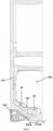
- FIG. 1 is a schematic front view of an embedded refrigerator according to an embodiment of the present disclosure.
- FIG. 2 is a schematic side sectional view of the embedded refrigerator shown in FIG. 1 .
- the refrigerator may generally include a refrigerator body 10, and the refrigerator body 10 includes a housing, a liner and other accessories.
- the housing is an outer structure of the refrigerator and protects the entire refrigerator.
- a heat insulating layer is additionally disposed between the housing and the liner of the refrigerator body 10, and the heat insulating layer is generally formed by a foaming process.
- the liner can be divided into one or more, and the liner can be divided into a refrigerating liner, a variable temperature liner, a freezing liner and the like according to the functions.
- the specific number and functions of liners can be configured according to the use requirements of the refrigerator.
- the liner at least includes a bottom liner 101, and the bottom liner 101 can generally be the freezing liner.
- the bottom liner 101 is the liner at the bottommost part of the refrigerator body 10, and defines a storage space 300 and a cooling chamber 100 located below the storage space 300.
- An evaporator 60 may be disposed in a middle front portion of the cooling chamber 100 slantingly upward from front to back along the depth direction of the refrigerator body.
- a bottom wall of the bottom liner 101 has a liner tilt portion, which is inclined upward from front to back, at a rear portion of the cooling chamber 100, and a tilt angle range is set to 30° to 40°, for example, the tilt angle can be set to be 33°, 35° or 38°, preferably 36.7°, thus providing a sufficient space for a compressor compartment 200.
- the storage space 300 can generally be used as a freezing space of the refrigerator.
- the embedded refrigerator includes a refrigerating system.
- the refrigerating system includes a throttling element (not shown in the figures), the evaporator 60, a refrigeration fan 40, a compressor 20 and a condenser 30 connected to the compressor 20. Since the circulation structure and working principle of the refrigerating system itself are well known to those skilled in the art and are easy to implement, in order not to conceal and obscure the improvements of the present application, the refrigerating system itself will not be described in detail below.
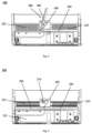
- the compressor compartment 200 is formed at a rear of a bottom of the refrigerator body 10 in the embodiment.
- the compressor compartment 200 is defined by a bottom wall 220, a back plate 240 disposed at a rear end of the bottom wall 220, side plates 230 disposed at both ends of the bottom wall 220, and a compressor compartment cover plate 210 disposed above the bottom wall 220.
- the compressor compartment 200 is internally at least equipped with the compressor 20, the condenser 30 and a heat dissipation fan 50.
- the compressor 20 and the condenser 30 are disposed in the compressor compartment 200 at an interval in a transverse direction of the refrigerator body 10.
- the condenser 30 can be a finned condenser, and fins of the condenser 30 are disposed from front to back along the depth direction of the refrigerator body 10, so that a heat dissipation air flow can pass through gaps between the fins directly, and the contact area with the heat dissipation air flow is therefore enlarged.
- the bottom wall 220 of the compressor compartment 200 is provided with an air flow suction inlet 2220 in front of the condenser 30, and an air flow exhaust outlet 2230 in front of the compressor 20.
- Grilles are respectively formed at the air flow suction inlet 2220 and the air flow exhaust outlet 2230, that is, the air flow suction inlet 2220 and the air flow exhaust outlet 2230 are communicated with an outside of the refrigerator body 10 by means of ventilation holes formed among the grilles, so that foreign matters (such as small animals) are prevented from entering the refrigerator body 10 through the air flow suction inlet 2220 and the air flow exhaust outlet 2230.
- the air outside the refrigerator body 10 can enter the compressor compartment 200 from the air flow suction inlet 2220, take away heat from the condenser 30 by exchanging heat with the condenser 30, then enter a side where the compressor 20 is positioned in the compressor compartment 200 through the heat dissipation fan 50 to take away heat generated by the operation of the compressor 20, and is then discharged outside from the air flow exhaust outlet 2230 so as to achieve the purpose of dissipating heat from equipment in the compressor compartment 200.
- the compressor compartment cover plate 210 of the embodiment includes an inclined front cover 211 and a top cover 212.
- the inclined front cover 211 is inclined upward from front to back in the depth direction of the refrigerator body 10 from front sides of the air flow suction inlet 2220 and the air flow exhaust outlet 2230.
- the top cover 212 extends horizontally rearward from a rear end of the inclined front cover 211 until being connected to the back plate 240. That is, the compressor compartment cover plate 210 is inclined to save an internal space of the refrigerator body 10 as much as possible and further increase the volume of the storage space 300 above the compressor compartment 200, thus improving the overall space utilization rate.
- the projection of the compressor compartment 200 on a horizontal plane is located behind the projection of the evaporator 60 on the horizontal plane, that is, the compressor compartment 200 and the evaporator 60 are placed in a staggered manner in a horizontal direction, which reduces the installation height of the evaporator 60 and increases the volume of the storage space 300.
- the refrigerator includes the heat dissipation fan 50.
- the heat dissipation fan 50 is disposed between the compressor 20 and the condenser 30 to facilitate the formation of a heat dissipation air flow that enters from the air flow suction inlet 2220 and flows through the condenser 30 for heat exchange, and is then discharged to the air flow exhaust outlet 2230 through the compressor 20.
- the heat dissipation fan 50 may be an axial flow fan, and its rotation axis is parallel to the transverse direction of the refrigerator body 10.
- An air inlet side of the heat dissipation fan 50 faces the condenser 30, and an air outlet side thereof faces the compressor 20, and the heat dissipation fan 50 is used to promote the formation of the heat dissipation air flow that enters from the air flow suction inlet 2220 and flows through the condenser 30 for heat exchange, and is then discharged to the air flow exhaust outlet 2230 through the compressor 20.
- a bracket and fan blades of the heat dissipation fan 50 can be assembled into an integral structure, and the outer periphery of the bracket of the fan is provided with an assembly structure to be directly fixed with a compartment wall of the compressor compartment 200. It is not necessary to set other brackets for fixing the fan in the compressor compartment 200, so that the structure in the compressor compartment 200 is simpler, the fixing effect is better, and the heat dissipation fan 50 operates more stably.
- an air shielding strip 280 is disposed on a lower surface of the refrigerator body 10.
- the air shielding strip 280 is disposed on the lower surface of the refrigerator body 10, and a middle portion of the air shielding strip 280 is a flexible section 283 that can be bent under a force, such that by bending the flexible section 283, the air shielding strip 280 is in an air shielding state in which the air shielding strip 280 divides a space between a lower part of the refrigerator body 10 and a ground supporting the refrigerator into an air inlet area communicated with the air flow suction inlet 2220 and an air outlet area communicated with the air flow exhaust outlet 2230.
- the flexible section 283 of the air shielding strip 280 can isolate the air flow suction inlet 2220 from the air flow exhaust outlet 2230 by bending, so as to prevent the heat dissipation air flow from circulating within a small range at the bottom of the refrigerator body 10, and further improve the heat dissipation efficiency.
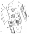
- the bottom wall 220 includes a compressor support plate 221, an air inlet plate 222, and an air outlet plate 223.
- the compressor support plate 221 is disposed at a rear portion of the bottom wall 220.
- the air inlet plate 222 extends forward from a front end of an area where the condenser 30 is located in the compressor support plate 221, and is provided with the air flow suction inlet 2220.
- the air outlet plate 223 extends forward from a front end of an area where the compressor 20 is located in the compressor support plate 221, and is provided with the air flow exhaust outlet 2230.
- the air shielding strip 280 extends linearly along a front end of the compressor support plate 221.
- the air shielding strip 280 has two states.
- the air shielding strip 280 is in the air shielding state (as shown in FIG. 4 ), and the air shielding strip 280 is bent to isolate the air flow suction inlet 2220 from the air flow exhaust outlet 2230, so as to avoid the circulation of the heat dissipation air flow in the small range at the bottom of the refrigerator body 10, and improve the heat dissipation efficiency; and during transportation, the air shielding strip 280 is in a received state (as shown in FIG. 5 ), and extends in a straight line along the front end of the compressor support plate 221, which is convenient to cooperate with a packaging box during transportation and handling, thus avoiding damage caused by collision.
- the air shielding strip 280 includes a first shielding section 281, the flexible section 283, and a second shielding section 282.
- the first shielding section 281 is fixed between the front end of the compressor support plate 221 and the air inlet plate 222.
- One end of the flexible section 283 is connected to one end of the first shielding section 281 located in a middle portion of the refrigerator body 10.
- the second shielding section 282 is connected to the other end of the flexible section 283 and disposed in an area in front of the compressor 20, and changes the extension direction according to a bending degree of the flexible section 283.
- the first shielding section 281 is always fixed on the lower surface of the refrigerator body 10, and the second shielding section 282 can rotate on the lower surface along with the bending of the flexible section 283 to separate the air flow suction inlet 2220 from the air flow exhaust outlet 2230, so as to avoid the circulation of the heat dissipation air flow in the small range at the bottom of the refrigerator body 10 and improve the heat dissipation efficiency.
- the second shielding section 282 is fixed between the front end of the compressor support plate 221 and the air outlet plate 223, and cooperates with the packaging box during transportation so as to avoid the damage caused by collision.
- the flexible section 283 is bent into an arc shape, and the second shielding section 282 extends obliquely forward from a position between the air inlet plate 222 and the air outlet plate 223 with an inclination direction from back to the front biased towards a side where the compressor 20 is positioned.
- the air outlet area is limited to the front side of the refrigerator body 10, so that the heat dissipation air flow can quickly leave the surrounding environment of the refrigerator, and the problem that the hotter heat dissipation air flow is scattered over an accommodation space of the embedded refrigerator after the heat exchange is completed, which causes the environment where the refrigerator is located to be hotter and increases the energy consumption of the refrigerator is therefore avoided.
- the air inlet area is restricted by the first shielding section 281 to be the other area around the refrigerator body 10 than the air outlet area.
- the air enters the compressor compartment 200 through the air flow suction inlet 2220 communicated with the air inlet area, fully exchanges heat with the condenser 30, then enters the side where the compressor 20 is positioned through the heat dissipation fan 50 to take away the heat generated by the operation of the compressor 20, enters the air outlet area from the air flow exhaust outlet 2230, and then leaves the bottom of the refrigerator body 10.
- a cross section of the air shielding strip 280 is L-shaped, where a horizontal side edge of the air shielding strip 280 is attached to the lower surface of the refrigerator body 10, a vertical side edge of the air shielding strip 280 is perpendicular to the lower surface of the refrigerator body 10, and the height of the vertical side edge matches the height from the lower surface of the refrigerator body 10 to the ground supporting the refrigerator, so as to fully separate the air flow suction inlet 2220 from the air flow exhaust outlet 2230; and therefore, the possibility that the heat dissipation air flow returns from the air flow exhaust outlet 2230 directly to the air inlet area through a gap between the air shielding strip 280 and the supporting ground is reduced, the circulation of the heat dissipation air flow within a small range at the bottom of the refrigerator body 10 is avoided, and the heat dissipation efficiency is improved.
- the refrigerator of the embodiment further includes a partition 270.
- the partition 270 is disposed upward between the air inlet plate 222 and the air outlet plate 223 to separate an area in front of the compressor 20 and an area in front of the condenser 30 in the compressor compartment 200.
- the partition 270 includes a bottom plate 276, a first side plate 271 and a second side plate 272.
- the bottom plate 276 is positioned between the air inlet plate 222 and the air outlet plate 223.
- the first side plate 271 extends upward from an end, close to the air outlet plate 223, of the bottom plate 276 to isolate the area in front of the compressor 20.
- the second side plate 272 extends upward from an end, close to the air inlet plate 222, of the bottom plate 276 to isolate the area in front of the condenser 30.
- the partition 270 isolates the air flow suction inlet 2220 from the air flow exhaust outlet 2230, so that the heat dissipation air flow can only be discharged from the air flow exhaust outlet 2230 through the air flow suction inlet 2220, the condenser 30, the heat dissipation fan 50 and the compressor 20, which makes the heat dissipation more sufficient.
- a lower surface of the bottom plate 276 is provided with a claw 275 for fixing the second shielding section 282, so as to limit the position of the second shielding section 282 when the air shielding strip 280 is in the air shielding state.
- a limit slot 274 adapted to the shape of a front end of the heat dissipation fan 50 is formed in a rear end wall of the first side plate 271 for accommodating a front portion of the heat dissipation fan 50.
- the compressor compartment 200 is divided into a compressor side and a condenser side by the heat dissipation fan 50 and the partition 270. After fully exchanging heat with the condenser 30, the heat dissipation air flow can enter the compressor 20 side through the heat dissipation fan 50, and can be discharged out of the refrigerator body 10 from the air flow exhaust outlet 2230 only after taking away the heat generated during the operation of the compressor 20.
- a drain pipe 110 of the embedded refrigerator extends from a drain outlet at a bottom of the liner above the compressor compartment cover plate 210 to an evaporating dish 250 through an area between the first side plate 271 and the second side plate 272.
- the arrangement of a reserved opening between the first side plate 271 and the second side plate 272 can effectively save an internal space of the compressor compartment 200, and further make an internal structure of the refrigerator body 10 more compact, thus increasing the overall space utilization rate of the refrigerator.
- the embedded refrigerator of the embodiment is provided with an air deflector 273.
- the air deflector 273 extends from the first side plate 271 to a front of the compressor 20 to allow the heat dissipation air flow flowing through the compressor 20 to flow from a side away from the first side plate 271 to the air flow exhaust outlet 2230, and a projection of a tail end of the air deflector 273 in the depth direction of the refrigerator body 10 is aligned with a middle portion of the compressor 20.
- a starting point of the air deflector 273 is disposed at a position where the heat dissipation fan 50 is located, so as to prevent the diffusion of heat dissipation; and the end point thereof is aligned with the middle portion of the compressor 20, which can guide all the heat dissipation air flow to the whole surface of the compressor 20 to maximize the heat dissipation of the compressor 20, thus preventing the air volume loss when the heat dissipation air flow moves from an initial point to an apex , and further effectively lowering the temperature of the compressor 20.
- the air volume swirl is reduced, the temperature of the condenser 30 is lowered, and effective energy conservation is achieved.
- the condenser 30 is cuboid in an overall shape, and is installed to allow its radiating fins to extend along the depth direction of the refrigerator body 10, so that the air entering from the air flow suction inlet 2220 flows along passages between the radiating fins for heat exchange, and then flows to the heat dissipation fan 50 from an interval between the condenser 30 and the back plate 240.
- the radiating fins are in parallel arrangement along the depth direction. After entering from the air flow suction inlet 2220, the air can smoothly contact and exchange heat with all the fins through gaps between the radiating fins, thus greatly enhancing the heat dissipation effect.
- the condenser 30 can be tilted upward from front to back along the depth direction of the refrigerator body 10, which can effectively utilize the air inhaled in the air flow suction inlet 2220 to increase the full contact area between the air and the condenser 30 and enhance the heat dissipation effect.
- the condenser 30 may also use a micro-channel heat exchanger.
- an air guide assembly 290 can also be disposed in the compressor compartment 200.
- the air guide assembly 290 is disposed at an outer periphery of the condenser 30, and is configured to guide the air inhaled from the air flow suction inlet 2220 to completely cross the condenser 30, so as to avoid the air flow escaping from the outer periphery of the condenser 30, and allow the air flow to flow to the heat dissipation fan 50 only from the interval between the condenser 30 and the back plate 240.
- the heat dissipation air flow can be enabled to fully contact the condenser 30, so that the heat dissipation performance is improved.
- the air shielding strip 280 is disposed on the lower surface of the refrigerator body 10, the air shielding strip 280 has the flexible section 283, and the air flow suction inlet 2220 can be isolated from the air flow exhaust outlet 2230 by bending the flexible section 283, so that the circulation of the heat dissipation air flow within the small range at the bottom of the refrigerator body 10 is avoided, and the heat dissipation efficiency is increased.
- the air shielding strip 280 extends linearly along the front end of the compressor support plate 221 when the flexible section 283 is not bent, which is convenient to cooperate with the packaging box during transportation, thus reducing the risk of collision damage.
Landscapes
- Engineering & Computer Science (AREA)
- Chemical & Material Sciences (AREA)
- Combustion & Propulsion (AREA)
- Physics & Mathematics (AREA)
- Mechanical Engineering (AREA)
- Thermal Sciences (AREA)
- General Engineering & Computer Science (AREA)
- Devices That Are Associated With Refrigeration Equipment (AREA)
Claims (7)
- Eingebauter Kühlschrank umfassend:ein Kühlsystem, das einen Kompressor (20) und einen Kondensator (30) umfasst, der an den Kompressor (20) angeschlossen ist;einen Kühlschrankkörper (10), wobei ein Kompressorraum (200) an einer Rückseite eines Bodens des Kühlschrankkörpers versehen ist, wobei der Kompressor (20) und der Kondensator (30) im Kompressorraum (200) im Abstand in der Querrichtung des Kühlschrankkörpers versehen sind, wobei eine Bodenwand des Kompressorraums (200) mit einem Luftstrom-Saugeinlass (2220) vor dem Kondensator (30) und mit einem Luftstrom-Abgasauslass (2230) vor dem Kompressor versehen ist, und wobei die Bodenwand des Kompressorraums (200) eine Kompressorträgerplatte (221) umfasst, die an einem hinteren Abschnitt der Bodenwand angeordnet ist;einen Wärmeableitungslüfter, der zwischen dem Kompressor (20) und dem Kondensator angeordnet ist, um die Bildung eines Wärmeableitungsluftstroms zu erleichtern, der vom Luftstrom-Saugeinlass (2220) eintritt und zum Wärmeaustausch durch den Kondensator (30) fließt und dann durch den Kompressor zum Luftstrom-Abgasauslass (2230) abgeleitet wird; undeinen Luftschirmstreifen (280), der auf einer Unterfläche des Kühlschrankkörpers (10) angeordnet ist, wobei der Luftschirmstreifen (280) einen Luftschirmzustand und einen Empfangszustand aufweist,wobei ein Mittelteil des Luftschirmstreifens (280) ein flexibler Abschnitt (283) ist, der unter einer Kraft verbiegen werden kann, so dass der Luftschirmstreifen (280) durch Biegen des flexiblen Abschnitts (283) im Luftschirmzustand ist und im Empfangszustand ist, wenn der flexible Abschnitt (283) nicht verbiegen ist, wobeiim Luftschirmzustand der Luftschirmstreifen (280) einen Raum zwischen einem unteren Teil des Kühlschrankkörpers (10) und einem Boden, der den Kühlschrank trägt, in einen Lufteinlassbereich, der mit dem Luftstrom-Saugeinlass (2220) kommuniziert, und einen Luftauslassbereich unterteilt, der mit dem Luftstrom-Abgasauslass (2230) kommuniziert; undwobei im Empfangszustand sich der Luftschirmstreifen (280) linear entlang eines Vorderenden der Kompressorträgerplatte (221) erstreckt, dadurch gekennzeichnet, dass die Bodenwand des Kompressorraums (200) ferner umfasst:eine Lufteinlassplatte (222), die sich von einem vorderen Ende eines Bereichs nach vorne erstreckt, in dem sich der Kondensator (30) in der Kompressorträgerplatte (221) befindet, wobei der Luftstrom-Saugeinlass (2220) in der Lufteinlassplatte (222) gebildet wird; undeine Luftauslassplatte (223), die sich von einem vorderen Ende eines Bereichs nach vorne erstreckt, in dem sich der Kompressor (20) in der Kompressorträgerplatte (221) befindet, wobei der Luftstrom-Abgassauslass (2230) in der Luftauslassplatte (223) gebildet wird, wobei der Luftschirmstreifen (280) umfasst:einen ersten Abschirmabschnitt (281), der zwischen dem Vorderenden der Kompressorträgerplatte (221) und der Lufteinlassplatte (222) befestigt ist;den flexiblen Abschnitt (283), dessen eines Ende mit einem in einem Mittelteil des Kühlschrankkörpers angeordneten Ende des ersten Abschirmabschnitts (281) verbunden ist; undeinen zweiten Abschirmabschnitt (282), der mit dem anderen Ende des flexiblen Abschnitts (283) verbunden ist, in einem Bereich vor dem Kompressor versehen ist und eine Ausdehnungsrichtung entsprechend dem Biegegrad des flexiblen Abschnitts (283) ändert,wobeider flexible Abschnitt (283) in eine Bogenform gebogen ist, und der zweite Abschirmabschnitt (282) sich schräg nach vorne von einer Position zwischen der Lufteinlassplatte (222) und der Luftauslassplatte (223) mit einer Neigungsrichtung von hinten nach vorne erstreckt, die zu einer Seite hin geneigt ist, wo der Kompressor (20) positioniert ist, wenn sich der Luftschirmstreifen (280) im Luftschirmzustand befindet.
- Eingebauter Kühlschrank gemäß Anspruch 1, ferner umfassend:
eine Trennwand, die zwischen der Lufteinlassplatte (222) und der Luftauslassplatte (223) versehen ist und verwendet wird, um einen Bereich vor dem Kompressor (20) und einen Bereich vor dem Kondensator (30) im Kompressorraum (200) zu trennen und Folgende umfasst:eine Bodenplatte, die zwischen der Lufteinlassplatte (222) und der Luftauslassplatte (223) positioniert ist;eine erste Seitenplatte, die sich von einem Ende der Bodenplatte in der Nähe der Luftauslassplatte (223) nach oben erstreckt, um den Bereich vor dem Kompressor zu isolieren; undeine zweite Seitenplatte, die sich von einem Ende der Bodenplatte in der Nähe der Lufteinlassplatte (222) nach oben erstreckt, um den Bereich vor dem Kondensator (30) zu isolieren, wobeieine Unterfläche der Bodenplatte mit einer Klaue zum Fixieren des zweiten Abschirmabschnitts (282) versehen ist, um die Position des zweiten Abschirmabschnitts (282) zu begrenzen, wenn sich der Luftschirmstreifen (280) im Luftschirmzustand befindet. - Eingebauter Kühlschrank gemäß Anspruch 2, wobeiwobei in einer hinteren Endwand der ersten Seitenplatte ein an die Form eines vorderen Endes des Wärmeableitungslüfters angepasster Begrenzungsschlitz zur Aufnahme eines vorderen Abschnitts des Wärmeableitungslüfters ausgebildet ist, undder Wärmeableitungslüfter sich von einem hinteren Abschnitt der ersten Seitenplatte bis zu einer Position zwischen dem Kompressor (20) und dem Kondensator (30) erstreckt.
- Eingebauter Kühlschrank gemäß Anspruch 2 oder 3, ferner umfassend:
einen Luftableiter, der sich von der ersten Seitenplatte bis zur Vorderseite des Kompressors erstreckt, um den durch den Kompressor fließenden Wärmeableitluftstrom von einer Seite entfernt von der ersten Seitenplatte zum Luftstrom-Abgasauslass zu ermöglichen, wobei eine Projizierung eines Endends des Luftableiters in Tiefenrichtung des Kühlschrankkörpers (10) mit einem Mittelteil des Kompressors ausgerichtet ist. - Eingebauter Kühlschrank gemäß einem der Ansprüche 1 bis 4, wobei
ein Querschnitt des Luftschirmstreifens (280) L-förmig ist, wobei eine horizontale Seitenkante des Luftschirmstreifens (280) an der Unterfläche des Kühlschrankkörpers befestigt ist, eine vertikale Seitenkante des Luftschirmstreifens (280) senkrecht zur Unterfläche des Kühlschrankkörpers ist und die Höhe der vertikalen Seitenkante mit der Höhe von der Unterfläche des Kühlschrankkörpers (10) bis zum Boden entspricht, der den Kühlschrank trägt. - Eingebauter Kühlschrank gemäß einem der Ansprüche 1 bis 5, wobei
Gitter jeweils am Luftstrom-Saugeinlass (2220) und am Luftstrom-Abgasauslass (2230) ausgebildet sind, um zu verhindern, dass Fremdstoffe in den Kühlschrankkörper gelangen. - Eingebauter Kühlschrank gemäß einem der Ansprüche 1 bis 6, wobei
der Kondensator (30) eine quaderförmige Gesamtgestalt aufweist und so installiert ist, dass seine Kühlrippen entlang der Tiefenrichtung des Kühlschrankkörpers ausdehnen können, so dass die Luft, die aus dem Luftstrom-Saugeinlass (2220) eintritt, durch Durchgänge zwischen den Kühlrippen in den Kompressor (20) fließt.
Applications Claiming Priority (2)
| Application Number | Priority Date | Filing Date | Title |
|---|---|---|---|
| CN202010833852.4A CN114076462B (zh) | 2020-08-18 | 2020-08-18 | 嵌入式冰箱 |
| PCT/CN2021/109163 WO2022037382A1 (zh) | 2020-08-18 | 2021-07-29 | 嵌入式冰箱 |
Publications (3)
| Publication Number | Publication Date |
|---|---|
| EP4174414A1 EP4174414A1 (de) | 2023-05-03 |
| EP4174414A4 EP4174414A4 (de) | 2023-12-20 |
| EP4174414B1 true EP4174414B1 (de) | 2025-04-02 |
Family
ID=80281363
Family Applications (1)
| Application Number | Title | Priority Date | Filing Date |
|---|---|---|---|
| EP21857477.0A Active EP4174414B1 (de) | 2020-08-18 | 2021-07-29 | Eingebetteter kühlschrank |
Country Status (3)
| Country | Link |
|---|---|
| EP (1) | EP4174414B1 (de) |
| CN (1) | CN114076462B (de) |
| WO (1) | WO2022037382A1 (de) |
Families Citing this family (1)
| Publication number | Priority date | Publication date | Assignee | Title |
|---|---|---|---|---|
| CN117346430A (zh) * | 2022-06-29 | 2024-01-05 | 青岛海尔电冰箱有限公司 | 冰箱 |
Citations (6)
| Publication number | Priority date | Publication date | Assignee | Title |
|---|---|---|---|---|
| JPH10334327A (ja) * | 1997-05-29 | 1998-12-18 | Fuji Electric Co Ltd | 自動販売機 |
| KR20060120752A (ko) * | 2005-05-23 | 2006-11-28 | 엘지전자 주식회사 | 스크롤덕트가 구비된 냉장고 |
| WO2009141117A1 (en) * | 2008-05-23 | 2009-11-26 | Aktiebolaget Electrolux | Cold appliance |
| EP3447414A1 (de) * | 2017-08-21 | 2019-02-27 | Liebherr-Hausgeräte Ochsenhausen GmbH | Kühl- und/oder gefriergerät |
| CN208688080U (zh) * | 2018-04-13 | 2019-04-02 | 青岛海尔股份有限公司 | 冰箱 |
| CN210036003U (zh) * | 2019-04-26 | 2020-02-07 | 青岛海尔特种电冰箱有限公司 | 蒸发器与接水盘相匹配的冰箱 |
Family Cites Families (17)
| Publication number | Priority date | Publication date | Assignee | Title |
|---|---|---|---|---|
| US5881567A (en) * | 1997-09-29 | 1999-03-16 | Whirlpool Corporation | Refrigerator condenser air flow |
| DE19746962A1 (de) * | 1997-10-24 | 1999-04-29 | Aeg Hausgeraete Gmbh | Kühl- und/oder Gefriergerät mit einem ersten Kanal zur Heranführung von Umgebungsluft und einem zweiten Kanal zur Abfuhr der herangeführten Umgebungsluft |
| US6776000B2 (en) * | 2002-07-02 | 2004-08-17 | Lg Electronics Inc. | Built-in refrigerator |
| KR20100062019A (ko) * | 2008-12-01 | 2010-06-10 | 엘지전자 주식회사 | 냉장고 |
| EP2638340B1 (de) * | 2010-11-11 | 2015-09-09 | Arçelik Anonim Sirketi | Kühlschrank mit gekühltem maschinenraum |
| CN202511546U (zh) * | 2011-03-11 | 2012-10-31 | 泰州乐金电子冷机有限公司 | 一种冰箱 |
| JP2012202567A (ja) * | 2011-03-24 | 2012-10-22 | Mitsubishi Electric Corp | 冷蔵庫 |
| EP2743618B1 (de) * | 2012-12-17 | 2016-03-02 | Electrolux Home Products Corporation N.V. | Kühlschrank für Lebensmittel |
| CN108413686B (zh) * | 2018-02-06 | 2020-09-29 | 青岛海尔股份有限公司 | 冰箱 |
| CN208817833U (zh) * | 2018-04-13 | 2019-05-03 | 青岛海尔股份有限公司 | 从底部进行散热的冰箱 |
| CN110375506B (zh) * | 2018-04-13 | 2024-01-12 | 海尔智家股份有限公司 | 从底部进行散热的冰箱 |
| CN110375507B (zh) * | 2018-04-13 | 2024-01-12 | 海尔智家股份有限公司 | 从底部进行散热的冰箱 |
| CN208817832U (zh) * | 2018-04-13 | 2019-05-03 | 青岛海尔股份有限公司 | 从底部进行散热的冰箱 |
| CN208817830U (zh) * | 2018-04-13 | 2019-05-03 | 青岛海尔股份有限公司 | 冰箱 |
| CN110375482B (zh) * | 2018-04-13 | 2024-01-12 | 海尔智家股份有限公司 | 从底部进行散热的冰箱 |
| CN110375508B (zh) * | 2018-04-13 | 2024-03-22 | 海尔智家股份有限公司 | 从底部进行散热的冰箱 |
| CN209893736U (zh) * | 2019-02-26 | 2020-01-03 | 青岛海尔电冰箱有限公司 | 托板上开设底进风口和底出风口的冰箱 |
-
2020
- 2020-08-18 CN CN202010833852.4A patent/CN114076462B/zh active Active
-
2021
- 2021-07-29 EP EP21857477.0A patent/EP4174414B1/de active Active
- 2021-07-29 WO PCT/CN2021/109163 patent/WO2022037382A1/zh not_active Ceased
Patent Citations (6)
| Publication number | Priority date | Publication date | Assignee | Title |
|---|---|---|---|---|
| JPH10334327A (ja) * | 1997-05-29 | 1998-12-18 | Fuji Electric Co Ltd | 自動販売機 |
| KR20060120752A (ko) * | 2005-05-23 | 2006-11-28 | 엘지전자 주식회사 | 스크롤덕트가 구비된 냉장고 |
| WO2009141117A1 (en) * | 2008-05-23 | 2009-11-26 | Aktiebolaget Electrolux | Cold appliance |
| EP3447414A1 (de) * | 2017-08-21 | 2019-02-27 | Liebherr-Hausgeräte Ochsenhausen GmbH | Kühl- und/oder gefriergerät |
| CN208688080U (zh) * | 2018-04-13 | 2019-04-02 | 青岛海尔股份有限公司 | 冰箱 |
| CN210036003U (zh) * | 2019-04-26 | 2020-02-07 | 青岛海尔特种电冰箱有限公司 | 蒸发器与接水盘相匹配的冰箱 |
Also Published As
| Publication number | Publication date |
|---|---|
| CN114076462B (zh) | 2022-12-16 |
| EP4174414A1 (de) | 2023-05-03 |
| EP4174414A4 (de) | 2023-12-20 |
| CN114076462A (zh) | 2022-02-22 |
| WO2022037382A1 (zh) | 2022-02-24 |
Similar Documents
| Publication | Publication Date | Title |
|---|---|---|
| EP3929510B1 (de) | Kühlschrank | |
| EP3929509B1 (de) | Kühlschrank mit einer trennwand im maschinenraum | |
| CN216716636U (zh) | 蒸发器、风道组件及制冷设备 | |
| CN216716718U (zh) | 风道组件及制冷设备 | |
| CN216716716U (zh) | 风道组件及制冷设备 | |
| CN216716717U (zh) | 风道组件及制冷设备 | |
| EP4174414B1 (de) | Eingebetteter kühlschrank | |
| US6155065A (en) | Evaporator coil support for a room air conditioner | |
| WO2022037719A1 (zh) | 将冷凝器布置于压机舱内的冰箱 | |
| CN114076455B (zh) | 一种嵌入式冰箱 | |
| WO2024002087A1 (zh) | 冰箱 | |
| AU2020227335A1 (en) | Refrigerator having air blower located upstream of transverse side of evaporator | |
| CN214039109U (zh) | 嵌入式冰箱 | |
| WO2022037717A1 (zh) | 压机舱内形成散热气流通道的冰箱 | |
| WO2022037718A1 (zh) | 将冷凝器布置于压机舱内的冰箱 | |
| CN115479330A (zh) | 一种电控盒及空调器 | |
| CN110375475B (zh) | 优化蒸发器安装结构的冰箱 | |
| CN217058121U (zh) | 风道组件及制冷设备 | |
| CN116412608B (zh) | 风道组件及制冷设备 | |
| EP3926266B1 (de) | Kühlschrank mit einem quer neben und stromabwärts des verdampfers angeordneten gebläse | |
| JP3726756B2 (ja) | 冷蔵庫 | |
| CN116412593B (zh) | 制冷设备 | |
| CN222012136U (zh) | 空调室外机 | |
| CN222364013U (zh) | 一体式空调器 | |
| JP3211551B2 (ja) | 冷凍冷蔵庫 |
Legal Events
| Date | Code | Title | Description |
|---|---|---|---|
| STAA | Information on the status of an ep patent application or granted ep patent |
Free format text: STATUS: THE INTERNATIONAL PUBLICATION HAS BEEN MADE |
|
| PUAI | Public reference made under article 153(3) epc to a published international application that has entered the european phase |
Free format text: ORIGINAL CODE: 0009012 |
|
| STAA | Information on the status of an ep patent application or granted ep patent |
Free format text: STATUS: REQUEST FOR EXAMINATION WAS MADE |
|
| 17P | Request for examination filed |
Effective date: 20230126 |
|
| AK | Designated contracting states |
Kind code of ref document: A1 Designated state(s): AL AT BE BG CH CY CZ DE DK EE ES FI FR GB GR HR HU IE IS IT LI LT LU LV MC MK MT NL NO PL PT RO RS SE SI SK SM TR |
|
| DAV | Request for validation of the european patent (deleted) | ||
| DAX | Request for extension of the european patent (deleted) | ||
| STAA | Information on the status of an ep patent application or granted ep patent |
Free format text: STATUS: EXAMINATION IS IN PROGRESS |
|
| A4 | Supplementary search report drawn up and despatched |
Effective date: 20231120 |
|
| RIC1 | Information provided on ipc code assigned before grant |
Ipc: F25D 23/10 20060101ALI20231114BHEP Ipc: F25D 11/02 20060101ALI20231114BHEP Ipc: F25D 23/00 20060101AFI20231114BHEP |
|
| 17Q | First examination report despatched |
Effective date: 20231201 |
|
| GRAP | Despatch of communication of intention to grant a patent |
Free format text: ORIGINAL CODE: EPIDOSNIGR1 |
|
| STAA | Information on the status of an ep patent application or granted ep patent |
Free format text: STATUS: GRANT OF PATENT IS INTENDED |
|
| INTG | Intention to grant announced |
Effective date: 20241212 |
|
| GRAS | Grant fee paid |
Free format text: ORIGINAL CODE: EPIDOSNIGR3 |
|
| GRAA | (expected) grant |
Free format text: ORIGINAL CODE: 0009210 |
|
| STAA | Information on the status of an ep patent application or granted ep patent |
Free format text: STATUS: THE PATENT HAS BEEN GRANTED |
|
| AK | Designated contracting states |
Kind code of ref document: B1 Designated state(s): AL AT BE BG CH CY CZ DE DK EE ES FI FR GB GR HR HU IE IS IT LI LT LU LV MC MK MT NL NO PL PT RO RS SE SI SK SM TR |
|
| REG | Reference to a national code |
Ref country code: GB Ref legal event code: FG4D |
|
| REG | Reference to a national code |
Ref country code: CH Ref legal event code: EP |
|
| REG | Reference to a national code |
Ref country code: IE Ref legal event code: FG4D |
|
| REG | Reference to a national code |
Ref country code: DE Ref legal event code: R096 Ref document number: 602021028674 Country of ref document: DE |
|
| REG | Reference to a national code |
Ref country code: NL Ref legal event code: MP Effective date: 20250402 |
|
| PG25 | Lapsed in a contracting state [announced via postgrant information from national office to epo] |
Ref country code: NL Free format text: LAPSE BECAUSE OF FAILURE TO SUBMIT A TRANSLATION OF THE DESCRIPTION OR TO PAY THE FEE WITHIN THE PRESCRIBED TIME-LIMIT Effective date: 20250402 |
|
| REG | Reference to a national code |
Ref country code: AT Ref legal event code: MK05 Ref document number: 1781618 Country of ref document: AT Kind code of ref document: T Effective date: 20250402 |
|
| PG25 | Lapsed in a contracting state [announced via postgrant information from national office to epo] |
Ref country code: ES Free format text: LAPSE BECAUSE OF FAILURE TO SUBMIT A TRANSLATION OF THE DESCRIPTION OR TO PAY THE FEE WITHIN THE PRESCRIBED TIME-LIMIT Effective date: 20250402 Ref country code: PT Free format text: LAPSE BECAUSE OF FAILURE TO SUBMIT A TRANSLATION OF THE DESCRIPTION OR TO PAY THE FEE WITHIN THE PRESCRIBED TIME-LIMIT Effective date: 20250804 Ref country code: FI Free format text: LAPSE BECAUSE OF FAILURE TO SUBMIT A TRANSLATION OF THE DESCRIPTION OR TO PAY THE FEE WITHIN THE PRESCRIBED TIME-LIMIT Effective date: 20250402 |
|
| PGFP | Annual fee paid to national office [announced via postgrant information from national office to epo] |
Ref country code: DE Payment date: 20250711 Year of fee payment: 5 |
|
| REG | Reference to a national code |
Ref country code: LT Ref legal event code: MG9D |
|
| PG25 | Lapsed in a contracting state [announced via postgrant information from national office to epo] |
Ref country code: GR Free format text: LAPSE BECAUSE OF FAILURE TO SUBMIT A TRANSLATION OF THE DESCRIPTION OR TO PAY THE FEE WITHIN THE PRESCRIBED TIME-LIMIT Effective date: 20250703 Ref country code: NO Free format text: LAPSE BECAUSE OF FAILURE TO SUBMIT A TRANSLATION OF THE DESCRIPTION OR TO PAY THE FEE WITHIN THE PRESCRIBED TIME-LIMIT Effective date: 20250702 |
|
| PG25 | Lapsed in a contracting state [announced via postgrant information from national office to epo] |
Ref country code: PL Free format text: LAPSE BECAUSE OF FAILURE TO SUBMIT A TRANSLATION OF THE DESCRIPTION OR TO PAY THE FEE WITHIN THE PRESCRIBED TIME-LIMIT Effective date: 20250402 |
|
| PG25 | Lapsed in a contracting state [announced via postgrant information from national office to epo] |
Ref country code: BG Free format text: LAPSE BECAUSE OF FAILURE TO SUBMIT A TRANSLATION OF THE DESCRIPTION OR TO PAY THE FEE WITHIN THE PRESCRIBED TIME-LIMIT Effective date: 20250402 |
|
| PG25 | Lapsed in a contracting state [announced via postgrant information from national office to epo] |
Ref country code: HR Free format text: LAPSE BECAUSE OF FAILURE TO SUBMIT A TRANSLATION OF THE DESCRIPTION OR TO PAY THE FEE WITHIN THE PRESCRIBED TIME-LIMIT Effective date: 20250402 |
|
| PG25 | Lapsed in a contracting state [announced via postgrant information from national office to epo] |
Ref country code: AT Free format text: LAPSE BECAUSE OF FAILURE TO SUBMIT A TRANSLATION OF THE DESCRIPTION OR TO PAY THE FEE WITHIN THE PRESCRIBED TIME-LIMIT Effective date: 20250402 |
|
| PG25 | Lapsed in a contracting state [announced via postgrant information from national office to epo] |
Ref country code: RS Free format text: LAPSE BECAUSE OF FAILURE TO SUBMIT A TRANSLATION OF THE DESCRIPTION OR TO PAY THE FEE WITHIN THE PRESCRIBED TIME-LIMIT Effective date: 20250702 |
|
| PG25 | Lapsed in a contracting state [announced via postgrant information from national office to epo] |
Ref country code: IS Free format text: LAPSE BECAUSE OF FAILURE TO SUBMIT A TRANSLATION OF THE DESCRIPTION OR TO PAY THE FEE WITHIN THE PRESCRIBED TIME-LIMIT Effective date: 20250802 |
|
| PG25 | Lapsed in a contracting state [announced via postgrant information from national office to epo] |
Ref country code: LV Free format text: LAPSE BECAUSE OF FAILURE TO SUBMIT A TRANSLATION OF THE DESCRIPTION OR TO PAY THE FEE WITHIN THE PRESCRIBED TIME-LIMIT Effective date: 20250402 |
|
| REG | Reference to a national code |
Ref country code: DE Ref legal event code: R097 Ref document number: 602021028674 Country of ref document: DE |
|
| PG25 | Lapsed in a contracting state [announced via postgrant information from national office to epo] |
Ref country code: SM Free format text: LAPSE BECAUSE OF FAILURE TO SUBMIT A TRANSLATION OF THE DESCRIPTION OR TO PAY THE FEE WITHIN THE PRESCRIBED TIME-LIMIT Effective date: 20250402 Ref country code: DK Free format text: LAPSE BECAUSE OF FAILURE TO SUBMIT A TRANSLATION OF THE DESCRIPTION OR TO PAY THE FEE WITHIN THE PRESCRIBED TIME-LIMIT Effective date: 20250402 |
|
| PG25 | Lapsed in a contracting state [announced via postgrant information from national office to epo] |
Ref country code: CZ Free format text: LAPSE BECAUSE OF FAILURE TO SUBMIT A TRANSLATION OF THE DESCRIPTION OR TO PAY THE FEE WITHIN THE PRESCRIBED TIME-LIMIT Effective date: 20250402 |
|
| PG25 | Lapsed in a contracting state [announced via postgrant information from national office to epo] |
Ref country code: EE Free format text: LAPSE BECAUSE OF FAILURE TO SUBMIT A TRANSLATION OF THE DESCRIPTION OR TO PAY THE FEE WITHIN THE PRESCRIBED TIME-LIMIT Effective date: 20250402 |
|
| PG25 | Lapsed in a contracting state [announced via postgrant information from national office to epo] |
Ref country code: SK Free format text: LAPSE BECAUSE OF FAILURE TO SUBMIT A TRANSLATION OF THE DESCRIPTION OR TO PAY THE FEE WITHIN THE PRESCRIBED TIME-LIMIT Effective date: 20250402 |
|
| PG25 | Lapsed in a contracting state [announced via postgrant information from national office to epo] |
Ref country code: IT Free format text: LAPSE BECAUSE OF FAILURE TO SUBMIT A TRANSLATION OF THE DESCRIPTION OR TO PAY THE FEE WITHIN THE PRESCRIBED TIME-LIMIT Effective date: 20250402 |
|
| PLBE | No opposition filed within time limit |
Free format text: ORIGINAL CODE: 0009261 |
|
| STAA | Information on the status of an ep patent application or granted ep patent |
Free format text: STATUS: NO OPPOSITION FILED WITHIN TIME LIMIT |
|
| REG | Reference to a national code |
Ref country code: CH Ref legal event code: L10 Free format text: ST27 STATUS EVENT CODE: U-0-0-L10-L00 (AS PROVIDED BY THE NATIONAL OFFICE) Effective date: 20260211 |
|
| REG | Reference to a national code |
Ref country code: CH Ref legal event code: H13 Free format text: ST27 STATUS EVENT CODE: U-0-0-H10-H13 (AS PROVIDED BY THE NATIONAL OFFICE) Effective date: 20260224 |
|
| PG25 | Lapsed in a contracting state [announced via postgrant information from national office to epo] |
Ref country code: RO Free format text: LAPSE BECAUSE OF FAILURE TO SUBMIT A TRANSLATION OF THE DESCRIPTION OR TO PAY THE FEE WITHIN THE PRESCRIBED TIME-LIMIT Effective date: 20250402 |
|
| 26N | No opposition filed |
Effective date: 20260105 |
|
| PG25 | Lapsed in a contracting state [announced via postgrant information from national office to epo] |
Ref country code: LU Free format text: LAPSE BECAUSE OF NON-PAYMENT OF DUE FEES Effective date: 20250729 |
|
| GBPC | Gb: european patent ceased through non-payment of renewal fee |
Effective date: 20250729 |
|
| REG | Reference to a national code |
Ref country code: BE Ref legal event code: MM Effective date: 20250731 |
|
| PG25 | Lapsed in a contracting state [announced via postgrant information from national office to epo] |
Ref country code: GB Free format text: LAPSE BECAUSE OF NON-PAYMENT OF DUE FEES Effective date: 20250729 |
|
| PG25 | Lapsed in a contracting state [announced via postgrant information from national office to epo] |
Ref country code: BE Free format text: LAPSE BECAUSE OF NON-PAYMENT OF DUE FEES Effective date: 20250731 |
|
| PG25 | Lapsed in a contracting state [announced via postgrant information from national office to epo] |
Ref country code: FR Free format text: LAPSE BECAUSE OF NON-PAYMENT OF DUE FEES Effective date: 20250731 |