EP4174339B1 - Scheibenbremse, bremsbelag und bremssystem, das diese scheibenbremse und bremsbeläge umfasst - Google Patents
Scheibenbremse, bremsbelag und bremssystem, das diese scheibenbremse und bremsbeläge umfasst Download PDFInfo
- Publication number
- EP4174339B1 EP4174339B1 EP21204888.8A EP21204888A EP4174339B1 EP 4174339 B1 EP4174339 B1 EP 4174339B1 EP 21204888 A EP21204888 A EP 21204888A EP 4174339 B1 EP4174339 B1 EP 4174339B1
- Authority
- EP
- European Patent Office
- Prior art keywords
- brake
- disc
- channels
- caliper
- lining
- Prior art date
- Legal status (The legal status is an assumption and is not a legal conclusion. Google has not performed a legal analysis and makes no representation as to the accuracy of the status listed.)
- Active
Links
Images

Classifications
-
- F—MECHANICAL ENGINEERING; LIGHTING; HEATING; WEAPONS; BLASTING
- F16—ENGINEERING ELEMENTS AND UNITS; GENERAL MEASURES FOR PRODUCING AND MAINTAINING EFFECTIVE FUNCTIONING OF MACHINES OR INSTALLATIONS; THERMAL INSULATION IN GENERAL
- F16D—COUPLINGS FOR TRANSMITTING ROTATION; CLUTCHES; BRAKES
- F16D65/00—Parts or details
- F16D65/0031—Devices for retaining friction material debris, e.g. dust collectors or filters
-
- F—MECHANICAL ENGINEERING; LIGHTING; HEATING; WEAPONS; BLASTING
- F16—ENGINEERING ELEMENTS AND UNITS; GENERAL MEASURES FOR PRODUCING AND MAINTAINING EFFECTIVE FUNCTIONING OF MACHINES OR INSTALLATIONS; THERMAL INSULATION IN GENERAL
- F16D—COUPLINGS FOR TRANSMITTING ROTATION; CLUTCHES; BRAKES
- F16D55/00—Brakes with substantially-radial braking surfaces pressed together in axial direction, e.g. disc brakes
- F16D55/02—Brakes with substantially-radial braking surfaces pressed together in axial direction, e.g. disc brakes with axially-movable discs or pads pressed against axially-located rotating members
- F16D55/22—Brakes with substantially-radial braking surfaces pressed together in axial direction, e.g. disc brakes with axially-movable discs or pads pressed against axially-located rotating members by clamping an axially-located rotating disc between movable braking members, e.g. movable brake discs or brake pads
- F16D55/224—Brakes with substantially-radial braking surfaces pressed together in axial direction, e.g. disc brakes with axially-movable discs or pads pressed against axially-located rotating members by clamping an axially-located rotating disc between movable braking members, e.g. movable brake discs or brake pads with a common actuating member for the braking members
- F16D55/225—Brakes with substantially-radial braking surfaces pressed together in axial direction, e.g. disc brakes with axially-movable discs or pads pressed against axially-located rotating members by clamping an axially-located rotating disc between movable braking members, e.g. movable brake discs or brake pads with a common actuating member for the braking members the braking members being brake pads
- F16D55/226—Brakes with substantially-radial braking surfaces pressed together in axial direction, e.g. disc brakes with axially-movable discs or pads pressed against axially-located rotating members by clamping an axially-located rotating disc between movable braking members, e.g. movable brake discs or brake pads with a common actuating member for the braking members the braking members being brake pads in which the common actuating member is moved axially, e.g. floating caliper disc brakes
-
- F—MECHANICAL ENGINEERING; LIGHTING; HEATING; WEAPONS; BLASTING
- F16—ENGINEERING ELEMENTS AND UNITS; GENERAL MEASURES FOR PRODUCING AND MAINTAINING EFFECTIVE FUNCTIONING OF MACHINES OR INSTALLATIONS; THERMAL INSULATION IN GENERAL
- F16D—COUPLINGS FOR TRANSMITTING ROTATION; CLUTCHES; BRAKES
- F16D69/00—Friction linings; Attachment thereof; Selection of coacting friction substances or surfaces
- F16D2069/004—Profiled friction surfaces, e.g. grooves, dimples
-
- F—MECHANICAL ENGINEERING; LIGHTING; HEATING; WEAPONS; BLASTING
- F16—ENGINEERING ELEMENTS AND UNITS; GENERAL MEASURES FOR PRODUCING AND MAINTAINING EFFECTIVE FUNCTIONING OF MACHINES OR INSTALLATIONS; THERMAL INSULATION IN GENERAL
- F16D—COUPLINGS FOR TRANSMITTING ROTATION; CLUTCHES; BRAKES
- F16D65/00—Parts or details
- F16D65/02—Braking members; Mounting thereof
- F16D65/04—Bands, shoes or pads; Pivots or supporting members therefor
- F16D65/092—Bands, shoes or pads; Pivots or supporting members therefor for axially-engaging brakes, e.g. disc brakes
Definitions
- the invention relates to a disc brake, a brake pad, and a brake system comprising the disc brake and the brake pad, in particular, collaborating with a brake particles collection system.
- Brake particles collection systems are known, e.g., from a publication made with Springer Verlag "At source brake dust collection system”. According to this publication, suction grooves are machined at trailing edges of brake pads for collecting wear particles for giving the best results. At an “outlet flow”, pipes connected to an electrical suction turbine and a filter are connected.
- the particles have to be sucked off directly where they are generated, e.g., directly behind the brake pads or by means of grooves in the brake pads as mentioned before.
- Document EP 3 470 700 A1 discloses a disc brake provided with a rotatable brake disc and a non-rotatable component comprising a brake caliper.
- the brake caliper comprises a brake wear removal equipment configured to collect brake wear particles and to be connectable to a collection device, wherein the brake wear removal equipment comprises at least one tube, a first end of which is configured to collect brake wear particles and a second end of which is connectable to the collection device.
- a brake pad for a disc brake comprises a back plate and a brake lining, wherein the brake lining is attached to the back plate on an attachment face of the back plate.
- the back plate comprises at least one blind hole along the attachment face, and, further, the brake lining comprises several channels connecting the one blind hole and a friction surface of the brake lining.
- the object underlying the invention is to remedy the above disadvantages and to provide a brake system enabling a reliable removal of wear particles of brake pads while maintaining advantageous characteristics of the brake system.
- a disc brake is provided with a rotatable brake disc and a non-rotatable component comprising a brake caliper.
- the brake caliper comprises a brake wear removal equipment configured to collect brake wear particles and to be connectable to a collection device.
- the brake wear removal equipment comprises at least one tube, a first end of which is configured to collect brake wear particles and a second end of which is connectable to the collection device.
- the brake wear particles can be remove in an easy and reliable manner. Further, the components can easily be designed such that they resist a high thermal load.
- the brake caliper is configured to accommodate brake pads
- the brake caliper comprises an actuator configured to move the brake pads in a direction toward the brake disc for performing braking, and at least one caliper releasing mechanism configured to move the brake pads in a direction away from the brake disc for releasing the braking when the actuator is deactivated.
- the at least one caliper releasing mechanism comprises a pair of longitudinal spring elements, a first end of which is respectively joined to one of the brake pads and second ends of which are joined to one another and to the non-rotatable component such that the at least one caliper releasing mechanism is configured to be tensioned by a motion of the brake pads in the direction toward the brake disc.
- the longitudinal spring elements are respectively formed by a tube, and the first ends of the tubes are respectively configured to collect brake wear particles and the second ends are connectable to the collection device.
- the brake wear particles can be removed without requiring additional installation space and without additional components compared to the conventional brake particle collection systems.
- the tubes being the spring elements for an active caliper release system can be easily exchanged when replacing the brake pads so that the clog over the lifetime of the brakes is avoided.
- also avoidance of drag torque is possible without using additional components.
- the non-rotatable component comprises a brake carrier carrying the brake caliper, and the second ends of the tubes are joined to one another by means of a connecting part attached to the brake carrier.
- the tubes collecting the brake wear particles are able to reliably function as the caliper releasing mechanism.
- the second ends are connected to the collection device via a pipe connected to the second ends of the tubes.
- a material with higher thermal durability resisting high temperatures can be used so that, contrary to the use of a material, used, e.g., for hoses, which cannot resist higher temperatures, problems caused by the high temperatures during lifetime of the pipe can be avoided.
- the second ends are connected to the collection device via a flexible hose.
- the flexible hose can be connected either to the second end of the tubes lead away from the region with the high temperatures or to the pipe.
- the brake caliper comprises two caliper releasing mechanisms having the tubes being the longitudinal spring elements.
- a brake pad for a disc brake comprises a back plate and a brake lining, wherein the brake lining is attached to the back plate on an attachment face of the back plate.
- the back plate comprises at least one blind hole along the attachment face, and the brake lining comprises several channels connecting one blind hole and a friction surface of the brake lining.
- the places where the brake wear particles can removed can be distributed across the friction surface so that the effect of removing the brake wear particles is improved and a risk that the removal is deteriorated is reduced since, even when one of the channels is clogged, the remaining channels can further remove the particles.
- the at least one blind hole is formed in a circumferential region of the back plate.
- Arranging the blind hole in a circumferential region enables the orientation of the brake pad such that the blind hole, and, therefore, the channels connecting the blind hole and the friction surface of the brake lining can be located at the outgoing side of the brake.
- the outgoing side is this side where, when rotating in a direction of travel, the surface elements of the rotating disc brake leave the contact area of the disc brake and the brake pad. Therefore, the wear particles of the brake lining which are worn on the entire contact area during a braking action are moved to the outgoing side and, therefore, to the channels.
- the wear particles currently worn from the brake lining can be removed and, also, wear particles which remained on the surface of the disc brake or which are generated when the brake disc rotates opposite to the direction of travel, can be removed.
- the channels are arranged such that orifices in the friction surface formed by the channels are aligned in at least one row.
- the channels can be designed short and the risk of clogging is reduced.
- the orifices are aligned in two rows, and the channels of one row are connected to one blind hole.
- the orifices can be arranged that, in a predefined area of the brake lining, the orifices can cover the entire predefined area of the brake lining in one direction since the can overlap. Therefore, all of the wear particles moving perpendicular to direction of the aligned orifices, can be removed.
- At least some of the channels extend to an outside circumference of the brake lining such that the channels respectively form a slot in the brake lining.
- the wear particles can be removed easily since through an orifice formed at an end face of the brake lining by the slots, air can be sucked into the slot and, therefore, into the channels and the blind hole for removing the wear particles.
- all of the channels extend to the outside circumference of the brake lining.
- the slots do not intersect, in particular, the slots are parallel.
- peninsulas between the slots are formed. These peninsulas are connected to regions of the brake lining in a motion direction of the brake disc before the channels. Therefore, a separated region which has been formed in the state-of-the-art between a slot and the outside circumference by providing the slot in the brake lining can be avoided'. This avoids the disadvantage of the risk that the brake lining could be damaged and the braking effect would be deteriorated as caused in the state of the art by a region separated from the remaining area of the brake lining.
- the blind hole has a central axis
- the channels extending to the outside circumference are arranged such that, in a view onto the friction surface, a projection of each point of the central axis onto the friction surface in a predefined area of the brake lining, which projection is virtually displaced perpendicularly with respect to the central axis towards the outside circumference intersects with at least one of the slots.
- the brake pad When the brake pad is oriented such that the blind hole and, therefore, its central axis are in an almost radial direction of the brake disk, since the central axis of the blind hole crosses the predefined area, the wear particles on the entire friction surface in the predefined area can be removed since the wear particles following the rotational motion of the disc brake fall into one of the channels extending to the outer circumference perpendicular with respect to the central axis.
- the brake lining has a shape like a segment of an annulus around a centre, and the channels are arranged such that, in a view onto the friction surface, in a predefined area of the brake lining, a projection onto the friction surface of each point of a line through the centre virtually rotated around the centre intersects with at least one of the channels.
- the shape is the shape of usually provided brake pads, namely, being a segment of an annulus around a centre, wherein the centre is the rotational axis of the brake disc
- the wear particles following the rotational motion of the disc brake fall into one of the channels which intersect with each point of a line through the centre virtually rotated about the centre.
- a brake system comprises a disc brake connected to a collection device for wear particles, wherein the first ends of the tubes are respectively configured to collect brake wear particles and the second ends are connected to a collection device, and brake pads.
- the wear particles can be removed without requiring additional installation space and without additional components compared to the conventional brake particle collection systems. Furthermore, the components can easily be designed such that they resist a high thermal load. Moreover, the tubes being the spring elements for the active caliper release system can be easily exchanged when replacing the brake pads so that the clog over the lifetime of the brakes is avoided. Finally, also avoidance of drag torque is possible without using additional components.
- a brake system comprises a disc brake connected to a collection device for brake wear particles and brake pads comprising several channels connecting one blind hole in a back plate of the brake pad and a friction surface of the brake lining.
- the places where the brake wear particles can removed can be distributed across the friction surface so that the effect of removing the brake wear particles is improved and a risk that the removal is deteriorated is reduced since, even when one of the channels is clogged, the remaining channels can further remove the particles.
- the disc brake comprises a disc brake having the caliper releasing mechanism, as longitudinal spring elements, including tubes, the first ends of which are respectively configured to collect brake wear particles and the second ends are connected to the collection device.
- the wear particles can be removed without requiring additional installation space and without additional components compared to the conventional brake particle collection systems. Furthermore, the components can easily be designed such that they resist a high thermal load. Moreover, the tubes being the spring elements for the active caliper release system can be easily exchanged when replacing the brake pads so that the clog over the lifetime of the brakes is avoided. Finally, also avoidance of drag torque is possible without using additional components.
- the first end of the tubes are connected to the blind hole.
- This implementation provides the most advantages effect of removing the wear particles.
- the disc brake is configured such that an open end of the blind hole is arranged at an end face of the back plate directed away from a turning centre of the rotatable brake disc.
- this arrangement enables short lines for removing the wear particles and enables an advantageous service since the lines are easily assessable.
- the disc brake is configured such that the central axis of the blind hole of the brake pads leads beyond a turning centre of the rotatable brake disc such that a direction of a virtual displacement of the projection of each point of the central axis differs from a tangential direction of the brake disc.
- the function of the removal of the wear particles is insured when the channels extending to the outside circumference are arranged such that, in the view onto the friction surface, the projection of each point of the central axis onto the friction surface in a predefined area of the brake lining, which projection is virtually displaced perpendicularly with respect to the central axis towards the outside circumference along the slots intersects with at least one of the slots.
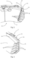
- Fig. 1 shows a partial illustration of a brake system 1 comprising a disc brake 2 and brake pads 3 and Fig. 1a illustrates an enlarged region of the brake system 1 of Fig. 1 .
- the disc brake 2 is connected to a collection device, in particular, a suction device, (not shown) for brake wear particles.
- the disc brake 2 further comprises a brake disc 4 and a non-rotatable component.
- the non-rotatable component comprises a brake carrier 5 and a brake caliper 6 configured to accommodate the brake pads 3.
- the brake carrier 5 carries the brake caliper 6, in particular, a guiding wire 12 is mounted on the brake carrier 5 and guides a connecting part 9.
- no separate brake carrier 5 is provided but the brake caliper 6 is directly attached to an axle of a vehicle.
- the brake caliper 6 comprises an actuator 7 configured to move the brake pads 3 in a direction toward the brake disc 4 for performing braking and a caliper releasing mechanism which is configured to move the brake pads 3 in a direction away from the brake disc 4 for automatically releasing the brake when the actuator 7 is deactivated.
- the caliper releasing mechanism comprises a pair of longitudinal spring elements 8, 8', the first end 8.1, 8'.1 of which is respectively joined to one of the brake pads 3 and second ends 8.2, 8'.2 of which are joined to one another by means of the connecting part 9 attached to the brake carrier 5 such that the caliper releasing mechanism is configured to be tensioned by a motion of the brake pads 3 in direction toward the brake disc 4. Therefore, the longitudinal spring elements 8, 8' are pretensioned and spread the brake pads 3 in order to avoid drag torque at the brake.
- the spring elements 8, 8' are not pretensioned and/or the second ends 8.2, 8'.2 are not joined to one another by means of the connecting part 9 but they are directly joined to one another and to the non-rotatable component.
- the longitudinal spring elements 8' on the right side of Fig. 1 and in Fig. 1a are respectively formed by a tube and the first ends 8'.1 of the tubes are respectively configured to collect brake wear particles and the second ends 8'.2 are connected to the collection device (not shown) such that the tubes are components of a brake wear removal equipment configured to collect brake wear particles and to be connectable to the collection device.
- the tubes do not form the longitudinal spring elements 8' but are provided additionally to the longitudinal spring elements 8'.
- the brake caliper 6 is provided with another component collecting bake wear particles and being connectable to a collection device, e.g. a channel made from a bent sheet metal.
- one of the caliper releasing devices on an outgoing side of the disc brake 2 has tubes being the longitudinal spring elements 8' and the other caliper releasing device has longitudinal spring elements 8 formed of wires.
- the outgoing side is this side where, when rotating in a direction of travel, the surface elements of the rotating disc brake leave the contact area of the disc brake and the brake pad.
- both caliper releasing devices are provided with tubes being the longitudinal spring elements 8'.
- the second ends 8'.2 are connected to the collection device via a pipe 10 connected to the second ends 8'.2 of the tubes via the connecting part 9 and via a flexible hose 11 joined to the pipe 10.
- the pipe 10 is designed to sustain high temperatures in this area and to avoid getting in contact with a turning rim of the brake disc 4.
- the hose 11 is designed flexible to compensate the axial displacement of the brake caliper 6 due to brake pad/brake disc wear and displacement while breaking.
- the pipe 10 and/or the hose 11 can be omitted if the component attached to the second ends 8'.2 is heat-resistant enough and has an appropriate flexibility.
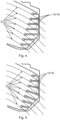
- Fig. 2 shows a partial illustration of a brake pad 3 according to a first embodiment in a first viewing direction
- Fig. 3 shows a partial illustration of the brake pad 3 according to the first embodiment in a second viewing direction.
- the brake pad 3 comprises a back plate 13 and a brake lining 14.
- the brake lining 14 is attached to the back plate 13 on an attachment face 15 of the back plate 13.
- the back plate 13 further comprises a blind hole 16 along the attachment face 15, i.e., parallel with respect to the attachment face 15.
- the blind hole 16 is formed as a bore.
- the blind hole 16 can also be formed as, e.g., a through hole with a plug, a recess in the attachment face 15 or as a recess or a bore which is not exactly parallel to the attachment face 15.
- the brake lining 14 has the shape like a segment of an annulus around a center.
- the center corresponds to a turning center of the rotatable brake disc 4.
- the brake lining 14 has another shape, e.g., a circular shape.
- the blind hole 16 is formed in a circumferential region of the back plate 13. This means that the blind hole 16 is formed close to an outside circumference of the back plate 13. In the present embodiment, the blind hole 16 is close to an end of the back plate 13 in the circumferential direction. In particular, the blind hole 16 is close to the end at the outgoing side of the brake pad 3. In alternative embodiments, several blind holds 16 are provided, in particular, on the outgoing side and on the ingoing side of the brake pad 3, i.e., in opposite circumferential regions of the back plate 13.
- the brake lining 14 comprises several channels 18 connecting the one blind hole 16 and a friction surface 17 of the brake lining 14. All of the channels 18 extend to the outside circumference of the brake lining 14 such that the channels 14 respectively form a slot 19 in the brake lining 14. For the sake of clarity, in this figure and in the subsequent figures, not all of the channels 18 and of the slots 19 are designated by a reference sign. In alternative embodiments, not all of the channels 14 but merely one or some of the channels 14 extend to the outside circumference of the brake lining 14 and respectively form one of the slots 19.
- the blind hole 16 has a central axis 21.
- the channels 18 extending to the outer circumference of the brake lining 14 are arranged such that, in a view onto the friction surface 17, a projection of each point of the central axis 21 onto the friction surface in a predefined area of the brake lining 14, which projection is virtually displaced perpendicularly with respect to the central axis 21 towards the outside circumference intersects with at least one of the slots 19. Therefore, when the brake pad 3 is oriented such that the central axis 21 of the blind hole 16 is in an almost radial direction in an installed state of the brake pad 3, a path 20 ( Figs. 4, 5 ) of each of the wear particles intersects one of the slots 19.
- Fig. 4 shows a partial illustration of the brake pad 3 according to the first embodiment in a third viewing direction and paths 20 of brake wear particles.
- the paths 20 are sections of circles around the center which correspond to the rotational axis of the brake disc 4. On these paths 20, particles adhered to the brake disc 4 move when the brake disc 4 rotates.
- Each of the path 20 intersect with at least one of the channels 18, in this embodiment, formed by the slots 19.
- the paths 20 are only exemplary paths since the particles are generated by the entire contact surface of the brake lining 14 and the brake disc 4. Therefore, in a predefined area of the brake lining 14, a projection, onto the friction surface 17, of each point of a line through the center virtually rotated around the center intersects with at least one of the channels 18.
- the predefined area is an area of the brake lining 14 where the wear particles are to be removed. Inner and outer areas in the radial direction of the brake lining 14 in the assembled state are not included in this predefined area since, when providing a channel in these inner and outer areas, there is the risk that the brake linings 14 break out in these areas.
- the slots 19 do not intersect in order not to create separated regions which could break away at the outer region of the brake lining 14.
- the slots 19 are parallel.
- Fig. 5 shows a partial illustration of the brake pad 3 according to a second embodiment and paths of wear particles.
- Fig. 5 distinguishes from the embodiment shown in Fig. 4 that the slots 19, formed by the channels 18, extending to the outer circumference of the brake lining 14, even though they also do not intersect, are not parallel. Nevertheless, all of the exemplary paths 20 of the wear particles also intersect these slots 19 formed by the channels 18.
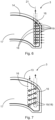
- Fig. 6 shows a partial illustration of a brake pad 3 according to a third embodiment.
- the channels 18 are arranged such that the orifices of the channels 18 connecting the blind hole 16 and the friction surface 17 are aligned in one row.
- the orifices are formed by the channels 18 connecting several blind holes 16 and the friction surface 17 and the orifices of the channels 18 connected to one of the blind holes 16 are arranged in one row.
- the row is not aligned such that is directed to the rotational axis of the brake disc 4 but the disc brake 2 is configured such that the central axis 21 of the blind hole 16 of the brake pads 3 leads past a turning centre of the rotatable brake disc 4 such that a direction of the virtual displacement differs from a tangential direction of the brake disc. Nevertheless, the slots 19 also extend parallel to the outer circumference of the brake lining 14.
- the channels 18 are arranged such that the orifices of at least two blind holes 16 are provided.
- Fig. 7 shows a partial illustration of a brake pad 3 according to a fourth embodiment.
- the channels 18 of this embodiment distinguish from the channels 18 of the preceding embodiments in that the channels 18 do not extend to the outer circumference.
- two blind holes 16 are provided in the back plate 13 so that the orifices in the friction surface 17 are aligned in two rows.
- the two blind holds 16 of this embodiment are connected by the slots 19 formed by the channels 18.
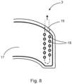
- Fig. 8 shows a partial illustration of a brake pad according to a fifth embodiment.
- the orifices of the channels 18 are arranged in two rows, nevertheless, the channels 18 connect only one blind hole 16 and the friction surface 17.
- the first ends 8'.1 ( Fig. 1 ) of the tubes are connected to the blind holes 16 of the brake pads 3 and the disc brake 2 is configured such that an open end of the blind hole 16 is arranged at an end face of the back plate 13 directed away from the turning center of the rotatable brake disc 4. Alternatively, the open end of the blind hole 16 is provided at another location of the back plate 13.
- the brake pads 3 are moved in the direction towards the brake disc 4 by the actuator 7.
- the actuator 7 is deactivated, the brake pads 3 are automatically moved in the direction away from the brake disc 4 by the caliper releasing mechanism.
- the brake wear particles are moved away from the brake pad via the channels 18 and the blind hole 16 of the brake pads 3.
Landscapes
- Engineering & Computer Science (AREA)
- General Engineering & Computer Science (AREA)
- Mechanical Engineering (AREA)
- Braking Arrangements (AREA)
Claims (20)
- Scheibenbremse (2), die mit einer drehbaren Bremsscheibe (4) und einer nicht drehbaren Komponente versehen ist, die einen Bremssattel (6) umfasst, wobeider Bremssattel (6) eine Ausrüstung zur Entfernung von Bremsverschleiß umfasst, die konfiguriert ist, um Bremsverschleißpartikel zu sammeln und mit einer Sammelvorrichtung verbindbar zu sein,die Ausrüstung zur Entfernung von Bremsverschleiß mindestens ein Rohr umfasst, von dem ein erstes Ende zum Sammeln von Bremsverschleißpartikeln konfiguriert ist und von dem ein zweites Ende mit der Sammelvorrichtung verbindbar ist, undder Bremssattel (6) zur Aufnahme von Bremsklötzen (3) konfiguriert ist, undder Bremssattel (6) Folgendes umfassteine Betätigungsvorrichtung (7), die konfiguriert ist, um die Bremsklötze (3) in eine Richtung der Bremsscheibe (4) zu bewegen, um eine Bremsung durchzuführen, undmindestens einen Sattellösemechanismus, der konfiguriert ist, um die Bremsklötze (3) in eine Richtung weg von der Bremsscheibe (4) zu bewegen, um die Bremsung zu lösen, wobeider mindestens eine Sattellösemechanismus ein Paar von länglichen Federelementen (8, 8') umfasst, von denen ein erstes Ende (8.1, 8'.1) jeweils mit einem der Bremsklötze (3) verbunden ist und von denen zweite Enden (8.2, 8'.2) miteinander und mit der nicht drehbaren Komponente verbunden sind, so dass der mindestens eine Sattellösemechanismus konfiguriert ist, um durch eine Bewegung der Bremsklötze (3) in Richtung der Bremsscheibe (4) gespannt zu werden,dadurch gekennzeichnet, dassdie länglichen Federelemente (8') jeweils von einem des mindestens einen Rohres gebildet sind, unddie ersten Enden (8'.1) der Rohre jeweils zum Sammeln von Bremsverschleißpartikeln konfiguriert sind und die zweiten Enden (8'.2) mit der Sammelvorrichtung verbindbar sind.
- Scheibenbremse (2) nach Anspruch 1, wobeidie nicht drehbare Komponente einen Bremsträger (5) umfasst, der den Bremssattel (6) trägt, unddie zweiten Enden (8'.2) der Rohre mittels eines Verbindungsteils (9), der am Bremsträger (5) befestigt ist, miteinander verbunden sind.
- Scheibenbremse (2) nach Anspruch 1 oder 2, wobei
die zweiten Enden' (8'.2) mit der Sammelvorrichtung über ein Rohr (10) verbunden sind, das mit den zweiten Enden (8'.2) der Rohre verbunden ist. - Scheibenbremse (2) nach Anspruch 2 oder 3, wobei
die zweiten Enden (8'.2) über einen flexiblen Schlauch (11) mit der Sammelvorrichtung verbunden sind. - Scheibenbremse (2) nach einem der vorstehenden Ansprüche, wobei
der Bremssattel (6) zwei Sattellösemechanismen umfasst, deren Rohre die länglichen Federelemente (8) sind. - Bremsklotz (3) für eine Scheibenbremse (2), wobei der Bremsklotz (3) Folgendes umfassteine Rückplatte (13) und einen Bremsbelag (14), wobeider Bremsbelag (14) an der Rückplatte (13) an einer Befestigungsfläche (15) der Rückplatte (13) befestigt ist,die Rückplatte (13) mindestens ein Blindloch (16) entlang der Befestigungsfläche (15) umfasst, undder Bremsbelag (14) mehrere Kanäle (18) umfasst, die ein Blindloch (16) und eine Reiboberfläche (17) des Bremsbelags (14) verbinden,dadurch gekennzeichnet, dassmindestens ein Teil der Kanäle (18) sich bis zu einem Außenumfang des Bremsbelags (14) erstreckt, so dass die Kanäle (18) jeweils einen Schlitz (19) im Bremsbelag (14) bilden.
- Bremsklotz (3) nach Anspruch 6, wobei
das mindestens eine Blindloch (16) in einem Umfangsbereich der Rückplatte (13) ausgebildet ist. - Bremsklotz (3) nach Anspruch 7, wobei
mehrere Blindlöcher (16) in gegenüberliegenden Umfangsbereichen der Rückplatte (13) ausgebildet sind. - Bremsklotz (3) nach einem der Ansprüche 6 bis 8, wobei
die Kanäle (18) so angeordnet sind, dass Öffnungen in der Reiboberfläche (17), die von den Kanälen (18) gebildet werden, in mindestens einer Reihe ausgerichtet sind. - Bremsklotz (3) nach Anspruch 9, wobeidie Öffnungen in zwei Reihen angeordnet sind unddie Kanäle (18) einer Reihe mit einem Blindloch verbunden sind.
- Bremsklotz (3) nach einem der Ansprüche 6 bis 10, wobei
alle Kanäle (18) sich bis zum Außenumfang des Bremsbelags (14) erstrecken. - Bremsklotz (3) nach einem der Ansprüche 6 bis 11, wobei
sich die Schlitze (19) nicht überschneiden, insbesondere die Schlitze (19) parallel sind. - Bremsklotz (3) nach einem der Ansprüche 10 bis 12, wobeidas Blindloch (16) eine Mittelachse (21) aufweist unddie sich zum Außenumfang erstreckenden Kanäle (18) so angeordnet sind, dass sich, in einer Sicht auf die Reiboberfläche (17), eine Projektion jedes Punktes der Mittelachse (21) auf die Reiboberfläche (17) in einem vordefinierten Bereich des Bremsbelags (14), wobei die Projektion senkrecht in Bezug auf die Mittelachse (21) zum Außenumfang hin virtuell verschoben ist, mit mindestens einem der Schlitze (19) schneidet.
- Bremsklotz (3) nach einem der Ansprüche 6 bis 12, wobeider Bremsbelag (14) die Form eines Kreisringsegments um einen Mittelpunkt aufweist, unddie Kanäle (18) so angeordnet sind, dass sich, in einer Sicht auf die Reiboberfläche (17), in einem vordefinierten Bereich des Bremsbelags (14) eine Projektion auf die Reiboberfläche (17) jedes Punktes einer Linie durch den virtuell um den Mittelpunkt gedrehten Mittelpunkt mit mindestens einem der Kanäle (18) schneidet.
- Bremssystem (1), umfassend eine Scheibenbremse (2), die mit einer Sammelvorrichtung für Verschleißpartikel verbunden ist, und Bremsklötze (3),
dadurch gekennzeichnet, dass
die Scheibenbremse (2) eine Scheibenbremse (2) nach einem der Ansprüche 1 bis 5 ist. - Bremssystem (1), umfassend eine Scheibenbremse (2), die mit einer Sammelvorrichtung für Bremsverschleißpartikel verbunden ist,
dadurch gekennzeichnet, dass
das Bremssystem (1) Bremsklötze (3) nach einem der Ansprüche 6 bis 14 umfasst. - Bremssystem (1) nach Anspruch 16, wobei die Scheibenbremse (2) eine Scheibenbremse (2) nach einem der Ansprüche 1 bis 5 umfasst.
- Bremssystem (1) nach Anspruch 17, wobei das erste Ende (8'.1) der Rohre mit dem Blindloch (16) verbunden ist.
- Bremssystem (1) nach einem der Ansprüche 16 bis 18, wobei
die Scheibenbremse (2) so konfiguriert ist, dass ein offenes Ende des Blindlochs (16) an einer von einem Drehmittelpunkt der drehbaren Bremsscheibe (2) abgewandten Endfläche der Rückplatte (13) angeordnet ist. - Bremssystem (1) nach einem der Ansprüche 16 bis 18, umfassend einen Bremsklotz (3) nach Anspruch 13, wobei
die Scheibenbremse (2) so konfiguriert ist, dass die Mittelachse (21) des Blindlochs (16) der Bremsklötze (3) über einen Drehmittelpunkt der drehbaren Bremsscheibe (2) hinaus führt, so dass sich eine Richtung einer virtuellen Verschiebung der Projektion eines jeden Punktes der Mittelachse (21) von einer tangentialen Richtung der Bremsscheibe unterscheidet.
Priority Applications (1)
| Application Number | Priority Date | Filing Date | Title |
|---|---|---|---|
| EP21204888.8A EP4174339B1 (de) | 2021-10-27 | 2021-10-27 | Scheibenbremse, bremsbelag und bremssystem, das diese scheibenbremse und bremsbeläge umfasst |
Applications Claiming Priority (1)
| Application Number | Priority Date | Filing Date | Title |
|---|---|---|---|
| EP21204888.8A EP4174339B1 (de) | 2021-10-27 | 2021-10-27 | Scheibenbremse, bremsbelag und bremssystem, das diese scheibenbremse und bremsbeläge umfasst |
Publications (2)
| Publication Number | Publication Date |
|---|---|
| EP4174339A1 EP4174339A1 (de) | 2023-05-03 |
| EP4174339B1 true EP4174339B1 (de) | 2024-08-28 |
Family
ID=78413736
Family Applications (1)
| Application Number | Title | Priority Date | Filing Date |
|---|---|---|---|
| EP21204888.8A Active EP4174339B1 (de) | 2021-10-27 | 2021-10-27 | Scheibenbremse, bremsbelag und bremssystem, das diese scheibenbremse und bremsbeläge umfasst |
Country Status (1)
| Country | Link |
|---|---|
| EP (1) | EP4174339B1 (de) |
Families Citing this family (3)
| Publication number | Priority date | Publication date | Assignee | Title |
|---|---|---|---|---|
| FR3154156A1 (fr) * | 2023-10-17 | 2025-04-18 | Tallano Technologies | Plaquette de frein |
| FR3156176A1 (fr) * | 2023-11-30 | 2025-06-06 | Tallano Technologies | Ensemble de frein pour un frein a disque |
| FR3158344A1 (fr) * | 2024-01-15 | 2025-07-18 | Tallano Technologies | Système de freinage |
Citations (4)
| Publication number | Priority date | Publication date | Assignee | Title |
|---|---|---|---|---|
| JP2005036829A (ja) | 2003-07-15 | 2005-02-10 | Mitsubishi Electric Corp | 摩擦式ブレーキ装置 |
| JP2013144585A (ja) | 2012-01-13 | 2013-07-25 | Mitsubishi Electric Corp | エレベータ巻上機用のディスクブレーキ装置及び粉塵除去方法 |
| EP3369959A1 (de) | 2015-10-30 | 2018-09-05 | Akebono Brake Industry Co., Ltd. | Scheibenbremsvorrichtung |
| EP3470700A1 (de) | 2016-06-10 | 2019-04-17 | Akebono Brake Industry Co., Ltd. | Scheibenbremsenvorrichtung |
Family Cites Families (10)
| Publication number | Priority date | Publication date | Assignee | Title |
|---|---|---|---|---|
| JP2009236221A (ja) * | 2008-03-27 | 2009-10-15 | Advics Co Ltd | 車両用ディスクブレーキ装置 |
| GB2492858C2 (en) * | 2011-12-06 | 2014-12-10 | Trevor Michael Mennie | Brake system |
| DE102016104969A1 (de) * | 2015-10-09 | 2017-04-13 | Knorr-Bremse Systeme für Nutzfahrzeuge GmbH | Scheibenbremse für ein Nutzfahrzeug |
| FR3069832B1 (fr) * | 2017-08-01 | 2019-09-06 | Tallano Technologie | Ensemble a friction pour systeme de freinage ferroviaire |
| FR3071573B1 (fr) * | 2017-09-26 | 2019-09-27 | Psa Automobiles Sa | Plaquette de frein avec collecteur de poussieres |
| FR3076876B1 (fr) | 2018-01-17 | 2020-01-03 | Tallano Technologie | Plaquette de frein pour ensemble de frein a disque comprenant une rainure d'aspiration en zone avant et une zone avant chanfreinee |
| FR3076877B1 (fr) | 2018-01-17 | 2020-01-03 | Tallano Technologie | Plaquette de frein a disque comprenant une rainure de collecte s'etendant en biais |
| DE102018120512B4 (de) * | 2018-08-22 | 2025-02-13 | Knorr-Bremse Systeme für Nutzfahrzeuge GmbH | Scheibenbremse für ein Nutzfahrzeug und Bremsbelagsatz |
| FR3094428B1 (fr) | 2019-03-28 | 2021-04-16 | Tallano Tech | Système de freinage avec soufflage dans rainure de la garniture |
| FR3094429B1 (fr) | 2019-03-28 | 2021-04-16 | Tallano Tech | Système de freinage avec aspiration centrifuge dans rainure de la garniture |
-
2021
- 2021-10-27 EP EP21204888.8A patent/EP4174339B1/de active Active
Patent Citations (4)
| Publication number | Priority date | Publication date | Assignee | Title |
|---|---|---|---|---|
| JP2005036829A (ja) | 2003-07-15 | 2005-02-10 | Mitsubishi Electric Corp | 摩擦式ブレーキ装置 |
| JP2013144585A (ja) | 2012-01-13 | 2013-07-25 | Mitsubishi Electric Corp | エレベータ巻上機用のディスクブレーキ装置及び粉塵除去方法 |
| EP3369959A1 (de) | 2015-10-30 | 2018-09-05 | Akebono Brake Industry Co., Ltd. | Scheibenbremsvorrichtung |
| EP3470700A1 (de) | 2016-06-10 | 2019-04-17 | Akebono Brake Industry Co., Ltd. | Scheibenbremsenvorrichtung |
Also Published As
| Publication number | Publication date |
|---|---|
| EP4174339A1 (de) | 2023-05-03 |
Similar Documents
| Publication | Publication Date | Title |
|---|---|---|
| EP4174339B1 (de) | Scheibenbremse, bremsbelag und bremssystem, das diese scheibenbremse und bremsbeläge umfasst | |
| JP6953522B2 (ja) | 粉塵を捕捉するためのブレーキパッド及びブレーキユニット | |
| JP7424655B2 (ja) | 粒子および粉塵の収集部を備えるブレーキパッド | |
| EP1610025B1 (de) | Verfahren zum Betreiben einer Scheibenbremsenanordnung. | |
| US20230287945A1 (en) | Brake dust particle filter, disc brake assembly and method for collecting brake dust particles | |
| WO2017073574A1 (ja) | ディスクブレーキ装置 | |
| US20230272828A1 (en) | Disk brake device and brake pad | |
| JP2006501413A (ja) | 押圧部材を備えたディスクブレーキ | |
| US20240159281A1 (en) | Disc brake and carrier | |
| JP2018533706A5 (de) | ||
| KR102815391B1 (ko) | 라이닝의 그루브에 원심 흡입이 있는 제동 시스템 | |
| US11346411B2 (en) | Braking device for vehicle | |
| JP2017082969A (ja) | ディスクブレーキ用パッド及びディスクブレーキ装置 | |
| CN114576290A (zh) | 制动器组件的护罩和刮板 | |
| SE521411C2 (sv) | Skyddslockenhet för skivbroms och skivbromsenhet inkluderande en sådan skyddslockenhet | |
| CN114466982A (zh) | 铁路车辆用制动盘单元 | |
| US9062725B2 (en) | Brake assembly | |
| CA3050993C (en) | Brake shoe, system for modular assembly of a brake shoe, brake apparatus and method for producing a brake shoe | |
| JP2023123867A (ja) | 鉄道車両用ブレーキライニング | |
| CN113631458B (zh) | 铁道车辆用制动器摩擦衬片 | |
| US10047809B2 (en) | Drum brake dust shield for a vehicle braking system | |
| US20250383000A1 (en) | Brake pads | |
| US20240401652A1 (en) | Brake apparatus | |
| EP4480764A1 (de) | Bremsstaubsammler | |
| CA3038425C (en) | Brake pad and braking unit for capturing particles |
Legal Events
| Date | Code | Title | Description |
|---|---|---|---|
| PUAI | Public reference made under article 153(3) epc to a published international application that has entered the european phase |
Free format text: ORIGINAL CODE: 0009012 |
|
| STAA | Information on the status of an ep patent application or granted ep patent |
Free format text: STATUS: THE APPLICATION HAS BEEN PUBLISHED |
|
| AK | Designated contracting states |
Kind code of ref document: A1 Designated state(s): AL AT BE BG CH CY CZ DE DK EE ES FI FR GB GR HR HU IE IS IT LI LT LU LV MC MK MT NL NO PL PT RO RS SE SI SK SM TR |
|
| STAA | Information on the status of an ep patent application or granted ep patent |
Free format text: STATUS: REQUEST FOR EXAMINATION WAS MADE |
|
| 17P | Request for examination filed |
Effective date: 20231103 |
|
| RBV | Designated contracting states (corrected) |
Designated state(s): AL AT BE BG CH CY CZ DE DK EE ES FI FR GB GR HR HU IE IS IT LI LT LU LV MC MK MT NL NO PL PT RO RS SE SI SK SM TR |
|
| RAP3 | Party data changed (applicant data changed or rights of an application transferred) |
Owner name: KNORR-BREMSE SYSTEME FUER NUTZFAHRZEUGE GMBH |
|
| RIC1 | Information provided on ipc code assigned before grant |
Ipc: F16D 65/092 20060101ALI20240409BHEP Ipc: F16D 65/00 20060101AFI20240409BHEP |
|
| GRAP | Despatch of communication of intention to grant a patent |
Free format text: ORIGINAL CODE: EPIDOSNIGR1 |
|
| STAA | Information on the status of an ep patent application or granted ep patent |
Free format text: STATUS: GRANT OF PATENT IS INTENDED |
|
| INTG | Intention to grant announced |
Effective date: 20240528 |
|
| GRAS | Grant fee paid |
Free format text: ORIGINAL CODE: EPIDOSNIGR3 |
|
| GRAA | (expected) grant |
Free format text: ORIGINAL CODE: 0009210 |
|
| STAA | Information on the status of an ep patent application or granted ep patent |
Free format text: STATUS: THE PATENT HAS BEEN GRANTED |
|
| AK | Designated contracting states |
Kind code of ref document: B1 Designated state(s): AL AT BE BG CH CY CZ DE DK EE ES FI FR GB GR HR HU IE IS IT LI LT LU LV MC MK MT NL NO PL PT RO RS SE SI SK SM TR |
|
| REG | Reference to a national code |
Ref country code: CH Ref legal event code: EP |
|
| REG | Reference to a national code |
Ref country code: DE Ref legal event code: R096 Ref document number: 602021017841 Country of ref document: DE |
|
| REG | Reference to a national code |
Ref country code: IE Ref legal event code: FG4D |
|
| REG | Reference to a national code |
Ref country code: SE Ref legal event code: TRGR |
|
| REG | Reference to a national code |
Ref country code: LT Ref legal event code: MG9D |
|
| PGFP | Annual fee paid to national office [announced via postgrant information from national office to epo] |
Ref country code: DE Payment date: 20241029 Year of fee payment: 4 |
|
| PG25 | Lapsed in a contracting state [announced via postgrant information from national office to epo] |
Ref country code: NO Free format text: LAPSE BECAUSE OF FAILURE TO SUBMIT A TRANSLATION OF THE DESCRIPTION OR TO PAY THE FEE WITHIN THE PRESCRIBED TIME-LIMIT Effective date: 20241128 |
|
| REG | Reference to a national code |
Ref country code: AT Ref legal event code: MK05 Ref document number: 1718246 Country of ref document: AT Kind code of ref document: T Effective date: 20240828 |
|
| PG25 | Lapsed in a contracting state [announced via postgrant information from national office to epo] |
Ref country code: NL Free format text: LAPSE BECAUSE OF FAILURE TO SUBMIT A TRANSLATION OF THE DESCRIPTION OR TO PAY THE FEE WITHIN THE PRESCRIBED TIME-LIMIT Effective date: 20240828 Ref country code: PL Free format text: LAPSE BECAUSE OF FAILURE TO SUBMIT A TRANSLATION OF THE DESCRIPTION OR TO PAY THE FEE WITHIN THE PRESCRIBED TIME-LIMIT Effective date: 20240828 Ref country code: GR Free format text: LAPSE BECAUSE OF FAILURE TO SUBMIT A TRANSLATION OF THE DESCRIPTION OR TO PAY THE FEE WITHIN THE PRESCRIBED TIME-LIMIT Effective date: 20241129 Ref country code: FI Free format text: LAPSE BECAUSE OF FAILURE TO SUBMIT A TRANSLATION OF THE DESCRIPTION OR TO PAY THE FEE WITHIN THE PRESCRIBED TIME-LIMIT Effective date: 20240828 Ref country code: PT Free format text: LAPSE BECAUSE OF FAILURE TO SUBMIT A TRANSLATION OF THE DESCRIPTION OR TO PAY THE FEE WITHIN THE PRESCRIBED TIME-LIMIT Effective date: 20241230 |
|
| PG25 | Lapsed in a contracting state [announced via postgrant information from national office to epo] |
Ref country code: BG Free format text: LAPSE BECAUSE OF FAILURE TO SUBMIT A TRANSLATION OF THE DESCRIPTION OR TO PAY THE FEE WITHIN THE PRESCRIBED TIME-LIMIT Effective date: 20240828 |
|
| PG25 | Lapsed in a contracting state [announced via postgrant information from national office to epo] |
Ref country code: LV Free format text: LAPSE BECAUSE OF FAILURE TO SUBMIT A TRANSLATION OF THE DESCRIPTION OR TO PAY THE FEE WITHIN THE PRESCRIBED TIME-LIMIT Effective date: 20240828 |
|
| REG | Reference to a national code |
Ref country code: NL Ref legal event code: MP Effective date: 20240828 |
|
| PG25 | Lapsed in a contracting state [announced via postgrant information from national office to epo] |
Ref country code: AT Free format text: LAPSE BECAUSE OF FAILURE TO SUBMIT A TRANSLATION OF THE DESCRIPTION OR TO PAY THE FEE WITHIN THE PRESCRIBED TIME-LIMIT Effective date: 20240828 Ref country code: IS Free format text: LAPSE BECAUSE OF FAILURE TO SUBMIT A TRANSLATION OF THE DESCRIPTION OR TO PAY THE FEE WITHIN THE PRESCRIBED TIME-LIMIT Effective date: 20241228 |
|
| PG25 | Lapsed in a contracting state [announced via postgrant information from national office to epo] |
Ref country code: HR Free format text: LAPSE BECAUSE OF FAILURE TO SUBMIT A TRANSLATION OF THE DESCRIPTION OR TO PAY THE FEE WITHIN THE PRESCRIBED TIME-LIMIT Effective date: 20240828 |
|
| PG25 | Lapsed in a contracting state [announced via postgrant information from national office to epo] |
Ref country code: RS Free format text: LAPSE BECAUSE OF FAILURE TO SUBMIT A TRANSLATION OF THE DESCRIPTION OR TO PAY THE FEE WITHIN THE PRESCRIBED TIME-LIMIT Effective date: 20241128 Ref country code: ES Free format text: LAPSE BECAUSE OF FAILURE TO SUBMIT A TRANSLATION OF THE DESCRIPTION OR TO PAY THE FEE WITHIN THE PRESCRIBED TIME-LIMIT Effective date: 20240828 |
|
| PGFP | Annual fee paid to national office [announced via postgrant information from national office to epo] |
Ref country code: SE Payment date: 20241025 Year of fee payment: 4 |
|
| PG25 | Lapsed in a contracting state [announced via postgrant information from national office to epo] |
Ref country code: RS Free format text: LAPSE BECAUSE OF FAILURE TO SUBMIT A TRANSLATION OF THE DESCRIPTION OR TO PAY THE FEE WITHIN THE PRESCRIBED TIME-LIMIT Effective date: 20241128 Ref country code: PT Free format text: LAPSE BECAUSE OF FAILURE TO SUBMIT A TRANSLATION OF THE DESCRIPTION OR TO PAY THE FEE WITHIN THE PRESCRIBED TIME-LIMIT Effective date: 20241230 Ref country code: PL Free format text: LAPSE BECAUSE OF FAILURE TO SUBMIT A TRANSLATION OF THE DESCRIPTION OR TO PAY THE FEE WITHIN THE PRESCRIBED TIME-LIMIT Effective date: 20240828 Ref country code: NO Free format text: LAPSE BECAUSE OF FAILURE TO SUBMIT A TRANSLATION OF THE DESCRIPTION OR TO PAY THE FEE WITHIN THE PRESCRIBED TIME-LIMIT Effective date: 20241128 Ref country code: NL Free format text: LAPSE BECAUSE OF FAILURE TO SUBMIT A TRANSLATION OF THE DESCRIPTION OR TO PAY THE FEE WITHIN THE PRESCRIBED TIME-LIMIT Effective date: 20240828 Ref country code: LV Free format text: LAPSE BECAUSE OF FAILURE TO SUBMIT A TRANSLATION OF THE DESCRIPTION OR TO PAY THE FEE WITHIN THE PRESCRIBED TIME-LIMIT Effective date: 20240828 Ref country code: IS Free format text: LAPSE BECAUSE OF FAILURE TO SUBMIT A TRANSLATION OF THE DESCRIPTION OR TO PAY THE FEE WITHIN THE PRESCRIBED TIME-LIMIT Effective date: 20241228 Ref country code: HR Free format text: LAPSE BECAUSE OF FAILURE TO SUBMIT A TRANSLATION OF THE DESCRIPTION OR TO PAY THE FEE WITHIN THE PRESCRIBED TIME-LIMIT Effective date: 20240828 Ref country code: GR Free format text: LAPSE BECAUSE OF FAILURE TO SUBMIT A TRANSLATION OF THE DESCRIPTION OR TO PAY THE FEE WITHIN THE PRESCRIBED TIME-LIMIT Effective date: 20241129 Ref country code: FI Free format text: LAPSE BECAUSE OF FAILURE TO SUBMIT A TRANSLATION OF THE DESCRIPTION OR TO PAY THE FEE WITHIN THE PRESCRIBED TIME-LIMIT Effective date: 20240828 Ref country code: ES Free format text: LAPSE BECAUSE OF FAILURE TO SUBMIT A TRANSLATION OF THE DESCRIPTION OR TO PAY THE FEE WITHIN THE PRESCRIBED TIME-LIMIT Effective date: 20240828 Ref country code: BG Free format text: LAPSE BECAUSE OF FAILURE TO SUBMIT A TRANSLATION OF THE DESCRIPTION OR TO PAY THE FEE WITHIN THE PRESCRIBED TIME-LIMIT Effective date: 20240828 Ref country code: AT Free format text: LAPSE BECAUSE OF FAILURE TO SUBMIT A TRANSLATION OF THE DESCRIPTION OR TO PAY THE FEE WITHIN THE PRESCRIBED TIME-LIMIT Effective date: 20240828 |
|
| PG25 | Lapsed in a contracting state [announced via postgrant information from national office to epo] |
Ref country code: SM Free format text: LAPSE BECAUSE OF FAILURE TO SUBMIT A TRANSLATION OF THE DESCRIPTION OR TO PAY THE FEE WITHIN THE PRESCRIBED TIME-LIMIT Effective date: 20240828 Ref country code: RO Free format text: LAPSE BECAUSE OF FAILURE TO SUBMIT A TRANSLATION OF THE DESCRIPTION OR TO PAY THE FEE WITHIN THE PRESCRIBED TIME-LIMIT Effective date: 20240828 Ref country code: DK Free format text: LAPSE BECAUSE OF FAILURE TO SUBMIT A TRANSLATION OF THE DESCRIPTION OR TO PAY THE FEE WITHIN THE PRESCRIBED TIME-LIMIT Effective date: 20240828 |
|
| PG25 | Lapsed in a contracting state [announced via postgrant information from national office to epo] |
Ref country code: EE Free format text: LAPSE BECAUSE OF FAILURE TO SUBMIT A TRANSLATION OF THE DESCRIPTION OR TO PAY THE FEE WITHIN THE PRESCRIBED TIME-LIMIT Effective date: 20240828 |
|
| PG25 | Lapsed in a contracting state [announced via postgrant information from national office to epo] |
Ref country code: CZ Free format text: LAPSE BECAUSE OF FAILURE TO SUBMIT A TRANSLATION OF THE DESCRIPTION OR TO PAY THE FEE WITHIN THE PRESCRIBED TIME-LIMIT Effective date: 20240828 |
|
| PG25 | Lapsed in a contracting state [announced via postgrant information from national office to epo] |
Ref country code: IT Free format text: LAPSE BECAUSE OF FAILURE TO SUBMIT A TRANSLATION OF THE DESCRIPTION OR TO PAY THE FEE WITHIN THE PRESCRIBED TIME-LIMIT Effective date: 20240828 Ref country code: SK Free format text: LAPSE BECAUSE OF FAILURE TO SUBMIT A TRANSLATION OF THE DESCRIPTION OR TO PAY THE FEE WITHIN THE PRESCRIBED TIME-LIMIT Effective date: 20240828 |
|
| REG | Reference to a national code |
Ref country code: DE Ref legal event code: R026 Ref document number: 602021017841 Country of ref document: DE |
|
| PLBI | Opposition filed |
Free format text: ORIGINAL CODE: 0009260 |
|
| PLAB | Opposition data, opponent's data or that of the opponent's representative modified |
Free format text: ORIGINAL CODE: 0009299OPPO |
|
| REG | Reference to a national code |
Ref country code: CH Ref legal event code: PL |
|
| PLAX | Notice of opposition and request to file observation + time limit sent |
Free format text: ORIGINAL CODE: EPIDOSNOBS2 |
|
| 26 | Opposition filed |
Opponent name: VRI-PATENT MONITORING ASSOCIATION Effective date: 20250522 |
|
| R26 | Opposition filed (corrected) |
Opponent name: VRI-PATENT MONITORING ASSOCIATION Effective date: 20250522 |
|
| PG25 | Lapsed in a contracting state [announced via postgrant information from national office to epo] |
Ref country code: MC Free format text: LAPSE BECAUSE OF FAILURE TO SUBMIT A TRANSLATION OF THE DESCRIPTION OR TO PAY THE FEE WITHIN THE PRESCRIBED TIME-LIMIT Effective date: 20240828 |
|
| PG25 | Lapsed in a contracting state [announced via postgrant information from national office to epo] |
Ref country code: LU Free format text: LAPSE BECAUSE OF NON-PAYMENT OF DUE FEES Effective date: 20241027 Ref country code: BE Free format text: LAPSE BECAUSE OF NON-PAYMENT OF DUE FEES Effective date: 20241031 |
|
| PG25 | Lapsed in a contracting state [announced via postgrant information from national office to epo] |
Ref country code: FR Free format text: LAPSE BECAUSE OF NON-PAYMENT OF DUE FEES Effective date: 20241028 |
|
| PG25 | Lapsed in a contracting state [announced via postgrant information from national office to epo] |
Ref country code: CH Free format text: LAPSE BECAUSE OF NON-PAYMENT OF DUE FEES Effective date: 20241031 |
|
| REG | Reference to a national code |
Ref country code: BE Ref legal event code: MM Effective date: 20241031 |
|
| PG25 | Lapsed in a contracting state [announced via postgrant information from national office to epo] |
Ref country code: IE Free format text: LAPSE BECAUSE OF NON-PAYMENT OF DUE FEES Effective date: 20241027 |