EP4173665A1 - Method for manufacturing a headgear assembly for a respiratory interface - Google Patents
Method for manufacturing a headgear assembly for a respiratory interface Download PDFInfo
- Publication number
- EP4173665A1 EP4173665A1 EP22200594.4A EP22200594A EP4173665A1 EP 4173665 A1 EP4173665 A1 EP 4173665A1 EP 22200594 A EP22200594 A EP 22200594A EP 4173665 A1 EP4173665 A1 EP 4173665A1
- Authority
- EP
- European Patent Office
- Prior art keywords
- substrate
- textile
- substrates
- textile casing
- junction portion
- Prior art date
- Legal status (The legal status is an assumption and is not a legal conclusion. Google has not performed a legal analysis and makes no representation as to the accuracy of the status listed.)
- Pending
Links
- 238000000034 method Methods 0.000 title description 21
- 238000004519 manufacturing process Methods 0.000 title description 7
- 230000000241 respiratory effect Effects 0.000 title description 7
- 239000000758 substrate Substances 0.000 claims abstract description 444
- 239000004753 textile Substances 0.000 claims abstract description 255
- 239000004033 plastic Substances 0.000 claims description 49
- 239000000463 material Substances 0.000 claims description 36
- 230000007246 mechanism Effects 0.000 abstract description 24
- 239000011162 core material Substances 0.000 description 55
- 238000000465 moulding Methods 0.000 description 27
- 239000000203 mixture Substances 0.000 description 7
- 238000009472 formulation Methods 0.000 description 5
- 230000008569 process Effects 0.000 description 5
- 238000002347 injection Methods 0.000 description 4
- 239000007924 injection Substances 0.000 description 4
- 238000001746 injection moulding Methods 0.000 description 4
- 238000012986 modification Methods 0.000 description 4
- 230000004048 modification Effects 0.000 description 4
- 239000002991 molded plastic Substances 0.000 description 4
- 230000029058 respiratory gaseous exchange Effects 0.000 description 4
- 230000008901 benefit Effects 0.000 description 3
- 238000005259 measurement Methods 0.000 description 3
- 230000002441 reversible effect Effects 0.000 description 3
- 238000010276 construction Methods 0.000 description 2
- 239000013013 elastic material Substances 0.000 description 2
- 238000003780 insertion Methods 0.000 description 2
- 230000037431 insertion Effects 0.000 description 2
- 238000002560 therapeutic procedure Methods 0.000 description 2
- 229920002725 thermoplastic elastomer Polymers 0.000 description 2
- 229920001410 Microfiber Polymers 0.000 description 1
- 239000004677 Nylon Substances 0.000 description 1
- 239000004743 Polypropylene Substances 0.000 description 1
- 239000000853 adhesive Substances 0.000 description 1
- 230000001070 adhesive effect Effects 0.000 description 1
- 230000009286 beneficial effect Effects 0.000 description 1
- 230000015572 biosynthetic process Effects 0.000 description 1
- 238000006243 chemical reaction Methods 0.000 description 1
- 239000002131 composite material Substances 0.000 description 1
- 238000005520 cutting process Methods 0.000 description 1
- 230000007423 decrease Effects 0.000 description 1
- 230000003467 diminishing effect Effects 0.000 description 1
- 230000000694 effects Effects 0.000 description 1
- 230000008676 import Effects 0.000 description 1
- 238000010348 incorporation Methods 0.000 description 1
- 238000005304 joining Methods 0.000 description 1
- 239000003658 microfiber Substances 0.000 description 1
- 229920001778 nylon Polymers 0.000 description 1
- 230000001936 parietal effect Effects 0.000 description 1
- 230000008447 perception Effects 0.000 description 1
- 230000002093 peripheral effect Effects 0.000 description 1
- 230000000704 physical effect Effects 0.000 description 1
- -1 polypropylene Polymers 0.000 description 1
- 229920001155 polypropylene Polymers 0.000 description 1
- 229920001296 polysiloxane Polymers 0.000 description 1
- 238000004080 punching Methods 0.000 description 1
- 230000004044 response Effects 0.000 description 1
- 230000000717 retained effect Effects 0.000 description 1
- 239000007787 solid Substances 0.000 description 1
- 229920001187 thermosetting polymer Polymers 0.000 description 1
- 238000003466 welding Methods 0.000 description 1
- 230000037303 wrinkles Effects 0.000 description 1
Images


Classifications
-
- A—HUMAN NECESSITIES
- A61—MEDICAL OR VETERINARY SCIENCE; HYGIENE
- A61M—DEVICES FOR INTRODUCING MEDIA INTO, OR ONTO, THE BODY; DEVICES FOR TRANSDUCING BODY MEDIA OR FOR TAKING MEDIA FROM THE BODY; DEVICES FOR PRODUCING OR ENDING SLEEP OR STUPOR
- A61M16/00—Devices for influencing the respiratory system of patients by gas treatment, e.g. mouth-to-mouth respiration; Tracheal tubes
- A61M16/06—Respiratory or anaesthetic masks
- A61M16/0683—Holding devices therefor
-
- A—HUMAN NECESSITIES
- A62—LIFE-SAVING; FIRE-FIGHTING
- A62B—DEVICES, APPARATUS OR METHODS FOR LIFE-SAVING
- A62B18/00—Breathing masks or helmets, e.g. affording protection against chemical agents or for use at high altitudes or incorporating a pump or compressor for reducing the inhalation effort
- A62B18/08—Component parts for gas-masks or gas-helmets, e.g. windows, straps, speech transmitters, signal-devices
- A62B18/084—Means for fastening gas-masks to heads or helmets
-
- A—HUMAN NECESSITIES
- A61—MEDICAL OR VETERINARY SCIENCE; HYGIENE
- A61M—DEVICES FOR INTRODUCING MEDIA INTO, OR ONTO, THE BODY; DEVICES FOR TRANSDUCING BODY MEDIA OR FOR TAKING MEDIA FROM THE BODY; DEVICES FOR PRODUCING OR ENDING SLEEP OR STUPOR
- A61M16/00—Devices for influencing the respiratory system of patients by gas treatment, e.g. mouth-to-mouth respiration; Tracheal tubes
- A61M16/06—Respiratory or anaesthetic masks
- A61M16/0605—Means for improving the adaptation of the mask to the patient
- A61M16/0633—Means for improving the adaptation of the mask to the patient with forehead support
-
- A—HUMAN NECESSITIES
- A61—MEDICAL OR VETERINARY SCIENCE; HYGIENE
- A61M—DEVICES FOR INTRODUCING MEDIA INTO, OR ONTO, THE BODY; DEVICES FOR TRANSDUCING BODY MEDIA OR FOR TAKING MEDIA FROM THE BODY; DEVICES FOR PRODUCING OR ENDING SLEEP OR STUPOR
- A61M2207/00—Methods of manufacture, assembly or production
-
- A—HUMAN NECESSITIES
- A61—MEDICAL OR VETERINARY SCIENCE; HYGIENE
- A61M—DEVICES FOR INTRODUCING MEDIA INTO, OR ONTO, THE BODY; DEVICES FOR TRANSDUCING BODY MEDIA OR FOR TAKING MEDIA FROM THE BODY; DEVICES FOR PRODUCING OR ENDING SLEEP OR STUPOR
- A61M2210/00—Anatomical parts of the body
- A61M2210/06—Head
- A61M2210/0618—Nose
Landscapes
- Health & Medical Sciences (AREA)
- General Health & Medical Sciences (AREA)
- Pulmonology (AREA)
- Life Sciences & Earth Sciences (AREA)
- Emergency Medicine (AREA)
- Biomedical Technology (AREA)
- Heart & Thoracic Surgery (AREA)
- Hematology (AREA)
- Engineering & Computer Science (AREA)
- Animal Behavior & Ethology (AREA)
- Anesthesiology (AREA)
- Public Health (AREA)
- Veterinary Medicine (AREA)
- Business, Economics & Management (AREA)
- Emergency Management (AREA)
- Helmets And Other Head Coverings (AREA)
- Knitting Of Fabric (AREA)
- Data Exchanges In Wide-Area Networks (AREA)
- Materials For Photolithography (AREA)
Abstract
Description
- This application is related to and claims priority from
U.S. Provisional Patent Application No. 62/309,405 - The present disclosure generally relates to headgear for use in combination with a breathing apparatus. More particularly, the present disclosure relates to a system and method for intra-moulding a headgear arrangement having an improved edge finish and improved manufacturability.
- The treatment of respiratory ailments or conditions with therapies, such as NIV, Bi-level or CPAP, involves the delivery of pressurized air to the airways of a human via a conduit and a breathing apparatus (e.g., a mask or cannula). Typically, a mask creates at least a substantial "seal" on or around the nose and/or the mouth of a user. The mask is connected to and supported by a headgear arrangement that is worn on the head of the user. The headgear arrangement comprises a series of straps that pass around the back and/or top of a user's head and also which support the mask against the user's nose and/or the mouth.
- Headgear arrangements may be formed using an intra-moulding technique as disclosed in
U.S. Patent Application 14/856502 , which is herein incorporated by reference. Accordingly, the headgear arrangements have a plastic core that is surrounded by a textile layer or casing. The headgear arrangements are typically formed by inserting inner and outer textile layers into a molding tool, closing the tool, and injecting plastic between the inner and outer textile layers. Generally, the headgear arrangements have a junction portion where multiple straps intersect and are connected. That is, in the headgear arrangements, the top strap, the rear strap, and the side straps are connected at the junction portion. The junction portion has a substantially triangular profile region with multiple curved segment edges and truncated corners from which straps may extend, in some configurations. As a result of their shape, the junction portions are difficult to manufacture. More specifically, the non-linear shape and geometry of the junction portion makes it difficult to wrap the textile layers around the plastic core because it is difficult to align and secure loose textile layers within a mould tool cavity prior to closing the mould. Further, the inner and outer textile layers may move out of position relative to the mould when the mould tool is closed or can be pushed out of position by the pressure of the injected plastic material. Therefore, it is desirable to provide a headgear strap having a construction that is easier and more reliable to intra-moulded. - The systems, methods and devices described herein have innovative aspects, no single one of which is indispensable or solely responsible for their desirable attributes. Without limiting the scope of the claims, some of the advantageous features will now be summarized.
- In accordance with at least one of the embodiments disclosed herein, a headgear strap for a headgear assembly is disclosed. The headgear strap includes a first substrate, a second substrate attached to the first substrate, a first textile casing attached to the first substrate, a second textile casing attached to the second substrate, and an intra-moulded core positioned between the first and second textile casings. The first and second substrates, the first and second textile casings and the intra-moulded core are formed as an integral structure by the application of a molten plastic material between the first and second textile casings.
- According to a further aspect, the first textile casing covers an inwardly-facing surface of the headgear assembly and the second textile casing covers an outwardly-facing the surface of the headgear assembly.
- According to a further aspect, the ends of the first and second textile casing are positioned between the first and second substrates.
- According to a further aspect, each of the first and second substrates include a first retaining structure, and each of the first and second textile casings include a second retaining structure, wherein the first and second retaining features are configured to engage each other to attach the first textile casing onto the first substrate and the second textile casing onto the second substrate.
- According to a further aspect, the first retaining structure of the first substrate engages the first retaining structure of the second substrate to connect the first and second substrates.
- According to a further aspect, the first retaining structure includes a post protruding outward from a surface of at least one of the first and second substrates, and a socket positioned on at least an other of the first and second substrates, the socket having an inner hole, wherein the post is positioned within the inner hole to connect the first and second substrates.
- According to a further aspect, the socket protrudes outward from a surface of the other of the first and second substrates.
- According to a further aspect, the second retaining structure includes at least one hole extending through each of the first and second textile casings, wherein at least one of the post and the socket engages the hole to attach the first textile casing on the first substrate and the second textile casing on the second substrate.
- According to a further aspect, the second retaining structure is positioned on portions of the first and second textile casing that are positioned between the first and second substrates.
- According to a further aspect, a strap connector is preformed in at least one of the first and second substrates.
- According to a further aspect, a length adjustment mechanism is preformed in at least one of the first and second substrates.
- According to a further aspect, an angular adjustment mechanism is preformed in at least one of the first and second substrates.
- According to a further aspect, at least one of the first and second substrates includes a gate.
- According to a further aspect, the first and second substrates are identical.
- According to a further aspect, the intra-moulded core comprises an injection moulded plastic material that is injected between the first and second textile casings.
- In accordance with at least another of the embodiments disclosed herein, a headgear strap assembly is disclosed. The headgear strap assembly includes a substrate having an outer surface and an inner surface that is opposite the outer surface, and a textile casing overlaid onto the outer surface of the substrate. The textile casing has a width that is greater than a width of the substrate.
- According to a further aspect, the textile casing includes an overhanging portion that extends beyond edges of the outer surface of the substrate, and the overhanging portion is configured to be folded over the edges onto the inner surface of the substrate.
- According to a further aspect, the substrate includes a first retaining structure, and the textile casing includes a second retaining structure, wherein the first and second retaining features are configured to engage each other to attach the textile casing to the substrate.
- According to a further aspect, the first retaining structure includes a post protruding outward from the inner surface of the substrate.
- According to a further aspect, the first retaining structure includes a socket protruding outward from the inner surface of the substrate, the socket having an inner hole extending through the socket.
- According to a further aspect, the second retaining structure includes at least one hole extending through the textile casing, wherein at least one of the post and the socket engages the hole to attach the textile casing onto the substrate.
- According to a further aspect, the second retaining structure is positioned on the overhanging portion of the textile casing.
- In accordance with at least another of the embodiments disclosed herein, a method for forming a headgear assembly for a respiratory interface is disclosed. The method includes securing textile casings onto an outer portion of each of a pair of substrates, connecting the pair of substrates along an inner portion of each of the pair of substrates, positioning the pair of substrates within a moulding tool, injecting molten plastic material between the pair of substrates, and allowing the molten plastic material to solidify to form a plastic core between the textile casings.
- According to a further aspect, securing the textile casing includes folding the textile casing over ends of each of the pair of substrates such that ends of the textile casing are positioned between the pair of substrates.
- According to a further aspect, securing the textile casing includes fastening the ends of the textile casing to the inner portion of each of the pair of substrates.
- According to a further aspect, connecting the pair of substrates includes interlocking the inner portions of the pair of substrates.
- According to a further aspect, the pair of substrates are preformed unitarily as an integral structure.
- According to a further aspect, the pair of substrates and molten plastic material chemically bond to provide a uniform plastic core between the textile casings.
- In accordance with at least another of the embodiments disclosed herein, a junction portion in a headgear assembly at which two or more straps of the headgear assembly connect is disclosed. The junction portion includes a first substrate; a second substrate attached to the first substrate; a first textile casing attached to the first substrate; a second textile casing attached to the second substrate; and a plastic core that is surrounded by the first and second textile casings and is bonded to the first and second substrates and the first and second textile casings.
- According to a further aspect, the first textile casing covers an inwardly-facing surface of the headgear assembly and the second textile casing covers an outwardly-facing the surface of the headgear assembly.
- According to a further aspect, the ends of the first and second textile casing are positioned between the first and second substrates.
- According to a further aspect, each of the first and second substrates include a first retaining structure, and each of the first and second textile casings include a second retaining structure, wherein the first and second retaining features are configured to engage each other to attach the first textile casing onto the first substrate and the second textile casing onto the second substrate.
- According to a further aspect, the first retaining structure of the first substrate engages the first retaining structure of the second substrate to connect the first and second substrates.
- According to a further aspect, the first retaining structure includes a post protruding outward from a surface of at least one of the first and second substrates, and a socket positioned on at least an other of the first and second substrates, the socket having an inner hole, wherein the post is positioned within the inner hole to connect the first and second substrates.
- According to a further aspect, the socket protrudes outward from a surface of the other of the first and second substrates.
- According to a further aspect, the second retaining structure includes at least one hole extending through each of the first and second textile casings, wherein at least one of the post and the socket engages the hole to attach the first textile casing on the first substrate and the second textile casing on the second substrate.
- According to a further aspect, the second retaining structure is positioned on portions of the first and second textile casing that are positioned between the first and second substrates.
- According to a further aspect, the junction portion further includes a strap connector preformed in at least one of the first and second substrates.
- According to a further aspect, the junction portion further includes a length adjustment mechanism preformed in at least one of the first and second substrates.
- According to a further aspect, the junction portion further includes an angular adjustment mechanism preformed in at least one of the first and second substrates.
- According to a further aspect, at least one of the first and second substrates includes a gate.
- According to a further aspect, the first and second substrates are identical.
- According to a further aspect, the plastic core comprises an injection moulded plastic material that is injected between the first and second textile casings.
- Throughout the drawings, reference numbers can be reused to indicate general correspondence between reference elements. The drawings are provided to illustrate example embodiments described herein and are not intended to limit the scope of the disclosure.
-
Figure 1A illustrates a side view of a headgear arrangement formed by the intra-moulding arrangement of the present disclosure. -
Figure 1B illustrates a side view of an alternative headgear arrangement formed by the intra-moulding arrangement of the present disclosure. -
Figure 1C illustrates a side view of another alternative headgear arrangement formed by the intra-moulding arrangement of the present disclosure. -
Figure 1D illustrates a side view of a further alternative headgear arrangement formed by the intra-moulding arrangement of the present disclosure. -
Figure 2A illustrates a top perspective view of a junction portion of a headgear formed by the intra-moulding arrangement of the present disclosure. -
Figure 2B illustrates a top perspective view of a textile casing and a substrate for forming the junction portion ofFigure 2A . -
Figure 3A illustrates a top view of the substrate. -
Figure 3B illustrates a cross-sectional view of the substrate along aline 3B-3B inFigure 3A . -
Figure 4 illustrates a top view of the substrate overlaid onto the textile casing. -
Figure 5A illustrates a top view of the textile casing being folded over the substrate. -
Figure 5B illustrates a top view of the textile casing entirely folded over the substrate. -
Figure 6A illustrates a top perspective view of the junction portion formed by connecting a pair of substrates. -
Figure 6B illustrates a rotated top perspective view of the junction portion formed by connecting a pair of substrates. -
Figure 6C illustrates a cross-sectional view of a pair of substrates having posts and sockets in alignment. -
Figure 7A illustrates a top view of the junction portion formed by the intra-moulding arrangement of the present disclosure. -
Figure 7B illustrates a side profile view of the junction portion formed by the intra-moulding arrangement of the present disclosure. -
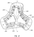
Figure 8 illustrates a top view of an alternative reversible or modular substrate arrangement. -
Figure 9 illustrates a top view of an alternative substrate arrangement having a hook for retaining the textile casing. -
Figure 10A illustrates a top view of an alternative substrate arrangement having an insert within an aperture of the substrate. -
Figure 10B illustrates a cross-sectional view of the alternative substrate arrangement along a line B-B ofFigure 10A having an insert positioned within the aperture of the substrate. -
Figure 10C illustrates a cross-sectional view of an alternative substrate arrangement along a line B-B ofFigure 10A having a textile covered insert positioned within the aperture of the substrate. -
Figure 11 illustrates a top view of an alternative substrate arrangement for forming a headgear strap. -
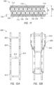
Figure 12A illustrates a top view of an alternative substrate arrangement for forming a headgear strap having an alternative post and socket arrangement. -
Figure 12B illustrates a top view of the alternative substrate arrangement inFigure 12A having a textile casing applied to a substrate. -
Figure 12C illustrates a cross-sectional view of the substrate inFigure 12A . -
Figure 12D illustrates a cross-sectional view of the substrate inFigure 12A having edge rails and crossbars with a uniform thickness. -
Figure 12E illustrates a cross-sectional view of the alternative substrate arrangement inFigure 12A prior to intra-moulding. -
Figure 12F illustrates a cross-sectional view of the alternative substrate arrangement inFigure 12A after intra-moulding. -
Figure 13 illustrates a top view of an alternative substrate arrangement having connectors preformed into the substrate. -
Figure 14 illustrates a top view of an alternative substrate arrangement for forming a strap of a headgear having an integrally formed length adjustment mechanism. -
Figure 15 illustrates a top view of an alternative substrate arrangement for forming a junction portion of a headgear having an integrally formed angular adjustment mechanism. - Embodiments of systems, components and methods of assembly and manufacture will now be described with reference to the accompanying figures, wherein like numerals refer to like or similar elements throughout. Although several embodiments, examples and illustrations are disclosed below, it will be understood by those of ordinary skill in the art that the inventions described herein extends beyond the specifically disclosed embodiments, examples and illustrations, and can include other uses of the inventions and obvious modifications and equivalents thereof. The terminology used in the description presented herein is not intended to be interpreted in any limited or restrictive manner simply because it is being used in conjunction with a detailed description of certain specific embodiments of the inventions. In addition, embodiments of the inventions can comprise several novel features and no single feature is solely responsible for its desirable attributes or is essential to practicing the inventions herein described.
- Certain terminology may be used in the following description for the purpose of reference only, and thus are not intended to be limiting. For example, terms such as "above" and "below" refer to directions in the drawings to which reference is made. Terms such as "front," "back," "left," "right," "rear," and "side" describe the orientation and/or location of portions of the components or elements within a consistent but arbitrary frame of reference which is made clear by reference to the text and the associated drawings describing the components or elements under discussion. Moreover, terms such as "first," "second," "third," and so on may be used to describe separate components. Such terminology may include the words specifically mentioned above, derivatives thereof, and words of similar import.
- As used herein the term `substantially inelastic' shall refer to the ability of a headgear or material to resist stretching relative to the loads to which it may be subjected. Thus, a headgear or material may be substantially inelastic in one direction and may be somewhat elastic in another direction. In some configurations, the headgear or material is configured to be substantially inelastic in a direction in which loads are applied by therapy with which the headgear or material is intended for use. A substantially inelastic headgear or material, for example, can resist stretching that would compromise a seal of a respiratory mask in a sealed system under normal or expected conditions. In an unsealed system, a substantially inelastic headgear or material, for example, can resist stretching that would compromise the appropriate placement of the respiratory interface in response to normal or expected conditions, such as hose pull forces or movement of the user. When the expected loading forces are relatively low, the headgear or material may have greater elasticity because the load will not be sufficient to cause stretching. Conversely, if it is expected that the headgear and/or material will be subjected to high loading forces, then greater inelasticity will be required to resist stretching.
-
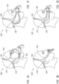
Figures 1A to 1D show non-limiting exemplary embodiments of headgear arrangements of the present disclosure in use in combination with a breathing apparatus 110. Theheadgears 100 are configured to be substantially inelastic and three-dimensional (3D) in structure. As used herein, a three-dimensional structure is one that does not lie in a single plane, but is shaped to extend in multiple planes. In other words, the three-dimensional structure is not flat. The illustratedheadgears 100 comprise a right side and a left side. Only the right side is illustrated in the Figures but the right and left sides are substantially identical. The right and left sides are formed as substantially two dimensional (2D) pieces, i.e., they are formed in a flat structure. The right and left sides each include atop strap 140, arear strap 150, afront strap 160, and a yoke orjunction portion 170. When thetop straps 140 and therear straps 150 of the right and left sides are joined together, a 3D bifurcated structure is formed. - The
top strap 140 is configured to extend upwardly from thejunction portion 170 at a location generally above each ear of the user and over the parietal or frontal region of a user's head. Therear straps 150 comprise an elongate member and are configured to extend rearward from thejunction portion 170 from a location generally above each ear of the user and around the occipital region of the user's head. Therear strap 150 is configured to be positioned at or near a central point or location on the rear of the user's head. Therear strap 150 is configured to directly or indirectly adjoin thejunction portion 170. Thefront strap 160 comprises elongate members that are configured to directly or indirectly adjoin thejunction portion 170 and extend forward across the user's temples towards their nose. In some configurations, thefront strap 160 is shorter than one or both of thetop strap 140 or therear strap 150. - In some configurations, the
junction portion 170 comprises a relatively triangular section that is configured to provide a lateral junction between the correspondingtop strap 140,rear strap 150 andfront strap 160. Each of the top, rear andfront straps junction portion 170 in a continuous manner such that the right and left sides of theheadgear 100 are formed as unitary pieces. The thickness and/or shape of thejunction portion 170 can be defined to restrict rotational movement about a lateral axis or axis extending in a thickness direction of thejunction portion 170 of the top, rear andfront straps -
Figure 2A illustrates thejunction portion 170 of theheadgear 100 without the top, rear and front straps attached. For the purpose of discussion, the following disclosure is focused on the forming of thejunction portion 170. However, the configuration and construction of thejunction portion 170 disclosed herein may be used to form other portions of theheadgear 100 such as the straps, alone or in combination with the junction portion. The following disclosure also focuses on forming thejunction portion 170 because the junction portion has a non-linear shape and geometry which makes thejunction portion 170 difficult to manufacture. As shown inFigure 2A , thejunction portion 170 comprises a substantially triangular profile region with multiple curved segment and truncated corners from which the top, rear and front straps extend. Thejunction portion 170 has a layered composition comprising aplastic core 240 surrounded by afirst textile casing 200 and asecond textile casing 200. The first and secondtextile casings 200 comprise layers of textile material. Thefirst textile casing 200 is configured to contact the user's head while thesecond textile casing 200 is configured to face away from the user's head, or vice versa. The first and secondtextile casings 200 may be made from the same or different textiles and can be configured to provide a soft and, in some embodiments, cushioned covering for thecore 240. However, in at least some preferred embodiments, the core 240 forms the primary structure of theheadgear 100 and thetextile casings 200 are utilized to provide theheadgear 100 with a softer texture, improved moisture wicking properties and/or increased friction with the user's face relative to a headgear having the core 240 but without thecasings 200. Such an arrangement is in contrast to headgear arrangements constructed primarily of an elastic or flexible material that utilize localized rigidizing structures. - In some configurations, the
core 240 comprises a relatively rectangular cross-section of a thermoform or thermoset plastic material that is configured to provide theheadgear 100 with the aforementioned 3D structure. Thecore 240 provides the foundation for the overall structure of theheadgear 100. The plastic composition of the core 240 offers the benefits of a resilient structure that is capable of maintaining a preformed shape while conforming somewhat to the individual cranial geometry of the user. The shape and geometry of the core 240 in combination with the material selection allows theheadgear 100 to be flexible in a horizontal direction across the user's face and relatively inflexible in a vertical direction across the user's face. This flexibility in one direction allows theheadgear 100 to conform to a user's head while providing rigidity in a direction that stabilizes and minimizes dislodging of the mask or seal on a user's face. - In some configurations, the first and second
textile casings 200 are configured to be permanently bonded to thecore 240 such that thecore 240 is completely encased and theheadgear 100 is formed from composite material. The first and secondtextile casings 200 are held together in close proximity by their bonds with thecore 240. As shown inFigure 2A , each of the first and secondtextile casings 200 have a folded-overedge 230 along their outer perimeters. As will be discussed in detail below, the ends of the first and secondtextile casings 200 are folded inward into and toward an inner cavity formed by the first and secondtextile casings 200. The first and secondtextile casings 200 contact each other at their folded-overedges 230. In some configurations, the first and secondtextile casings 200 do not directly contact each other at their folded-overedges 230. That is, the folded-overedges 230 can be separated from one another such that a portion of thecore 240 is left exposed. In other configurations, the folded-overedge 230 may be skewed towards one or other of the first and secondtextile casings 200. -
Figure 2B shows the components comprising one-half or one side of the junction portion 170 (i.e., an inward-facing portion or an outward-facing portion of the junction portion 170) prior to assembly and intra-moulding. As shown, thejunction portion 170 comprises atextile casing 200 and aplastic substrate 300. Accordingly, in the illustrated configuration, thejunction portion 170 is formed as an intra-moulded component using a pair oftextile casing 200 and a pair ofsubstrates 300. That is, in the illustrated configuration, thejunction portion 170 is formed by joining a pair ofsubstrates 300 that have atextile casing 200 attached to their outer surfaces. Further, thesubstrate 300 is configured to support and secure thetextile casing 200 within a mould tool before intra-moulding. That is, thesubstrate 300 forms a frame structure that thetextile casing 200 is wrapped over and secured to. Securing thetextile casings 200 to thesubstrates 300 prevents or inhibits thetextile casings 200 from moving out of position or alignment when the mould tool is closed. Further, securing thetextile casings 200 to thesubstrates 300 prevent or inhibits thetextile casings 200 from being pushed out of place by the pressure of the injected material during the intra-moulding process. Thetextile casing 200 and thesubstrate 300 have a substantially similar shape and geometry. In the illustrated configuration, thesubstrate 300 is centered or positioned within a center of thetextile casing 200 such that the outer edges of thesubstrate 300 are substantially equidistant from the outer edges of thetextile casing 200. - Headgear arrangements may be formed using an intra-moulding technique as disclosed in
U.S. Patent Application 14/856502 , which is herein incorporated by reference. "Intra-moulding" comprises forming a component as a plastic core and a textile casing as an integral structure by the application of molten plastic into the textile casing. A strap or any other component that has been "intra-moulded" is a component formed by the application of molten plastic into the textile casing. Throughout this specification, reference is made to "intra-moulding", processes, techniques, arrangements and components made by such moulding, processes and techniques. It is to be appreciated that all such references are general references to embodiments of the present disclosure and are not intended to be specifically limiting. -
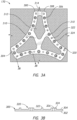
Figure 3A illustrates a top view of thesubstrate 300. The illustratedsubstrate 300 has a triangular shape havingcurved portions 306 connected to endportions 308. In some configurations, theend portions 308 serve as mounting points where the top, rear and front straps may be attached to, bonded to, or integrally formed with thesubstrate 300. Thesubstrate 300 is substantially flat and planar having anouter surface 302 and aninner surface 304. As will be discussed further below, theouter surface 302 faces thetextile casing 200 and theinner surface 304 faces an opposing and adjoiningsubstrate 300. Although thesubstrate 300 is illustrated as substantially flat and planar, it should be understood to one of ordinary skill in the art that thesubstrate 300 may have a contoured three-dimensional shape. Thesubstrate 300 is made from a substantially inelastic material, such as polypropylene or nylon, for example but without limitation. In embodiments where theheadgear 100 is expected be subjected to low loading forces, thesubstrate 300 may be made of other materials, such as, but not limited to, thermoplastic elastomers (TPE) or silicone. In some embodiments, thesubstrate 300 may have a degree of elasticity and one or both of the inner and/orouter textile casings 200 can be substantially inelastic. Further, in some configurations, thesubstrates 300 may differ in shape, geometry, material, and/or material properties. That is, the invention is not limited to substrates having identical features and characteristics. - The
substrate 300 forms a frame or skeleton structure for thejunction portion 170. Thesubstrate 300 hascrossbars 310 connected to each other and to the midpoints of thecurved portions 306. Thecrossbars 310 structurally connect thecurved portions 306 to strengthen thesubstrate 300 and prevent thesubstrate 300 from yielding due to forces applied by the top, rear and front straps. Further, thecrossbars 310 prevent thecurved portions 306 of thesubstrate 300 from collapsing and/or distorting when thetextile casing 200 is wrapped over thesubstrate 300. Thesubstrate 300 hasapertures 312 defined by thecurved portions 306 and thecrossbars 310. Theapertures 312 allow thesubstrate 300 to be thinner and thus the headgear to be lighter and less bulky while thecrossbars 310 provide strength and stability to thecurved portions 306. Theapertures 312 also provide gaps for core material to fill during the intra-moulding process. The core material may be injected into thejunction portion 170 through agate 314 positioned on anend portion 308. Thegate 314 is recessed into thesubstrate 300 and extends toward theapertures 312. - The
substrate 300 has a plurality of textile retaining features 320 positioned along thecurved portions 306 and endportions 308. As will be discussed in greater detail below, the textile retaining features 320 on thesubstrate 300 engage the substrate retaining features 220 on thetextile casing 200 to secure thetextile casing 200 to thesubstrate 300. As shown inFigure 3B , the textile retaining features 320 protrude from theinner surface 304 of thesubstrate 300 and comprise a plurality ofposts 322 andsockets 324 in alternating arrangement that are equidistantly spaced along thecurved portions 306 and theend portions 308. Theposts 322 andsockets 324 may have their centers aligned on a centerline and the centerline may be positioned along a median of thecurved portions 306 and end portions 308 (i.e., equidistant between the edges of thecurved portions 306 and end portions 308). It should be understood to one of ordinary skill in the art that theposts 322 andsockets 324 are not limited to having their centers aligned on a centerline and may have their centers positioned at varying locations on thecurved portions 306 connected to endportions 308. - The
posts 322 andsockets 324 are cylindrical in shape and circular in cross-section. Theposts 322 are illustrated as solid cylindrical columns that protrude perpendicularly outward from theinner surface 304 of thesubstrate 300. Thesockets 324 are illustrated as hollow cylindrical tubes that also protrude perpendicularly outward from theinner surface 304 of thesubstrate 300. Thesockets 324 have aninterior hole 326 that extends through thesocket 324 and, in some configurations, also through thesubstrate 300. In other words, in some configurations, theinterior hole 326 does not penetrate or extend through theentire substrate 300. Theposts 322 have an outer diameter that is similar to the diameter of the interior hole 326 (i.e., the inner diameter of the socket 324). As such, thepost 322 andsocket 324 may have a snap fit or interference fit to retain thepost 322 in thesocket 324 when connected. The thickness of the walls of the socket 324 (i.e., the difference between the diameter of theinterior hole 326 and outer diameter of the socket 324) may be similar to a thickness of thesubstrate 300. - In some configurations, the
sockets 324 may comprise only ofholes 326 that extend through the thickness of thesubstrate 300. That is, thesockets 324 haveholes 326 that are recessed into theinner surface 304 of thesubstrate 300 but do not have a hollow cylindrical tube that protrudes perpendicularly outward from theinner surface 304 of thesubstrate 300. Such an arrangement may provide a thinner headgear, as the pair ofsubstrates 300 will only be separated by the thickness of thetextile casings 200. A thinner headgear may be desirable for aesthetics and user comfort and perception. - The
junction portion 170 is formed by connecting together a pair ofsubstrates 300 prior to intra-moulding. That is, when connecting asubstrate 300 to an adjoiningsubstrate 300, theposts 322 of thesubstrate 300 are inserted into and engage thesockets 324 of the adjoiningsubstrate 300. Accordingly, the adjoiningsubstrate 300 also has a plurality of alternatingposts 322 andsockets 324 that are equidistantly spaced along thecurved portions 306 and theend portions 308. However, in the illustrated arrangement, the order of theposts 322 andsockets 324 on the adjoiningsubstrate 300 may be inversed, reversed or offset such that asocket 324 is positioned at a position on the adjoiningsubstrate 300 to receive apost 322 of the substrate 300 (i.e., in contrast to having two opposingposts 322 or two opposing sockets 324). Put another way, the adjoiningsubstrate 300 may have an opposite pattern ofposts 322 andsockets 324 such that theposts 322 of the adjoiningsubstrate 300 align with thesockets 324 of the other substrate, and vice versa. In some configurations (not shown), onesubstrate 300 may haveonly posts 322 while the adjoiningsubstrate 300 has onlysockets 324. -
Figure 4 illustrates thetextile casing 200 with asubstrate 300 overlaid. Thetextile casing 300 can be made of any suitable textile, such as microfiber towelling, suede, or unbroken loop (UBL). Thetextile casing 200 has substantially the same shape as thesubstrate 300 but thetextile casing 200 is larger (i.e., longer, wider) such that the outer edges of thetextile casing 200 extend beyond the outer edges of thesubstrate 300. That is, in the illustrated configuration, thesubstrate 300 is larger in all radial directions than thesubstrate 300. As illustrated, anoverhanging region 202 is defined as the portion of thetextile casing 200 that extends beyond the outer perimeter or radial edges of thecurved portions 306 and theend portions 308 of thesubstrate 300 when thesubstrate 300 is overlaid over the center of thetextile casing 200 in an aligned orientation. That is, the overhangingregion 202 is an outer portion of thetextile casing 200 that is not overlapped by thesubstrate 300. As shown inFigures 5A and 5B and discussed further below, the overhangingregion 202 of thetextile casing 200 is configured to be folded over thesubstrate 300. Therefore, the overhangingregion 202 may extend a distance beyond the outer edges of thesubstrate 300 that is greater than or equal to a combined distance comprising the thickness of thesubstrate 300 and the width of thecurved portions 306 or theend portions 308. - The
textile casing 200 has substrate retaining features 220 positioned on theoverhanging region 202 between the outer edges of thetextile casing 200 and the outer edges of thesubstrate 300. The substrate retaining features 220 of thetextile casing 200 are configured to engage the textile retaining features 320 of thesubstrate 300. In the illustrated configuration, the substrate retaining features 220 include a plurality of alternatingpost holes 222 andsocket holes 224 that are equidistantly spaced within the overhangingregion 202. The post holes 222 andsocket holes 224 extend through the thickness of thetextile casing 200. The post holes 222 andsocket holes 224 may be formed by cutting or punching through thetextile casing 200. - As shown in
Figures 5A and 5B , the plurality of alternatingpost holes 222 andsocket holes 224 of thetextile casing 200 are configured to receive the plurality of alternatingposts 322 andsockets 324 of thesubstrate 300 when the overhangingregion 202 of thetextile casing 200 is folded over thesubstrate 300. That is, theposts 322 andsockets 324 are inserted and retained in the post holes 222 andsocket holes 224 when the overhangingregion 202 is folded over thesubstrate 300. Accordingly, the post holes 222 andsocket holes 224 have a corresponding size, shape, order and arrangement as theposts 322 andsockets 324. More specifically, in the illustrated arrangement, the post holes 222 andsocket holes 224 are circular which corresponds to the circular cross-sections of theposts 322 andsockets 324. The post holes 222 have a diameter equal to or larger than the outer diameter of thepost 322. Similarly, the socket holes 224 have a diameter equal to or larger than the outer diameter of thesocket 324. Providing post andsocket holes posts 322 andsockets 324 may prevent theposts 322 andsockets 324 from retaining theoverhanging region 202 of thetextile casing 200 attached to thesubstrate 300. In some configurations, when thetextile casing 200 is formed from an elastic material, the post holes 222 andsocket holes 224 may have diameters that are smaller than the diameters of theposts 322 andsockets 324 to provide a friction or interference fit with thesubstrate 300. The post holes 222 andsocket holes 224 are positioned a distance from the outer edge of thesubstrate 300 within the overhangingportion 202 such that thetextile casing 200 is tautly wrapped around thesubstrate 300 when the post holes 222 andsocket holes 224 are connected to theposts 322 andsockets 324. More specifically, in some configurations, the post holes 222 andsocket holes 224 are positioned a distance from the outer edge of thesubstrate 300 that is equal to a combined distance comprising the thickness of thesubstrate 300 and a distance between the outer edge of thesubstrate 300 and the centerline that includes the centers of theposts 322 andsockets 324. -
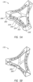
Figures 6A to 6C illustrate asleeve 400 of thejunction portion 170 that is formed by connecting or interlocking the pair ofsubstrates 300. That is, a pair oftextile casings 200 is each attached to asubstrate 300 via the post andsocket holes posts 322 andsockets 324. Then, thesubstrates 300 are attached to each other via theposts 322 andsockets 324 to form thesleeve 400. More specifically, theposts 322 are inserted into and connected to thesockets 324 when connecting onesubstrate 300 with an adjoiningsubstrate 300 to assemble thejunction portion 170, thereby forming asleeve 400. That is, theposts 322 are positioned in theinterior hole 326 of thesocket 324 to connect thesubstrates 300. The snap fit or interference fit between theposts 322 andsockets 324 maintain theposts 322 connected to thesockets 324 and keep thesubstrates 300 from separating.Figure 6C illustrates theposts 322 andsockets 324 of a pair ofsubstrates 300 in alignment (withouttextile casings 200 attached) prior to connecting theposts 322 andsockets 324. - The
sleeve 400 of thejunction portion 170 is inserted into a cavity of an injection moulding tool (not shown) and the injection moulding tool is closed. When thesleeve 400 is positioned in the mould tool, thetextile casings 200 are secured onto thesubstrate 300 such that thetextile casings 200 are prevented and inhibited from moving out of alignment relative to the mould tool and from being pushed out of alignment by the pressure of the injected plastic material. As such, thesleeve 400 allows the plastic core material to be injected into, and to thereby fill, the inside of thesleeve 400. The folded-overedge 230 of thetextile casing 200 is permanently fused inside the plastic core material to provide a tidy, smooth and durable edge finish. When thesleeve 400 is injected with the plastic core material, the injected plastic flows through thesleeve 400, fuses with thesubstrate 300 and bonds with thetextile casing 200. The plastic core material can be the same as the material of thesubstrate 300 such that the plastic core material and thesubstrate 300 chemically bond resulting in thejunction portion 170 having a uniform core. Alternatively, different materials may be used for thesubstrate 300 and the plastic core material. In some embodiments the plastic core material may be softer or more elastic than thesubstrate 300. This may provide additional flexibility and elasticity for improving fitment of the headgear, and may also improve comfort for the user. -
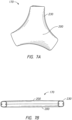
Figures 7A and 7B show thejunction portion 170 after being injected with plastic core material and allowed to cool. As shown, the folding over of thetextile casing 200 over thesubstrate 300 produces an edge finish that is both aesthetically pleasing and comfortable against a user's head. That is, with the folded-overedges 230 of thetextile casing 200 provide a smoother edge that is comfortable against the user's skin. In contrast, ajunction portion 170 formed having crimped edges of the textile casings that extend radially outward from the junction portion 170 (i.e., as opposed to being folded inward into the junction portion 170) may have an edge finish that is untidy in appearance with sharp edges if injected plastic core material protrudes from the edges of the textile casings (i.e., flash). However, folding theoverhanging region 202 of thetextile casing 200 over and onto thesubstrate 300 provides thejunction portion 170 with a smooth contoured edge that follows the shape of thesubstrate 300. - In some embodiments, only one
substrate 300 may have atextile casing 200 such that only one side of thejunction portion 170 has a textile casing. Similarly, the first and secondtextile casings 200 may be made from differing materials. This may provide theheadgear 100 with varied physical properties in different regions of theheadgear 100. Further the height of theposts 322 andsockets 324 may vary according to the thickness of thetextile casing 200. The heights of theposts 322 may also be different from the heights of thesockets 324. Similarly, the number or quantity ofposts 322 andsockets 324 and the spacing between theposts 322 andsockets 324 may vary according to the size and shape of thejunction portion 170 and/or the flexibility of thetextile casing 200. Further, theposts 322 andsockets 324 are not limited to having circular cross-sectional shapes. In some configurations, theposts 322 andsockets 324 may have a variety of cross-sectional shapes such as, for example, polygonal and/or curved elongate shapes. Further, theposts 322 andsockets 324 may have cross-sectional shapes that are configured to reduce the formation of wrinkles or creases of thetextile casing 200 when thetextile casing 200 is folded over a curved portion of thesubstrate 300. Reducing wrinkling or creasing provides a cleaner edge finish that is more aesthetically pleasing and comfortable against a user's head. Further, it should be understood to one of ordinary skill in the art that the above described intra-moulding arrangement is not limited to the forming of junction portions of the headgear. The above described intra-moulding arrangement may be used to form any portion of the headgear to improve manufacturing reliability and provide an edge finish that is both aesthetically pleasing and comfortable against a user's head. -
Figure 8 illustrates a reversible substrateconfiguration having posts 322 andsockets 324 that alternate along each edge of thesubstrate 300 such that only a single substrate configuration is required. That is, thesubstrates 300 are reversible such that a pair ofsubstrates 300 can be joined or interlocked together when theinner surfaces 302 of eachsubstrate 300 face each other. Theposts 322 andsockets 324 are arranged such that eachsubstrate 300 of an adjoining substrate pair is identical. More specifically, theposts 322 andsockets 324 alternate along each edge of thesubstrate 300 and eachpost 322 opposes asocket 324 on either side of a central plane marked as A-A inFigure 8 . Thetextile casing 200 haspost holes 222 andsocket holes 224 that correspond with theposts 322 andsockets 324. This arrangement allows a pair ofidentical textile casings 200 andsubstrates 300 to be connected together which minimises components and manufacturing costs. -
Figure 9 illustrates an alternative retaining features configuration having asubstrate 300 with retaininghooks 352 that are inserted through acorresponding hole 252 on theoverhanging region 202 of thetextile casing 200 to retain and lock thetextile casing 200 onto thesubstrate 300. The retaining hooks 352 extend toward a centre of thesubstrate 300. Thecrossbars 310 are positioned on each side of the retaining hooks 352 and extend to connect adjacentcurved portions 306. In this embodiment there are no retaining features such as posts and sockets to secure two substrates together which allow thesubstrate 300 to be thinner and narrower. The retaining hooks 352 sit withinapertures 312 such that the retaining hooks are flush with thesubstrate 300 which reduces the overall thickness of thesubstrate 300 and the headgear. That is, the curved andend portions substrates 300 may be placed on top of each other (i.e., back-to-back with theinner surfaces 302 facing each other) within the cavity of the injection moulding tool to form a sleeve within which plastic core material is injected. In alternative embodiments, the textile casing may be attached to the substrate by any other appropriate means including adhesives or welding, rather than a mechanical bond. -
Figures 10A and 10B illustrates an alternative substrate arrangement for forming ajunction portion 500 without having retaining features formed on the substrate. Thejunction portion 500 includes atextile casing 510, asubstrate 520 and aninsert 530. Similar to the substrate arrangements described above, thesubstrate 520 provides a frame structure that thetextile casing 200 is wrapped over and secured onto. Also, thesubstrate 520 has anaperture 522 defined by anouter frame 524. However, in contrast to latching theoverhanging region 512 of thetextile casing 510 onto posts and sockets, the overhangingregion 512 is folded over the edges of theouter frame 524 such that the overhangingregion 512 extends into theaperture 522. Theinsert 530 is then inserted into theaperture 522 so that the edges of theoverhanging region 512 are sandwiched between theinsert 530 and theouter frame 524, as shown inFigure 10B . Accordingly, a pair of textile coveredsubstrates 520 may be placed be placed on top of each other (i.e., back-to-back with theinserts 530 facing each other) within the cavity of the injection moulding tool to form a sleeve within which plastic core material is injected. -
Figure 10C illustrates a substrate arrangement having aninsert 630 covered by atextile casing 640 for forming a textile-coveredjunction portion 600 using asingle substrate 620 for providing athinner junction portion 600 and headgear. Theinsert 630 is pushed into the aperture 622 defined by theouter frame 624 of thesubstrate 620. However, in contrast to thejunction portion 500 inFigures 10A-B , the edges of theoverhanging region 612 and the edges of thetextile casing 640 are sandwiched between theinsert 630 and theouter frame 624. Accordingly, thejunction portion 600 may be entirely covered in textile material without utilizing a pair ofsubstrates 620 which provides a thinner overall headgear. A thinner headgear is beneficial to user comfort and the desirability of the product. Further, in contrast to a junction formed using a pair of substrates, the seam betweentextile casings junction portion 600, which provides a softer and more aesthetically pleasing appearance to the junction. In some configurations, different textiles may be used to cover thesubstrate 620 and theinsert 630. -
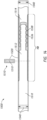
Figure 11 illustrates a substrate arrangement for forming anelongate headgear strap 700. In contrast to thejunction portion 170 inFigures 2A-7B , thestrap 700 comprises asingle substrate 710 that is wrapped in asingle textile casing 730. Thesubstrate 710 is folded over onto itself to form a sleeve within which plastic core material is injected. Thesubstrate 710 includes a pair ofedge segments 712 that extend and span the length of thestrap 700. Theedge segments 712 are connected by a plurality ofcrossbars 714 that link theedge segments 712 and provide stability and structure between theedge segments 712. Thecrossbars 714 may be thinner in thickness than theedge segments 712 such that thecrossbars 714 are more flexible to allow thesubstrate 710 to be folded over onto itself. Thecrossbars 714 may be equidistantly spaced along agap 716 that separates theedge segments 712. - The
edge segments 712 havesockets 722 andposts 724 that are equidistantly spaced along theedge segments 712. To allow theedge segments 712 to be folded over onto itself and connected, the order of theposts 722 andsockets 724 on one of theedge segments 712 is inversed, reversed or offset such that asocket 724 on oneedge segment 712 is positioned adjacent to apost 722 on the adjoining segment 712 (i.e., in contrast to having two opposingposts 722 or two opposing sockets 724). Put another way, the adjoiningedge segment 712 may have an opposite pattern ofposts 722 andsockets 724 such that theposts 722 of the adjoiningedge segment 712 align with thesockets 724 of the other substrate, and vice versa. In some configurations (not shown), oneedge segment 712 may haveonly posts 722 while the adjoiningedge segment 712 has onlysockets 724. - The
textile casing 730 has a corresponding shape as thesubstrate 710. Thetextile casing 730 includes anoverhanging region 736 that extends beyond the edges of thesubstrate 710 and is not overlapped by thesubstrate 710. As illustrated, thesubstrate 710 has a substrate width W1 that is measured perpendicular to the lengthwise direction of thestrap 700. Thetextile casing 730 has a textile casing width W2 this is also measure perpendicular to the lengthwise direction of thestrap 700. The textile casing width W2 is greater than the substrate width W1. The remainder ofnon-overlapping textile casing 730 is illustrated as overhangingregions 736. Thesubstrate 710 is positioned in an overlapping orientation with thetextile casing 730 such that overhangingregions 736 are positioned on both sides of thesubstrate 710. The overhangingregion 736 of thetextile casing 730 includes post holes 732 andsocket holes 734 through which thesockets 722 andposts 724 are positioned therein to retain and lock thetextile casing 730 onto thesubstrate 710 when the overhangingregions 736 are folded over thesubstrate 710. When thetextile casing 730 is attached to thesubstrate 710, thesubstrate 710 is folded over onto itself and theedge segments 712 are connected via theposts 722 andsockets 724 which forms a sleeve within which plastic core material is injected. -
Figures 12A to 12F illustrates an alternative substrate arrangement for forming anelongate headgear strap 800. Similar to thejunction portion 170 inFigures 2A-7B , thestrap 800 comprises a pair ofsubstrates 810 that extend and span the length of thestrap 800 and are wrapped in atextile casing 830, as shown inFigure 12B . Thesegments 812 are connected by a plurality ofcrossbars 814 that link theedge segments 812 and provide stability and structure between theedge segments 812. In contrast to thesubstrate 710 inFigure 11 , thecrossbars 814 are substantially rigid. As illustrated inFigure 12C , theedge segments 812 may have a thinner thickness than thecrossbars 814 to provide longitudinal strength along the length of thestrap 800. Alternatively, theedge segments 812 and thecrossbars 814 may be identical in thickness, as shown inFigure 12D . - The
edge segments 812 havesockets 822 andposts 824 that are spaced along theedge segments 812. In contrast to the arrangement of sockets and posts 122, 124 inFigures 2A-7B , the sockets andposts segments 812. The arrangement of sockets andposts socket 824 on oneedge segment 812 is positioned adjacent to apost 822 on the adjoiningsegment 812. As a result, in some configurations, thesubstrate 810 may be modular such that a pair ofidentical substrates 810 may be connected together which minimises components and manufacturing costs. It should be understood to one of ordinary skill in the art that thestrap 800 is not limited to the illustrated positioning, order and/or arrangement of sockets andposts posts - The
textile casing 830 has a corresponding shape as thesubstrate 810 and includes anoverhanging region 836 that extends beyond the edges of thesubstrate 810 and is not overlapped by thesubstrate 810. The overhangingregion 836 of thetextile casing 830 includes post holes 832 and socket holes 834 through which thesockets 822 andposts 824 are positioned therein to retain thetextile casing 830 onto thesubstrate 810 when the overhangingregions 836 are folded over thesubstrate 810 and lock thetextile casing 830 when thesubstrates 810 are connected. When thetextile casing 830 is attached to thesubstrate 810, a pair ofsubstrates 810 is interlocked by inserting theposts 822 into thesockets 824, as shown inFigure 12E . Accordingly, the interlockingsubstrates 810 form a sleeve within which plastic core material is injected.Figure 12F illustrates a cross-section of thestrap 800 after the plastic core material is injected and intra-moulding is completed. As shown, thesubstrate 810 and the plastic core material form auniform core 840. That is, thesubstrates 810 and the plastic core material chemically bond and combine to form theuniform core 840. -
Figure 13 illustrates a substrate arrangement having one or more headgear straps and/or connectors that are integrally formed with ajunction portion 1170. Thejunction portion 1170 comprises a pair ofsubstrates 1300 that are wrapped intextile casings 1200. Similar to thejunction portion 170 inFigures 2A-7B , the pair of textile-wrappedsubstrates 1300 is connected to form a sleeve within which plastic core material is injected. Thejunction portion 1170 is formed by connecting the pair of textile-wrappedsubstrate 1300 wrapped. However, in contrast, thesubstrate 1300 includes astrap portion 1316 extending from one end of thesubstrate 1300. Thestrap portion 1316 includesposts 1322 andsockets 1324 that are equidistantly spaced along the length of thestrap portion 1316. Similarly, thetextile casing 1200 has a corresponding shape as thesubstrate 1300 to accommodate thestrap portion 1316 such that thetextile casing 1200 may be wrapped around thestrap portion 1316. Thetextile casing 1200 includes anoverhanging region 1202 that extends beyond and is not overlapped by thesubstrate 1300. Thestrap portion 1316 includespost holes 1222 andsocket holes 1224 through which theposts 1322 andsockets 1324 are positioned therein to retain theoverhanging region 1202 of thetextile casing 1200 when thetextile casing 1200 is folded over thesubstrate 1300. - The
substrate 1300 includes male andfemale connectors portions 1308 of thesubstrate 1300. The male andfemale connectors female connectors substrate 1300. Alternatively, the male andfemale connectors male connector 1332 includesbumps 1336 that protrude outward from themale connector 1332 and thefemale connector 1334 includesnotches 1338 notches recessed into thefemale connector 1334 to provide a push-fit or snap-fit connection with opposing male andfemale connectors 1332, 1334 (e.g., male and female connectors on the mask frame, a separate strap, the opposite junction, etc.). That is, themale connector 1332 is connected to thefemale connector 1334 by inserting themale connector 1332 into thefemale connector 1334 such that thebumps 1336 are positioned within thenotches 1338. Themale connector 1332 extends beyond thetextile casing 1200 such that thetextile casing 1200 does not obstruct insertion of themale connector 1332 into thefemale connector 1334. Similarly, the opening of thefemale connector 1334 may extend from theend portion 1308 of thesubstrate 1300 and be aligned with the edge of thetextile casing 1200 such that thetextile casing 1200 does not obstruct insertion of themale connector 1332 into thefemale connector 1334. It should be understood to one of ordinary skill in the art that thejunction portion 1170 is not limited to male and female snap-fit connectors and may include alternative connection arrangements. It should be understood to one of ordinary skill in the art that the male andfemale connectors -
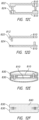
Figure 14 illustrates a substrate configuration for astrap 1500 having an integrally formed internal length adjustment mechanism 1502. The length adjustment mechanism 1502 may be integrally formed internally within a headgear strap which provides a strap and adjustment mechanism arrangement with a tidy aesthetic appearance. Similar to the above configurations, the length adjustment mechanism includessubstrates 1510 that are wrapped intextile casings 1520. Thetextile casings 1520 may be attached to thesubstrates 1510 using any of the features or combination of features described above such that the ends of thetextile casings 1520 are folded into and bonded with the core, as illustrated. Similarly, thesubstrates 1510 may include a single substrate or an interlocking pair of substrates, as previously described herein. - The
substrates 1510 have amale substrate portion 1512 and afemale substrate portion 1514 that are integrally formed into thesubstrate 1510. Themale substrate portion 1512 is engaged with thefemale substrate portion 1514 to provide length adjustability to thestrap 1500. Themale substrate portion 1512 hasbumps 1536 that protrude outward from themale substrate portion 1512 in a direction perpendicular to a lengthwise direction of thestrap 1500 and towards thefemale substrate portion 1514. Thefemale substrate portion 1514 hasnotches 1538 recessed into thefemale substrate portion 1514 and having a shape that corresponds to the shape of thebumps 1536. Thebumps 1536 engage thenotches 1538 via a snap-fit to allow the adjustment mechanism 1502 to provide discrete length adjustment of thestrap 1500. Thesubstrates 1510 are pre-molded with themale substrate portion 1512 and afemale substrate portion 1514. - As illustrated in the cross-sectional views, the
textile casing 1520 surrounding portions of thestrap 1500 containing the length adjustment mechanism 1502 is not bonded to thesubstrate 1510, which is designated inFigure 14 as a non-bonded region NB. However, portions oftextile casing 1520 outside of the non-bonded region NB are bonded to thesubstrate 1510 such that thestrap 1500 has auniform core 1540, as shown in the cutaway cross-sectional view. Thetextile casing 1520 is not bonded within the non-bonded region NB such that thetextile casing 1520 is free to expand and contract when the length adjustment mechanism 1502 is adjusted (i.e., the relative positions of themale substrate portion 1512 and afemale substrate portion 1514 changes such that thestrap 1500 increases or decreases in length). Accordingly, thetextile casing 1520 may be formed from a stretchable elastic material such as Breath-o-prene™. -
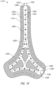
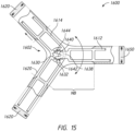
Figure 15 illustrates a substrate configuration for ajunction portion 1600 having an integrally formed internalangular adjustment mechanism 1602. Theangular adjustment mechanism 1602 allows the angle between headgear straps to be adjustable which provides improved fitment for a range of user head shapes and sizes. Similar to the above configurations, the angular adjustment mechanism includes substrates 1610 that are wrapped intextile casings 1620. Further, thetextile casing 1620 surrounding portions of thejunction portion 1600 containing theangular adjustment mechanism 1602 are not bonded to the substrate 1610, which are designated inFigure 15 as a non-bonded regions NB. Similarly, portions of thetextile casings 1620 outside of the non-bonded region NB are bonded to the substrate 1610 such that thejunction portion 1600 has auniform core 1650, as shown in the cutaway cross-sectional views. - The substrates 1610 have a
male substrate portion 1612 and afemale substrate portion 1614 that are integrally formed into the substrate 1610. Themale substrate portion 1612 is engaged with thefemale substrate portion 1614 to provide rotational adjustability to thejunction portion 1600. Thefemale substrate portion 1612 has aninternal spur gear 1630 having a plurality ofteeth 1632. Themale substrate portion 1612 has apinion gear 1640 positioned on anarm 1638 that extends from an end portion ofmale substrate portion 1612. Thearm 1638 and thepinion gear 1640 are integrally formed with themale substrate portion 1612. Thepinion gear 1640 has a plurality ofteeth 1642 arranged around on an outer circumference of thepinion gear 1640. Theteeth 1642 of thepinion gear 1640 are engaged with theteeth 1632 of theinternal spur gear 1630 to maintain the relative rotational position between themale substrate portion 1612 and thefemale substrate portion 1614. Thepinion gear 1640 is forked, having a centrally located split orfork 1644 that is parallel to the length of thearm 1638. Thefork 1644 allows the two sides of thepinion gear 1640 to flex towards each other, which reduces the diameter of thepinion gear 1640 to allow theteeth internal spur gear 1630 and thepinion gear 1640 to disengage. While disengaged, theteeth male substrate portion 1612 to be rotated relative to thefemale substrate portion 1614 such that the angle between headgear straps can be adjusted which provides improved fitment for a range of user head shapes and sizes. - Unless the context clearly requires otherwise, throughout the description and the claims, the words "comprise", "comprising", and the like, are to be construed in an inclusive sense as opposed to an exclusive or exhaustive sense, that is to say, in the sense of "including, but not limited to". Conditional language used herein, such as, among others, "can," "could," "might," "may," "e.g.," and the like, unless specifically stated otherwise, or otherwise understood within the context as used, is generally intended to convey that certain embodiments include, while other embodiments do not include, certain features, elements and/or states. Thus, such conditional language is not generally intended to imply that features, elements and/or states are in any way required for one or more embodiments or that one or more embodiments necessarily include logic for deciding, with or without author input or prompting, whether these features, elements and/or states are included or are to be performed in any particular embodiment.
- The term "plurality" refers to two or more of an item. Recitations of quantities, dimensions, sizes, formulations, parameters, shapes and other characteristics should be construed as if the term "about" or "approximately" precedes the quantity, dimension, size, formulation, parameter, shape or other characteristic. The terms "about" or "approximately" mean that quantities, dimensions, sizes, formulations, parameters, shapes and other characteristics need not be exact, but may be approximated and/or larger or smaller, as desired, reflecting acceptable tolerances, conversion factors, rounding off, measurement error and the like and other factors known to those of skill in the art. Recitations of quantities, dimensions, sizes, formulations, parameters, shapes and other characteristics should also be construed as if the term "substantially" precedes the quantity, dimension, size, formulation, parameter, shape or other characteristic. The term "substantially" means that the recited characteristic, parameter, or value need not be achieved exactly, but that deviations or variations, including for example, tolerances, measurement error, measurement accuracy limitations and other factors known to those of skill in the art, may occur in amounts that do not preclude the effect the characteristic was intended to provide.
- Numerical data may be expressed or presented herein in a range format. It is to be understood that such a range format is used merely for convenience and brevity and thus should be interpreted flexibly to include not only the numerical values explicitly recited as the limits of the range, but also interpreted to include all of the individual numerical values or sub-ranges encompassed within that range as if each numerical value and sub-range is explicitly recited. As an illustration, a numerical range of "1 to 5" should be interpreted to include not only the explicitly recited values of about 1 to about 5, but should also be interpreted to also include individual values and sub-ranges within the indicated range. Thus, included in this numerical range are individual values such as 2, 3 and 4 and sub-ranges such as "1 to 3," "2 to 4" and "3 to 5," etc. This same principle applies to ranges reciting only one numerical value (e.g., "greater than 1") and should apply regardless of the breadth of the range or the characteristics being described.
- A plurality of items may be presented in a common list for convenience. However, these lists should be construed as though each member of the list is individually identified as a separate and unique member. Thus, no individual member of such list should be construed as a de facto equivalent of any other member of the same list solely based on their presentation in a common group without indications to the contrary. Furthermore, where the terms "and" and "or" are used in conjunction with a list of items, they are to be interpreted broadly, in that any one or more of the listed items may be used alone or in combination with other listed items. The term "alternatively" refers to selection of one of two or more alternatives, and is not intended to limit the selection to only those listed alternatives or to only one of the listed alternatives at a time, unless the context clearly indicates otherwise.
- Reference to any prior art in this specification is not, and should not be taken as, an acknowledgement or any form of suggestion that that prior art forms part of the common general knowledge in the field of endeavour in any country in the world.
- Where, in the foregoing description reference has been made to integers or components having known equivalents thereof, those integers are herein incorporated as if individually set forth.
- The invention may also be said broadly to consist in the parts, elements and features referred to or indicated in the specification of the application, individually or collectively, in any or all combinations of two or more of said parts, elements or features.
- It should be noted that various changes and modifications to the presently preferred embodiments described herein will be apparent to those skilled in the art. Such changes and modifications may be made without departing from the spirit and scope of the invention and without diminishing its attendant advantages. For instance, various components may be repositioned as desired. It is therefore intended that such changes and modifications be included within the scope of the invention. Moreover, not all of the features, aspects and advantages are necessarily required to practice the present invention. Accordingly, the scope of the present invention is intended to be defined only by the claims that follow.
-
- 1. A headgear strap for a headgear assembly, comprising:
- a first substrate;
- a second substrate attached to the first substrate;
- a first textile casing attached to the first substrate;
- a second textile casing attached to the second substrate; and
- an intra-moulded core positioned between the first and second textile casings,
- wherein the first and second substrates, the first and second textile casings and the intra-moulded core are formed as an integral structure by the application of a molten plastic material between the first and second textile casings.
- 2. The headgear strap of Clause 1, wherein the first textile casing covers an inwardly-facing surface of the headgear assembly and the second textile casing covers an outwardly-facing the surface of the headgear assembly.
- 3. The headgear strap of Clauses 1 or 2, wherein the ends of the first and second textile casing are positioned between the first and second substrates.
- 4. The headgear strap of any one of Clauses 1-3, wherein each of the first and second substrates include a first retaining structure, and each of the first and second textile casings include a second retaining structure, wherein the first and second retaining features are configured to engage each other to attach the first textile casing onto the first substrate and the second textile casing onto the second substrate.
- 5. The headgear strap of Clause 4, wherein the first retaining structure of the first substrate engages the first retaining structure of the second substrate to connect the first and second substrates.
- 6. The headgear strap of Clauses 4 or 5, wherein the first retaining structure includes a post protruding outward from a surface of at least one of the first and second substrates, and a socket positioned on at least an other of the first and second substrates, the socket having an inner hole, wherein the post is positioned within the inner hole to connect the first and second substrates.
- 7. The headgear strap of Clause 6, wherein the socket protrudes outward from a surface of the other of the first and second substrates.
- 8. The headgear strap of Clauses 6 or 7, wherein the second retaining structure includes at least one hole extending through each of the first and second textile casings, wherein at least one of the post and the socket engages the hole to attach the first textile casing on the first substrate and the second textile casing on the second substrate.
- 9. The headgear strap of any one of Clauses 4-8, wherein the second retaining structure is positioned on portions of the first and second textile casing that are positioned between the first and second substrates.
- 10. The headgear strap of any one of Clauses 1-9, further comprising:
a strap connector preformed in at least one of the first and second substrates. - 11. The headgear strap of any one of Clauses 1-10, further comprising:
a length adjustment mechanism preformed in at least one of the first and second substrates. - 12. The headgear strap of any one of Clauses 1-11, further comprising:
an angular adjustment mechanism preformed in at least one of the first and second substrates. - 13. The headgear strap of any one of Clauses 1-12, wherein at least one of the first and second substrates includes a gate.
- 14. The headgear strap of any one of Clauses 1-13, wherein the first and second substrates are identical.
- 15. The headgear strap of any one of Clauses 1-14, wherein the intra-moulded core comprises an injection moulded plastic material that is injected between the first and second textile casings.
- 16. A headgear strap assembly comprising:
- a substrate having an outer surface and an inner surface that is opposite the outer surface; and
- a textile casing overlaid onto the outer surface of the substrate,
- wherein a width of the textile casing is greater than a width of the substrate.
- 17. The headgear strap assembly of Clause 16, wherein the textile casing includes an overhanging portion that extends beyond edges of the outer surface of the substrate, and the overhanging portion is configured to be folded over the edges onto the inner surface of the substrate.
- 18. The headgear strap assembly of Clauses 16 or 17, wherein the substrate includes a first retaining structure, and the textile casing includes a second retaining structure, wherein the first and second retaining features are configured to engage each other to attach the textile casing to the substrate.
- 19. The headgear strap assembly of Clause 18, wherein the first retaining structure includes a post protruding outward from the inner surface of the substrate.
- 20. The headgear strap assembly of Clauses 18 or 19, wherein the first retaining structure includes a socket protruding outward from the inner surface of the substrate, the socket having an inner hole extending through the socket.
- 21. The headgear strap assembly of Clauses 19 or 20, wherein the second retaining structure includes at least one hole extending through the textile casing, wherein at least one of the post and the socket engages the hole to attach the textile casing onto the substrate.
- 22. The headgear strap assembly of any one of Clauses 18-20, wherein the second retaining structure is positioned on the overhanging portion of the textile casing.
- 23. A method for forming a headgear assembly for a respiratory interface, comprising:
- securing textile casings onto an outer portion of each of a pair of substrates;
- connecting the pair of substrates along an inner portion of each of the pair of substrates;
- positioning the pair of substrates within a moulding tool;
- injecting molten plastic material between the pair of substrates; and
- allowing the molten plastic material to solidify to form a plastic core between the textile casings.
- 24. The method of Clause 23, wherein securing the textile casing includes folding the textile casing over ends of each of the pair of substrates such that ends of the textile casing are positioned between the pair of substrates.
- 25. The method of Clauses 23 or 24, wherein securing the textile casing includes fastening the ends of the textile casing to the inner portion of each of the pair of substrates.
- 26. The method of any one of Clauses 23-25, wherein connecting the pair of substrates includes interlocking the inner portions of the pair of substrates.
- 27. The method of any one of Clauses 23-26, wherein the pair of substrates are preformed unitarily as an integral structure.
- 28. The method of any one of Clauses 23-27, wherein the pair of substrates and molten plastic material chemically bond to provide a uniform plastic core between the textile casings.
- 29. A junction portion in a headgear assembly at which two or more straps of the headgear assembly connect, the junction portion comprising:
- a first substrate;
- a second substrate attached to the first substrate;
- a first textile casing attached to the first substrate;
- a second textile casing attached to the second substrate; and
- a plastic core that is surrounded by the first and second textile casings and is bonded to the first and second substrates and the first and second textile casings.
- 30. The junction portion of Clause 29, wherein the first textile casing covers an inwardly-facing surface of the headgear assembly and the second textile casing covers an outwardly-facing the surface of the headgear assembly.
- 31. The junction portion of Clause 29 or 30, wherein the ends of the first and second textile casing are positioned between the first and second substrates.
- 32. The junction portion of any one of Clauses 29-31, wherein each of the first and second substrates include a first retaining structure, and each of the first and second textile casings include a second retaining structure, wherein the first and second retaining features are configured to engage each other to attach the first textile casing onto the first substrate and the second textile casing onto the second substrate.
- 33. The junction portion of Clause 32, wherein the first retaining structure of the first substrate engages the first retaining structure of the second substrate to connect the first and second substrates.
- 34. The junction portion of Clause 32 or 33, wherein the first retaining structure includes a post protruding outward from a surface of at least one of the first and second substrates, and a socket positioned on at least an other of the first and second substrates, the socket having an inner hole, wherein the post is positioned within the inner hole to connect the first and second substrates.
- 35. The junction portion of Clause 34, wherein the socket protrudes outward from a surface of the other of the first and second substrates.
- 36. The junction portion of Clause 34 or 35, wherein the second retaining structure includes at least one hole extending through each of the first and second textile casings, wherein at least one of the post and the socket engages the hole to attach the first textile casing on the first substrate and the second textile casing on the second substrate.
- 37. The junction portion of any one of Clauses 32-36, wherein the second retaining structure is positioned on portions of the first and second textile casing that are positioned between the first and second substrates.
- 38. The junction portion of any one of Clauses 29-37, further comprising:
a strap connector preformed in at least one of the first and second substrates. - 39. The junction portion of any one of Clauses 29-38, further comprising:
a length adjustment mechanism preformed in at least one of the first and second substrates. - 40. The junction portion of any one of Clauses 29-39, further comprising:
an angular adjustment mechanism preformed in at least one of the first and second substrates. - 41. The junction portion of any one of Clauses 29-40, wherein at least one of the first and second substrates includes a gate.
- 42. The junction portion of any one of Clauses 29-41, wherein the first and second substrates are identical.
- 43. The junction portion of any one of Clauses 29-42, wherein the plastic core comprises an injection moulded plastic material that is injected between the first and second textile casings.
- This divisional application is divided from
EP17765962.0
Claims (9)
- A junction portion in a headgear assembly at which two or more straps of the headgear assembly connect, the junction portion comprising:a first substrate;a first textile casing attached to the first substrate,wherein the first substrate includes a first retaining structure,wherein the first textile casing includes a second retaining structure, wherein the first and second retaining structures are configured to engage each other to attach the first textile casing onto the first substrate, andwherein the first substrate includes a male substrate portion and a female substrate portion, the male substrate portion being engaged with the female substrate portion to provide rotational adjustability to the junction portion.
- The junction portion of Claim 1, wherein the rotational adjustability of the junction portion is configured to adjust an angle between the two or more straps, wherein the angle between the two or more straps is adjusted to fit a range of user head shapes and sizes.
- The junction portion of Claim 1 or Claim 2, wherein the female substrate portion comprises an internal spur gear having a first plurality of teeth, wherein the male substrate portion comprises a pinion gear comprising a second plurality of teeth, wherein the first plurality of teeth of the female substrate portion are configured to engage with the second plurality of teeth of the male substrate portion, and wherein the pinion gear preferably comprises a fork configured to allow two sides of the pinion gear to flex towards each other .
- The junction portion of any one of Claims 1 to 3, wherein a second portion of the first textile casing is not bonded to the first substrate, and/or wherein the second portion surrounds the male substrate portion and the female substrate portion of the first substrate, and/or wherein the second portion is positioned towards a center of the junction portion.
- The junction portion of claim 1, further comprising:a second substrate attached to the first substrate;a second textile casing attached to the second substrate; andwherein a plastic core is surrounded by the first and second textile casings and is bonded to the first and second substrates and the first and second textile casings,wherein the second substrate includes a first retaining structure,wherein the first retaining structure of the first substrate engages the first retaining structure of the second substrate to connect the first and second substrates, andwherein the second substrate includes a male substrate portion and a female substrate portion, the male substrate portion being engaged with the female substrate portion to provide rotational adjustability to the junction portion.
- The junction portion of Claim 10, wherein the first textile casing covers an inwardly-facing surface of the headgear assembly and the second textile casing covers an outwardly-facing surface of the headgear assembly and/or wherein ends of the first and second textile casing are positioned between the first and second substrates.
- The junction portion of Claim 10 or Claim 11, wherein the plastic core is formed by the application of a molten plastic material between the first and second textile casings.
- The junction portion of any one of the Claims 10 to 12, wherein the first retaining structure includes a post protruding outward from a surface of at least one of the first and second substrates, and a socket positioned on at least an other of the first and second substrates, the socket having an inner hole and preferably protruding outward from a surface of the other of the first and second substrates, wherein the post is positioned within the inner hole to connect the first and second substrates.
- The junction portion of Claim 12, wherein the second retaining structure includes at least one hole extending through each of the first and second textile casings, wherein at least one of the post and the socket engages the hole to attach the first textile casing on the first substrate and the second textile casing on the second substrate.
Applications Claiming Priority (3)
| Application Number | Priority Date | Filing Date | Title |
|---|---|---|---|
| US201662309405P | 2016-03-16 | 2016-03-16 | |
| PCT/IB2017/051521 WO2017158543A1 (en) | 2016-03-16 | 2017-03-16 | Intra-mould substrate |
| EP17765962.0A EP3429669B1 (en) | 2016-03-16 | 2017-03-16 | Method for manufacturing a headgear assembly for a respiratory interface |
Related Parent Applications (2)
| Application Number | Title | Priority Date | Filing Date |
|---|---|---|---|
| EP17765962.0A Division-Into EP3429669B1 (en) | 2016-03-16 | 2017-03-16 | Method for manufacturing a headgear assembly for a respiratory interface |
| EP17765962.0A Division EP3429669B1 (en) | 2016-03-16 | 2017-03-16 | Method for manufacturing a headgear assembly for a respiratory interface |
Publications (1)
| Publication Number | Publication Date |
|---|---|
| EP4173665A1 true EP4173665A1 (en) | 2023-05-03 |
Family
ID=59851042
Family Applications (2)
| Application Number | Title | Priority Date | Filing Date |
|---|---|---|---|
| EP17765962.0A Active EP3429669B1 (en) | 2016-03-16 | 2017-03-16 | Method for manufacturing a headgear assembly for a respiratory interface |
| EP22200594.4A Pending EP4173665A1 (en) | 2016-03-16 | 2017-03-16 | Method for manufacturing a headgear assembly for a respiratory interface |
Family Applications Before (1)
| Application Number | Title | Priority Date | Filing Date |
|---|---|---|---|
| EP17765962.0A Active EP3429669B1 (en) | 2016-03-16 | 2017-03-16 | Method for manufacturing a headgear assembly for a respiratory interface |
Country Status (5)
| Country | Link |
|---|---|
| US (3) | US11000663B2 (en) |
| EP (2) | EP3429669B1 (en) |
| AU (2) | AU2017234345B2 (en) |
| SG (2) | SG10202009031VA (en) |
| WO (1) | WO2017158543A1 (en) |
Families Citing this family (6)
| Publication number | Priority date | Publication date | Assignee | Title |
|---|---|---|---|---|
| SG10201700946YA (en) | 2012-08-08 | 2017-03-30 | Fisher & Paykel Healthcare Ltd | Headgear for patient interface |
| US10828452B2 (en) | 2014-09-16 | 2020-11-10 | Fisher & Paykel Healthcare Limited | Intramold headgear |
| US10646680B2 (en) | 2014-09-19 | 2020-05-12 | Fisher & Paykel Healthcare Limited | Headgear assemblies and interface assemblies with headgear |
| EP3429669B1 (en) | 2016-03-16 | 2022-11-16 | Fisher & Paykel Healthcare Limited | Method for manufacturing a headgear assembly for a respiratory interface |
| AU2017234346B2 (en) | 2016-03-16 | 2022-06-30 | Fisher & Paykel Healthcare Limited | Directional lock for interface headgear arrangement |
| SG11201807699TA (en) | 2016-03-16 | 2018-10-30 | Fisher & Paykel Healthcare Ltd | Strap assembly, strap connector, headgear, headgear assembly, method of forming headgear, tubular connector, patient interface and method of joining straps |
Citations (7)
| Publication number | Priority date | Publication date | Assignee | Title |
|---|---|---|---|---|
| WO2005118042A2 (en) * | 2004-06-03 | 2005-12-15 | Compumedics Limited | Adaptable breathing mask |
| WO2007022562A1 (en) * | 2005-08-22 | 2007-03-01 | Compumedics Limited | Mask assembly |
| WO2009059353A1 (en) * | 2007-11-05 | 2009-05-14 | Resmed Ltd | Headgear for a respiratory mask and a method for donning a respiratory mask |
| WO2010066004A1 (en) * | 2008-12-10 | 2010-06-17 | Resmed Ltd | Headgear for masks |
| WO2011112401A2 (en) * | 2010-03-10 | 2011-09-15 | 3M Innovative Properties Company | Respirator harness having collapsible head cradle |
| WO2012045127A1 (en) * | 2010-10-08 | 2012-04-12 | Resmed Limited | Unobtrusive nasal mask |
| WO2015043229A1 (en) * | 2013-09-30 | 2015-04-02 | 中山谷能医疗器械科技有限公司 | Method for sealing edge of head bandage and head bandage provided with edge sealed by using same |
Family Cites Families (468)
| Publication number | Priority date | Publication date | Assignee | Title |
|---|---|---|---|---|
| US751091A (en) | 1904-02-02 | No model | ||
| US301111A (en) | 1884-07-01 | David genese | ||
| US577926A (en) | 1897-03-02 | Fireman s mask | ||
| US472238A (en) | 1892-04-05 | John m | ||
| US718470A (en) | 1902-09-05 | 1903-01-13 | Harold Emery Jones | Respirator. |
| GB190224431A (en) | 1902-11-07 | 1902-12-24 | Harold Emery Jones | Improvements in Respirators. |
| US770013A (en) | 1904-04-14 | 1904-09-13 | Samuel H Linn | Inhaler. |
| US1364104A (en) | 1919-01-23 | 1921-01-04 | Goodrich Co B F | Gas-mask |
| US1635545A (en) | 1924-12-01 | 1927-07-12 | Drager Alexander Bernhard | Protective cover for breathing apparatus |
| GB339522A (en) | 1929-12-31 | 1930-12-11 | John Milburn Peart | An improved rope grip for endless rope haulages |
| US1942442A (en) | 1931-12-21 | 1934-01-09 | Armand V Motsinger | Gas mask head harness |
| US2586851A (en) | 1935-10-16 | 1952-02-26 | Us Sec War | Diaphragm optical gas mask |
| US2199690A (en) | 1936-07-20 | 1940-05-07 | Bullard Co | Mask |
| FR825960A (en) | 1936-12-04 | 1938-03-18 | Procedes Ecla Soc D | Improvements to the fastening systems of gas protection devices |
| US2296150A (en) | 1937-12-02 | 1942-09-15 | Martindale Electric Company | Respirator means |
| US2390233A (en) | 1941-12-17 | 1945-12-04 | John D Akerman | Sealed aviator's suit and helmet and means for controlling gas pressure and oxygen delivery therein |
| US2388604A (en) | 1942-07-08 | 1945-11-06 | Eisenbud Merril | Welder's helmet |
| US2353643A (en) | 1942-07-29 | 1944-07-18 | Arthur H Bulbulian | Head harness for masks |
| US2359506A (en) | 1942-09-26 | 1944-10-03 | Joseph F Battley | Fully molded gas mask facepiece |
| US2508050A (en) | 1947-06-26 | 1950-05-16 | V S Anthony Company Inc | Device for administering oxygen |
| US2611897A (en) | 1950-10-17 | 1952-09-30 | Joe R Adams | Helmet with face guarding means |
| DE895692C (en) | 1950-12-01 | 1953-11-05 | Arno Andreas | Combined centrifugal ball mill |
| US2661514A (en) | 1951-04-11 | 1953-12-08 | Martin Amelia Ada | Pivoted locking means for lines |
| US2693800A (en) | 1951-04-27 | 1954-11-09 | Caldwell Lyle | Nasal cannula |
| US2738788A (en) | 1952-04-08 | 1956-03-20 | Willson Products Inc | Respirator with speaking diaphragm |
| US2843121A (en) | 1955-05-20 | 1958-07-15 | Charles H Hudson | Oxygen mask |
| US2859748A (en) | 1956-07-30 | 1958-11-11 | Charles H Hudson | Breathing mask |
| GB826198A (en) | 1957-06-07 | 1959-12-31 | Frankenstein & Sons Manchester | Improvements in or relating to oxygen breathing masks and helmets |
| US3045672A (en) | 1959-07-06 | 1962-07-24 | Oxygenaire London Ltd | Face masks for use in the administration of oxygen or other gases |
| GB880824A (en) | 1959-12-10 | 1961-10-25 | Oxygenaire London Ltd | Improvements in or relating to apparatus for administering oxygen |
| US3156922A (en) | 1961-12-07 | 1964-11-17 | Sellstrom Mfg Company | Cradle attachment for head protective equipment |
| US3295529A (en) | 1964-07-10 | 1967-01-03 | Vanderbilt Co R T | Strap material for garments |
| GB1045066A (en) | 1964-10-06 | 1966-10-05 | Westland Aircraft Ltd | Improvements in or relating to breathing attachment |
| JPS4616719Y1 (en) | 1966-10-24 | 1971-06-10 | ||
| US3490452A (en) | 1967-06-20 | 1970-01-20 | Samuel L Greenfield | Therapeutic face mask |
| US3457564A (en) | 1967-07-21 | 1969-07-29 | Automatic Sprinkler Corp | Head harness |
| US3530031A (en) | 1967-09-28 | 1970-09-22 | Cee Bee Mfg Co Inc | Laminated belt construction |
| US3500474A (en) | 1968-10-08 | 1970-03-17 | Mine Safety Appliances Co | Adjustable headband |
| GB1211268A (en) | 1968-12-19 | 1970-11-04 | Bioengionics Inc | Under-water diving equipment |
| US3792702A (en) | 1972-04-10 | 1974-02-19 | Ulmer & Co Soc | Harness for rapidly placing in position a device such as a respirator mask |
| GB1406821A (en) | 1972-06-21 | 1975-09-17 | Automatic Braiding Co | Composite elastic bands and garments incorporating such bands |
| CA996301A (en) | 1972-04-28 | 1976-09-07 | Her Majesty The Queen In Right Of Canada As Represented By The Minister Of National Defence Of Her Majesty's Canadian Government | Gas mask harness |
| US3834682A (en) | 1972-06-19 | 1974-09-10 | American Hospital Supply Corp | Mixing column for medical humidifier and method of humidifying inhalable gases |
| DE2318914B2 (en) | 1973-04-14 | 1976-07-22 | Laerdal, Asmund S., Stavanger (Norwegen) | VENTILATION MASK |
| US3850171A (en) | 1973-05-16 | 1974-11-26 | Vickers Ltd | Medical face masks |
| US3972321A (en) | 1975-02-20 | 1976-08-03 | Proctor John S | Upper lip mounted retaining means for medical-surgical tubes |
| US3994022A (en) | 1975-06-05 | 1976-11-30 | The Kendall Company | Protective helmet with liners |
| USD252322S (en) | 1975-09-05 | 1979-07-10 | Johnson Russell C | Finger ring |
| US3990757A (en) | 1975-12-11 | 1976-11-09 | Carleton Controls Corporation | Connecting device |
| US3992720A (en) | 1975-12-29 | 1976-11-23 | John Nicolinas | Adjustable headband |
| SE7601232L (en) | 1976-02-05 | 1977-08-06 | Reboprodukter Goran Segersten | FACE MASK WITH REPLACABLE FILTER |
| USD250131S (en) | 1976-10-18 | 1978-10-31 | Chemetron Corporation | Breathing mask |
| USD250047S (en) | 1976-10-18 | 1978-10-24 | Chemetron Corporation | Breathing mask |
| US4062068A (en) | 1976-10-20 | 1977-12-13 | The Kendall Company | Chin strap for protective headgear |
| US4051556A (en) | 1976-10-20 | 1977-10-04 | The Kendall Company | Chin strap for protective headgear |
| DE2706284A1 (en) | 1977-02-15 | 1978-08-17 | Straehle & Hess | Motor vehicle safety belt of textile meshwork structure - having elasticity and soft edges to minimise injury in the event of an accident |
| US4288891A (en) | 1977-03-07 | 1981-09-15 | Boden Ogden W | Cord lock having depressable plunger |
| US4167185A (en) | 1977-04-18 | 1979-09-11 | A-T-O Inc. | Face mask seal |
| FR2390116A1 (en) | 1977-05-10 | 1978-12-08 | Besnier Ind | Supple protective head band for footballer - has narrow central part and wider sides made of material that absorbs shocks |
| US4127130A (en) | 1977-06-02 | 1978-11-28 | Naysmith Kenneth D | Air muffler |
| US4201205A (en) | 1978-01-20 | 1980-05-06 | Hudson Oxygen Therapy Sales Company | Oxygen mask |
| US4266540A (en) | 1978-10-13 | 1981-05-12 | Donald Panzik | Nasal oxygen therapy mask |
| JPS596786B2 (en) | 1978-12-20 | 1984-02-14 | 積水樹脂株式会社 | Synthetic resin binding cord and its manufacturing method |
| US4278082A (en) | 1979-05-11 | 1981-07-14 | Blackmer Richard H | Adjustable nasal cannula |
| US4313437A (en) | 1979-10-01 | 1982-02-02 | Martin Dianne L | Tracheotomy and endotracheal tube retainers |
| US4328605A (en) | 1979-11-09 | 1982-05-11 | T-Plastech Company | Cord clamp |
| US4367735A (en) | 1979-12-31 | 1983-01-11 | Novametrix Medical Systems, Inc. | Nasal cannula |
| EP0033132B1 (en) | 1980-01-29 | 1983-05-25 | Götz Siegmann | Rope clamp |
| US4354488A (en) | 1980-11-24 | 1982-10-19 | Dow Corning Corporation | Nose mask gas delivery device |
| EP0088761B1 (en) | 1981-04-24 | 1987-08-12 | Somed Pty. Ltd. | Device for treating snoring sickness |
| US4402316A (en) | 1981-04-27 | 1983-09-06 | U.S.D. Corp. | Breathing gas mask |
| DE3122034C2 (en) | 1981-05-29 | 1983-03-17 | Auergesellschaft Gmbh, 1000 Berlin | Elastic headgear for breathing apparatus |
| US4437462A (en) | 1981-11-19 | 1984-03-20 | Figgie International Inc. | Pneumatic head harness |
| US4458373A (en) | 1982-08-02 | 1984-07-10 | Maslow Andrew D | Laced shoe and method for tieing shoelaces |
| US4453292A (en) | 1982-08-30 | 1984-06-12 | Illinois Tool Works Inc. | Cord lock |
| FR2532552B1 (en) | 1982-09-03 | 1986-01-24 | Galet Adrien | PROTECTIVE HELMET, IN PARTICULAR FOR USE WITH A RESPIRATORY MASK |
| DE3300646C1 (en) | 1983-01-11 | 1984-07-26 | Drägerwerk AG, 2400 Lübeck | Safety helmet combined with a respirator |
| US4477928A (en) | 1983-04-08 | 1984-10-23 | N.F.A. Corp. | Elastic with embedded pull cord |
| US4606077A (en) | 1985-05-01 | 1986-08-19 | Phillips Robert F | Sun visor |
| FI81500C (en) | 1985-05-23 | 1990-11-12 | Etelae Haemeen Keuhkovammayhdi | Respiratory Treatment Unit |
| USD293613S (en) | 1985-11-18 | 1988-01-05 | Anesthesia Respiratory Technology, Inc. | Anesthesia and respiratory face mask |
| GB8603558D0 (en) | 1986-02-13 | 1986-03-19 | Lifeline Ltd | Face mask |
| FR2594699B1 (en) | 1986-02-25 | 1988-05-13 | Gallet Sa | DEVICE FOR FIXING A RESPIRATORY MASK ON A PROTECTIVE HELMET |
| FI78609C (en) | 1986-03-26 | 1989-09-11 | Instrumentarium Oy | GASUPPSAMLINGSENHET FOER MAETNING AV AEMNESOMSAETTNINGSSTORHETER HOS PATIENTER, SOM ANDAS SJAELV. |
| US4853275A (en) | 1986-10-27 | 1989-08-01 | J. P. Stevens & Co., Inc. | Cushioned strap |
| USD310431S (en) | 1987-01-30 | 1990-09-04 | Lifeline Limited | Gas delivery mask |
| US4753233A (en) | 1987-02-10 | 1988-06-28 | Advantage Medical | Nasal cannula |
| US5094236A (en) | 1987-04-13 | 1992-03-10 | Better Breathing Inc. | Face mask |
| US4856508A (en) | 1987-04-13 | 1989-08-15 | New England Thermoplastics, Inc. | Face mask |
| US5199424A (en) | 1987-06-26 | 1993-04-06 | Sullivan Colin E | Device for monitoring breathing during sleep and control of CPAP treatment that is patient controlled |
| US4971051A (en) | 1987-07-13 | 1990-11-20 | Toffolon Norman R | Pneumatic cushion and seal |
| FR2618340B1 (en) | 1987-07-23 | 1991-03-29 | Fernez Sa | IMPROVEMENT IN FIXING RESPIRATORY MASKS |
| US4782832A (en) | 1987-07-30 | 1988-11-08 | Puritan-Bennett Corporation | Nasal puff with adjustable sealing means |
| US5065756A (en) | 1987-12-22 | 1991-11-19 | New York University | Method and apparatus for the treatment of obstructive sleep apnea |
| US4915106A (en) | 1988-02-26 | 1990-04-10 | Puritan-Bennett Corporation | Crew oxygen mask with pneumatic comfort adjustment |
| JPH01268568A (en) | 1988-04-19 | 1989-10-26 | Danzaburou Takada | Moistening mask |
| CA1302009C (en) | 1988-07-08 | 1992-06-02 | Brian H. Harrison | Universal head harness |
| US5042478A (en) | 1988-08-26 | 1991-08-27 | University Technologies International, Inc. | Method of ventilation using nares seal |
| US4915105A (en) | 1988-10-28 | 1990-04-10 | Lee Tien Chu | Miniature respiratory apparatus |
| DE3907428A1 (en) | 1989-03-08 | 1990-09-20 | Auergesellschaft Gmbh | RESPIRATORY MASK |
| US5191882A (en) | 1989-03-08 | 1993-03-09 | Auergesellschaft Gmbh | Apparatus for enabling a strapless breathing mask to be worn without a protective helmet |
| CA1311662C (en) | 1989-03-23 | 1992-12-22 | Amad Tayebi | Face mask |
| US5016625A (en) | 1989-08-23 | 1991-05-21 | Hsu Chi Hsueh | Full head respirator |
| US5148802B1 (en) | 1989-09-22 | 1997-08-12 | Respironics Inc | Method and apparatus for maintaining airway patency to treat sleep apnea and other disorders |
| US5052084A (en) | 1989-10-20 | 1991-10-01 | Minnesota Mining And Manufacturing Company | Elastic strap fastener assembly |
| JPH0368861U (en) | 1989-11-06 | 1991-07-08 | ||
| USD321419S (en) | 1989-11-09 | 1991-11-05 | Intertech Resources Inc. | Face mask |
| USD320677S (en) | 1989-11-16 | 1991-10-08 | Akira Kumagai | Gas mask |
| US5074297A (en) | 1989-12-19 | 1991-12-24 | The General Hospital Corporation | Self-sealing mask for delivering intermittent positive pressure ventilation |
| US4947488A (en) | 1990-02-06 | 1990-08-14 | Ashinoff Leslie A | Forehead guard |
| FR2658725B1 (en) | 1990-02-26 | 1992-07-03 | Barthou Gilles | METHOD FOR MANUFACTURING A NASAL ORTHESIS AND NASAL MASK COMPRISING SUCH AN ORTHESIS. |
| CA2011200C (en) | 1990-02-28 | 1994-08-23 | Martin D. H. Clarke | Cord lock device |
| US5010925A (en) | 1990-04-09 | 1991-04-30 | Vernay Laboratories, Inc. | Normally closed duckbill valve assembly |
| US5113857A (en) | 1990-08-27 | 1992-05-19 | Stair Dickerman | Breathing gas delivery system and holding clip member therefor |
| USD340317S (en) | 1991-06-06 | 1993-10-12 | Harry Cole | Respiratory protection mask |
| US5269296A (en) | 1991-10-29 | 1993-12-14 | Landis Robert M | Nasal continuous positive airway pressure apparatus and method |
| US5477852A (en) | 1991-10-29 | 1995-12-26 | Airways Ltd., Inc. | Nasal positive airway pressure apparatus and method |
| US5231979A (en) | 1992-02-14 | 1993-08-03 | Puritan-Bennett Corporation | Humidifier for CPAP device |
| USD354128S (en) | 1993-01-21 | 1995-01-03 | Rinehart Laney T | Combination mask and breathing apparatus adaptor |
| USD355484S (en) | 1993-02-02 | 1995-02-14 | Rinehart Laney T | Combination mask with breathing apparatus adaptor |
| FR2710272B1 (en) | 1993-09-23 | 1995-12-01 | Intertechnique Sa | Quick-fitting respiratory protection equipment. |
| CN2172538Y (en) | 1993-09-28 | 1994-07-20 | 常州束达通讯器材有限公司 | Outdoor branch box for communication |
| WO1995012432A1 (en) | 1993-11-05 | 1995-05-11 | Purecab Australia Pty. Ltd. | Respiratory filter indicator |
| US5546605A (en) | 1993-12-22 | 1996-08-20 | Mallardi; Maret L. | Protective strap cover for a cap |
| US5595174A (en) | 1994-02-28 | 1997-01-21 | Gwaltney; Max R. | Nasal adaptor, mask, and method |
| US5513634A (en) | 1994-05-06 | 1996-05-07 | Chek-Med Systems, Inc. | Combination integral bite block airway and nasal cannula |
| US6932084B2 (en) | 1994-06-03 | 2005-08-23 | Ric Investments, Inc. | Method and apparatus for providing positive airway pressure to a patient |
| US5438979A (en) | 1994-06-17 | 1995-08-08 | Johnson Enterprises, Inc. | Nasal cannula support |
| US5388743A (en) | 1994-07-14 | 1995-02-14 | Silagy; Howard | Shoulder pad for decorative guitar strap |
| DE4425262C1 (en) | 1994-07-16 | 1995-08-31 | Draegerwerk Ag | Breathing mask |
| US5566395A (en) | 1994-07-20 | 1996-10-22 | Nebeker; Leonard R. | Liner for hat |
| US5529062A (en) | 1995-05-02 | 1996-06-25 | Byrd; Timothy N. | Tracheostomy tube holder and associated tube holding method |
| US6272690B1 (en) | 1994-11-23 | 2001-08-14 | Michael J. Carey | Head covering |
| US5551419A (en) | 1994-12-15 | 1996-09-03 | Devilbiss Health Care, Inc. | Control for CPAP apparatus |
| US5533506A (en) | 1995-01-13 | 1996-07-09 | Medlife, Inc. | Nasal tube assembly |
| US5724965A (en) | 1995-06-06 | 1998-03-10 | Respironics Inc. | Nasal mask |
| US5647357A (en) | 1995-09-08 | 1997-07-15 | Respironics, Inc. | Respiratory mask facial seal |
| USD378610S (en) | 1995-10-27 | 1997-03-25 | Minnesota Mining And Manufacturing Company | Full face respirator |
| CN1124821C (en) | 1995-10-30 | 2003-10-22 | 皇家菲利浦电子有限公司 | Vacuum-cleaner-hose assembly having swivel bend and vacuum cleaner comprising such assembly |
| US5724677A (en) | 1996-03-08 | 1998-03-10 | Minnesota Mining And Manufacturing Company | Multi-part headband and respirator mask assembly and process for making same |
| US5657752A (en) | 1996-03-28 | 1997-08-19 | Airways Associates | Nasal positive airway pressure mask and method |
| FR2749176B1 (en) | 1996-05-31 | 1998-07-17 | Midi Oxygene | RESPIRATORY MASK IN TWO-COMPONENT SILICONE AND PHOTOPOLYMERIZABLE RESIN |
| AU3742297A (en) | 1996-07-22 | 1998-02-10 | Morgan Diving Corporation | Full face mask having isolated vision and breathing compartments with full mouth access |
| US6513526B2 (en) | 1996-07-26 | 2003-02-04 | Resmed Limited | Full-face mask and mask cushion therefor |
| US5774901A (en) | 1996-08-15 | 1998-07-07 | Bell Sports, Inc. | Sport helmet retention apparatus |
| US6192886B1 (en) | 1996-10-17 | 2001-02-27 | Hans Rudolph, Inc. | Nasal mask |
| US6019101A (en) | 1996-10-31 | 2000-02-01 | Sleepnet Corporation | Nasal air mask |
| US6012455A (en) | 1996-11-14 | 2000-01-11 | Goldstein; Joseph | Nasal air delivery apparatus |
| US5752510A (en) | 1996-11-14 | 1998-05-19 | Goldstein; Joseph | Nasal and oral air passageway delivery management apparatus |
| CA2222830C (en) | 1996-12-02 | 2004-03-30 | Fisher & Paykel Limited | Humidifier sleep apnea treatment apparatus |
| AUPO399596A0 (en) | 1996-12-02 | 1997-01-02 | Resmed Limited | A harness assembly for a nasal mask |
| AUPO400296A0 (en) | 1996-12-02 | 1997-01-02 | Resmed Limited | A mask and harness apparatus |
| US5921239A (en) | 1997-01-07 | 1999-07-13 | Sunrise Medical Hhg Inc. | Face mask for patient breathing |
| AUPP855099A0 (en) | 1999-02-09 | 1999-03-04 | Resmed Limited | Gas delivery connection assembly |
| US6561191B1 (en) | 1997-02-10 | 2003-05-13 | Resmed Limited | Mask and a vent assembly therefor |
| US6439234B1 (en) | 1998-04-03 | 2002-08-27 | Salter Labs | Nasal cannula |
| CN1117535C (en) | 1997-05-14 | 2003-08-13 | 海茵茨·埃格尔福 | Helmet with adjustable safety strap |
| SE9701926L (en) | 1997-05-23 | 1998-11-24 | Starflex Ab | The strap for a helmet and a buckle |
| US6119694A (en) | 1997-07-24 | 2000-09-19 | Respironics Georgia, Inc. | Nasal mask and headgear |
| US5941856A (en) | 1997-09-25 | 1999-08-24 | Dale Medical Products, Inc. | Medical conduit holder with stabilizing member |
| US5941245A (en) | 1997-10-20 | 1999-08-24 | Nellcor Puritan Bennett | Crew oxygen mask with improved comfort control apparatus |
| US6282725B1 (en) | 1997-12-30 | 2001-09-04 | Thomas J. Vanidestine, Jr. | Disposable, removable sanitary decorative strap cover |
| US6017315A (en) | 1998-02-25 | 2000-01-25 | Respironics, Inc. | Patient monitor and method of using same |
| US6679257B1 (en) | 1998-08-13 | 2004-01-20 | Fisher & Paykel Limited | Breathing assistance apparatus |
| EP0982049A1 (en) | 1998-08-26 | 2000-03-01 | International Safety Instruments Inc. | Improved face mask for self contained breathing apparatus |
| JP4026956B2 (en) | 1998-09-30 | 2007-12-26 | 株式会社重松製作所 | Fully shaped face mask |
| US6637434B2 (en) | 1998-10-30 | 2003-10-28 | Linda J. Noble | Nasal gas delivery system and method for use thereof |
| AUPP812199A0 (en) | 1999-01-12 | 1999-02-04 | Resmed Limited | Headgear |
| US6338342B1 (en) | 1999-02-22 | 2002-01-15 | Cabot Safety Intermediate Corporation | Respirator headpiece and release mechanism |
| US20070137653A1 (en) | 2000-03-13 | 2007-06-21 | Wood Thomas J | Ventilation interface for sleep apnea therapy |
| US6595215B2 (en) | 2000-03-13 | 2003-07-22 | Innomed Technologies, Inc. | Ventilation interface for sleep apnea therapy |
| US6478026B1 (en) | 1999-03-13 | 2002-11-12 | Thomas J. Wood | Nasal ventilation interface |
| US6470886B1 (en) | 1999-03-23 | 2002-10-29 | Creations By B J H, Llc | Continuous positive airway pressure headgear |
| US6347631B1 (en) | 1999-11-09 | 2002-02-19 | Mallinckrodt, Inc. | Cantilever device and method for breathing devices and the like |
| US6341606B1 (en) | 1999-05-19 | 2002-01-29 | Mallinckrodt, Inc. | Disposable respiratory mask with adhesive skin interface |
| WO2000072905A1 (en) | 1999-05-28 | 2000-12-07 | Euromedico Ltd. | Gas-supplying device |
| US6631718B1 (en) | 1999-06-08 | 2003-10-14 | Sleepnet Corporation | Air mask with seal |
| US7219669B1 (en) | 1999-06-08 | 2007-05-22 | Sleepnet Corporation | Nose mask |
| US6644315B2 (en) | 1999-06-18 | 2003-11-11 | Saeed Ziaee | Nasal mask |
| EP2289587B1 (en) | 1999-06-18 | 2016-01-06 | ResMed Limited | Mask and headgear with connector |
| US6581601B2 (en) | 1999-06-18 | 2003-06-24 | Saeed Ziaee | Nasal mask with balloon exhalation valve |
| US6298850B1 (en) | 1999-08-05 | 2001-10-09 | Gloria Jean Argraves | Nasal cannula assembly and securing device |
| ATE342084T1 (en) | 1999-08-05 | 2006-11-15 | Map Medizin Technologie Gmbh | DEVICE FOR SUPPLYING A BREATHING GAS AND HUMIDIFIER DEVICE |
| US6435181B1 (en) | 1999-08-30 | 2002-08-20 | Sunrise Medical Hhg Inc. | Respiratory mask with adjustable exhaust vent |
| ES2251416T3 (en) | 1999-12-10 | 2006-05-01 | Vapotherm, Inc. | DEVICE FOR RESPIRATORY TRACT THERAPY. |
| FR2804421B1 (en) | 2000-01-28 | 2002-03-22 | Jean Pierre Michel Verrier | LOCK-UNLOCKER WITH BRAKE REGULATION REMOTELY CONTROLLED BY A SINGLE END |
| EP2075025B1 (en) | 2000-02-25 | 2014-11-12 | ResMed R&D Germany GmbH | Respiratory mask with a vent |
| FR2806000B1 (en) | 2000-03-10 | 2002-05-31 | Intertechnique Sa | QUICK-SETTING HEAD PROTECTION EQUIPMENT |
| USD440302S1 (en) | 2000-04-03 | 2001-04-10 | Michael Wolfe | Face mask |
| US6581594B1 (en) | 2000-05-15 | 2003-06-24 | Resmed Limited | Respiratory mask having gas washout vent and gas washout vent for respiratory mask |
| US6701926B2 (en) | 2000-06-14 | 2004-03-09 | Fisher & Paykel Healthcare Limited | Breathing assistance apparatus |
| US20030154978A1 (en) | 2000-06-14 | 2003-08-21 | Gradon Lewis George | Breathing assistance apparatus |
| US8100126B2 (en) | 2000-06-14 | 2012-01-24 | Mcauley Alastair Edwin | Breathing assistance apparatus |
| ES2250263T3 (en) | 2000-06-14 | 2006-04-16 | FISHER & PAYKEL HEALTHCARE LIMITED | NASAL MASK. |
| AUPQ821500A0 (en) | 2000-06-19 | 2000-07-13 | Australian Centre For Advanced Medical Technology Ltd | Mask |
| US20020052568A1 (en) | 2000-09-28 | 2002-05-02 | Houser Russell A. | Joint braces and traction devices incorporating superelastic supports |
| AUPQ880800A0 (en) | 2000-07-17 | 2000-08-10 | Australian Centre For Advanced Medical Technology Ltd | Mask |
| DE10035946C2 (en) | 2000-07-21 | 2002-06-27 | Map Gmbh | Bracket for a breathing mask |
| US6651658B1 (en) | 2000-08-03 | 2003-11-25 | Sequal Technologies, Inc. | Portable oxygen concentration system and method of using the same |
| US20020020416A1 (en) | 2000-08-11 | 2002-02-21 | David Namey | Two-shot injection molded nasal/oral mask |
| US6561188B1 (en) | 2000-08-21 | 2003-05-13 | Ellis Alan D | Nasal breathing apparatus and methods |
| US6418928B1 (en) | 2000-09-25 | 2002-07-16 | Mallinckrodt Inc. | Multi-seal respirator mask |
| US6431172B1 (en) | 2000-10-20 | 2002-08-13 | Mallinckrodt Inc. | Nasal cannula with inflatable plenum chamber |
| WO2002044749A1 (en) | 2000-11-28 | 2002-06-06 | Roke Manor Research Limited | Optical tracking systems |
| EP1349602B1 (en) | 2000-12-12 | 2013-10-30 | ResMed Limited | Headgear |
| DE10064471B4 (en) | 2000-12-15 | 2004-09-02 | Auergesellschaft Gmbh | Strap for a full face mask |
| US7225807B2 (en) | 2001-03-15 | 2007-06-05 | Creare Incorporated | Systems and methods for aerosol delivery of agents |
| AU2002253490A1 (en) | 2001-04-17 | 2002-10-28 | Salviac Limited | A catheter |
| USD455891S1 (en) | 2001-04-19 | 2002-04-23 | Brian Biedrzycki | Novelty mask |
| US6651659B2 (en) | 2001-05-23 | 2003-11-25 | John I. Izuchukwu | Ambulatory storage system for pressurized gases |
| US6851425B2 (en) | 2001-05-25 | 2005-02-08 | Respironics, Inc. | Exhaust port assembly for a pressure support system |
| BR0211040A (en) | 2001-07-20 | 2004-07-20 | Cabot Safety Intermediate Corp | Adjustable mask, method of wearing a mask and method of removing a mask |
| JP2003053874A (en) | 2001-08-17 | 2003-02-26 | Mitsui Chemicals Inc | Plastically deformable strip-shaped body |
| NZ513658A (en) | 2001-08-20 | 2001-09-28 | Fisher & Paykel Healthcare Ltd | Headgear for nasal masks |
| US6823869B2 (en) | 2001-09-07 | 2004-11-30 | Resmed Limited | Mask assembly |
| US7628154B2 (en) | 2001-10-11 | 2009-12-08 | Venetec International, Inc. | Endo-tracheal tube securement system |
| DE10151984C5 (en) | 2001-10-22 | 2008-07-17 | Map Medizin-Technologie Gmbh | Application device for a breathing mask arrangement |
| US6679265B2 (en) | 2001-10-25 | 2004-01-20 | Worldwide Medical Technologies | Nasal cannula |
| AU2002341458B2 (en) | 2001-11-05 | 2007-04-05 | Fisher & Paykel Healthcare Limited | Nasal masks |
| US6892729B2 (en) | 2001-11-20 | 2005-05-17 | Fisher & Paykel Healthcare Limited | Patient interfaces |
| US20030196664A1 (en) | 2002-04-18 | 2003-10-23 | Maria Jacobson | Inhalation face mask |
| US8997742B2 (en) * | 2002-04-23 | 2015-04-07 | Resmed Limited | Ergonomic and adjustable respiratory mask assembly with cushion |
| AUPS192602A0 (en) | 2002-04-23 | 2002-05-30 | Resmed Limited | Nasal mask |
| US7743767B2 (en) | 2002-04-23 | 2010-06-29 | Resmed Limited | Ergonomic and adjustable respiratory mask assembly with frame |
| US20030200970A1 (en) | 2002-04-29 | 2003-10-30 | Alex Stenzler | Infant breathing assist apparatus |
| US7207333B2 (en) | 2002-05-22 | 2007-04-24 | Bio International Co., Ltd. | Nose mask |
| AU2003246441B2 (en) | 2002-06-14 | 2009-01-22 | Resmed R&D Germany Gmbh | Mask cushioning and forehead pad for a respiratory mask, respiratory mask in addition to a mould and method for their production |
| JP3840509B2 (en) | 2002-06-17 | 2006-11-01 | 興研株式会社 | Mask with headband |
| US6659102B1 (en) | 2002-07-23 | 2003-12-09 | Anthony L. Sico | Oxygen mask filter system |
| US8522785B2 (en) | 2002-08-05 | 2013-09-03 | Resmed Limited | Inextensible headgear and CPAP or ventilator mask assembly with the same |
| US7066179B2 (en) | 2002-08-09 | 2006-06-27 | Ric Investments, Llc. | Patient interface and headgear connector |
| US6772761B1 (en) | 2002-08-19 | 2004-08-10 | Joseph W. Rucker, Jr. | Gas delivery tube |
| US7814911B2 (en) | 2004-10-15 | 2010-10-19 | Aeiomed, Inc. | Nares seal |
| US6986353B2 (en) | 2002-08-21 | 2006-01-17 | Medical Device Group, Inc. | Divided nasal cannula assembly |
| US7225811B2 (en) | 2002-10-30 | 2007-06-05 | Ruiz Sherrie E | Headgear apparatus |
| CN101574553B (en) | 2002-11-06 | 2014-06-04 | 雷斯梅德有限公司 | Mask and components thereof |
| NZ568057A (en) | 2002-11-06 | 2010-03-26 | Resmed Ltd | Mask and components thereof |
| US7607262B2 (en) | 2002-11-07 | 2009-10-27 | Newell Operating Company | Integrated tilt/sash lock assembly |
| NZ604214A (en) | 2002-11-08 | 2014-06-27 | Resmed Ltd | Headgear assembly for a respiratory mask assembly |
| NZ585295A (en) | 2002-11-08 | 2011-12-22 | Resmed Ltd | Headgear assembly for a respiratory mask assembly with stiffening of rear portion to hold upper and lower side straps spaced apart |
| DE10254399B4 (en) | 2002-11-21 | 2017-06-29 | Resmed R&D Germany Gmbh | Headband assembly for applying a breathing mask |
| WO2004052267A2 (en) | 2002-12-11 | 2004-06-24 | Paraproducts, Inc. | Endotracheal tube holder |
| GB0300875D0 (en) | 2003-01-15 | 2003-02-12 | Smiths Group Plc | Face masks |
| DE202004021876U1 (en) | 2003-02-21 | 2012-01-30 | Resmed Limited | Nasal arrangement |
| US7219670B2 (en) | 2003-02-28 | 2007-05-22 | Sunrise Medical Hhg Inc. | Method for securing a nasal mask |
| US7503327B2 (en) | 2003-04-10 | 2009-03-17 | Resmed Limited | Mask with integral cushion and forehead piece |
| NZ578600A (en) | 2003-05-02 | 2011-02-25 | Resmed Ltd | A mask system for apnea vent holes in flexible shell and cushion as integral unit |
| AU2003902098A0 (en) | 2003-05-02 | 2003-05-22 | Resmed Limited | A mask system |
| US20050011524A1 (en) | 2003-07-17 | 2005-01-20 | Marguerite Thomlinson | Nasal interface apparatus |
| US6931671B2 (en) | 2003-07-22 | 2005-08-23 | Joseph Skiba | Lightweight impact resistant helmet system |
| US20050235999A1 (en) | 2004-04-23 | 2005-10-27 | Wood Thomas J | Nasal ventilation interface and system |
| US7614401B2 (en) | 2003-08-06 | 2009-11-10 | Paul S. Thompson | Nasal cannula assembly |
| US7353826B2 (en) | 2003-08-08 | 2008-04-08 | Cardinal Health 205, Inc. | Sealing nasal cannula |
| US7357136B2 (en) | 2003-08-18 | 2008-04-15 | Ric Investments, Llc | Patient interface assembly and system using same |
| JP2007506480A (en) | 2003-08-18 | 2007-03-22 | ワンドカ,アンソニー・ディ | Methods and apparatus for non-invasive ventilation with a nasal interface |
| US8714157B2 (en) | 2003-09-03 | 2014-05-06 | Fisher & Paykel Healthcare Limited | Mask |
| CN101816814B (en) | 2003-09-25 | 2012-11-07 | 雷斯梅德有限公司 | Ventilator mask and system |
| US8636005B2 (en) | 2003-10-08 | 2014-01-28 | Fisher & Paykel Healthcare Limited | Breathing assistance apparatus |
| EP1527792A1 (en) | 2003-10-27 | 2005-05-04 | Novo Nordisk A/S | Medical injection device mountable to the skin |
| FR2861311B1 (en) | 2003-10-23 | 2007-08-24 | Equip Medicaux Et Moyens Avece | HOLDING DEVICE FOR RESPIRATORY MASK. |
| US7988664B2 (en) | 2004-11-01 | 2011-08-02 | Tyco Healthcare Group Lp | Locking clip with trigger bushing |
| DE10352608A1 (en) | 2003-11-11 | 2005-06-02 | Map Medizin-Technologie Gmbh | Headband device for an oxygen mask has a flexible band part with upper and lower band sections for transmitting mask-retaining forces required for applying an oxygen mask |
| JP4695600B2 (en) | 2003-11-11 | 2011-06-08 | エムアーペー・メディツィーン−テヒノロギー・ゲゼルシャフト・ミット・ベシュレンクテル・ハフツング | Headband means for a respiratory mask and method of manufacturing the headband means |
| NZ546850A (en) | 2003-11-25 | 2010-10-29 | Resmed Ltd | Vent system for a mask that has selectable vents, noise reduction means and an alarm |
| WO2005053781A1 (en) | 2003-12-08 | 2005-06-16 | Fisher & Paykel Healthcare Limited | Breathing assistance apparatus |
| US8336549B2 (en) | 2003-12-29 | 2012-12-25 | Ramses Nashed | Disposable anesthesia face mask |
| WO2005063326A1 (en) | 2003-12-31 | 2005-07-14 | Resmed Limited | Mask system |
| CN101628142B (en) | 2003-12-31 | 2014-03-26 | 雷斯梅德有限公司 | Compact oronasal patient interface |
| US7004165B1 (en) | 2004-01-09 | 2006-02-28 | Edward Salcido | Nose filter |
| DE102004002125B4 (en) | 2004-01-14 | 2017-11-16 | Löwenstein Medical Technology S.A. | Apparatus for ventilation |
| US7178525B2 (en) | 2004-02-06 | 2007-02-20 | Ric Investments, Llc | Patient interface assembly supported under the mandible |
| WO2005079726A1 (en) | 2004-02-23 | 2005-09-01 | Fisher & Paykel Healthcare Limited | Breathing assistance apparatus |
| US7856982B2 (en) | 2004-03-11 | 2010-12-28 | Ric Investments, Llc | Patient interface device |
| US6981502B2 (en) | 2004-04-01 | 2006-01-03 | Numask, Inc. | Respiratory mask having intraoral mouthpiece with large sealing area and multiple sealing configuration |
| US9072852B2 (en) | 2004-04-02 | 2015-07-07 | Fisher & Paykel Healthcare Limited | Breathing assistance apparatus |
| US20150217150A1 (en) | 2004-04-06 | 2015-08-06 | Downsafe Systems, Llc | Fall protection system |
| US8061479B2 (en) | 2004-04-06 | 2011-11-22 | Harris Jr Rano J | Fall protection system |
| US7222374B2 (en) * | 2004-05-26 | 2007-05-29 | Bell Sports, Inc. | Head gear fitting system |
| DE202005022090U1 (en) | 2004-06-16 | 2013-05-28 | Resmed Ltd. | The breathing mask arrangement |
| USD520140S1 (en) | 2004-06-18 | 2006-05-02 | Visualsonics Inc. | Nosepiece |
| US7845352B2 (en) | 2004-07-20 | 2010-12-07 | Carefusion 205, Inc. | Flexible CPAP mask |
| US7353827B2 (en) | 2004-09-01 | 2008-04-08 | Vitol Signs, Inc. | Mask, mask shell and seal with improved mounting, mask seal, method of mask manufacture and mask with reduced exhalation noise |
| US7624735B2 (en) | 2004-09-21 | 2009-12-01 | Respironics Respiratory Drug Delivery (Uk) Ltd | Cheek-mounted patient interface |
| US8042540B2 (en) | 2004-10-15 | 2011-10-25 | Southmedic Incorporated | Patient oxygen delivery mask |
| US20060096596A1 (en) | 2004-11-05 | 2006-05-11 | Occhialini James M | Wearable system for positive airway pressure therapy |
| US20060107958A1 (en) | 2004-11-22 | 2006-05-25 | Sleeper Geoffrey P | Adjustable sealing nasal cannula |
| US8042539B2 (en) | 2004-12-10 | 2011-10-25 | Respcare, Inc. | Hybrid ventilation mask with nasal interface and method for configuring such a mask |
| US8261745B2 (en) | 2004-12-10 | 2012-09-11 | Respcare, Inc. | Ventilation interface |
| EP1835955B1 (en) | 2004-12-30 | 2014-05-07 | ResMed Limited | Respiratory mask having gas washout vent and gas washout vent assembly for respiratory mask |
| US20060174892A1 (en) | 2005-01-05 | 2006-08-10 | Steven Leksutin | Method and apparatus for magnetically connecting a head gear to an air mask |
| DE202006021256U1 (en) | 2005-01-12 | 2014-05-05 | Resmed Limited | Upholstery for patient interface |
| US20100071700A2 (en) | 2005-01-12 | 2010-03-25 | Resmed Limited | Forehead supports for facial masks |
| US7178528B2 (en) | 2005-03-01 | 2007-02-20 | Lau Greg Y | Headgear for noninvasive ventilation interface |
| WO2006125252A1 (en) | 2005-05-23 | 2006-11-30 | Resmed Limited | Connector system for an apparatus that delivers breathable gas to a patient |
| EP1890755B1 (en) | 2005-06-06 | 2019-12-25 | ResMed Pty Ltd | Mask system |
| US20070000492A1 (en) | 2005-06-15 | 2007-01-04 | Medical Industries America, Inc. | Method for dispensing a prescription product |
| US7900630B2 (en) | 2005-06-17 | 2011-03-08 | Nellcor Puritan Bennett Llc | Gas delivery mask with flexible bellows |
| US7490608B2 (en) | 2005-06-17 | 2009-02-17 | Nellcorr Puritan Bennett Llc | System and method for adjusting a gas delivery mask |
| USD526094S1 (en) | 2005-07-07 | 2006-08-01 | Chun-Nan Chen | Mask |
| US8286635B2 (en) | 2005-07-08 | 2012-10-16 | Resmed Limited | Headgear for mask assembly |
| AU2006270252B2 (en) | 2005-07-14 | 2012-08-30 | Stryker Corporation | Head unit, having a head band and a ventilation unit, for a medical/surgical personal protection system |
| US8333194B2 (en) | 2005-09-12 | 2012-12-18 | Mergenet Medical, Inc. | High flow therapy device utilizing a non-sealing respiratory interface and related methods |
| US20100258132A1 (en) | 2005-09-22 | 2010-10-14 | Karen Leigh Moore | Headgear pad for CPAP interface |
| US8701668B2 (en) | 2005-10-14 | 2014-04-22 | Resmed Limited | Nasal assembly |
| US7975694B2 (en) | 2005-10-24 | 2011-07-12 | Koninklijke Philips Electronics N.V. | Non-intrusive mask interface with nasal support |
| US7556043B2 (en) | 2005-10-24 | 2009-07-07 | Ric Investments, Llc | Patient interface with an integral cushion and nasal pillows |
| US8342179B2 (en) | 2005-11-09 | 2013-01-01 | Respan Products, Inc. | Disposable mask assembly with exhaust filter and valve disc and method of assembling same |
| US7640934B2 (en) | 2005-12-02 | 2010-01-05 | Carefusion 2200, Inc. | Infant nasal interface prong device |
| US7448386B2 (en) | 2005-12-07 | 2008-11-11 | Ric Investments, Llc | Full face respiratory mask with integrated nasal interface |
| WO2007068044A1 (en) | 2005-12-16 | 2007-06-21 | Resmed Ltd | Bladder cushion, forehead cushion, headgear straps, headgear cap and/or chinstrap |
| US20070163600A1 (en) | 2006-01-11 | 2007-07-19 | Leslie Hoffman | User interface and head gear for a continuous positive airway pressure device |
| DE102006011151B4 (en) | 2006-03-10 | 2022-01-20 | Löwenstein Medical Technology S.A. | Device for ventilation |
| US8631793B2 (en) | 2006-03-29 | 2014-01-21 | Teijin Pharma Limited | Nasal respiratory mask system and connection/disconnection means used therein |
| US20070235033A1 (en) | 2006-03-31 | 2007-10-11 | 3M Innovative Properties Company | Harness for respiratory protection device |
| CN101432038A (en) | 2006-05-01 | 2009-05-13 | 金伯利-克拉克环球有限公司 | Respirator |
| US20100224199A1 (en) | 2006-05-01 | 2010-09-09 | Kimberly-Clark Worldwide, Inc. | Respirator |
| US7500480B2 (en) | 2006-06-16 | 2009-03-10 | Koninklijke Philips Electronics N.V. | Chin pivot patient interface device |
| CA2998247A1 (en) | 2006-07-14 | 2008-01-17 | Fisher & Paykel Healthcare Limited | Breathing assistance apparatus with support member |
| CN101495170B (en) | 2006-07-28 | 2013-05-29 | 雷斯梅德有限公司 | Delivery of respiratory therapy |
| NZ721025A (en) | 2006-07-28 | 2018-01-26 | Resmed Ltd | Delivery of respiratory therapy |
| US20080041393A1 (en) | 2006-08-09 | 2008-02-21 | Ronny Bracken | Nasal Cannula For The Delivery of Humidified Oxygen |
| US20080053450A1 (en) | 2006-08-31 | 2008-03-06 | Nellcor Puritan Bennett Incorporated | Patient interface assembly for a breathing assistance system |
| US20080052806A1 (en) | 2006-08-31 | 2008-03-06 | Kimberly-Clark Worldwide, Inc. | Strap member for use in securing a garment to a wearer |
| US7992558B2 (en) | 2006-09-11 | 2011-08-09 | Airway Technologies Llc | Stability medical mask |
| US20080060653A1 (en) | 2006-09-11 | 2008-03-13 | Michael David Hallett | Mask System with Improved Sealing Properties for Administering Nasal Positive Airway Pressure Therapy |
| JP5230156B2 (en) | 2006-09-21 | 2013-07-10 | レスメド・リミテッド | Headgear stretched for breathing mask |
| WO2008058338A1 (en) | 2006-11-17 | 2008-05-22 | Resmed Ltd | Mask assembly, and frame and swivel connector therefor |
| US7571520B2 (en) | 2006-12-08 | 2009-08-11 | Qbas Co., Ltd. | Adjustable buckle |
| EP2101855B1 (en) | 2006-12-15 | 2013-08-21 | ResMed Limited | Respiratory Mask |
| NZ615330A (en) | 2006-12-15 | 2015-03-27 | Resmed Ltd | Delivery of respiratory therapy |
| US8667964B2 (en) | 2007-02-16 | 2014-03-11 | Ric Investments, Llc | Nasal interface |
| US9981102B2 (en) | 2007-03-02 | 2018-05-29 | Resmed Limited | Respiratory mask |
| US8136523B2 (en) | 2007-03-19 | 2012-03-20 | Hans Rudolph, Inc. | Ventilation mask with continuous seal connected by resilient cushion |
| US9149596B2 (en) | 2007-03-23 | 2015-10-06 | Resmed Limited | Release mechanism for patient interface and method for releasing patient interface |
| US20080264422A1 (en) | 2007-04-27 | 2008-10-30 | Fishman Graham A | Sleep apnea CPAP headgear |
| BRPI0810965A2 (en) | 2007-05-02 | 2015-01-27 | Ric Investments Llc | PILLOW FOR USE IN A RESPIRATORY MASK HAVING A SHELL, RESPIRATORY MASK FOR USE IN SUPPLYING A GAS TO A USER AND GAS SUPPLY ASSEMBLY |
| CN201033204Y (en) | 2007-05-25 | 2008-03-12 | 广州中医药大学 | Modified type narcosis face mask |
| US8833372B2 (en) | 2007-05-29 | 2014-09-16 | Carefusion 207, Inc. | Integrated mask and prongs for nasal CPAP |
| NZ569226A (en) | 2007-06-22 | 2010-02-26 | Resmed Ltd | Flexible forehead support |
| US20090000624A1 (en) | 2007-06-28 | 2009-01-01 | 3M Innovative Properties Company | Respirator having a harness and methods of making and fitting the same |
| US9782553B2 (en) | 2007-07-13 | 2017-10-10 | Resmed Limited | Patient interface and non-invasive positive pressure ventilating method |
| EP2022528B1 (en) | 2007-07-30 | 2016-03-09 | Resmed Limited | Patient interface |
| US8757157B2 (en) | 2007-08-02 | 2014-06-24 | Resmed Limited | Mask for delivery of respiratory therapy to a patient |
| US20090044809A1 (en) | 2007-08-16 | 2009-02-19 | Kimberly-Clark Worldwide, Inc. | Vent and strap fastening system for a disposable respirator |
| EP2027880B1 (en) | 2007-08-24 | 2017-11-01 | Resmed Limited | Gas washout vent assembly for respiratory mask |
| WO2009026627A1 (en) | 2007-08-31 | 2009-03-05 | Resmed Ltd | Respiratory mask with textile features |
| AU2008302603B2 (en) | 2007-09-20 | 2011-12-22 | 3M Innovative Properties Company | Filtering face-piece respirator having buckles integral to the mask body support structure |
| US8573201B2 (en) | 2007-10-22 | 2013-11-05 | Resmed Limited | Patient interface systems |
| US8047893B2 (en) | 2007-11-19 | 2011-11-01 | Fenske Mary C | Posture support garment |
| JP5074160B2 (en) | 2007-11-22 | 2012-11-14 | テルモ株式会社 | Oxygen concentrator |
| WO2009089239A2 (en) | 2008-01-07 | 2009-07-16 | Mergenet Solutions, Inc. | Nasal ventilation interface |
| US20090178680A1 (en) | 2008-01-14 | 2009-07-16 | Eric Chang | Head strap |
| CA2712481A1 (en) | 2008-01-18 | 2009-07-23 | Breathe Technologies, Inc. | Methods and devices for improving efficacy of non-invasive ventilation |
| EP2234662B1 (en) | 2008-01-25 | 2017-01-11 | Flodins Filter Aktiebolag | Filter |
| US9649467B2 (en) | 2008-01-31 | 2017-05-16 | Syk Technologies, Llc | Nitric oxide reactor and distributor apparatus and method |
| EP2259827B1 (en) | 2008-03-04 | 2019-10-30 | ResMed Pty Ltd | A foam respiratory mask |
| EP2259826B1 (en) | 2008-03-04 | 2020-12-16 | ResMed Pty Ltd | Mask assembly |
| CN201171846Y (en) | 2008-03-27 | 2008-12-31 | 陈慧荣 | Painless endoscope closed oxygen absorption mask |
| CN101998872B (en) | 2008-04-11 | 2014-11-12 | 皇家飞利浦电子股份有限公司 | Patient interface system |
| US10792451B2 (en) | 2008-05-12 | 2020-10-06 | Fisher & Paykel Healthcare Limited | Patient interface and aspects thereof |
| EP3974015A1 (en) | 2008-05-12 | 2022-03-30 | Fisher & Paykel Healthcare Limited | Interface |
| NZ701499A (en) | 2008-05-29 | 2016-05-27 | Resmed Ltd | Medical headgear |
| EP2130563B1 (en) | 2008-06-04 | 2012-02-15 | ResMed Limited | Patient interface systems |
| FR2932962B1 (en) | 2008-06-26 | 2010-09-03 | Zedel | NECKLACE PROTECTIVE HELMET FOR A HORSE-TAIL HORSE |
| US20100037897A1 (en) | 2008-08-14 | 2010-02-18 | RemGenic LLC | Nasal CPAP securement system |
| JP2010090973A (en) | 2008-10-07 | 2010-04-22 | Osaka Coat Rope Kk | Penetration type wire chuck |
| US9901700B2 (en) | 2008-10-10 | 2018-02-27 | Fisher & Paykel Healthcare Limited | Nasal pillows for a patient interface |
| WO2010051585A1 (en) | 2008-11-07 | 2010-05-14 | Australian Centre For Advanced Medical Technology Pty Ltd | Headgear support for respirator mask |
| US9095673B2 (en) | 2008-12-15 | 2015-08-04 | Resmed Limited | Unobtrusive nasal mask |
| CN102264424A (en) | 2008-12-22 | 2011-11-30 | 皇家飞利浦电子股份有限公司 | Respiratory interface device with flexible cover |
| US9265909B2 (en) | 2008-12-23 | 2016-02-23 | Koninklijke Philips N.V. | Adjustable headgear |
| CN102648018B (en) | 2009-05-12 | 2016-03-30 | 费雪派克医疗保健有限公司 | Patient interface and many aspects thereof |
| US9149593B2 (en) | 2009-05-29 | 2015-10-06 | Resmed Limited | Nasal mask system |
| WO2011022751A1 (en) | 2009-08-26 | 2011-03-03 | Resmed Ltd | Mask system |
| TW201106999A (en) | 2009-08-26 | 2011-03-01 | Hsiner Co Ltd | Breathing mask |
| KR101196143B1 (en) | 2009-09-14 | 2012-10-30 | 에이스메디칼 주식회사 | A article to eleninating moist for an anesthetic hose |
| RU2012121166A (en) | 2009-10-23 | 2013-11-27 | Конинклейке Филипс Электроникс Н.В. | PATIENT INTERFACE WITH AN ADJUSTABLE HEADSET AND FRAME |
| CN105771053B (en) | 2009-11-20 | 2020-03-13 | 瑞思迈私人有限公司 | Mask system |
| EP2512771A1 (en) | 2009-12-16 | 2012-10-24 | GM Tec Industries Holding GmbH | Method and device for producing a fibre-reinforced injection-moulded plastic part |
| EP2515981B1 (en) | 2009-12-23 | 2021-08-18 | Fisher & Paykel Healthcare Limited | Patient interface and headgear |
| US8359668B2 (en) | 2010-02-05 | 2013-01-29 | Vernal George Elliott | Hat traction sweatband |
| GB2524679B (en) | 2010-03-02 | 2016-02-17 | Joseph Anthony Griffiths | Mask tensioning mechanism |
| US8851078B2 (en) | 2010-03-05 | 2014-10-07 | Resmed Limited | Chin strap |
| AU2011234099B2 (en) | 2010-04-01 | 2014-11-27 | Koninklijke Philips Electronics N.V. | Flexible mask attachment for a patient interface device |
| US10265492B2 (en) | 2010-04-30 | 2019-04-23 | Resmed Limited | Respiratory mask |
| DE102010031459A1 (en) | 2010-07-16 | 2012-01-19 | BSH Bosch und Siemens Hausgeräte GmbH | Diffuser for low height |
| WO2012024740A1 (en) | 2010-08-27 | 2012-03-01 | Resmed Limited | Pap system |
| JP6023711B2 (en) | 2010-08-30 | 2016-11-09 | コーニンクレッカ フィリップス エヌ ヴェKoninklijke Philips N.V. | Patient interface device with frame assembly having dual Y support structure |
| EP4166180A1 (en) | 2010-09-01 | 2023-04-19 | ResMed Pty Ltd | Mask system |
| CA2818617A1 (en) | 2010-11-22 | 2012-05-31 | Scott Technologies, Inc. | Improved head harness |
| EP2643041A1 (en) | 2010-11-23 | 2013-10-02 | Koninklijke Philips N.V. | Patient interface device with quick release mechanism |
| AU337865S (en) | 2011-01-07 | 2011-07-28 | Koninl Philips Electronics Nv | Nasal mask assembly |
| US8683665B2 (en) | 2011-01-10 | 2014-04-01 | Duraflex Hong Kong Limited | Ratchet adjustment system |
| EP4039311A1 (en) | 2011-03-15 | 2022-08-10 | ResMed Pty Ltd | Air delivery conduit |
| US8640710B2 (en) * | 2011-03-29 | 2014-02-04 | Sara Matthews | Orthodontic protraction headgear appliance protective cover assembly |
| WO2012143822A1 (en) | 2011-04-18 | 2012-10-26 | Koninklijke Philips Electronics N.V. | Adjustment mechanism for headgear for use in patient interface system |
| WO2012156929A2 (en) | 2011-05-17 | 2012-11-22 | Koninklijke Philips Electronics N.V. | Flexible member adjustable forehead support cross-reference to related applications |
| DE102011102511B4 (en) | 2011-05-26 | 2014-09-25 | Dräger Safety AG & Co. KGaA | Respiratory protection device |
| EP2529781B1 (en) | 2011-05-31 | 2016-06-22 | ResMed Ltd. | Mask assembly supporting arrangements |
| US9731090B2 (en) | 2011-06-08 | 2017-08-15 | Resmed Limited | Air delivery conduit |
| NZ759284A (en) | 2011-06-21 | 2021-07-30 | ResMed Pty Ltd | Pap system |
| TWI608850B (en) | 2011-06-23 | 2017-12-21 | Fisher & Paykel Healthcare Ltd | An interface assembly including a mask assembly |
| EP2731655B1 (en) | 2011-07-12 | 2017-07-12 | ResMed Limited | Textile mask systems |
| WO2013014581A1 (en) | 2011-07-26 | 2013-01-31 | Koninklijke Philips Electronics N.V. | Headgear apparatus for nasal interface |
| NZ772753A (en) | 2011-08-22 | 2022-08-26 | ResMed Pty Ltd | Manufactured to shape headgear and masks |
| CN108325042A (en) | 2011-08-22 | 2018-07-27 | 瑞思迈有限公司 | The ultrasonic bonding of fabric for sleep apnea therapy |
| JP6006324B2 (en) | 2011-10-24 | 2016-10-12 | サウジ アラビアン オイル カンパニー | Reducing emissions from mobile pollution sources by on-board carbon dioxide conversion to fuel |
| US20140305439A1 (en) | 2011-11-03 | 2014-10-16 | Koninklijke Philips N.V. | Multiple-material, single-plane-headgear |
| US9782554B2 (en) | 2011-12-05 | 2017-10-10 | Resmed Limited | Method for producing a filled hollow structure |
| TWI477239B (en) | 2012-04-05 | 2015-03-21 | Racer Sporting Goods Co Ltd | The Manufacturing Process and Finished Product of Soft Shell Helmet |
| CN104245051B (en) | 2012-04-20 | 2017-08-08 | 皇家飞利浦有限公司 | The carrier gas helmet with porous limitans |
| US9958023B2 (en) | 2012-07-11 | 2018-05-01 | The United States Of America As Represented By The Secretary Of The Army | Rate responsive, stretchable devices further improvements |
| US9974915B2 (en) | 2012-07-27 | 2018-05-22 | Resmed Limited | Elastic headgear |
| EP2879746A1 (en) | 2012-08-03 | 2015-06-10 | Koninklijke Philips N.V. | Patient interface assembly with force limiter |
| SG10201700946YA (en) | 2012-08-08 | 2017-03-30 | Fisher & Paykel Healthcare Ltd | Headgear for patient interface |
| WO2014031673A1 (en) | 2012-08-20 | 2014-02-27 | Jamart Tt, Llc | Respirator device |
| CN202822396U (en) | 2012-11-05 | 2013-03-27 | 李世英 | Oxygen therapy catheter for respiratory medicine |
| CN108114356B (en) | 2012-11-16 | 2021-06-22 | 费雪派克医疗保健有限公司 | Nasal seal for mask interface |
| EP2919841B1 (en) | 2012-11-16 | 2019-08-14 | ResMed Pty Ltd | Positioning and stabilising structure for a patient interface system |
| US20140158726A1 (en) | 2012-12-10 | 2014-06-12 | David Malara | Equipment sling |
| CN114010903A (en) | 2013-01-16 | 2022-02-08 | 瑞思迈私人有限公司 | Patient interface and method of making same |
| AU2014207243B2 (en) | 2013-01-18 | 2017-02-23 | ResMed Pty Ltd | Patient interface and method for making same |
| US20160278463A1 (en) | 2013-02-14 | 2016-09-29 | Roxanne Joy Stevenson | Device for adjusting the fit and appearance of an article of apparel or hair and method of assembly |
| EP2958613B1 (en) | 2013-02-21 | 2018-03-28 | Fisher & Paykel Healthcare Limited | Patient interface with venting |
| EP2968820B1 (en) | 2013-03-13 | 2019-05-08 | Koninklijke Philips N.V. | Subnasal sealing cushion |
| USD751188S1 (en) | 2013-03-27 | 2016-03-08 | ResMes Limited | Patient interface |
| NZ714593A (en) | 2013-04-12 | 2017-08-25 | Resmed Ltd | Neck strap, crown strap assembly and headgear for a breathing mask |
| CN105142705B (en) | 2013-04-23 | 2019-04-16 | 皇家飞利浦有限公司 | Patient interface device |
| SG10201913679YA (en) | 2013-04-24 | 2020-03-30 | Fisher & Paykel Healthcare Ltd | Automatically adjusting headgear for patient interface |
| BR112015026821A2 (en) | 2013-04-26 | 2017-07-25 | Fisher & Paykel Healthcare Ltd | breathing mask head accessory |
| AU2014268127A1 (en) | 2013-05-14 | 2015-10-29 | Resmed Limited | Oro-nasal patient interface |
| US20140358054A1 (en) | 2013-06-04 | 2014-12-04 | Boa Technology Inc. | Straps for devices and methods therefor |
| WO2014205103A1 (en) | 2013-06-21 | 2014-12-24 | Ossur Hf | Dynamic tension system for orthopedic device |
| US9622532B2 (en) | 2013-08-02 | 2017-04-18 | Riddell, Inc. | Sports helmet with adjustable chin strap system |
| US9586140B2 (en) | 2013-08-16 | 2017-03-07 | Disney Enterprises, Inc. | Perception system |
| WO2015033287A1 (en) | 2013-09-04 | 2015-03-12 | Koninklijke Philips N.V. | Patient interface device with drawstring adjustment |
| US11179534B2 (en) | 2013-11-15 | 2021-11-23 | ResMed Pty Ltd | Patient interface with seal-forming structure |
| AU2014356048B2 (en) | 2013-11-27 | 2017-07-20 | Fisher & Paykel Healthcare Limited | Headgear assembly for breathing interface |
| WO2015083060A1 (en) | 2013-12-02 | 2015-06-11 | Koninklijke Philips N.V. | Headgear with a hydrophilic wicking material |
| US20150151070A1 (en) | 2013-12-04 | 2015-06-04 | Boa Technology Inc. | Closure methods and devices for head restraints and masks |
| US20150190262A1 (en) | 2014-01-09 | 2015-07-09 | Boa Technology Inc. | Straps for devices and methods therefor |
| US11160945B2 (en) | 2014-03-31 | 2021-11-02 | Fisher & Paykel Healthcare Limited | Headgear for respiratory interfaces |
| GB2524964A (en) | 2014-04-07 | 2015-10-14 | Doby Cleats Ltd | Improved gripping device |
| CA2946687C (en) | 2014-05-20 | 2021-01-26 | Zodiac Aerotechnics | Breathing system and seat for aircraft crew member or passenger |
| CN205055239U (en) | 2014-06-04 | 2016-03-02 | 自由风股份有限公司 | Air that will pass through purification provides respirator in enclosure space |
| WO2016005473A1 (en) | 2014-07-10 | 2016-01-14 | Koninklijke Philips N.V. | Wear-out indicator for a patient interface |
| CA2958120C (en) | 2014-09-16 | 2024-02-13 | Fisher & Paykel Healthcare Limited | Headgear assemblies and interface assemblies with headgear |
| US10828452B2 (en) | 2014-09-16 | 2020-11-10 | Fisher & Paykel Healthcare Limited | Intramold headgear |
| US10646680B2 (en) | 2014-09-19 | 2020-05-12 | Fisher & Paykel Healthcare Limited | Headgear assemblies and interface assemblies with headgear |
| EP3240597B1 (en) | 2014-12-30 | 2020-03-25 | Koninklijke Philips N.V. | Patient interface device having a custom cushion support assembly |
| US10898668B2 (en) | 2015-03-04 | 2021-01-26 | ResMed Pty Ltd | Plastic to textile coupling for a patient interface and methods of manufacturing same |
| WO2017011028A1 (en) | 2015-07-16 | 2017-01-19 | Industrial Revolution, Inc. | Headgear assembly and components |
| CN107920608A (en) | 2015-07-24 | 2018-04-17 | 瑞思迈有限公司 | Headband with covering edge |
| US11638800B2 (en) | 2015-08-14 | 2023-05-02 | Fisher & Paykel Healthcare Limited | Headgear adjustment mechanism |
| KR102073783B1 (en) * | 2015-08-20 | 2020-02-05 | 쓰리엠 이노베이티브 프로퍼티즈 캄파니 | Head band member for wearing respirator mask and head cradle including same |
| CN113633865A (en) | 2015-09-23 | 2021-11-12 | 瑞思迈私人有限公司 | Patient interface |
| SG11201807479WA (en) * | 2016-03-02 | 2018-09-27 | Fisher & Paykel Healthcare Ltd | Nasal respiratory interface and adjustable headgear |
| AU2017235839B2 (en) | 2016-03-15 | 2022-03-24 | Fisher & Paykel Healthcare Limited | Respiratory mask system |
| SG11201807699TA (en) | 2016-03-16 | 2018-10-30 | Fisher & Paykel Healthcare Ltd | Strap assembly, strap connector, headgear, headgear assembly, method of forming headgear, tubular connector, patient interface and method of joining straps |
| AU2017234346B2 (en) | 2016-03-16 | 2022-06-30 | Fisher & Paykel Healthcare Limited | Directional lock for interface headgear arrangement |
| EP3429669B1 (en) | 2016-03-16 | 2022-11-16 | Fisher & Paykel Healthcare Limited | Method for manufacturing a headgear assembly for a respiratory interface |
| WO2017158474A2 (en) | 2016-03-18 | 2017-09-21 | Fisher & Paykel Healthcare Limited | Frame and headgear for respiratory mask system |
| AU2017248738B2 (en) | 2016-04-15 | 2019-11-28 | Scott Technologies, Inc. | Removable battery cartridge for facemask |
| WO2017216708A1 (en) | 2016-06-13 | 2017-12-21 | Fisher & Paykel Healthcare Limited | Nasal seal and respiratory interface |
| JP6147452B1 (en) | 2017-02-07 | 2017-06-14 | イヅハラ産業株式会社 | Mask and mask manufacturing method |
| EP3645098B1 (en) | 2017-06-27 | 2023-08-09 | Fisher & Paykel Healthcare Limited | Respiratory mask system |
| EP3727544B1 (en) | 2017-12-21 | 2023-05-31 | Fisher & Paykel Healthcare Limited | Respiratory mask system |
| CN117618719A (en) | 2018-03-16 | 2024-03-01 | 费雪派克医疗保健有限公司 | Headgear with lock-release engagement mechanism |
-
2017
- 2017-03-16 EP EP17765962.0A patent/EP3429669B1/en active Active
- 2017-03-16 SG SG10202009031VA patent/SG10202009031VA/en unknown
- 2017-03-16 SG SG11201807697QA patent/SG11201807697QA/en unknown
- 2017-03-16 US US16/085,323 patent/US11000663B2/en active Active
- 2017-03-16 WO PCT/IB2017/051521 patent/WO2017158543A1/en active Application Filing
- 2017-03-16 AU AU2017234345A patent/AU2017234345B2/en active Active
- 2017-03-16 EP EP22200594.4A patent/EP4173665A1/en active Pending
-
2021
- 2021-04-09 US US17/301,638 patent/US11819618B2/en active Active
-
2022
- 2022-05-11 AU AU2022203147A patent/AU2022203147A1/en active Pending
-
2023
- 2023-10-16 US US18/487,738 patent/US20240033461A1/en active Pending
Patent Citations (7)
| Publication number | Priority date | Publication date | Assignee | Title |
|---|---|---|---|---|
| WO2005118042A2 (en) * | 2004-06-03 | 2005-12-15 | Compumedics Limited | Adaptable breathing mask |
| WO2007022562A1 (en) * | 2005-08-22 | 2007-03-01 | Compumedics Limited | Mask assembly |
| WO2009059353A1 (en) * | 2007-11-05 | 2009-05-14 | Resmed Ltd | Headgear for a respiratory mask and a method for donning a respiratory mask |
| WO2010066004A1 (en) * | 2008-12-10 | 2010-06-17 | Resmed Ltd | Headgear for masks |
| WO2011112401A2 (en) * | 2010-03-10 | 2011-09-15 | 3M Innovative Properties Company | Respirator harness having collapsible head cradle |
| WO2012045127A1 (en) * | 2010-10-08 | 2012-04-12 | Resmed Limited | Unobtrusive nasal mask |
| WO2015043229A1 (en) * | 2013-09-30 | 2015-04-02 | 中山谷能医疗器械科技有限公司 | Method for sealing edge of head bandage and head bandage provided with edge sealed by using same |
Also Published As
| Publication number | Publication date |
|---|---|
| EP3429669B1 (en) | 2022-11-16 |
| AU2017234345A1 (en) | 2018-10-04 |
| AU2022203147A1 (en) | 2022-06-02 |
| AU2017234345B2 (en) | 2022-03-03 |
| EP3429669A1 (en) | 2019-01-23 |
| WO2017158543A1 (en) | 2017-09-21 |
| SG11201807697QA (en) | 2018-10-30 |
| EP3429669A4 (en) | 2019-11-13 |
| US20190117926A1 (en) | 2019-04-25 |
| US20210220598A1 (en) | 2021-07-22 |
| US11819618B2 (en) | 2023-11-21 |
| US11000663B2 (en) | 2021-05-11 |
| US20240033461A1 (en) | 2024-02-01 |
| SG10202009031VA (en) | 2020-10-29 |
Similar Documents
| Publication | Publication Date | Title |
|---|---|---|
| US11819618B2 (en) | Intra-mould substrate | |
| US11813384B2 (en) | Intramold headgear | |
| AU2020286321B2 (en) | Headgear assemblies and interface assemblies with headgear | |
| US11850365B2 (en) | Strap assembly, strap connector, headgear, headgear assembly, method of forming headgear, tubular connector, patient interface and method of joining straps | |
| US20240139456A1 (en) | Strap assembly, strap connector, headgear, headgear assembly, method of forming headgear, tubular connector, patient interface and method of joining straps |
Legal Events
| Date | Code | Title | Description |
|---|---|---|---|
| PUAI | Public reference made under article 153(3) epc to a published international application that has entered the european phase |
Free format text: ORIGINAL CODE: 0009012 |
|
| STAA | Information on the status of an ep patent application or granted ep patent |
Free format text: STATUS: THE APPLICATION HAS BEEN PUBLISHED |
|
| AC | Divisional application: reference to earlier application |
Ref document number: 3429669 Country of ref document: EP Kind code of ref document: P |
|
| AK | Designated contracting states |
Kind code of ref document: A1 Designated state(s): AL AT BE BG CH CY CZ DE DK EE ES FI FR GB GR HR HU IE IS IT LI LT LU LV MC MK MT NL NO PL PT RO RS SE SI SK SM TR |
|
| STAA | Information on the status of an ep patent application or granted ep patent |
Free format text: STATUS: REQUEST FOR EXAMINATION WAS MADE |
|
| 17P | Request for examination filed |
Effective date: 20231030 |
|
| RBV | Designated contracting states (corrected) |
Designated state(s): AL AT BE BG CH CY CZ DE DK EE ES FI FR GB GR HR HU IE IS IT LI LT LU LV MC MK MT NL NO PL PT RO RS SE SI SK SM TR |