JP2010090973A - Penetration type wire chuck - Google Patents
Penetration type wire chuck Download PDFInfo
- Publication number
- JP2010090973A JP2010090973A JP2008260871A JP2008260871A JP2010090973A JP 2010090973 A JP2010090973 A JP 2010090973A JP 2008260871 A JP2008260871 A JP 2008260871A JP 2008260871 A JP2008260871 A JP 2008260871A JP 2010090973 A JP2010090973 A JP 2010090973A
- Authority
- JP
- Japan
- Prior art keywords
- sleeve
- wire
- gear
- hole
- diameter hole
- Prior art date
- Legal status (The legal status is an assumption and is not a legal conclusion. Google has not performed a legal analysis and makes no representation as to the accuracy of the status listed.)
- Pending
Links
Images


Abstract
Description
本発明は、例えば天井板、照明器具、広告板や案内板、垂れ幕、装飾用品や陳列用具その他の各種物品を、ワイヤを介して高所から吊持するための吊下具等に用いられるワイヤチャックに関し、特に、軸方向に挿通されたワイヤを任意の位置で簡単かつ安全確実に固定できる、いわゆる抜き通し型のワイヤチャックに関する。 The present invention relates to a wire used for a hanging tool for suspending a ceiling plate, a lighting fixture, an advertising board, a guide board, a hanging curtain, a decorative article, a display tool and other various articles from a high place via a wire. The present invention relates to a chuck, and more particularly, to a so-called through-type wire chuck that can easily and safely fix a wire inserted in an axial direction at an arbitrary position.
ワイヤを挿通して任意の位置で自在に固定することのできる吊下具が、下記の特許文献に開示されたものをはじめとして広く知られている。この種の吊下具は、いわゆる抜き通し型のワイヤチャック機構を利用している。その機構の基本的構造を図4に示す。 Suspension tools that can be freely fixed at an arbitrary position by inserting a wire are widely known, including those disclosed in the following patent documents. This type of suspension uses a so-called pull-out type wire chuck mechanism. The basic structure of the mechanism is shown in FIG.
ワイヤチャック1は、少なくとも一部にテーパ部21を有する異径孔2が貫通形成された筒状のボディ3と、軸心に沿って貫通形成されたワイヤ挿通孔41にワイヤ5が挿通された状態で前記異径孔2内に進退可能に収容されるスリーブ4と、このスリーブ4に軸心との直交方向に移動可能に支持させた2〜4個のボール6と、前記異径孔2内に配置されるコイルスプリング7等の付勢手段を具備する。そして、前記付勢手段によってスリーブ4を異径孔2の縮径側に押圧することにより、スリーブ4に挿通されたワイヤ5とテーパ部21との間にボール6を挟圧させ、その挟圧力によってワイヤ5をスリーブ4内に固定する。また、前記付勢手段に抗してスリーブ4を異径孔2の拡径側に移動させると、ボール6の挟圧が解けてワイヤ5が緩み、吊下具の位置を自在に調整することができる。
ボールの挟圧力によってワイヤを固定する前記従来のワイヤチャックは、ワイヤを緩めて位置調整を行った状態から、ワイヤを緊張させてボールの挟圧力をワイヤに作用させるまでのわずかの操作の間に、ボールとワイヤとの接触面が滑って、ワイヤの固定位置が若干(数ミリ程度)ずれてしまうことがある。 In the conventional wire chuck that fixes the wire by the pinching force of the ball, the wire is loosened and the position is adjusted, and after a slight operation from the tension of the wire to the ball pinching force acting on the wire. The contact surface between the ball and the wire may slip, and the fixing position of the wire may be slightly shifted (several millimeters).
また、吊持状態で作用する振動や揺れ、衝撃等により、ワイヤの固定位置が少しずつ、ずり下がってしまうこともある。 Moreover, the fixed position of the wire may be gradually lowered due to vibration, shaking, impact, or the like acting in the suspended state.
そこで、本発明は、ワイヤが滑りにくく、従来よりも位置決め状態が安定して、ワイヤの挟持力が向上し、かつ長期間にわたり好適に持続する抜き通し型ワイヤチャックを提供することを目的とする。 Accordingly, an object of the present invention is to provide a pull-out type wire chuck in which a wire is less slippery, the positioning state is more stable than before, the holding force of the wire is improved, and the wire chuck is suitably maintained over a long period of time. .
前記した目的を達成するため、本発明の抜き通し型ワイヤチャックは、テーパ部を有する異径孔が貫通形成されたボディと、軸心に沿って貫通形成されたワイヤ挿通孔にワイヤを挿通させた状態で前記異径孔内に当該異径孔の軸心方向に進退可能に収容されたスリーブと、このスリーブに当該スリーブの軸心と直交する方向に移動可能に支持させた少なくとも1個の係止部材と、前記ボディ内に配置されて前記スリーブを前記異径孔の小径側に向けて付勢する付勢手段とを具備し、スリーブに挿通されたワイヤと異径孔との間に前記係止部材を挟圧させることによってワイヤをスリーブ内に固定する抜き通し型ワイヤチャックにおいて、前記係止部材が、円筒体の周面に断面山谷状の歯を形成したギヤであることを特徴とする。 In order to achieve the above-described object, the through-type wire chuck of the present invention has a wire inserted through a body through which a different diameter hole having a tapered portion is formed and a wire insertion hole formed through the axis. In this state, the sleeve accommodated in the different diameter hole so as to be able to advance and retreat in the axial direction of the different diameter hole, and at least one sleeve supported by the sleeve so as to be movable in a direction perpendicular to the axial center of the sleeve. A locking member; and an urging means disposed in the body for urging the sleeve toward the small diameter side of the different diameter hole, between the wire inserted into the sleeve and the different diameter hole In a pull-out type wire chuck that fixes a wire in a sleeve by clamping the locking member, the locking member is a gear having teeth of a cross-sectionally valley shape formed on a peripheral surface of a cylindrical body. And
すなわち、本発明は、従来のワイヤチャックにおいてワイヤを挟圧する作用をなすボールを、ギヤに置き換えたものである。この構成によれば、山谷状の歯を形成したギヤの周面が、ワイヤの表面に接触すると即座にワイヤに食いつき、ワイヤとの間に大きい摩擦力を発揮する。したがって、従来のボールに比べると、ワイヤが滑ってワイヤの固定位置がわずかにずれるという不都合を大幅に改善することができる。また、ギヤの歯がワイヤに食い込むことにより、揺れや振動を受けてもワイヤが緩みにくくなり、長期間にわたって高い挟持力が得られる。 That is, according to the present invention, a ball that acts to clamp a wire in a conventional wire chuck is replaced with a gear. According to this configuration, when the peripheral surface of the gear in which the teeth in the form of peaks and valleys come into contact with the surface of the wire, it immediately bites the wire and exerts a large frictional force with the wire. Therefore, in comparison with the conventional ball, the disadvantage that the wire slips and the fixing position of the wire slightly shifts can be greatly improved. In addition, since the gear teeth bite into the wire, the wire is less likely to loosen even when subjected to shaking or vibration, and a high clamping force can be obtained over a long period of time.
この発明におけるギヤの個数は、1〜3個とするのが現実的である。ギヤが1個の場合はワイヤの片側面が挟圧される。2個のギヤを対向配置すれば、ワイヤの側面が両側から挟圧されることになり、力学的に好ましい挟圧状態が得られる。ただし、2個のギヤを、スリーブの軸心方向に若干ずらせて対向配置し、ワイヤが側面視S字状に屈曲して挟圧されるようにしてもよい。この場合、2個のギヤの大きさを変えてもよい。ギヤが3個の場合は、ワイヤの横断面形状が三角形に挟圧されるように3個のギヤを配置するのが好ましい。 It is realistic that the number of gears in this invention is 1 to 3. When there is one gear, one side of the wire is pinched. If the two gears are arranged to face each other, the side surface of the wire is pinched from both sides, and a mechanically preferable pinching state is obtained. However, the two gears may be arranged so as to face each other while being slightly shifted in the axial direction of the sleeve so that the wire is bent in an S-shape in a side view and pinched. In this case, the size of the two gears may be changed. When there are three gears, it is preferable to arrange the three gears so that the cross-sectional shape of the wire is sandwiched between triangles.
この抜き通し型ワイヤチャックにおいては、スリーブが、異径孔のテーパ部と合致するテーパ形状を有して該テーパ部に挿入されるテーパ軸部を備え、該テーパ軸部にはスリーブの軸心と直交する方向にテーパ軸部を貫通する側面視矩形のギヤ装着孔が形成され、このギヤ装着孔にギヤが装着されるものとすることができる。この構成によれば、2個のギヤを対向配置する場合に、各ギヤを軸心と直交する方向に円滑に移動しうるよう、かつ、その姿勢も安定するよう好適に保持することができる。 In this through-type wire chuck, the sleeve has a tapered shaft portion that has a tapered shape that matches the tapered portion of the different diameter hole and is inserted into the tapered portion, and the taper shaft portion has an axis center of the sleeve. A gear mounting hole having a rectangular shape in a side view penetrating through the tapered shaft portion is formed in a direction orthogonal to the gear mounting hole, and the gear can be mounted in the gear mounting hole. According to this configuration, when two gears are arranged to face each other, each gear can be suitably held so as to be able to smoothly move in a direction perpendicular to the axis and to stabilize its posture.
さらに、この抜き通し型ワイヤチャックにおいては、ボディの異径孔の内周面には異径孔の軸方向に延びるギヤ案内溝が形成され、スリーブのギヤ装着孔にギヤを装着した状態で、該スリーブをボディの異径孔に挿入する際に、スリーブの側方に突出したギヤの一部が前記ギヤ案内溝に沿って異径孔の奥方へと案内されてもよい。この構成によれば、スリーブのギヤ装着孔にギヤを装着してボディの異径孔に挿入する組み立て作業において、ギヤの位置がずれたり脱落したりすることがなくなり、作業性が向上する。また、ギヤを装着したスリーブが異径孔内で軸周りに回動しなくなり、ギヤの挟圧姿勢も常時、安定して、ギヤのずれや引っ掛かり等による作動不良も生じにくくなる。 Further, in this through-type wire chuck, a gear guide groove extending in the axial direction of the different diameter hole is formed on the inner peripheral surface of the different diameter hole of the body, and in a state where the gear is mounted in the gear mounting hole of the sleeve, When the sleeve is inserted into the different-diameter hole of the body, a part of the gear protruding to the side of the sleeve may be guided to the back of the different-diameter hole along the gear guide groove. According to this configuration, in the assembling work in which the gear is mounted in the gear mounting hole of the sleeve and inserted into the different diameter hole of the body, the gear position is not shifted or dropped, and workability is improved. In addition, the sleeve on which the gear is mounted does not rotate around the shaft in the different diameter hole, the pinching posture of the gear is always stable, and malfunction due to gear shift or catching is less likely to occur.
さらに、本発明の抜き通し型ワイヤチャックにおいては、スリーブの一端を、異径孔の大径側に向けてボディ外まで延出してもよい。この構成を採用すれば、異径孔の大径部を下向きにして物品を吊持する場合、ボディの下端を該物品に連結した状態で、さらにスリーブの下端を該物品の下方に突出させておくことができる。この状態のスリーブにワイヤを上から下まで抜き通しておけば、物品の下側から物品の重量を支承しつつ、スリーブの下端を下向きに引き下げてワイヤの固定を緩める操作が可能になる。したがって、吊持される物品が、例えば大きな板状部材や照明器具等であって、作業者がその上方までは手を伸ばしにくいような場合でも、該物品の下側から、一人で容易に物品の着脱作業や高さ調整作業を行うことができる。 Further, in the pull-out type wire chuck of the present invention, one end of the sleeve may be extended to the outside of the body toward the large diameter side of the different diameter hole. If this configuration is adopted, when the article is suspended with the large-diameter portion of the different-diameter hole facing downward, the lower end of the sleeve is projected below the article while the lower end of the body is connected to the article. I can leave. If the wire is pulled through the sleeve in this state from the top to the bottom, the operation of loosening the fixing of the wire by pulling the lower end of the sleeve downward while supporting the weight of the article from the lower side of the article becomes possible. Therefore, even if the article to be suspended is, for example, a large plate-like member or a lighting fixture, and it is difficult for the operator to reach his / her hand up to the article, the article can be easily and alone from the lower side of the article. The attachment / detachment work and the height adjustment work can be performed.
係止部材としてボールの替わりにギヤを利用した本発明の抜き通し型ワイヤチャックによれば、山谷状の歯を形成したギヤの周面がワイヤの表面に対して好適に噛みつき、ワイヤとの間に大きい摩擦力を発揮する。その結果、ワイヤの位置調整作業においても、ワイヤを緩めた状態からワイヤを緊張させてギヤの挟圧力を作用させるまでの操作で、ギヤとワイヤとの接触面が滑ってワイヤの固定位置がずれてしまうという不都合を解消することができる。また、ギヤの歯がワイヤに食い込むことにより、揺れや振動を受けてもワイヤが緩みにくくなり、長期間にわたって高い挟持力が得られる。 According to the pull-out type wire chuck of the present invention using a gear instead of a ball as a locking member, the peripheral surface of the gear formed with a mountain-like tooth is suitably engaged with the surface of the wire, Exhibits a large frictional force. As a result, even in the wire position adjustment work, the contact surface between the gear and the wire slips and the fixing position of the wire shifts from the loosened state to the tensioning of the wire and the application of the pinching force of the gear. This can eliminate the inconvenience. In addition, since the gear teeth bite into the wire, the wire is less likely to loosen even when subjected to shaking or vibration, and a high clamping force can be obtained over a long period of time.
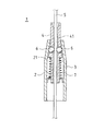
以下、本発明を実施するための最良の形態を、図面に基づいて具体的に説明する。図1は本発明に係る抜き通し型ワイヤチャックの縦断面図であり、図2は該抜き通し形ワイヤチャックの分解斜視図、図3は同じく横断面図である。 The best mode for carrying out the present invention will be specifically described below with reference to the drawings. FIG. 1 is a longitudinal sectional view of a pull-through wire chuck according to the present invention, FIG. 2 is an exploded perspective view of the pull-through wire chuck, and FIG. 3 is a cross-sectional view of the same.
例示形態に係るワイヤチャック10は、異径孔20が貫通形成されたボディ30と、該異径孔20内に収容された中空軸状のスリーブ40と、スリーブ40に支持された2個のギヤ60と、スリーブ40を付勢する付勢手段としてのコイルスプリング70とを備えている。
The
ボディ30は、略筒状で、図中上端が部分的に縮径した外形をなしている。(図1には、ボディ30の内部形状を示すために、ボディ30を半割状態で描いている。)ボディ30の内側に形成された異径孔20は、その上部に上細りのテーパ部21を有しており、テーパ部の下方には、テーパ部の大径側と等しい径の筒部22が連続している。筒部22の略下半部には雌ネジ23が形成されている。異径孔20の内周面には、ギヤ60を案内するためのギヤ案内溝24が、異径孔20の軸心を挟んで相対し、異径孔20の軸方向に延びるように形成されている。また、図3に示すように、ボディ30の下半部には、各種の他部材との接合に便利なように、Dカット加工31が施されている。
The
スリーブ40は、例えば丸棒材を切削加工するなどして形成された部品であり、その軸心にはワイヤ5の太さよりもやや大径のワイヤ挿通孔41が、上端から下端まで貫通形成されている。スリーブ40の中間部には、前記異径孔20のテーパ部21と同程度のテーパ角を有するテーパ軸部42が設けられ、その上側すなわち細径側に、該細径側と等しい径の中径軸部43が連続し、テーパ部21の下側すなわち太径側には、前記中径軸部43よりも細い小径軸部44が連続している。
The
テーパ軸部42を異径孔20のテーパ部21に挿入した状態で、中径軸部43はボディ30の上端開口から十分な長さで突出し、小径軸部44はボディ30の下端開口から十分な長さで突出するように形成されている。中径軸部43の上端におけるワイヤ挿通孔41の開口は、ワイヤ5の挿入を容易にするため、内周面がラッパ状に拡径している。なお、図示は省くが、ボディ30の外に突出させた小径軸部44の下端部近傍には、指先での把持を容易にするため、例えば部分的に拡径したり、あるいは滑り止め加工を施したりした適宜の摘み部が形成されていてもよい。
With the
スリーブ40のテーパ軸部42には、ギヤ装着孔45が、スリーブ40の軸心を挟んで相対するように形成されている。ギヤ装着孔45は、ワイヤ挿通孔41から外周面にかけて、側面視矩形をなす一様の断面形状で、スリーブ40の軸心と直交する方向にテーパ軸部42を貫通している。このギヤ装着孔45には、一対のギヤ60が、軸心を挟んで相対するように装着される。
A
ギヤ60は、セラミックや金属等からなる円筒形状の部材で、その周面には、母線方向に延びる断面山谷状の歯が複数条、形成されている。ギヤ60は、その中心軸を水平にする姿勢でギヤ装着孔45内に収容され、ギヤ装着孔45内で転動しながら、スリーブ40の軸心と直交する方向に移動しうるように保持される。
The
コイルスプリング70は、巻き径が上細りとなるように形成され、スリーブ40の小径軸部44に挿装された状態で異径孔20内に収容される。コイルスプリング70の上端はテーパ軸部42の下側段付面に当接して、スリーブ40を押し上げ方向に付勢する。コイルスプリング70の下端は、異径孔20の筒部22に装着される押え部材80に当接して、異径孔20からの脱落や飛び出しがないように拘束される。
The
押え部材80は、外周面に雄ネジが形成された短筒状の部材で、異径孔20の筒部22に形成された雌ネジ23に螺合される。押え部材80の中心部には、スリーブ40の小径軸部44を遊挿させうる筒孔81が貫通形成されている。押え部材80の下面には、適宜の工具を係合させうるスリ割り82等が形成されている。
The pressing
押え部材80の下方には、吊持される物品9にボディ30を連結するための連結ボルト91等が、必要に応じて取り付けられる。例示形態に係る連結ボルト91は、前記押え部材80の長さを適宜延長したような寸切り状の部材であり、例えば図1に示すように、照明器具等の物品9に形成した適宜の取付孔に挿通されて、ナット92が締結されることにより、物品9と一体に固定される。ただし、物品9との連結形態は、これに限らず、個々の物品形状に応じた公知の連結形態を、適宜採用することができる。
Below the
この抜き通し型ワイヤチャック10の組み立て作業に際しては、スリーブ40のギヤ装着孔45にギヤ60を装着した状態で、そのスリーブ40をボディ30の異径孔20に挿入するのであるが、このとき、スリーブ40の側方に突出したギヤ60の一部を、異径孔20に形成したギヤ案内溝24に沿わせて異径孔20の奥方へと案内することにより、ギヤ60が、ずれたり脱落したりせずに、正しい姿勢で異径孔20のテーパ部21内にセットされる。スリーブ40及びギヤ60が異径孔20内にセットされたならば、続いてスリーブ40の小径軸部44にコイルスプリング70を挿装し、さらに押え部材80を螺合して抜け止めする。
In assembling the pull-out
この抜き通し型ワイヤチャック10を用いた吊り下げ作業に際しては、吊持する物品9と抜き通し型ワイヤチャック10とを、連結ボルト91等を介して予め連結しておく。そして、天井から懸垂させたワイヤ5を、スリーブ40の上方からワイヤ挿通孔41に挿し込む。物品9を片手で支承しつつ、スリーブ40を若干、下方に押し下げるようにしながらワイヤ5を押し込むと、ギヤ60がギヤ装着孔45内で外側に押し退けられ、ワイヤ5の先端が簡単にワイヤ挿通孔41の下方に通り抜ける。そして、下方に通り抜けたワイヤ5の下端を引っ張って緊張させながら、物品9を所定の高さまで持上げて手放すと、ギヤ60がワイヤ5と異径孔20との間に挟圧されてワイヤ5の側面に食い込み、ワイヤ5を固定する。
In the hanging operation using the pull-out
吊り下げ高さを調整する場合は、ワイヤ5の下端を引っ張って緊張させながら、物品9を下方から手で支え、スリーブ40を押し下げて、ギヤ60の挟圧状態を解除する。このとき、物品9の上方からスリーブ40の中径軸部43を押し下げる操作が困難であれば、物品9の下方から、スリーブ40の小径軸部44の突出部分を掴んで引き下げることもできる。物品9が所望の高さに位置決めされたならば、手で支えていた物品9を静かに放すか、スリーブ40を若干、押し上げることにより、ギヤ60がワイヤ5に食い込んで、即座にチャック機能が発揮される。
When adjusting the suspending height, the
本発明の抜き通し型ワイヤチャック10は、このように構成されているので、山谷状の歯を形成したギヤ60の周面が、ワイヤ5の側面に素早く食いつき、ワイヤ5との間に大きい摩擦力を発揮する。したがって、位置決めの際にワイヤ5が滑ってワイヤ5の固定位置がずれることを防止できる。また、揺れや振動によってもワイヤ5が緩みにくくなり、長期間にわたって高い挟持力が発揮される。
Since the punch-out
さらに、ボディ30にはギヤ案内溝24が形成されているので、ギヤ60を装着したスリーブ40をボディ30の異径孔20に挿入する組み立て作業が容易になるとともに、ギヤ60の挟圧姿勢も常時、安定して、ギヤ60のずれや引っ掛かり等による作動不良が生じにくくなる。
Further, since the
10 抜き通し型ワイヤチャック
20 異径孔
21 テーパ部
24 ギヤ案内溝
30 ボディ
40 スリーブ
41 ワイヤ挿通孔
42 テーパ軸部
45 ギヤ装着孔
60 ギヤ(係止部材)
5 ワイヤ
70 コイルスプリング(付勢手段)
DESCRIPTION OF
5
Claims (4)
前記係止部材が、円筒体の周面に断面山谷状の歯を形成したギヤであることを特徴とする抜き通し型ワイヤチャック。 In the axial direction of the different diameter hole in the different diameter hole in a state where the wire is inserted through the body through which the different diameter hole having the tapered portion is formed and the wire insertion hole formed through the axis. A sleeve accommodated so as to be able to advance and retreat; at least one locking member supported by the sleeve so as to be movable in a direction perpendicular to the axis of the sleeve; and the sleeve disposed in the body and having the different diameter. And a biasing means for biasing toward the small diameter side of the hole, and fixing the wire in the sleeve by clamping the locking member between the wire inserted into the sleeve and the hole of different diameter In through wire chuck,
The pull-out type wire chuck, wherein the locking member is a gear having teeth having a cross-sectional shape in the circumferential surface of a cylindrical body.
スリーブは、異径孔のテーパ部に合致するテーパ形状を有して該テーパ部に挿入されるテーパ軸部を備え、該テーパ軸部にはスリーブの軸心と直交する方向にテーパ軸部を貫通する側面視矩形のギヤ装着孔が形成され、このギヤ装着孔にギヤが装着されることを特徴とする抜き通し型ワイヤチャック。 The punch-out type wire chuck according to claim 1,
The sleeve includes a tapered shaft portion that has a tapered shape that matches the tapered portion of the different-diameter hole and is inserted into the tapered portion, and the tapered shaft portion has a tapered shaft portion in a direction orthogonal to the axial center of the sleeve. A through-type wire chuck characterized in that a rectangular gear mounting hole penetrating in a side view is formed, and a gear is mounted in the gear mounting hole.
ボディの異径孔の内周面には異径孔の軸方向に延びるギヤ案内溝が形成され、スリーブのギヤ装着孔にギヤを装着した状態で、該スリーブをボディの異径孔に挿入する際に、スリーブの側方に突出したギヤの一部が前記ギヤ案内溝に沿って異径孔の奥方へと案内されることを特徴とする抜き通し型ワイヤチャック。 The punch-out type wire chuck according to claim 2,
A gear guide groove extending in the axial direction of the different-diameter hole is formed on the inner peripheral surface of the different-diameter hole of the body, and the sleeve is inserted into the different-diameter hole of the body in a state where the gear is attached to the gear attachment hole of the sleeve. In this case, a part of the gear protruding to the side of the sleeve is guided to the back of the different diameter hole along the gear guide groove.
スリーブの一端が、異径孔の大径側に向けてボディ外まで延出されたことを特徴とする抜き通し型ワイヤチャック。 The pull-out type wire chuck according to any one of claims 1 to 3,
A pull-out type wire chuck characterized in that one end of the sleeve is extended to the outside of the body toward the larger diameter side of the different diameter hole.
Priority Applications (1)
| Application Number | Priority Date | Filing Date | Title |
|---|---|---|---|
| JP2008260871A JP2010090973A (en) | 2008-10-07 | 2008-10-07 | Penetration type wire chuck |
Applications Claiming Priority (1)
| Application Number | Priority Date | Filing Date | Title |
|---|---|---|---|
| JP2008260871A JP2010090973A (en) | 2008-10-07 | 2008-10-07 | Penetration type wire chuck |
Publications (1)
| Publication Number | Publication Date |
|---|---|
| JP2010090973A true JP2010090973A (en) | 2010-04-22 |
Family
ID=42253903
Family Applications (1)
| Application Number | Title | Priority Date | Filing Date |
|---|---|---|---|
| JP2008260871A Pending JP2010090973A (en) | 2008-10-07 | 2008-10-07 | Penetration type wire chuck |
Country Status (1)
| Country | Link |
|---|---|
| JP (1) | JP2010090973A (en) |
Cited By (9)
| Publication number | Priority date | Publication date | Assignee | Title |
|---|---|---|---|---|
| KR101796421B1 (en) | 2017-06-21 | 2017-11-16 | 주식회사 아이스트 | Cable anchoring devices for tension and opening-closing of membrane and a retractable roof system applied to cable and membrane using of the same devices |
| CN110901920A (en) * | 2019-12-04 | 2020-03-24 | 中国直升机设计研究所 | Operating steel cable connecting device capable of being quickly separated |
| JP2021515662A (en) * | 2018-03-16 | 2021-06-24 | フィッシャー アンド ペイケル ヘルスケア リミテッド | Headgear with unlocking mechanism |
| US11806452B2 (en) | 2012-08-08 | 2023-11-07 | Fisher & Paykel Healthcare Limited | Headgear for patient interface |
| US11813384B2 (en) | 2014-09-16 | 2023-11-14 | Fisher & Paykel Healthcare Limited | Intramold headgear |
| US11819618B2 (en) | 2016-03-16 | 2023-11-21 | Fisher & Paykel Healthcare Limited | Intra-mould substrate |
| US11819620B2 (en) | 2016-03-16 | 2023-11-21 | Fisher & Paykel Healthcare Limited | Directional lock for interface headgear arrangement |
| US11850365B2 (en) | 2016-03-16 | 2023-12-26 | Fisher & Paykel Healthcare Limited | Strap assembly, strap connector, headgear, headgear assembly, method of forming headgear, tubular connector, patient interface and method of joining straps |
| US11865263B2 (en) | 2009-12-23 | 2024-01-09 | Fisher & Paykel Healthcare Limited | Patient interface and headgear |
-
2008
- 2008-10-07 JP JP2008260871A patent/JP2010090973A/en active Pending
Cited By (11)
| Publication number | Priority date | Publication date | Assignee | Title |
|---|---|---|---|---|
| US11865263B2 (en) | 2009-12-23 | 2024-01-09 | Fisher & Paykel Healthcare Limited | Patient interface and headgear |
| US11806452B2 (en) | 2012-08-08 | 2023-11-07 | Fisher & Paykel Healthcare Limited | Headgear for patient interface |
| US11813384B2 (en) | 2014-09-16 | 2023-11-14 | Fisher & Paykel Healthcare Limited | Intramold headgear |
| US11819618B2 (en) | 2016-03-16 | 2023-11-21 | Fisher & Paykel Healthcare Limited | Intra-mould substrate |
| US11819620B2 (en) | 2016-03-16 | 2023-11-21 | Fisher & Paykel Healthcare Limited | Directional lock for interface headgear arrangement |
| US11850365B2 (en) | 2016-03-16 | 2023-12-26 | Fisher & Paykel Healthcare Limited | Strap assembly, strap connector, headgear, headgear assembly, method of forming headgear, tubular connector, patient interface and method of joining straps |
| KR101796421B1 (en) | 2017-06-21 | 2017-11-16 | 주식회사 아이스트 | Cable anchoring devices for tension and opening-closing of membrane and a retractable roof system applied to cable and membrane using of the same devices |
| JP2021515662A (en) * | 2018-03-16 | 2021-06-24 | フィッシャー アンド ペイケル ヘルスケア リミテッド | Headgear with unlocking mechanism |
| JP7297781B2 (en) | 2018-03-16 | 2023-06-26 | フィッシャー アンド ペイケル ヘルスケア リミテッド | Headgear with unlocking mechanism |
| US11878119B2 (en) | 2018-03-16 | 2024-01-23 | Fisher & Paykel Healthcare Limited | Headgear with lock disengagement mechanism |
| CN110901920A (en) * | 2019-12-04 | 2020-03-24 | 中国直升机设计研究所 | Operating steel cable connecting device capable of being quickly separated |
Similar Documents
| Publication | Publication Date | Title |
|---|---|---|
| JP2010090973A (en) | Penetration type wire chuck | |
| JP5826574B2 (en) | Wall fittings | |
| US20150033915A1 (en) | Drive bit | |
| US20090013575A1 (en) | Hanger | |
| US7513477B2 (en) | Adjustable hanging device | |
| JP2009136976A (en) | Tool holder | |
| US9694480B2 (en) | Nut driving cleaning system | |
| JP2020058327A (en) | Fishing bait attaching device | |
| JP2007218044A (en) | Wire guide structure for wire type window regulator | |
| AU9710701A (en) | Nut assembly | |
| GB2473473A (en) | Device to aid the passage of an elongate member through a drilled hole | |
| US914174A (en) | Screw-holder for screw-drivers. | |
| JP2007276098A (en) | Screw holding tube for screwdriver | |
| JP5093556B2 (en) | Ring body holder | |
| JP2009041731A (en) | Rivet holding body | |
| JP5265802B1 (en) | Fixture | |
| JP2005265117A (en) | Penetration type wire chuck | |
| JP2013165764A (en) | Guide wire grip | |
| JP2510825Y2 (en) | Wire upholstery | |
| JP2005240931A (en) | Wire gripper | |
| JP2523750Y2 (en) | Wire upholstery | |
| JP4913167B2 (en) | Plasterboard thumbtack | |
| KR200235437Y1 (en) | A Peace Lead Hold for Fishing Tackle | |
| US721884A (en) | Screw-driver attachment. | |
| JPH0611565U (en) | Hanging tool |