EP4172046B1 - Verfahren zur herstellung einer verpackung aus einem wiederverwertbaren material - Google Patents
Verfahren zur herstellung einer verpackung aus einem wiederverwertbaren material Download PDFInfo
- Publication number
- EP4172046B1 EP4172046B1 EP21783507.3A EP21783507A EP4172046B1 EP 4172046 B1 EP4172046 B1 EP 4172046B1 EP 21783507 A EP21783507 A EP 21783507A EP 4172046 B1 EP4172046 B1 EP 4172046B1
- Authority
- EP
- European Patent Office
- Prior art keywords
- glue
- tube
- sealing joint
- section
- flat sheet
- Prior art date
- Legal status (The legal status is an assumption and is not a legal conclusion. Google has not performed a legal analysis and makes no representation as to the accuracy of the status listed.)
- Active
Links
Images



Classifications
-
- B—PERFORMING OPERATIONS; TRANSPORTING
- B65—CONVEYING; PACKING; STORING; HANDLING THIN OR FILAMENTARY MATERIAL
- B65B—MACHINES, APPARATUS OR DEVICES FOR, OR METHODS OF, PACKAGING ARTICLES OR MATERIALS; UNPACKING
- B65B9/00—Enclosing successive articles, or quantities of material, e.g. liquids or semiliquids, in flat, folded, or tubular webs of flexible sheet material; Subdividing filled flexible tubes to form packages
- B65B9/06—Enclosing successive articles, or quantities of material, in a longitudinally-folded web, or in a web folded into a tube about the articles or quantities of material placed upon it
- B65B9/08—Enclosing successive articles, or quantities of material, in a longitudinally-folded web, or in a web folded into a tube about the articles or quantities of material placed upon it in a web folded and sealed transversely to form pockets which are subsequently filled and then closed by sealing
-
- B—PERFORMING OPERATIONS; TRANSPORTING
- B65—CONVEYING; PACKING; STORING; HANDLING THIN OR FILAMENTARY MATERIAL
- B65B—MACHINES, APPARATUS OR DEVICES FOR, OR METHODS OF, PACKAGING ARTICLES OR MATERIALS; UNPACKING
- B65B51/00—Devices for, or methods of, sealing or securing package folds or closures; Devices for gathering or twisting wrappers, or necks of bags
- B65B51/02—Applying adhesives or sealing liquids
-
- B—PERFORMING OPERATIONS; TRANSPORTING
- B65—CONVEYING; PACKING; STORING; HANDLING THIN OR FILAMENTARY MATERIAL
- B65B—MACHINES, APPARATUS OR DEVICES FOR, OR METHODS OF, PACKAGING ARTICLES OR MATERIALS; UNPACKING
- B65B51/00—Devices for, or methods of, sealing or securing package folds or closures; Devices for gathering or twisting wrappers, or necks of bags
- B65B51/10—Applying or generating heat or pressure or combinations thereof
-
- B—PERFORMING OPERATIONS; TRANSPORTING
- B65—CONVEYING; PACKING; STORING; HANDLING THIN OR FILAMENTARY MATERIAL
- B65B—MACHINES, APPARATUS OR DEVICES FOR, OR METHODS OF, PACKAGING ARTICLES OR MATERIALS; UNPACKING
- B65B51/00—Devices for, or methods of, sealing or securing package folds or closures; Devices for gathering or twisting wrappers, or necks of bags
- B65B51/10—Applying or generating heat or pressure or combinations thereof
- B65B51/14—Applying or generating heat or pressure or combinations thereof by reciprocating or oscillating members
-
- B—PERFORMING OPERATIONS; TRANSPORTING
- B65—CONVEYING; PACKING; STORING; HANDLING THIN OR FILAMENTARY MATERIAL
- B65B—MACHINES, APPARATUS OR DEVICES FOR, OR METHODS OF, PACKAGING ARTICLES OR MATERIALS; UNPACKING
- B65B51/00—Devices for, or methods of, sealing or securing package folds or closures; Devices for gathering or twisting wrappers, or necks of bags
- B65B51/10—Applying or generating heat or pressure or combinations thereof
- B65B51/26—Devices specially adapted for producing transverse or longitudinal seams in webs or tubes
-
- B—PERFORMING OPERATIONS; TRANSPORTING
- B65—CONVEYING; PACKING; STORING; HANDLING THIN OR FILAMENTARY MATERIAL
- B65B—MACHINES, APPARATUS OR DEVICES FOR, OR METHODS OF, PACKAGING ARTICLES OR MATERIALS; UNPACKING
- B65B51/00—Devices for, or methods of, sealing or securing package folds or closures; Devices for gathering or twisting wrappers, or necks of bags
- B65B51/10—Applying or generating heat or pressure or combinations thereof
- B65B51/26—Devices specially adapted for producing transverse or longitudinal seams in webs or tubes
- B65B51/30—Devices, e.g. jaws, for applying pressure and heat, e.g. for subdividing filled tubes
-
- B—PERFORMING OPERATIONS; TRANSPORTING
- B65—CONVEYING; PACKING; STORING; HANDLING THIN OR FILAMENTARY MATERIAL
- B65B—MACHINES, APPARATUS OR DEVICES FOR, OR METHODS OF, PACKAGING ARTICLES OR MATERIALS; UNPACKING
- B65B9/00—Enclosing successive articles, or quantities of material, e.g. liquids or semiliquids, in flat, folded, or tubular webs of flexible sheet material; Subdividing filled flexible tubes to form packages
- B65B9/06—Enclosing successive articles, or quantities of material, in a longitudinally-folded web, or in a web folded into a tube about the articles or quantities of material placed upon it
-
- B—PERFORMING OPERATIONS; TRANSPORTING
- B65—CONVEYING; PACKING; STORING; HANDLING THIN OR FILAMENTARY MATERIAL
- B65B—MACHINES, APPARATUS OR DEVICES FOR, OR METHODS OF, PACKAGING ARTICLES OR MATERIALS; UNPACKING
- B65B9/00—Enclosing successive articles, or quantities of material, e.g. liquids or semiliquids, in flat, folded, or tubular webs of flexible sheet material; Subdividing filled flexible tubes to form packages
- B65B9/10—Enclosing successive articles, or quantities of material, in preformed tubular webs, or in webs formed into tubes around filling nozzles, e.g. extruded tubular webs
- B65B9/20—Enclosing successive articles, or quantities of material, in preformed tubular webs, or in webs formed into tubes around filling nozzles, e.g. extruded tubular webs the webs being formed into tubes in situ around the filling nozzles
-
- B—PERFORMING OPERATIONS; TRANSPORTING
- B65—CONVEYING; PACKING; STORING; HANDLING THIN OR FILAMENTARY MATERIAL
- B65D—CONTAINERS FOR STORAGE OR TRANSPORT OF ARTICLES OR MATERIALS, e.g. BAGS, BARRELS, BOTTLES, BOXES, CANS, CARTONS, CRATES, DRUMS, JARS, TANKS, HOPPERS, FORWARDING CONTAINERS; ACCESSORIES, CLOSURES, OR FITTINGS THEREFOR; PACKAGING ELEMENTS; PACKAGES
- B65D65/00—Wrappers or flexible covers; Packaging materials of special type or form
- B65D65/38—Packaging materials of special type or form
- B65D65/46—Applications of disintegrable, dissolvable or edible materials
- B65D65/466—Bio- or photodegradable packaging materials
-
- B—PERFORMING OPERATIONS; TRANSPORTING
- B65—CONVEYING; PACKING; STORING; HANDLING THIN OR FILAMENTARY MATERIAL
- B65D—CONTAINERS FOR STORAGE OR TRANSPORT OF ARTICLES OR MATERIALS, e.g. BAGS, BARRELS, BOTTLES, BOXES, CANS, CARTONS, CRATES, DRUMS, JARS, TANKS, HOPPERS, FORWARDING CONTAINERS; ACCESSORIES, CLOSURES, OR FITTINGS THEREFOR; PACKAGING ELEMENTS; PACKAGES
- B65D75/00—Packages comprising articles or materials partially or wholly enclosed in strips, sheets, blanks, tubes or webs of flexible sheet material, e.g. in folded wrappers
- B65D75/40—Packages formed by enclosing successive articles, or increments of material, in webs, e.g. folded or tubular webs, or by subdividing tubes filled with liquid, semi-liquid, or plastic materials
- B65D75/44—Individual packages cut from webs or tubes
-
- B—PERFORMING OPERATIONS; TRANSPORTING
- B65—CONVEYING; PACKING; STORING; HANDLING THIN OR FILAMENTARY MATERIAL
- B65B—MACHINES, APPARATUS OR DEVICES FOR, OR METHODS OF, PACKAGING ARTICLES OR MATERIALS; UNPACKING
- B65B41/00—Supplying or feeding container-forming sheets or wrapping material
- B65B41/12—Feeding webs from rolls
- B65B41/16—Feeding webs from rolls by rollers
-
- B—PERFORMING OPERATIONS; TRANSPORTING
- B65—CONVEYING; PACKING; STORING; HANDLING THIN OR FILAMENTARY MATERIAL
- B65B—MACHINES, APPARATUS OR DEVICES FOR, OR METHODS OF, PACKAGING ARTICLES OR MATERIALS; UNPACKING
- B65B61/00—Auxiliary devices, not otherwise provided for, for operating on sheets, blanks, webs, binding material, containers or packages
- B65B61/04—Auxiliary devices, not otherwise provided for, for operating on sheets, blanks, webs, binding material, containers or packages for severing webs, or for separating joined packages
- B65B61/06—Auxiliary devices, not otherwise provided for, for operating on sheets, blanks, webs, binding material, containers or packages for severing webs, or for separating joined packages by cutting
Definitions
- the present invention relates to a method for producing a packaging by providing a flat sheet, folding the flat sheet into a tube, filling the tube with a substance and heat sealing sections of the tube to enclose the substance inside the packaging.
- An example for a method for producing a packaging is disclosed in US 2019/344915 A1 .
- the invention further relates to a packaging enclosing a substance and a machine for producing this packaging.
- a majority of single- and multi-serve packaging e.g. used for coffee beans, are made from plastic materials due to their beneficial characteristics.
- these materials offer advantages, such as durability, flexibility, low weight, provision of long shelf-life and letting the taste of the enclosed product unaltered.
- a packaging can be manufactured from such materials efficiently and reliably. Unfortunately, reusing and recycling such packaging materials is challenging.
- paper-based materials are proposed as alternative packaging materials as they can be recycled more easily compared to plastic materials.
- alternative materials do not have the same or very different material properties as established materials, like plastic or aluminium.
- packages made from alternative materials often have a limited shelf-life as they do not provide the same oxygen and moisture barrier as aluminium or plastic.
- different production methods are required as alternative materials also differ from known materials in material characteristics that are relevant for forming and sealing a packaging.
- a stick pack or a sachet packaging from established materials such that the content inside the respective package is hermetically sealed. Thereby, the risk of biological degradation from bacterial contamination, oxidation or moisture can be reduced. In comparison, the provision of a stick pack or sachet packaging made from a paper material does not allow to seal the packaging reliably and consistently.
- the bending stiffness and deformation resistance of the paper material impedes a reliable sealing of the packaging in places, where, for example, more than two layers of paper material are joined or where sealing lines intersect.
- the paper material must have a relatively high thickness in comparison to the dimensions relating to bending radius and joining sections of the packaging to provide sufficient tearing strength. Therefore, the different layers are prone to spring back into their original position or peel off directly after a joining attempt. This leads to gaps, holes or voids within the designated sealing lines so that it is not possible to provide a hermetically sealed packaging with paper based materials. This is particularly disadvantageous for packaging intended to be used for foodstuff or pharmaceutical products.
- a first aspect of the invention relates to a method for producing a packaging for enclosing a substance.
- the method comprises the step of providing a flat sheet made of a recyclable paper material, which has two opposite side edge sections.
- flat sheet may be understood as a portion of paper that may be thin in comparison to its length and may have at least one even surface, for instance.
- the expression "recyclable” may be understood, for example, as a material that can be reused entirely for a new product or purpose after having been treated mechanically or chemically using an industrial or natural process.
- the paper material used in the invention may be collected after usage and may be mixed with water and chemicals to break it down. It is heated up and broken up into strands of cellulose. Plastic coatings and ink may be removed as long as they do not exceed a certain amount, for example by filtering.
- the amount of a plastic coating on the recycled material or the amount of polymer content in the recyclable material may only be up to about 20%, preferably up to about 15%, more preferably up to about 10%, and most preferably up to about 5%, of its total weight.
- the flat sheet is formed into a tube by folding the flat sheet so that the two side edge sections at least partially overlap each other at an overlapping section.
- the tube is heat sealed along the overlapping section to form a longitudinal sealing joint. Further, the tube is heat sealed across the longitudinal sealing joint to close the tube with a first traverse sealing joint at a first tube end.
- the tube is filled with a substance to be packed.
- substance may be understood, for example, as any type of solid, liquid, at least partially soluble and/or percolate-able matter, which may have a particular or definite chemical constitution.
- substances may be cosmetic, medical or food products, such as cereals, roasted ground coffee, instant coffee, coffee mixes, creamer, tealeaves, chocolate or dairy products, or dehydrated edible substances.
- the tube is heat sealed across the longitudinal sealing joint to close the tube with a second traverse sealing joint at a second tube end opposite to the first tube end with respect to the substance to be packed such that the packaging enclosing said substance is formed.
- a first amount of glue is applied onto the flat sheet at a first triple point section.
- the longitudinal sealing joint and the first traverse sealing joint intersect.
- a second amount of glue is applied onto the flat sheet at a second triple point section.
- the longitudinal sealing joint and the second traverse sealing joint intersect. The glue seals the respective triple point section upon heat sealing of the respective tube end to form the respective traverse sealing joint.
- glue may be understood, for example, as any substance that may be applied to surfaces of portions between which a (structural / permanent / temporary) bond is to be established.
- the present invention provides a method that facilitates the production of a packaging that not only (hermetically) sealingly encases, wraps or covers the substance to be packed but that can be recycled easily and efficiently after being used.
- a side edge section may be understood as any part or portion of the flat sheet that extends from one of the two opposite side edges towards the other side edge, for example.
- the method provides further to fold the flat sheet into a tube by folding the flat sheet such that the two side edge sections at least partially overlap.
- the two side edge sections may be arranged in the folded state such that they may extend over each other such that they may both cover a portion of the tube, which may be the overlapping section.
- one of the side edge sections may project/overhang the other one in the folded state.
- the two side edges may be arranged flush with each other.
- the side edge sections may face each other with the same side of the flat sheet.
- the overlapping section can be formed such that it protrudes from the packaging.
- the overlapping section can be formed such that both side edge sections or the overlapping section are positioned at an outer side of the packaging.
- the tube is then to be sealed lengthwise by heat sealing.
- the sealing direction may comprise at least one component corresponding with the longitudinal axis of the tube.
- heat and pressure may be applied to influence the material of the surfaces to be sealed.
- the two ends of the tube are heat sealed across the longitudinal sealing joint with traverse sealing joints, respectively.
- the traverse sealing joints may run in an oblique or winded manner relative to the longitudinal sealing joint so that it is not necessary (while not being excluded at the same time) that the traverse sealing joints are orthogonal to the longitudinal sealing joint. Thereby, it is possible to enclose/encase/wrap the substance, which is filled into the packaging, from all sides.
- the respective amount of glue may be applied before the step of forming the flat sheet into the tube.
- the first amount of glue and/or the second amount of glue may be applied as a spot of glue.
- the glue may be a structural adhesive that may harden via processes such as evaporation of a solvent, reaction with UV radiation, chemical reactions, or adapting its temperature.
- the glue may be a pressure-sensitive adhesive to form a bond by applying a certain amount of pressure to bind the adhesive to the surface to be joined.
- the glue may (be configured to) change from a liquid state, in which the glue may be flowable, to a solid state, in which the glue may be dry.
- the physical state of the glue may depend on the temperature and/or pressure.
- the glue may melt at a temperature between 50 degree Celsius and 220 degree Celsius, preferably between 90 degree Celsius and 180 degree Celsius.
- the glue may be a hotmelt glue, for instance.
- the glue may be dry before the step of forming the flat sheet into the tube or at least before the step of heat sealing the tube to form the longitudinal sealing joint.
- the dried glue may be reactivated upon the respective heat sealing step by melting the glue such that the glue is flowable and seals the respective triple point section after drying.
- the glue may seal the respective triple point section such that the longitudinal sealing joint as well as the first and second traverse sealing joints form a hermetic sealing of the packaging.
- hermetic sealing may be understood, for example, as a gas-proof sealing.
- dry may be understood, for example, as the glue having changed from a liquid and/or flowable state to a hardened state.
- at least the outside contour of the glue may be solid.
- the glue in the hardened state the glue may have solidified entirely.
- the glue may be only or more capable of bonding in a liquid state.
- flowable may be understood, for example, as the characteristic of a viscous liquid or paste to move or spread freely without being intensely limited or restricted by intermolecular forces.
- the expression "reactivated” may be understood, for example, as changing the capabilities of the glue from a state, in which no new bonding(s) can be formed, to a state, in which the glue is capable of forming new (intermolecular/surface) bonds.
- the production process of the packaging can be improved because the glue can be applied in a liquid state from a gluing pistol and then can be dried so that subsequent process steps are not affected by the glue being wet, which may be disadvantageous, for example, when folding the flat sheet.
- the glue can be applied in a liquid state from a gluing pistol and then can be dried so that subsequent process steps are not affected by the glue being wet, which may be disadvantageous, for example, when folding the flat sheet.
- the glue may be a recyclable, incinerable, biodegradable and/or compostable material.
- biodegradable material may be understood as any material that can be broken down into environmentally innocuous products by (the action of) living things (such as microorganisms, e.g. bacteria, fungi or algae).
- suitable glue substances may be polyvinyl alcohol (PVOH), ethylene vinyl alcohol (EVOH), polyvinyl acetate (PVAc), wax, polyolefins (PO) and/or acrylic components.
- the glue may be a PO-based or an acrylic-based hotmelt adhesive or glue.
- the flat sheet material may comprise a laminated and/or multi-layered structure with a base layer made of a paper material and a sealant layer. Therein, the glue may be (directly) applied onto the sealant layer.
- the flat sheet may have various (layer) configurations, forms and shapes.
- laminated / layered structure may be understood, for example, as a structure comprising different parts that are arranged in plies, slats, tiers or as strata.
- the flat sheet with an arbitrary number of layers that each can provide a desired functionality, such as, for example, a layer for sealing, (a further layer) for forming a (moisture/oxygen) barrier, and/or for providing a sealant or adhesive (such as, for example, said sealant layer).
- the production process of the packaging can be improved as the packaging can be produced with refitted already existing and accessible production equipment.
- the step of providing the flat sheet may comprise the step of unrolling a longitudinal flat sheet material from a paper reel.
- the step of providing the flat sheet may further comprise the step of longitudinally cutting the flat sheet material into separate flat sheets, of which each has the two opposite side edge sections.
- a plurality of packages may be formed in series. Therein, neighbouring packages may share a transverse sealing joint that forms the first traverse sealing joint of one of the packages and the second traverse sealing joint of the neighbouring package.
- the first amount of glue of one of two neighbouring packages may be provided together with the second amount of glue of its neighbouring package.
- the step of heat sealing the tube to form the second traverse sealing joint may be followed by a step of separating the packages.
- the separating may be completed by a transverse cutting step.
- the step of heat sealing the tube to form the second traverse sealing joint may be followed by a step of weakening a connection section, which preferably may be the shared transverse sealing j oint, to form a tear line.
- a further aspect of the present invention relates to a packaging being made of a flat sheet with two opposite side edge sections and made of a recyclable paper material.
- the packaging encloses a substance.
- the expression “enclose” may be understood, for example, as surrounding, covering, wrapping and/or encasing something, such as the substance, preferably in a sealing manner.
- the packaging comprises a longitudinal sealing joint along an overlapping section, at which the two opposite side edge sections overlap each other when the flat sheet is folded to form the flat sheet into a tube.
- the packaging further comprises a first traverse sealing joint, which extends across the longitudinal sealing joint to close the tube at a first tube end.
- the packaging also comprises a second traverse sealing joint, which extends across the longitudinal sealing joint to close the tube at a second tube end opposite to the first tube end with respect to the enclosed substance.
- the packaging comprises a first amount of glue that seals a first triple point section, at which the longitudinal sealing joint and the first traverse sealing joint intersect, and a second amount of glue that seals a second triple point section, at which the longitudinal sealing joint and the second traverse sealing joint intersect.
- the flat sheet may comprise a multi-layered structure comprising a base layer made of a paper material and a sealant layer.
- the sealant layer may be provided on at least one of the two opposite side surfaces of the flat sheet.
- the sealant layer may be provided as a coating or a laminate that acts as a sealant during heat sealing.
- the thickness of the base layer may be up to 120 microns.
- the base layer may have a thickness between at least 50 microns and (at most) 120 microns.
- the sealant layer may have a thickness of 5-10 microns, preferably 6-8 microns.
- the packaging may be a single serve pack like a stick pack, or a multi-serve pack like a stand-up pouch, a pillow pack, and/or a gusseted bag.
- the side edge sections may face each other with the same side of the flat sheet.
- the overlapping section may be formed such that it protrudes from the packaging or such that both side edge sections or the overlapping section are positioned at an outer side of the packaging.
- the packaging may be configured to seal hermetically an enclosed food product as the substance.
- the packaging may comprise all aforementioned features or characteristics that are described above for the method according to the first aspect of the invention. For reasons of brevity, explicit reiteration of these features is omitted at this juncture.
- a further aspect of the present invention relates to a machine for producing a packaging for enclosing a substance as described in detail above.
- the machine comprises a feeding system for supplying a flat sheet made of a recyclable paper material and having two opposite side edge sections.
- the machine further comprises a folding section for folding the supplied flat sheet so that the two opposite side edge sections overlap each other at an overlapping section to form the flat sheet into a tube.
- the machine comprises a first heat sealing section for heat sealing the tube along the overlapping section to form a longitudinal sealing joint.
- the machine comprises a second heat sealing section for heat sealing the tube across the longitudinal sealing joint to close the tube with a first traverse sealing joint at a first tube end.
- the machine comprises a filling section for filling the tube with a substance to be packed.
- the machine comprises a third heat sealing section for heat sealing the tube across the longitudinal sealing joint to close the tube with a second traverse sealing joint at a second tube end opposite to the first tube end with respect to the substance to be packed so as to form the packaging enclosing said substance.
- the machine is characterized by further comprising a glue application section.
- the glue application section is suitable (and/or configured) for applying a first amount of glue onto the flat sheet at a first triple point section, at which the longitudinal sealing joint and the first traverse sealing joint will intersect, so that the glue seals the first triple point section upon the heat sealing of the tube at the second heat sealing section to form the first traverse sealing joint.
- the glue application section is further suitable (and/or configured) for applying a second amount of glue onto the flat sheet at a second triple point section, at which the longitudinal sealing joint and the second traverse sealing joint will intersect, so that the glue seals the second triple point section upon the heat sealing of the tube at the third heat sealing section to form the second traverse sealing joint.
- the second and third heat sealing sections may be identical or integral.
- the machine is capable of providing glue to such a reduced amount to the starting material that it is possible to maintain the sealant/adhesive content to a level that facilitates recycling of the produced packaging.
- the application of glue in the machine is to be conducted in the described manner, which allows that glue is only applied in places that require additional sealant/adhesive during heat sealing.
- the glue application section may be arranged in the machine such that the glue is dry before arriving at any one of the folding section and the first to third heat sealing sections.
- the machine may be configured (adapted) to complete any or all of the above described steps of the method of the first aspect of the invention.
- the feeding system may comprise a reel feeding system for unrolling a longitudinal flat sheet material from a paper reel to supply the flat sheet.
- the machine may preferably further comprise a cutting section for separating a plurality of packages formed in series.
- the third heat sealing section may be configured to transport the flat sheet from the feeding system to the cutting section preferably by gripping and pulling the second tube end.
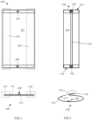
- Figures 1 to 4 illustrate some of the steps of a method for producing a packaging 200 according to the present invention.
- Figure 5 shows aspects of the packaging 200 according to the present invention.
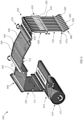
- Figures 6 and 7 exemplarily illustrate aspects of a machine 600 for producing the packaging 200 in accordance with the present invention.
- the method for producing the packaging 200 for enclosing a substance 500 comprises a step of providing a flat sheet 100 made of a recyclable paper material and having two opposite side edge sections 101, 102.
- the side edge sections 101, 102 may extend from a respective side edge of the flat sheet 100 towards the opposite side edge section 101, 102, respectively.
- the two side edge section 101, 102 may form together the complete side surface of the flat sheet 100.
- the flat sheet 100 may also have two opposite side surfaces 111, 112.
- the flat sheet 100 may have any shape or form.
- the flat sheet may have a (substantially) quadratic or rectangular form, such as exemplarily illustrated in Figure 1 . However, this is not a complete enumeration.
- the flat sheet material may comprise paper (e.g. (exclusively or at least primarily) made of cellulose fibres, such as cellulose fibres derived from wood, grass, and/or bamboo) as well as further (arbitrary) components that may or may not be recyclable or biodegradable.
- the further components which may, for example, be a plastic coating or other polymer content, would be limited to a quantity of up to about 20%, preferably up to about 15%, more preferably up to about 10%, and most preferably up to about 5%, of the total weight of the (entire) flat sheet material (so to render the flat sheet material still recyclable).
- the further components may be provided as layers, laminates on the paper material, it is also conceivable that the further components may be mixed or blended into the paper material itself. However, these are only examples and do not represent a complete enumeration.
- the flat sheet material may comprise a laminated and/or multi-layered structure.
- the flat sheet 100 (or the flat sheet material) may comprise a base layer and a sealant layer (not shown). It is also conceivable that the flat sheet material may comprise additional layers, which preferably may or may not be of a recyclable, biodegradable and/or compostable material.
- the base layer may be made of a paper material.
- the base layer may have a grammage between 40 g/m 2 and 120 g/m 2 , preferably between 50 g/m 2 and 80 g/m 2 .
- gsm meaning "grams per square meter”.
- suitable recyclable paper material may be machine glazed paper or metallized paper.
- the machine glazed paper may be a paper without any coating and one side thereof may have a smooth surface while the side opposite thereto may have a rough surface.
- Metallized paper may be a paper coated with a layer of metal, such as aluminium, whereby preferably the coating may be applied by lamination or vacuum metallization.
- the sealant layer may have a thickness of 5 to 10 microns, preferably 6 to 8 microns.
- materials to be used as a sealant layer may be a polyolefin dispersion or an acrylic coating.
- the sealant layer may have a grammage between 1 g/m 2 and 15 g/m 2 , preferably between 4 g/m 2 and 10 g/m 2 .
- the sealant layer may be configured to melt by applying temperatures onto the flat sheet 100 in the range of 150 degree Celsius to 220 degree Celsius. Alternatively or additionally, the sealant layer may change its physical state or binding characteristics under pressure or exposure with (UV) radiation.
- the sealant layer may be provided on at least one of the two opposite side surfaces 111, 112 of the flat sheet 100.
- the sealant layer may be a coating that acts as a sealant in a heat-sealing process.
- the flat sheet 100 may be provided by unrolling a longitudinal flat sheet material.
- the flat sheet 100 may be unrolled from a paper reel 611 arranged in the machine 600.
- the flat sheet 100 may be provided such that a wide longitudinal flat sheet material may be unrolled, longitudinally cut (e.g. by circular knifes) into separate flat sheets 100 such that the so separated flat sheet 100 has the two opposite side edge sections 101, 102, respectively. This is exemplarily shown in Figures 6 and 7 .
- the flat sheet 100 is formed into a tube 120 by folding the flat sheet 100 so that the two side edge sections 101, 102 at least partially overlap each other at an overlapping section 123.
- the side edge sections 101, 102 may face each other with the same side of the flat sheet 100.
- the two side edge sections 101, 102 may be folded such that they come to rest on each other with the same side of the flat sheet 100.
- This is exemplarily shown in Figures 2 to 4 , where the two side edge sections 101, 102 face each other with a first side surface 111.
- the tube 120 is heat sealed along the overlapping section 123 to form a longitudinal sealing joint 130.
- Figures 2 and 3 show this exemplarily.
- the tube 120 may have a first tube end 121 and a second tube end 122, between which preferably the longitudinal sealing joint 130 may at least partially, preferably fully, extend.
- Figures 2 and 5 show this exemplarily.
- the (sealed) overlapping section 123 may be formed such that it protrudes from the packaging 200, preferably in the sealed state.
- the (sealed) overlapping section 123 may also be formed such that it protrudes from the packaging 200 or such that both side edge sections 101, 102 or the overlapping section 123 are positioned at an outer side of the packaging 200.
- Figures 2 and 5 show this exemplarily.
- the tube 120 is heat sealed across the longitudinal sealing joint 130 to close the tube 120 with a first traverse sealing joint 141 at the first tube end 121 (e.g. shown in Figure 5 ).
- a second heat sealing section 642 may be provided that may comprise two heat sealing jaws 645, 646 that are arranged opposite to each other.
- Figure 4 shows an exemplary embodiment for the second heat sealing section 642.
- the two heat sealing jaws 645, 646 may be (linearly and/or rotationally) movable to each other.
- the heat sealing jaws 645, 646 may be moved between a treatment state, where the tube 120 may be pressed between the two heat sealing jaws 645, 646 to apply a binding force (e.g. between 500 N to 1500 N), a pressure (e.g. between 2 bar and 10 bar) and/or heat (temperature between 150 degree Celsius to 220 degree Celsius) to the tube 120 for a certain amount of time (e.g.
- a binding force e.g. between 500 N to 1500 N
- a pressure e.g. between 2 bar and 10 bar
- heat temperature between 150 degree Celsius to 220 degree Celsius
- the heat sealing jaws 645, 646 may be moved to a release state, where the tube 120 may be movable between (released from) the two heat sealing jaws 645, 646.
- the provision of the first traverse sealing joint 141 is exemplarily depicted, whereby the heat sealing jaws 645, 646 are exemplarily shown in the treatment state.
- both of the heat sealing jaws 645, 646 may be movable or only one of the two heat sealing jaws 645, 646 may be movable.
- the tube 120 is heat sealed across the longitudinal sealing joint 130 to close the tube 120 with a second traverse sealing joint 142 at the second tube end 122, which is opposite to the first tube end 121 with respect to the substance 500 to be packed.
- a second traverse sealing joint 142 may be conducted similarly (or in (exactly) the same way) as exemplarily illustrated in Figure 4 .
- a third heat sealing section 643 may be provided that may have a similar or identical configuration as the aforementioned second heat sealing section 642 (e.g. as illustrated in Figure 4 ).
- the same device is used for heat sealing the first traverse sealing joint 141 and the second traverse sealing joint 142.
- the second and third heat sealing section 642, 643 may be identical/the same device.
- the second heat sealing section 642 may be integral with the third heat sealing section 643. This is exemplarily illustrated in Figure 4 , where the third heat sealing section 643 is indicated by an arrow with a broken line as the third heat sealing section 643 may be hidden behind the second heat sealing section 642 (when seen in side view).
- one of the heat sealing jaws 645, 646 may form the second heat sealing section 642 while the respective other of the two heat sealing jaws 645, 646 may form the third heat sealing section 643.
- the packaging 200 is formed such that it encloses the packed substance 500.
- the longitudinal sealing joint 130 may be sealed onto the tube 120, preferably the first or second traverse sealing joint 141, 142, in a heat-sealing step such that it is fixed thereto.
- Figure 3 may be suitable for indicating such a possible configuration exemplarily.
- the tube 120 is filled with the substance 500 to be packed.
- the substance 500 may be a food product or a medicine product.
- the method further comprises a step of applying a first amount of glue 301 onto the flat sheet 100 at a first triple point section 151.
- a first triple point section 151 At the first triple point section 151, the longitudinal sealing joint 130 and the first traverse sealing joint 141 intersect. This is exemplarily illustrated in Figures 2 , 3 and 5 .
- the method also comprises a step of applying a second amount of glue 302 onto the flat sheet 100 at a second triple point section 152.
- a second triple point section 152 At the second triple point section 152, the longitudinal sealing joint 130 and the second traverse sealing joint 142 intersect. This is exemplarily illustrated in Figures 2 , 3 and 5 .
- the first amount of glue 301 and/or the second amount of glue 302 may be applied as a spot of glue 300. This is exemplarily illustrated in Figures 1 to 6 .
- any of the glue 300-302 may be applied onto the sealant layer.
- the sealant layer may be provided on the first side surface 111 of the flat sheet 100, which may form an inner surface of the tube 120 after the folding step.
- the denomination "glue" may comprise each of the glue 300 to 302.
- the glue 300-302 seals the respective triple point section 151, 152 upon the heat sealing of the respective tube end 121, 122 to form the respective traverse sealing joint 141, 142. This is exemplarily illustrated in Figures 4 and 5 .
- the respective amount of glue 300-302 may be applied before the step of forming the flat sheet 100 into the tube 120. This is illustrated in Figures 1 to 3 , 6 and 7 .
- the glue 300-302 may be dry before the step of forming the flat sheet 100 into the tube 120 or before the step of heat sealing the tube 120 to form the longitudinal sealing joint 130.
- the glue 300-302 may change from a solid state, in which the glue 300-302 is dry, to a liquid state, in which the glue 300-302 is flowable.
- the change of the physical state of the glue 300-302 may be activated by changing the temperature and/or pressure around the glue 300-302.
- the (dried) glue 300-302 may (be configured to) be reactivated upon the respective heat-sealing step by melting the glue 300-302 such that the glue 300-302 is flowable and seals the respective triple point section 151, 152 after drying. This is exemplarily illustrated in Figures 3 and 4 .
- Figure 3 shows exemplarily the tube 120 being mechanically pressed (e.g. by/between the two heat sealing jaws 645, 646) at the first tube end 121 before heat sealing of the first traverse sealing joint 141.
- the glue 301 may have been applied onto the first surface 111 inside the tube 120, the glue 301 may be positioned (as a spot) (directly) below the longitudinal sealing joint 130 and may be in a dry state.
- Figure 3 illustrates that a space S may be formed between the overlapping section 123 and the pressed together mantle portions of the tube 120.
- the glue 301 may be melted and may flow into the space S.
- the space S may be filled and sealed by the glue 301.
- the glue 300 may (be configured to) seal the respective triple point section 151, 152 such that the longitudinal sealing joint 130 as well as the first and second traverse sealing joints 141, 142 may form (together) a hermetic sealing of the packaging 200.
- the size, thickness, shape, and/or position of the first and second amount of glue 301, 302 may influence, for example, the reliability of the sealing of the packaging 200.
- Figure 7 shows examples for suitable positions for the glue application, which are indicated by filled circles and may correspond with the triple point sections 151, 152.
- the shape and/or configuration of the sealing jaws 645, 646 may influence, for example, the melting directions and/or melting behaviour of the glue 300-302.
- suitable materials for the glue 300-302 may be wax or any polyolefin (PO)-based or acrylic-based hotmelt glue or adhesive.
- a plurality of packages 200 may be formed in series. This is exemplarily illustrated in Figures 6 and 7 . Thereby, neighbouring packages 200 may share a shared transverse sealing joint that may form the first traverse sealing joint 141 of one of the packages 200 and the second traverse sealing joint 142 of the neighbouring package 200. Also, the first amount of glue 301 of one of two neighbouring packages 200 may be provided together with the second amount of glue 302 of its neighbouring package 200.
- the method may conclude the process of manufacturing the packaging 200 by separating the packages 200 by a transverse cutting step. This is exemplarily shown in Figure 6 , where a cutting section 670 with a horizontal cutter 672 may be provided. Alternatively, the process of manufacturing the packaging 200 may be concluded by weakening a connection section 170 to form a tear line.
- Figure 7 indicates exemplarily that the shared transverse sealing joint may be provided (or planned) as the connection section 170.
- a further aspect of the present invention relates to the packaging 200.
- Figure 5 shows an example for the packaging 200.
- the packaging 200 may be a single serve pack like a stick pack, or a multi-serve pack like a stand-up pouch (e.g. Doypack), a pillow pack, or a gusseted bag.
- the packaging 200 may be suitable for enclosing food products.
- the packaging 200 is made of the aforementioned flat sheet 100 with the two opposite side edge sections 101, 102 and made of a recyclable paper material.
- the packaging 200 encloses the substance 500 and comprises the longitudinal sealing joint 130.
- the longitudinal sealing joint 130 runs along the overlapping section 123, at which the two opposite side edge sections 101, 102 overlap each other when the flat sheet 100 is folded to form the tube 120. This is exemplarily illustrated in Figure 5 .
- the first traverse sealing joint 141 extends across the longitudinal sealing joint 130 to close the tube 120 at the first tube end 121.
- the second traverse sealing joint 142 extends across the longitudinal sealing joint 130 to close the tube 120 at the second tube end 122.
- the packaging 200 may be configured such that it (hermetically) seals an enclosed food product as the substance 500.
- the glue 301, 302 may seal the traverse sealing joints 141, 142 at a position that may be laterally offset from a longitudinal axis and/or the longitudinal sealing joint 130.
- the glue 301, 302 may be found in the middle of the traverse sealing joints 141, 142, respectively.
- Figure 7 shows exemplarily the unprocessed flat sheet 100 with geometrical dimensions and ratios of folding and sealing lines that may be found in the finished packaging 200.
- a further aspect of the invention is directed to the machine 600 for producing the aforementioned packaging 200.
- An example for the machine 600 is shown in Figure 6 .
- the machine 600 comprises a feeding system 610 for supplying the flat sheet 100.
- the feeding system 610 may comprise a reel feeding system 612 for unrolling a longitudinal flat sheet material from the abovementioned paper reel 611 to supply the flat sheet 100.
- the reel feeding system 612 may comprise a buffer section for keeping a sufficient amount of sheet material available for processing. This is exemplarily shown in Figure 6 .
- the machine 600 further comprises a folding section 620 for folding the supplied flat sheet 100 so that the two opposite side edge sections 101, 102 overlap each other at the overlapping section 123 to form the flat sheet 100 into the tube 120.
- the folding section 620 may be configured to fold the sheet 100 into the tube 120 and/or to position/hold the tube 120 such that the glue 300-302 is positioned below the longitudinal sealing joint 130. Also, the folding section 620 may define the diameter of the tube 120 and the size of the overlapping section 123.
- the machine 600 further comprises a filling section 650 for filling the tube 120 with the substance 500 to be packed.
- the substance 500 is exemplarily illustrated as white arrows in Figure 6 .
- the folding section 620 and the filling section 650 may be a single unit and maybe a form plate, for example.
- the machine 600 maybe a horizontal (HFFS) or a vertical form fill seal (VFFS) machine such as the machine 600 shown in Figure 6 .
- HFFS horizontal
- VFFS vertical form fill seal
- the machine 600 also comprises a first heat sealing section 630 for heat sealing the tube 120 along the overlapping section 123 to form the longitudinal sealing joint 130.
- the first heat sealing section 630 may be a vertical heat sealer.
- the machine 600 comprises the aforementioned second heat sealing section 642 for heat sealing the tube 120 across the longitudinal sealing joint 130 to close the tube 120 with the first traverse sealing joint 141 at the first tube end 121.
- An example for the second heat sealing section 642 may be found in Figures 4 and 6 .
- the second heat sealing section 642 may be a horizontal heat sealer.
- the aforementioned third heat sealing section 643 is arranged on the machine 600 for heat sealing the tube 120 across the longitudinal sealing joint 130 to close the tube 120 with the second traverse sealing joint 142 at the second tube end 122 to enclose the substance 500.
- the third heat sealing section 643 may be a horizontal heat sealer.
- the second and third heat sealing sections 642, 643 maybe identical. This is exemplarily shown in Figure 6 , where the second heat sealing section 642 and the third heat sealing section 643 are not only integral with each other but also form the same component. Preferably, in the second and third heat sealing section 642, 643 the glue 300-302 may be reactivated.
- the machine 600 further comprises a glue application section 660 for applying the first amount of glue 301 onto the flat sheet 100 at the first triple point section 151 to seal the first triple point section 151 upon the heat sealing of the tube 120 at the second heat sealing section 642 to form the first traverse sealing joint 141 and for applying the second amount of glue 302 onto the flat sheet 100 at the second triple point section 152 to seal the second triple point section 152 upon the heat sealing of the tube 120 at the third heat sealing section 643 to form the second traverse sealing joint 142.
- a glue application section 660 for applying the first amount of glue 301 onto the flat sheet 100 at the first triple point section 151 to seal the first triple point section 151 upon the heat sealing of the tube 120 at the second heat sealing section 642 to form the first traverse sealing joint 141 and for applying the second amount of glue 302 onto the flat sheet 100 at the second triple point section 152 to seal the second triple point section 152 upon the heat sealing of the tube 120 at the third heat sealing section 643 to form the second traverse sealing joint 142.
- the glue application section 660 may be arranged in the machine 600 such that the glue 300-302 is dry before arriving at any one of the folding section 620 and the first to third heat sealing sections 630, 642, 643. This is exemplarily shown in Figure 6 , where a defined distance is set between the glue application section 660 and the folding section 620.
- the spots of glue 300 which are illustrated in Figure 6 leaving the glue application section 660 may be wet spots of glue 300 while the subsequent four lines of spots of glue 300 closer to the folding section 620 may be (already) dried/hardened spots of glue 300.
- the glue 300 may be dried also by using additional means, such as a cooler or a fan (not illustrated).
- the machine 600 may further comprise a cutting section 670 for separating a plurality of packages 200 formed in series before releasing the packages in an exit system 680.
- the exit system 680 may be a chute.
- the cutting section 670 may comprise the abovementioned horizontal cutter 672.
- the cutting section 670 may comprise a longitudinal cutter 671 for cutting a wide flat sheet material into multiple separate flat sheets 100.
- the longitudinal cutter 671 may be one or more circular knifes.
- the second heat sealing section 642 and/or the third heat sealing section 643 may be configured to transport the flat sheet 100 from the feeding system 610 to the cutting section 670 by gripping and pulling the second tube end 122. This is exemplarily illustrated in Figure 6 .
- the machine 600 may further comprise two sensor units 711, 712 for controlling and monitoring the production process.
- the sensor units 711, 712 may be optical sensors, like a photocell or laser-based sensor.
- the sensor units 711, 712 may be connected to a control unit that may be configured to automatically complete the steps of the method for producing the packaging 200 according to the invention.
Landscapes
- Engineering & Computer Science (AREA)
- Mechanical Engineering (AREA)
- Life Sciences & Earth Sciences (AREA)
- Biodiversity & Conservation Biology (AREA)
- Packages (AREA)
- Containers And Plastic Fillers For Packaging (AREA)
- Making Paper Articles (AREA)
- Package Closures (AREA)
- Buffer Packaging (AREA)
- Processing And Handling Of Plastics And Other Materials For Molding In General (AREA)
Claims (15)
- Verfahren zum Produzieren einer Verpackung (200) zum Umschließen einer Substanz (500), umfassend:• Bereitstellen eines flachen Blattes (100), das aus einem wiederverwertbaren Papiermaterial hergestellt ist und zwei gegenüberliegende Seitenrandabschnitte (101, 102) aufweist,• Formen des flachen Blattes (100) zu einer Röhre (120) durch Falten des flachen Blattes (100), sodass die zwei Seitenrandabschnitte (101, 102) einander an einem Überlappungsabschnitt (123) mindestens teilweise überlappen,• Heißsiegeln der Röhre (120) entlang des Überlappungsabschnitts (123), um eine Längssiegelverbindung (130) zu bilden,• Heißsiegeln der Röhre (120) über die Längssiegelverbindung (130), um die Röhre (120) mit einer ersten Quersiegelverbindung (141) an einem ersten Röhrenende (121) zu verschließen,• Befüllen der Röhre (120) mit einer zu verpackenden Substanz (500),• Heißsiegeln der Röhre (120) über die Längssiegelverbindung (130), um die Röhre (120) mit einer zweiten Quersiegelverbindung (142) an einem dem ersten Röhrenende (121) gegenüberliegenden zweiten Röhrenende (122) in Bezug auf die zu verpackende Substanz (500) zu verschließen, um die Verpackung (200) ausz bilden, die die Substanz (500) umschließt,dadurch gekennzeichnet, dass das Verfahren ferner umfasst:• Aufbringen einer ersten Menge Klebstoff (300, 301) auf das flache Blatt (100) an einem ersten Tripelpunktabschnitt (151), an dem sich die Längssiegelverbindung (130) und die erste Quersiegelverbindung (141) kreuzen,• Aufbringen einer zweiten Menge Klebstoff (300, 302) auf das flache Blatt (100) an einem zweiten Tripelpunktabschnitt (152), an dem sich die Längssiegelverbindung (130) und die zweite Quersiegelverbindung (142) kreuzen, wobei der Klebstoff (300-302) den jeweiligen Tripelpunktabschnitt (151, 152) beim Heißsiegeln des jeweiligen Röhrenendes (121, 122) siegelt, um die jeweilige Quersiegelverbindung (141, 142) auszubilden.
- Verfahren nach Anspruch 1, wobei die jeweilige Menge Klebstoff (300-302) vor dem Schritt des Formens des flachen Blatts (100) zu der Röhre (120) aufgetragen wird.
- Verfahren nach Anspruch 1 oder 2, wobei die erste Menge Klebstoff (300, 301) und/oder die zweite Menge Klebstoff (300, 302) als ein Klebstoffpunkt (300-302) aufgetragen wird, wobei der Klebstoff (300-302) vorzugsweise in Abhängigkeit von Temperatur und/oder Druck von einem flüssigen Zustand, in dem der Klebstoff (300-302) fließfähig ist, in einen festen Zustand wechselt, in dem der Klebstoff (300-302) trocken ist.
- Verfahren nach einem der vorstehenden Ansprüche, wobei der Klebstoff (300-302) vor dem Schritt des Formens des flachen Blatts (100) zu der Röhre (120) oder mindestens vor dem Schritt des Heißsiegelns der Röhre (120), um die Längssiegelverbindung (130) auszubilden, trocken ist, und wobei der getrocknete Klebstoff (300-302) bei dem jeweiligen Heißsiegelschritt durch Schmelzen des Klebstoffs (300-302) derart reaktiviert wird, dass der Klebstoff (300-302) fließfähig ist und den jeweiligen Tripelpunktabschnitt (151, 152) nach dem Trocknen siegelt, wobei vorzugsweise der Klebstoff (300-302) den jeweiligen Tripelpunktabschnitt (151, 152) derart siegelt, dass die Längssiegelverbindung (130) sowie die erste und die zweite Quersiegelverbindung (141, 142) eine hermetische Siegelung der Verpackung (200) ausbilden.
- Verfahren nach einem der vorstehenden Ansprüche, wobei der Klebstoff (300-302) Wachs, einen auf Polyolefin (PO) basierenden oder auf Acryl basierenden Schmelzklebstoff umfasst.
- Verfahren nach einem der vorstehenden Ansprüche, wobei der Schritt des Bereitstellens des flachen Blatts (100) den Schritt eines Abrollens eines länglichen Materials des flachen Blatts von einer Papierrolle (611) umfasst, wobei vorzugsweise das flache Blatt eine laminierte und/oder mehrschichtige Struktur mit einer Basisschicht, die aus einem Papiermaterial hergestellt ist, und einer Siegelschicht umfasst, wobei vorzugsweise der Klebstoff (300-302) auf die Siegelschicht aufgebracht wird.
- Verfahren nach Anspruch 6, wobei der Schritt des Bereitstellens des flachen Blattes (100) ferner ein Längsschneiden des Materials des flachen Blatts in getrennte flache Blätter (100) umfasst, die jeweils zwei gegenüberliegende Seitenrandabschnitte (101, 102) aufweisen.
- Verfahren nach einem der Ansprüche 1 bis 7, wobei eine Vielzahl von Verpackungen (200) in Reihe geformt wird,wobei benachbarte Verpackungen (200) vorzugsweise eine Quersiegelverbindung (141, 142) teilen, die die erste Quersiegelverbindung (141) einer der Verpackungen (200) und die zweite Quersiegelverbindung (142) der benachbarten Verpackung (200) ausbildet, und/oderwobei vorzugsweise die erste Menge Klebstoff (300, 301) einer von zwei benachbarten Verpackungen (200) zusammen mit der zweiten Menge Klebstoff (300, 302) seiner benachbarten Verpackung (200) bereitgestellt wird.
- Verfahren nach Anspruch 8, wobei der Schritt des Heißsiegelns der Röhre (120), um die zweite Quersiegelverbindung (142) auszubilden, von einem Schritt gefolgt ist eines• Trennens der Verpackungen (200), vorzugsweise durch einen Querschneideschritt, oder• Schwächens eines Verbindungsabschnitts (170), vorzugsweise der geteilten Quersiegelverbindung (141, 142), um eine Reißlinie auszubilden.
- Verpackung (200), die aus einem flachen Blatt (100) mit zwei gegenüberliegenden Seitenrandabschnitten (101, 102) hergestellt ist und aus einem wiederverwertbaren Papiermaterial hergestellt ist, wobei die Verpackung (200) eine Substanz (500) umschließt und umfasst:• eine Längssiegelverbindung (130) entlang eines Überlappungsabschnitts (123), an dem die zwei gegenüberliegenden Seitenrandabschnitte (101, 102) einander überlappen, wenn das flache Blatt (100) gefaltet wird, um das flache Blatt (100) zu einer Röhre (120) zu formen,• eine erste Quersiegelverbindung (141), die sich über die Längssiegelverbindung (130) erstreckt, um die Röhre (120) an einem ersten Röhrenende (121) zu verschließen,• eine zweite Quersiegelverbindung (142), die sich über die Längssiegelverbindung (130) erstreckt, um die Röhre (120) an einem dem ersten Röhrenende (121) gegenüberliegenden zweiten Röhrenende (122) in Bezug auf die umschlossene Substanz (500) zu verschließen,wobei die Verpackung (200) gekennzeichnet ist durch:• eine erste Menge Klebstoff (300, 301), die einen ersten Tripelpunktabschnitt (151) siegelt, an dem sich die Längssiegelverbindung (130) und die erste Quersiegelverbindung (141) kreuzen, und• eine zweite Menge Klebstoff (300, 302), die einen zweiten Tripelpunktabschnitt (152) siegelt, an dem sich die Längssiegelverbindung (130) und die zweite Quersiegelverbindung (142) kreuzen.
- Verpackung (200) nach Anspruch 10, wobei das flache Blatt (100) eine mehrschichtige Struktur umfasst, umfassend eine Basisschicht, die aus einem Papiermaterial hergestellt ist, und eine Siegelschicht, wobei vorzugsweise die Siegelschicht auf mindestens einer der zwei gegenüberliegenden Seitenoberflächen (111, 112) des flachen Blatts (100) bereitgestellt ist, wobei die Siegelschicht vorzugsweise als eine Beschichtung oder ein Laminat bereitgestellt ist, das während dem Heißsiegeln als ein Siegelmittel wirkt,
wobei vorzugsweise die Basisschicht eine Dicke von mindestens 50 Mikrometer, vorzugsweise mindestens 60 Mikrometer, aufweist und/oder wobei die Siegelschicht eine Dicke von 5 bis 10 Mikrometer, vorzugsweise 6 bis 8 Mikrometer, aufweist. - Verpackung (200) nach Anspruch 10 oder 11, wobei in dem Überlappungsabschnitt (123) die Seitenrandabschnitte (101, 102) mit der gleichen Seite des flachen Blatts (100) einander zugewandt sind, wobei vorzugsweise der Überlappungsabschnitt (123) derart geformt ist, dass er von der Verpackung (200) hervorsteht oder derart, dass beide Seitenrandabschnitte (101, 102) oder der Überlappungsabschnitt (123) an einer Außenseite der Verpackung (200) positioniert sind.
- Verpackung (200) nach einem der Ansprüche 10 bis 12, wobei die Verpackung (200) eine Einzelportionspackung wie ein Stickpack ist, oder wobei die Verpackung (200) eine Mehrportionspackung wie ein Standbeutel, eine Kissenpackung, ein Seitenfaltenbeutel ist, und/oder wobei die Verpackung (200) konfiguriert ist, um ein umschlossenes Lebensmittelprodukt als die Substanz (500) hermetisch zu siegeln.
- Maschine (600) zum Produzieren einer Verpackung (200) zum Umschließen einer Substanz (500) nach einem der Ansprüche 10 bis 13, umfassend:• ein Einspeisungssystem (610) zum Zuführen eines flachen Blattes (100), das aus einem wiederverwertbaren Papiermaterial hergestellt ist, das zwei gegenüberliegende Seitenrandabschnitten (101, 102) aufweist,• einen Faltabschnitt (620) zum Falten des zugeführten flachen Blattes (100), so dass die zwei gegenüberliegenden Seitenrandabschnitte (101, 102) einander an einem Überlappungsabschnitt (123) überlappen, um das flache Blatt (100) zu einer Röhre (120) zu formen,• einen ersten Heißsiegelabschnitt (630) zum Heißsiegeln der Röhre (120) entlang des Überlappungsabschnitts (123), um eine Längssiegelverbindung (130) auszubilden,• einen zweiten Heißsiegelabschnitt (642) zum Heißsiegeln der Röhre (120) über die Längssiegelverbindung (130), um die Röhre (120) mit einer ersten Quersiegelverbindung (141) an einem ersten Röhrenende (121) zu verschließen,• einen Füllabschnitt (650) zum Füllen der Röhre (120) mit einer zu verpackenden Substanz (500),• einen dritten Heißsiegelabschnitt (643) zum Heißsiegeln der Röhre (120) über die Längssiegelverbindung (130), um die Röhre (120) mit einer zweiten Quersiegelverbindung (142) an einem dem ersten Röhrenende (121) gegenüberliegenden zweiten Röhrenende (122) in Bezug auf die zu verpackende Substanz (500) zu verschließen, um die Verpackung (200) zu formen, die die Substanz (500) umschließt,dadurch gekennzeichnet, dass die Maschine (600) ferner umfasst:· einen Klebstoffaufbringungsabschnitt (660) zum Aufbringen von∘ einer ersten Menge Klebstoff (300, 301) auf das flache Blatt (100) an einem ersten Tripelpunktabschnitt (151), an dem sich die Längssiegelverbindung (130) und die erste Quersiegelverbindung (141) kreuzen, so dass der Klebstoff (300-302) den ersten Tripelpunktabschnitt (151) beim Heißsiegeln der Röhre (120) an dem zweiten Heißsiegelabschnitt (642) siegelt, um die erste Quersiegelverbindung (141) auszubilden,∘ einer zweiten Menge Klebstoff (300, 302) auf das flache Blatt (100) an einem zweiten Tripelpunktabschnitt (152), an dem sich die Längssiegelverbindung (130) und die zweite Quersiegelverbindung (142) kreuzen, so dass der Klebstoff (300-302) den zweiten Tripelpunktabschnitt (152) beim Heißsiegeln der Röhre (120) an dem dritten Heißsiegelabschnitt (643) siegelt, um die zweite Quersiegelverbindung (142) auszubilden.
- Maschine (600) nach Anspruch 14, wobei das Einspeisungssystem (610) ein Rolleneinspeisungssystem (612) zum Abrollen eines länglichen Materials des flachen Blatts von einer Papierrolle (611) umfasst, um das flache Blatt (100) zuzuführen, wobei die Maschine (600) vorzugsweise ferner einen Schneidabschnitt (670) zum Trennen einer Vielzahl von in Reihe geformten Verpackungen (200) umfasst, wobei vorzugsweise der dritte Heißsiegelabschnitt (643) konfiguriert ist, um das flache Blatt (100) von dem Einspeisungssystem (610) zu dem Schneidabschnitt (670) zu transportieren, vorzugsweise durch Ergreifen und Ziehen des zweiten Röhrenendes (122), und/oderwobei der Klebstoffaufbringungsabschnitt (660) in der Maschine (600) derart angeordnet ist, dass der Klebstoff (300-302) trocken ist, bevor er einen beliebigen einen des Faltabschnitts (620) und des ersten bis dritten Heißsiegelabschnitts (630, 642, 643) erreicht, und/oderwobei der zweite und dritte Heißsiegelabschnitt (642, 643) integral oder identisch sind.
Applications Claiming Priority (2)
| Application Number | Priority Date | Filing Date | Title |
|---|---|---|---|
| EP20198593 | 2020-09-28 | ||
| PCT/EP2021/076642 WO2022064058A1 (en) | 2020-09-28 | 2021-09-28 | Method for producing a packaging from a recyclable material |
Publications (2)
| Publication Number | Publication Date |
|---|---|
| EP4172046A1 EP4172046A1 (de) | 2023-05-03 |
| EP4172046B1 true EP4172046B1 (de) | 2024-08-14 |
Family
ID=72744546
Family Applications (1)
| Application Number | Title | Priority Date | Filing Date |
|---|---|---|---|
| EP21783507.3A Active EP4172046B1 (de) | 2020-09-28 | 2021-09-28 | Verfahren zur herstellung einer verpackung aus einem wiederverwertbaren material |
Country Status (16)
| Country | Link |
|---|---|
| US (2) | US12559270B2 (de) |
| EP (1) | EP4172046B1 (de) |
| JP (2) | JP7820359B2 (de) |
| KR (1) | KR20230075399A (de) |
| CN (1) | CN116194374A (de) |
| AU (1) | AU2021350471A1 (de) |
| CA (1) | CA3188427A1 (de) |
| CL (1) | CL2023000798A1 (de) |
| ES (1) | ES2993086T3 (de) |
| FI (1) | FI4172046T3 (de) |
| HU (1) | HUE068261T2 (de) |
| MX (1) | MX2023003206A (de) |
| PH (1) | PH12023550140A1 (de) |
| PL (1) | PL4172046T3 (de) |
| WO (1) | WO2022064058A1 (de) |
| ZA (1) | ZA202304647B (de) |
Families Citing this family (1)
| Publication number | Priority date | Publication date | Assignee | Title |
|---|---|---|---|---|
| WO2023227675A1 (en) | 2022-05-24 | 2023-11-30 | Société des Produits Nestlé S.A. | Method for producing a packaging from a recyclable material |
Family Cites Families (34)
| Publication number | Priority date | Publication date | Assignee | Title |
|---|---|---|---|---|
| US3145907A (en) * | 1958-03-19 | 1964-08-25 | Fr Hesser Maschinenfabrik Ag F | Bags |
| US3032251A (en) * | 1959-01-08 | 1962-05-01 | Hermorion Ltd | Laminate sheet material and package produced therefrom |
| US3543468A (en) * | 1967-12-19 | 1970-12-01 | Mira Pak Inc | Method and apparatus for packaging with stationary inner mandrel for forming flat bottom package |
| US4035984A (en) | 1976-04-05 | 1977-07-19 | Fmc Corporation | Wrapping method and apparatus |
| US4079662A (en) * | 1976-11-30 | 1978-03-21 | Triangle Package Machinery Company | Bag making machine |
| DE3519955A1 (de) * | 1985-06-04 | 1986-12-04 | Altstädter Verpackungsvertriebs GmbH, 6102 Pfungstadt | Packung fuer fluessigkeiten mit kantenschutz, verfahren zur herstellung derselben und vorrichtung zur durchfuehrung des verfahrens |
| JPH01213123A (ja) | 1988-02-09 | 1989-08-25 | Tokyo Serofuanshi Kk | 積層フィルムの熱シール方法 |
| US5899325A (en) * | 1998-03-13 | 1999-05-04 | Sealed Air Corporation | Foam in bag packaging system and method for producing the same |
| JP2003020028A (ja) | 2001-07-06 | 2003-01-21 | Nihon Tetra Pak Kk | 飲料等の紙容器 |
| CA2460846C (en) * | 2001-12-25 | 2007-06-05 | Plast Corporation | Stand-up packaging pouch, package body and feed roll and manufacturing methods therefor |
| JP4931033B2 (ja) * | 2002-07-19 | 2012-05-16 | 日本テトラパック株式会社 | 積層材料、積層材料の製造方法および包装容器 |
| JP2005102819A (ja) | 2003-09-29 | 2005-04-21 | Dainippon Printing Co Ltd | 顆粒状物包装袋 |
| ITBO20030581A1 (it) * | 2003-10-09 | 2005-04-10 | Cmc Spa | Metodo e apparecchiatura per il confezionamento di articoli con un film di materiale plastico |
| US20070131739A1 (en) * | 2004-10-06 | 2007-06-14 | C.M.C. S.P.A. | Method and apparatus for packaging articles with a film of plastic material and a package thus obtained |
| US20080171110A1 (en) | 2007-01-17 | 2008-07-17 | Geoffrey Catherwood Stuart | Solids package |
| US7464518B2 (en) * | 2007-01-19 | 2008-12-16 | Robert Bosch Gmbh | Package heat seal quality indicator using UV visible thermochromic ink |
| JP2009083857A (ja) | 2007-09-27 | 2009-04-23 | Dainippon Printing Co Ltd | 密封袋の製造管理方法及び装置 |
| ES2397233T3 (es) * | 2008-06-09 | 2013-03-05 | Tetra Laval Holdings & Finance Sa | Máquina envasadora y llenadora |
| US20120195527A1 (en) * | 2011-01-28 | 2012-08-02 | Cryovac, Inc. | Easy Open and Reclosable Package with Discrete Laminate Having a Panel Section with a Sealant |
| ES2481816T3 (es) * | 2011-12-22 | 2014-07-31 | Boato Pack S.R.L. A Socio Unico | Máquina de llenado |
| US8807834B2 (en) * | 2012-02-13 | 2014-08-19 | Cryovac, Inc. | Easy open and reclosable package with panel section with easy open sealant, and reclosure mechanism |
| WO2013177634A1 (pt) * | 2012-06-01 | 2013-12-05 | Arcor Do Brasil Ltda | Aperfeiçoamento em embalagem laminar para produtos comestíveis e processo para sua fabricação |
| DE102013100131A1 (de) * | 2013-01-08 | 2014-07-10 | Windmöller & Hölscher Kg | Verfahren zum Herstellen von Säcken |
| JP6822406B2 (ja) * | 2015-08-31 | 2021-01-27 | 凸版印刷株式会社 | 超音波シール方法 |
| CN108137181B (zh) * | 2015-10-02 | 2021-02-26 | 凸版印刷株式会社 | 砧座及超声波密封装置 |
| JP6945531B2 (ja) * | 2015-12-02 | 2021-10-06 | スウィーディッシュ・マッチ・ノース・ヨーロップ・アーベー | 経口袋入り嗅ぎ製品を製造するための方法 |
| CZ30256U1 (cs) | 2016-05-26 | 2017-01-17 | Astro Vlašim Spol. S R.O. | Zařízení pro aplikaci teplem a tlakem nebo tlakem aktivované spojovací vrstvy |
| WO2018038709A1 (en) * | 2016-08-23 | 2018-03-01 | Printpack Illinois, Inc. | Strengthened seam articles and methods of making the same |
| JP6673126B2 (ja) | 2016-09-30 | 2020-03-25 | 王子ホールディングス株式会社 | ヒートシールシートおよび包装体 |
| EP3438007B1 (de) * | 2017-08-04 | 2020-06-17 | Tetra Laval Holdings & Finance S.A. | Verfahren und vorrichtung zum aufbringen eines dichtbandes auf eine verpackungsmaterialbahn |
| ES2907039T3 (es) * | 2018-09-10 | 2022-04-21 | Tetra Laval Holdings & Finance | Un método para formar un tubo y un método y una máquina de envasado para formar un envase |
| JP7525114B2 (ja) * | 2018-11-06 | 2024-07-30 | 四国化工機株式会社 | 充填包装機、内容物充填容器およびその製造方法 |
| CN209988165U (zh) | 2019-03-19 | 2020-01-24 | 河北云山化工集团有限公司 | 一种自动装药机 |
| US11298887B2 (en) * | 2019-11-05 | 2022-04-12 | Intercontinental Great Brands Llc | Packages configured for improved sealing |
-
2021
- 2021-09-28 EP EP21783507.3A patent/EP4172046B1/de active Active
- 2021-09-28 PH PH1/2023/550140A patent/PH12023550140A1/en unknown
- 2021-09-28 JP JP2023515376A patent/JP7820359B2/ja active Active
- 2021-09-28 FI FIEP21783507.3T patent/FI4172046T3/fi active
- 2021-09-28 KR KR1020237005075A patent/KR20230075399A/ko active Pending
- 2021-09-28 CN CN202180064477.4A patent/CN116194374A/zh active Pending
- 2021-09-28 AU AU2021350471A patent/AU2021350471A1/en active Pending
- 2021-09-28 MX MX2023003206A patent/MX2023003206A/es unknown
- 2021-09-28 CA CA3188427A patent/CA3188427A1/en active Pending
- 2021-09-28 WO PCT/EP2021/076642 patent/WO2022064058A1/en not_active Ceased
- 2021-09-28 US US18/246,732 patent/US12559270B2/en active Active
- 2021-09-28 HU HUE21783507A patent/HUE068261T2/hu unknown
- 2021-09-28 ES ES21783507T patent/ES2993086T3/es active Active
- 2021-09-28 PL PL21783507.3T patent/PL4172046T3/pl unknown
-
2023
- 2023-03-20 CL CL2023000798A patent/CL2023000798A1/es unknown
- 2023-04-21 ZA ZA2023/04647A patent/ZA202304647B/en unknown
-
2025
- 2025-11-07 US US19/382,574 patent/US20260062161A1/en active Pending
- 2025-12-08 JP JP2025240259A patent/JP2026041937A/ja active Pending
Also Published As
| Publication number | Publication date |
|---|---|
| PL4172046T3 (pl) | 2024-10-28 |
| JP2026041937A (ja) | 2026-03-10 |
| ZA202304647B (en) | 2025-09-25 |
| JP7820359B2 (ja) | 2026-02-25 |
| KR20230075399A (ko) | 2023-05-31 |
| MX2023003206A (es) | 2023-04-13 |
| WO2022064058A1 (en) | 2022-03-31 |
| CN116194374A (zh) | 2023-05-30 |
| US20260062161A1 (en) | 2026-03-05 |
| CL2023000798A1 (es) | 2023-10-20 |
| CA3188427A1 (en) | 2022-03-31 |
| AU2021350471A1 (en) | 2023-02-16 |
| US20230382575A1 (en) | 2023-11-30 |
| HUE068261T2 (hu) | 2024-12-28 |
| EP4172046A1 (de) | 2023-05-03 |
| FI4172046T3 (fi) | 2024-09-02 |
| JP2023542635A (ja) | 2023-10-11 |
| US12559270B2 (en) | 2026-02-24 |
| PH12023550140A1 (en) | 2024-06-24 |
| ES2993086T3 (en) | 2024-12-20 |
Similar Documents
| Publication | Publication Date | Title |
|---|---|---|
| US20260062161A1 (en) | Method for Producing a Packaging From a Recyclable Material | |
| US20040086207A1 (en) | Packing made from a film-like laminate and process for production of this packing | |
| EP4197531B1 (de) | Produktverpackung mit vorrichtung zur steuerung der feuchtigkeit im kopfraum | |
| EP3356142B1 (de) | Feuchtigkeitsregelungsverpackungsmaterialien | |
| WO2022038720A1 (ja) | たばこ商品用包材及びたばこ商品用パッケージ | |
| WO2008068779A2 (en) | Water soluble film based package, process and apparatus for sealing said package | |
| EP3083436B1 (de) | Umhüllung für seifenstück | |
| US20250340316A1 (en) | Method for producing a packaging from a recyclable material | |
| JP2006123958A (ja) | 二重包装袋 | |
| US10329065B2 (en) | Easy open flow wrappers | |
| RU2834436C1 (ru) | Способ изготовления упаковки из пригодного для вторичной переработки материала | |
| WO2011080587A1 (en) | Three-layer wrapping and a process for manufacturing a packaging using the same | |
| US9463916B2 (en) | Zone heat-sealable packaging film and resulting pouch | |
| US12098015B2 (en) | Device for controlling headspace humidity and methods for making the same | |
| WO2009086604A1 (en) | A laminated packaging material and a method and apparatus for production | |
| CN102249020A (zh) | 用层压包装材料制造包装容器的方法 | |
| CA3040250C (en) | Device for controlling headspace humidity and methods for making the same | |
| Kirwan | Paper‐Based Flexible Packaging | |
| EP3078280A1 (de) | Verpackungsmaterial, aus dem eine einzelverpackung für tabak hergestellt wird, und verfahren zur herstellung solch eines verpackungsmaterials |
Legal Events
| Date | Code | Title | Description |
|---|---|---|---|
| STAA | Information on the status of an ep patent application or granted ep patent |
Free format text: STATUS: UNKNOWN |
|
| STAA | Information on the status of an ep patent application or granted ep patent |
Free format text: STATUS: THE INTERNATIONAL PUBLICATION HAS BEEN MADE |
|
| PUAI | Public reference made under article 153(3) epc to a published international application that has entered the european phase |
Free format text: ORIGINAL CODE: 0009012 |
|
| STAA | Information on the status of an ep patent application or granted ep patent |
Free format text: STATUS: REQUEST FOR EXAMINATION WAS MADE |
|
| 17P | Request for examination filed |
Effective date: 20230127 |
|
| AK | Designated contracting states |
Kind code of ref document: A1 Designated state(s): AL AT BE BG CH CY CZ DE DK EE ES FI FR GB GR HR HU IE IS IT LI LT LU LV MC MK MT NL NO PL PT RO RS SE SI SK SM TR |
|
| P01 | Opt-out of the competence of the unified patent court (upc) registered |
Effective date: 20230527 |
|
| DAV | Request for validation of the european patent (deleted) | ||
| DAX | Request for extension of the european patent (deleted) | ||
| GRAP | Despatch of communication of intention to grant a patent |
Free format text: ORIGINAL CODE: EPIDOSNIGR1 |
|
| STAA | Information on the status of an ep patent application or granted ep patent |
Free format text: STATUS: GRANT OF PATENT IS INTENDED |
|
| INTG | Intention to grant announced |
Effective date: 20240315 |
|
| GRAS | Grant fee paid |
Free format text: ORIGINAL CODE: EPIDOSNIGR3 |
|
| GRAA | (expected) grant |
Free format text: ORIGINAL CODE: 0009210 |
|
| STAA | Information on the status of an ep patent application or granted ep patent |
Free format text: STATUS: THE PATENT HAS BEEN GRANTED |
|
| AK | Designated contracting states |
Kind code of ref document: B1 Designated state(s): AL AT BE BG CH CY CZ DE DK EE ES FI FR GB GR HR HU IE IS IT LI LT LU LV MC MK MT NL NO PL PT RO RS SE SI SK SM TR |
|
| REG | Reference to a national code |
Ref country code: GB Ref legal event code: FG4D |
|
| REG | Reference to a national code |
Ref country code: CH Ref legal event code: EP |
|
| REG | Reference to a national code |
Ref country code: FI Ref legal event code: FGE |
|
| REG | Reference to a national code |
Ref country code: NL Ref legal event code: FP |
|
| REG | Reference to a national code |
Ref country code: DE Ref legal event code: R096 Ref document number: 602021017293 Country of ref document: DE |
|
| REG | Reference to a national code |
Ref country code: IE Ref legal event code: FG4D |
|
| REG | Reference to a national code |
Ref country code: SE Ref legal event code: TRGR |
|
| REG | Reference to a national code |
Ref country code: SK Ref legal event code: T3 Ref document number: E 44908 Country of ref document: SK |
|
| REG | Reference to a national code |
Ref country code: GR Ref legal event code: EP Ref document number: 20240402112 Country of ref document: GR Effective date: 20241111 |
|
| REG | Reference to a national code |
Ref country code: LT Ref legal event code: MG9D |
|
| REG | Reference to a national code |
Ref country code: ES Ref legal event code: FG2A Ref document number: 2993086 Country of ref document: ES Kind code of ref document: T3 Effective date: 20241220 |
|
| REG | Reference to a national code |
Ref country code: HU Ref legal event code: AG4A Ref document number: E068261 Country of ref document: HU |
|
| PG25 | Lapsed in a contracting state [announced via postgrant information from national office to epo] |
Ref country code: NO Free format text: LAPSE BECAUSE OF FAILURE TO SUBMIT A TRANSLATION OF THE DESCRIPTION OR TO PAY THE FEE WITHIN THE PRESCRIBED TIME-LIMIT Effective date: 20241114 |
|
| PG25 | Lapsed in a contracting state [announced via postgrant information from national office to epo] |
Ref country code: PT Free format text: LAPSE BECAUSE OF FAILURE TO SUBMIT A TRANSLATION OF THE DESCRIPTION OR TO PAY THE FEE WITHIN THE PRESCRIBED TIME-LIMIT Effective date: 20241216 |
|
| PG25 | Lapsed in a contracting state [announced via postgrant information from national office to epo] |
Ref country code: BG Free format text: LAPSE BECAUSE OF FAILURE TO SUBMIT A TRANSLATION OF THE DESCRIPTION OR TO PAY THE FEE WITHIN THE PRESCRIBED TIME-LIMIT Effective date: 20240814 |
|
| PG25 | Lapsed in a contracting state [announced via postgrant information from national office to epo] |
Ref country code: LV Free format text: LAPSE BECAUSE OF FAILURE TO SUBMIT A TRANSLATION OF THE DESCRIPTION OR TO PAY THE FEE WITHIN THE PRESCRIBED TIME-LIMIT Effective date: 20240814 |
|
| PG25 | Lapsed in a contracting state [announced via postgrant information from national office to epo] |
Ref country code: IS Free format text: LAPSE BECAUSE OF FAILURE TO SUBMIT A TRANSLATION OF THE DESCRIPTION OR TO PAY THE FEE WITHIN THE PRESCRIBED TIME-LIMIT Effective date: 20241214 |
|
| PG25 | Lapsed in a contracting state [announced via postgrant information from national office to epo] |
Ref country code: HR Free format text: LAPSE BECAUSE OF FAILURE TO SUBMIT A TRANSLATION OF THE DESCRIPTION OR TO PAY THE FEE WITHIN THE PRESCRIBED TIME-LIMIT Effective date: 20240814 |
|
| PG25 | Lapsed in a contracting state [announced via postgrant information from national office to epo] |
Ref country code: RS Free format text: LAPSE BECAUSE OF FAILURE TO SUBMIT A TRANSLATION OF THE DESCRIPTION OR TO PAY THE FEE WITHIN THE PRESCRIBED TIME-LIMIT Effective date: 20241114 |
|
| PG25 | Lapsed in a contracting state [announced via postgrant information from national office to epo] |
Ref country code: RS Free format text: LAPSE BECAUSE OF FAILURE TO SUBMIT A TRANSLATION OF THE DESCRIPTION OR TO PAY THE FEE WITHIN THE PRESCRIBED TIME-LIMIT Effective date: 20241114 Ref country code: PT Free format text: LAPSE BECAUSE OF FAILURE TO SUBMIT A TRANSLATION OF THE DESCRIPTION OR TO PAY THE FEE WITHIN THE PRESCRIBED TIME-LIMIT Effective date: 20241216 Ref country code: NO Free format text: LAPSE BECAUSE OF FAILURE TO SUBMIT A TRANSLATION OF THE DESCRIPTION OR TO PAY THE FEE WITHIN THE PRESCRIBED TIME-LIMIT Effective date: 20241114 Ref country code: LV Free format text: LAPSE BECAUSE OF FAILURE TO SUBMIT A TRANSLATION OF THE DESCRIPTION OR TO PAY THE FEE WITHIN THE PRESCRIBED TIME-LIMIT Effective date: 20240814 Ref country code: IS Free format text: LAPSE BECAUSE OF FAILURE TO SUBMIT A TRANSLATION OF THE DESCRIPTION OR TO PAY THE FEE WITHIN THE PRESCRIBED TIME-LIMIT Effective date: 20241214 Ref country code: HR Free format text: LAPSE BECAUSE OF FAILURE TO SUBMIT A TRANSLATION OF THE DESCRIPTION OR TO PAY THE FEE WITHIN THE PRESCRIBED TIME-LIMIT Effective date: 20240814 Ref country code: BG Free format text: LAPSE BECAUSE OF FAILURE TO SUBMIT A TRANSLATION OF THE DESCRIPTION OR TO PAY THE FEE WITHIN THE PRESCRIBED TIME-LIMIT Effective date: 20240814 |
|
| PG25 | Lapsed in a contracting state [announced via postgrant information from national office to epo] |
Ref country code: RO Free format text: LAPSE BECAUSE OF FAILURE TO SUBMIT A TRANSLATION OF THE DESCRIPTION OR TO PAY THE FEE WITHIN THE PRESCRIBED TIME-LIMIT Effective date: 20240814 Ref country code: DK Free format text: LAPSE BECAUSE OF FAILURE TO SUBMIT A TRANSLATION OF THE DESCRIPTION OR TO PAY THE FEE WITHIN THE PRESCRIBED TIME-LIMIT Effective date: 20240814 Ref country code: SM Free format text: LAPSE BECAUSE OF FAILURE TO SUBMIT A TRANSLATION OF THE DESCRIPTION OR TO PAY THE FEE WITHIN THE PRESCRIBED TIME-LIMIT Effective date: 20240814 |
|
| PG25 | Lapsed in a contracting state [announced via postgrant information from national office to epo] |
Ref country code: EE Free format text: LAPSE BECAUSE OF FAILURE TO SUBMIT A TRANSLATION OF THE DESCRIPTION OR TO PAY THE FEE WITHIN THE PRESCRIBED TIME-LIMIT Effective date: 20240814 |
|
| REG | Reference to a national code |
Ref country code: DE Ref legal event code: R097 Ref document number: 602021017293 Country of ref document: DE |
|
| PG25 | Lapsed in a contracting state [announced via postgrant information from national office to epo] |
Ref country code: LU Free format text: LAPSE BECAUSE OF NON-PAYMENT OF DUE FEES Effective date: 20240928 |
|
| PLBE | No opposition filed within time limit |
Free format text: ORIGINAL CODE: 0009261 |
|
| STAA | Information on the status of an ep patent application or granted ep patent |
Free format text: STATUS: NO OPPOSITION FILED WITHIN TIME LIMIT |
|
| PG25 | Lapsed in a contracting state [announced via postgrant information from national office to epo] |
Ref country code: MC Free format text: LAPSE BECAUSE OF FAILURE TO SUBMIT A TRANSLATION OF THE DESCRIPTION OR TO PAY THE FEE WITHIN THE PRESCRIBED TIME-LIMIT Effective date: 20240814 |
|
| 26N | No opposition filed |
Effective date: 20250515 |
|
| PG25 | Lapsed in a contracting state [announced via postgrant information from national office to epo] |
Ref country code: IE Free format text: LAPSE BECAUSE OF NON-PAYMENT OF DUE FEES Effective date: 20240928 |
|
| PGFP | Annual fee paid to national office [announced via postgrant information from national office to epo] |
Ref country code: NL Payment date: 20250814 Year of fee payment: 5 |
|
| REG | Reference to a national code |
Ref country code: CH Ref legal event code: U11 Free format text: ST27 STATUS EVENT CODE: U-0-0-U10-U11 (AS PROVIDED BY THE NATIONAL OFFICE) Effective date: 20251001 |
|
| PGFP | Annual fee paid to national office [announced via postgrant information from national office to epo] |
Ref country code: FI Payment date: 20250912 Year of fee payment: 5 |
|
| PGFP | Annual fee paid to national office [announced via postgrant information from national office to epo] |
Ref country code: DE Payment date: 20250805 Year of fee payment: 5 |
|
| PGFP | Annual fee paid to national office [announced via postgrant information from national office to epo] |
Ref country code: GR Payment date: 20250818 Year of fee payment: 5 |
|
| PGFP | Annual fee paid to national office [announced via postgrant information from national office to epo] |
Ref country code: TR Payment date: 20250923 Year of fee payment: 5 Ref country code: PL Payment date: 20250812 Year of fee payment: 5 Ref country code: IT Payment date: 20250825 Year of fee payment: 5 |
|
| REG | Reference to a national code |
Ref country code: AT Ref legal event code: UEP Ref document number: 1713110 Country of ref document: AT Kind code of ref document: T Effective date: 20240814 |
|
| PGFP | Annual fee paid to national office [announced via postgrant information from national office to epo] |
Ref country code: HU Payment date: 20250828 Year of fee payment: 5 Ref country code: BE Payment date: 20250818 Year of fee payment: 5 Ref country code: GB Payment date: 20250807 Year of fee payment: 5 |
|
| PGFP | Annual fee paid to national office [announced via postgrant information from national office to epo] |
Ref country code: FR Payment date: 20250808 Year of fee payment: 5 Ref country code: AT Payment date: 20251020 Year of fee payment: 5 |
|
| PGFP | Annual fee paid to national office [announced via postgrant information from national office to epo] |
Ref country code: SE Payment date: 20250812 Year of fee payment: 5 |
|
| PGFP | Annual fee paid to national office [announced via postgrant information from national office to epo] |
Ref country code: CZ Payment date: 20250922 Year of fee payment: 5 |
|
| PGFP | Annual fee paid to national office [announced via postgrant information from national office to epo] |
Ref country code: SK Payment date: 20250812 Year of fee payment: 5 |
|
| PGFP | Annual fee paid to national office [announced via postgrant information from national office to epo] |
Ref country code: CH Payment date: 20251001 Year of fee payment: 5 |
|
| PG25 | Lapsed in a contracting state [announced via postgrant information from national office to epo] |
Ref country code: CY Free format text: LAPSE BECAUSE OF FAILURE TO SUBMIT A TRANSLATION OF THE DESCRIPTION OR TO PAY THE FEE WITHIN THE PRESCRIBED TIME-LIMIT; INVALID AB INITIO Effective date: 20210928 |
|
| PGFP | Annual fee paid to national office [announced via postgrant information from national office to epo] |
Ref country code: ES Payment date: 20251014 Year of fee payment: 5 |