EP4172003B1 - Système de fixation de plancher de chargement - Google Patents
Système de fixation de plancher de chargement Download PDFInfo
- Publication number
- EP4172003B1 EP4172003B1 EP21719060.2A EP21719060A EP4172003B1 EP 4172003 B1 EP4172003 B1 EP 4172003B1 EP 21719060 A EP21719060 A EP 21719060A EP 4172003 B1 EP4172003 B1 EP 4172003B1
- Authority
- EP
- European Patent Office
- Prior art keywords
- loading floor
- locking
- shaped
- locking element
- shaped element
- Prior art date
- Legal status (The legal status is an assumption and is not a legal conclusion. Google has not performed a legal analysis and makes no representation as to the accuracy of the status listed.)
- Active
Links
Images


Classifications
-
- B—PERFORMING OPERATIONS; TRANSPORTING
- B60—VEHICLES IN GENERAL
- B60R—VEHICLES, VEHICLE FITTINGS, OR VEHICLE PARTS, NOT OTHERWISE PROVIDED FOR
- B60R13/00—Elements for body-finishing, identifying, or decorating; Arrangements or adaptations for advertising purposes
- B60R13/01—Liners for load platforms or load compartments
- B60R13/011—Liners for load platforms or load compartments for internal load compartments, e.g. car trunks
-
- B—PERFORMING OPERATIONS; TRANSPORTING
- B60—VEHICLES IN GENERAL
- B60R—VEHICLES, VEHICLE FITTINGS, OR VEHICLE PARTS, NOT OTHERWISE PROVIDED FOR
- B60R13/00—Elements for body-finishing, identifying, or decorating; Arrangements or adaptations for advertising purposes
- B60R13/01—Liners for load platforms or load compartments
-
- B—PERFORMING OPERATIONS; TRANSPORTING
- B62—LAND VEHICLES FOR TRAVELLING OTHERWISE THAN ON RAILS
- B62D—MOTOR VEHICLES; TRAILERS
- B62D25/00—Superstructure or monocoque structure sub-units; Parts or details thereof not otherwise provided for
- B62D25/20—Floors or bottom sub-units
Definitions
- the present invention relates to a system for fixing the loading floor in a motor vehicle, comprising a loading floor support and at least one loading floor, wherein the loading floor support comprises at least one locking element.
- the document shows DE 10 2010 056 400 A1 a loading floor for a loading space, which comprises a loading floor plate which has a tooth-shaped profile on at least one side for engagement in a complementary motor vehicle-side holding profile, and a method for adjusting a loading space volume are known.
- a fastening device for attaching a loading floor support of a trunk assembly to a side wall of the trunk assembly for a vehicle is known.
- the side wall has a firmly integrated locking interface that can be locked into a counter-locking interface of a loading floor support.
- a motor vehicle with a device for holding a loading floor comprises a rear loading space with a device for holding the loading floor, which is manufactured in one piece with a trim part and passes through a through opening in the loading floor.
- the storage container includes a housing having a collar, a bottom surface, and a plurality of side surfaces extending between the collar and the bottom surface.
- the side surfaces each define a top surface and an intermediate surface extending continuously around an inner perimeter of the housing and oriented parallel to the collar and the bottom surface.
- a lid is configured to rest on the top surface in a first storage position when the lid has a first orientation and to rest on the intermediate surface in a second storage position when the lid has a second orientation, the second orientation being rotated 90 degrees relative to the first orientation.
- a device for covering one or more storage compartments in the floor of a motor vehicle trunk comprises a trunk mat.
- the trunk mat is two-part and flexible at the section. It can be connected via fastening elements to a loading box attached to the body and provided with storage compartments.
- the object of the present invention is to provide a system that enables easier to produce, more cost-effective and improved loading floor fixation.
- the subject matter of the present invention is a system for securing the loading floor in a motor vehicle, comprising a loading floor support and at least one loading floor, wherein the loading floor support comprises at least one locking element, wherein the loading floor has at least one shaped element which is designed to lock onto the at least one locking element of the loading floor support, wherein the system is designed to lock the loading floor on the loading floor support based on the locking, and wherein the locking element is designed as a click element which is designed to be compressible by the shaped element of the loading floor when the loading floor is pushed on and to unfold when an end position of the sliding-on process is reached and thereby lock the loading floor, wherein the system is designed to lock the loading floor on the loading floor support in an X direction and in a Z direction, wherein the locking element is designed as a hook, in particular a locking hook.
- the loading floor has at least one shaped element that is designed to latch onto the at least one locking element of the loading floor support, wherein the system is designed to lock the loading floor onto the loading floor support based on the latching.
- the loading floor in particular the shaped element, is designed and configured such that the loading floor can be fixed or locked to at least one further component of the motor vehicle, in particular the locking element of the loading floor support.
- the system is generally arranged in the area of a rear seat bench of a motor vehicle. The system offers the advantage that the loading floor can be secured without additional attachments.
- the locking element is typically applied to the loading floor support using an injection molding process.
- the locking element is designed as the male part of a sliding/plug-in closure.
- the locking element is designed as a projection that is designed to engage the molded element when the loading floor is slid onto the loading floor support.
- the locking element is designed as a click element that is configured to be compressible by the shaped element of the loading floor when the loading floor is pushed open and to unfold upon reaching an end position of the sliding-open process, thereby locking the loading floor.
- the locking element is generally designed to be compressible, with the locking element having at least one slot that allows the locking element to be compressed.
- the locking element generally extends at a right angle to the loading floor support and is between 1 mm and 50 mm, in particular between 20 mm and 30 mm, wide.
- the locking element has at least one slot in the center.
- the slot is generally formed at a right angle to the loading floor support and has a width between 1 mm and 5 mm, in particular between 3 mm and 4 mm.
- the shaped element is generally designed to correspond to the geometry of the locking element.
- the shaped element is designed as the female part of the sliding/plug-in closure.
- the shaped element has at least one recess configured to accommodate the at least one projection of the locking element, the male part of the sliding/plug-in closure.
- the shaped element of the loading floor offers the advantage that it can be easily implemented in the manufacturing process of the loading floor and thus does not require any special processes.
- the molded element is typically embossed into the loading floor to a depth of between 10 mm and 50 mm, in particular between 30 mm and 40 mm.
- the molded element has a width of between 10 mm and 50 mm, in particular between 30 mm and 45 mm.
- the system is designed to lock the loading floor onto the loading floor support in an X-direction and/or in a Z-direction.
- the system is designed such that the loading floor can be pushed onto the locking element of the loading floor support with the at least one shaped element. By pushing the loading floor onto the The loading floor support locks the locking element with the projection and the deflection on the shaped element in both the X-direction and the Z-direction.
- the system offers the advantage that the integrated geometry eliminates the need for additional components, and the loading floor supports an X- and Z-direction of the rear locking mechanism. This allows the loading floor to be locked in both the X and Z directions.
- the molded element is formed as a single piece and embossed into the loading floor.
- the molded element can be embossed into the loading floor during the pressing process.
- the insertion of the molded element does not require a separate process, allowing the molded element to be implemented during the loading floor manufacturing process.
- the shaped element is U-shaped, with the U-shape forming a locking surface in the shaped element that is perpendicular to a contact surface of the loading floor with the loading floor support.
- the shaped element is formed as a recess embossed into the loading floor.
- the U-shaped design of the shaped element offers the advantage that the locking element can be inserted laterally into the shaped element.
- the locking surface is rounded or beveled at least in some areas.
- the locking surface is rounded or beveled at least in some areas.
- the rounded or beveled locking surface of the shaped element offers the advantage that the locking element can engage or engage behind the rounded or angled locking surface of the shaped element.
- the engagement or engagement of the locking element in the area of the rounded or angled locking surface of the shaped element leads to a locking of the locking element on the at least one rounded or angled locking surface of the shaped element.
- the locking element typically has a deflection at the end of the projection facing the loading floor, which is designed to engage or rest on the locking surface of the U-shaped element.
- the deflection is designed as an extension of the projection, which is substantially parallel to the loading floor support.
- the deflection is angled from the projection.
- the deflection is T-shaped.
- the locking element is designed as a hook, particularly a locking hook.
- the locking element is typically applied to the loading floor support using an injection molding process.
- the locking element has an end near the loading floor support and an end far from the loading floor support.
- the locking element is T-shaped in the X direction at its end far from the loading floor support and configured as a circumferential Z-support surface in the Z direction.
- the Z-support surface corresponds to the deflection of the locking element.
- the locking element is configured to latch and/or engage at least partially behind or onto the shaped element.
- a respective locking element is generally configured to engage a respective shaped element by means of latching forces.
- the shaped element is geometrically designed to correspond to the locking element.
- the shaped element and the locking element together generally form the sliding/plug-in closure.
- the shaped element is a female part of the sliding/plug-in closure, and the locking element is a male part of the sliding/plug-in closure.
- the loading floor with the shaped element is designed to be slidable and clickable onto the loading floor support.
- the system includes a loading floor for securing the loading floor.
- the loading floor has at least one shaped element which is embossed into the loading floor and is designed and configured to receive at least one locking element.
- the locking element is typically manufactured on the loading floor support using an injection molding process.
- the locking element is designed as a locking hook or barb.
- the locking element has at least one slot, which allows the locking element to be compressed when inserted into the molded element.
- the shaped element is embossed into the loading floor.
- the shaped element is embossed into the loading floor in such a way that the loading floor is at least partially interrupted.
- the shaped element has at least one recess designed to accommodate the projection of the locking element.
- the recess of the shaped element is, for example, T-shaped.
- the shaped element is designed as the female part of a sliding/click closure.
- the locking element is designed as the male part of a sliding/click closure.
- a first step the loading floor is pressed.
- a further step which takes place simultaneously with the first step, at least one mold element is embossed into the loading floor during the pressing process.
- the locking element is produced on the loading floor support by means of an injection molding process.
- Figure 1 shows a loading floor 11 with a shaped element 14 of the system 10 for securing the loading floor.
- the loading floor 11 has a U-shaped shaped element 14.
- the U-shaped shaped element 14 is embossed into the loading floor 11.
- the U-shaped shaped element 14 is formed in the Z-direction in the loading floor 11.
- the U-shaped configuration of the shaped element 14 allows for the insertion of a locking element (not shown).
- the shaped element 14 is U-shaped, with the U-shape forming a locking surface 17 in the shaped element 14, which is perpendicular to a contact surface of the loading floor 11 with a loading floor support (not shown).
- the locking surface 17 is rounded or beveled.
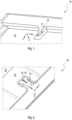
- Figure 2 shows a top view of the system 10 for fixing the loading floor with the loading floor 11 placed on the loading floor support 12 with the shaped element 14 locked onto the locking element 13.
- the locking element 13, which is designed as a projection 15, is typically manufactured on the loading floor support 12 using an injection molding process.
- the locking element 13 is designed as a locking hook or barb.
- the locking element 13 has an end near the loading floor support and an end remote from the loading floor support, with the locking element 13 having a T-shaped configuration at its end remote from the loading floor support.
- the shaped element 14 is embossed into the loading floor 11.
- the shaped element 14 is embossed into the loading floor 11 in such a way that the loading floor 11 is at least partially interrupted.
- the shaped element 14 is designed, in particular, as a click closure.
- the shaped element 14 has a T-shaped configuration in the X direction.
- the shaped element 14 is generally designed to correspond geometrically to the locking element 13 in order to form a sliding/click closure or a sliding/plug closure.
- the loading floor 11 with the shaped element 14 is designed to be slid or clicked onto the loading floor support 12. During the sliding process, the shaped element 14 locks onto the locking element 13 of the loading floor support 12 in both the X and Z directions.
- Figure 3 shows a longitudinal section through the system 10 for fixing the loading floor with the shaped element 14 and the locking element 13 locked into the shaped element 14.
- the locking element 13 is formed on the loading floor support 12.
- the locking element 13 is designed as a projection 15, in particular as a locking hook.
- the locking element 13 also has a circumferential Z support or a deflection 16, which extends from the projection 15 at an end of the locking element 13 remote from the loading floor support, parallel to the loading floor support 12.
- the shaped element 14 is formed in the loading floor 11, wherein the shaped element 14 is U-shaped, wherein the U-shape in the shaped element 14 forms a locking surface 17 that is formed perpendicular to a contact surface of the loading floor 11 with a loading floor support 12 (not shown).
- the locking surface 17 is rounded or beveled.
- the shaped element 14 is designed to correspond to the geometric shape of the locking element 13.
- the loading floor 11 with the shaped element 14 is shown attached to the loading floor support 12 with the locking element 13.
- the locking element 13 is configured to lock in the X direction by sliding the shaped element 14 on and to lock in the Z direction by locking a deflection 16 or a Z support on the beveled locking surface of the U-shaped shaped element 14.
- Figure 4 shows a top view of the system 10 for securing the loading floor with the shaped element 14 and the locking element 13, which is engaged in the shaped element 14 and is designed as a projection 15.
- the shaped element 14 is designed as the female part of the sliding/plug-in closure, while the locking element is designed as the male part of the sliding/plug-in closure.
- the loading floor 11 with the shaped element 14 is designed to hook onto the locking element 13 when pushed onto the loading floor support 12 and to form a locking connection, in particular a sliding/plug-in connection, both in the X direction and in the Z direction.
- Figure 5 shows a perspective view of the locking element 13 in the locked state in the shaped element 14 of the system 10 for securing the loading floor.
- the loading floor 11 with the shaped element 14 is pushed or locked onto the loading floor support 12 with the locking element 13 and is thus locked in both the X direction and the Z direction.
- the shaped element 14 is pushed onto the locking element 13 so that the at least one projection 15 of the locking element 13 engages and locks into the at least one recess of the shaped element 14.
- Figure 6 shows a schematic side view of the system 10 for securing the loading floor with the loading floor 11, the shaped element 14, and the locking element 13 of the loading floor support 12.
- the locking element 13 locks onto a rounded or beveled surface of the shaped element 14, a locking surface 17, both in the X direction and in the Z direction.
- the locking element 14 is formed from the projection 15 and the deflection 16.
Landscapes
- Engineering & Computer Science (AREA)
- Mechanical Engineering (AREA)
- Chemical & Material Sciences (AREA)
- Combustion & Propulsion (AREA)
- Transportation (AREA)
- Passenger Equipment (AREA)
- Connection Of Plates (AREA)
- Vehicle Step Arrangements And Article Storage (AREA)
- Floor Finish (AREA)
- Seats For Vehicles (AREA)
Claims (6)
- Système (10) de fixation de plancher de chargement dans un véhicule automobile, comprenant un support de plancher de chargement (12) et au moins un plancher de chargement (11), dans lequel le support de plancher de chargement (12) comprend au moins un élément d'encliquetage (13), dans lequel le plancher de chargement (11) présente au moins un élément moulé (14) qui est conçu pour l'encliquetage sur l'au moins un élément d'encliquetage (13) du support de plancher de chargement (12), dans lequel le système (10) est conçu sur la base de l'encliquetage afin de bloquer le plancher de chargement (11) sur le support de plancher de chargement (12), et dans lequel l'élément d'encliquetage (13) est formé comme élément à clic qui est conçu afin d'être compressible par l'élément moulé (14) du plancher de chargement (11) lorsque le plancher de chargement (11) est poussé et de se déployer lorsque le processus de poussée atteint une position finale et de bloquer ainsi le plancher de chargement (11), dans lequel le système (10) est conçu afin de bloquer le plancher de chargement (11) sur le support de plancher de chargement (12) dans un sens X et dans un sens Z, caractérisé en ce que l'élément d'encliquetage (13) est formé comme un crochet, en particulier un crochet d'encliquetage.
- Système (10) selon la revendication 1, caractérisé en ce que l'élément moulé (14) est formé de manière gaufrée d'un seul tenant dans le plancher de chargement (11).
- Système (10) selon la revendication 2, caractérisé en ce que l'élément moulé (14) est formé en U, dans lequel le U forme dans l'élément moulé (14) une surface d'encliquetage (17) qui est formée perpendiculairement à une surface de contact du plancher de chargement (11) avec le support de plancher de chargement (12).
- Système (10) selon la revendication 3, caractérisé en ce que la surface d'encliquetage (17) est formée au moins par endroits de manière arrondie ou chanfreinée.
- Système (10) selon la revendication 1, caractérisé en ce que l'élément d'encliquetage (13) est conçu afin de s'encliqueter au moins partiellement derrière ou sur l'élément moulé (14).
- Système (10) selon l'une quelconque des revendications précédentes, caractérisé en ce que l'élément moulé (14) est formé de manière correspondante géométriquement à l'élément d'encliquetage (13).
Applications Claiming Priority (2)
| Application Number | Priority Date | Filing Date | Title |
|---|---|---|---|
| DE102020116798.9A DE102020116798B4 (de) | 2020-06-25 | 2020-06-25 | Ladebodenfixierungssystem |
| PCT/EP2021/058834 WO2021259531A1 (fr) | 2020-06-25 | 2021-04-06 | Système de fixation de plancher de chargement |
Publications (2)
| Publication Number | Publication Date |
|---|---|
| EP4172003A1 EP4172003A1 (fr) | 2023-05-03 |
| EP4172003B1 true EP4172003B1 (fr) | 2025-06-18 |
Family
ID=75539289
Family Applications (1)
| Application Number | Title | Priority Date | Filing Date |
|---|---|---|---|
| EP21719060.2A Active EP4172003B1 (fr) | 2020-06-25 | 2021-04-06 | Système de fixation de plancher de chargement |
Country Status (5)
| Country | Link |
|---|---|
| US (1) | US12358440B2 (fr) |
| EP (1) | EP4172003B1 (fr) |
| CN (1) | CN115379967B (fr) |
| DE (1) | DE102020116798B4 (fr) |
| WO (1) | WO2021259531A1 (fr) |
Families Citing this family (2)
| Publication number | Priority date | Publication date | Assignee | Title |
|---|---|---|---|---|
| DE102020116798B4 (de) * | 2020-06-25 | 2023-08-31 | Audi Aktiengesellschaft | Ladebodenfixierungssystem |
| FR3136425B1 (fr) * | 2022-06-09 | 2024-04-26 | Psa Automobiles Sa | Support latéral de panneau de plancher de coffre. |
Family Cites Families (22)
| Publication number | Priority date | Publication date | Assignee | Title |
|---|---|---|---|---|
| FR2745523B1 (fr) * | 1996-03-04 | 1998-05-22 | Manducher Sa | Moule de formage pour un empilement composite |
| DE102007010927A1 (de) * | 2007-03-05 | 2008-09-11 | GM Global Technology Operations, Inc., Detroit | Ladebodenanordnung |
| DE102009032892A1 (de) * | 2009-07-13 | 2011-01-20 | Volkswagen Ag | Vorrichtung mit einem höhenverstellbaren Ladeboden für einen Laderaum eines Fahrzeuges sowie Halteeinrichtung für einen höhenverstellbaren Ladeboden eines Fahrzeuges |
| DE102010056400A1 (de) | 2010-12-28 | 2012-06-28 | GM Global Technology Operations LLC | Ladeboden, Ablagevorrichtung, Höhenverstellsystem, Laderaum und Kraftfahrtzeug, sowie Verfahren hierzu |
| DE102011118179A1 (de) * | 2011-11-10 | 2013-05-16 | GM Global Technology Operations LLC (n. d. Gesetzen des Staates Delaware) | Sitzbefestigung |
| US8859074B2 (en) * | 2012-04-23 | 2014-10-14 | Global Ip Holdings, Llc | Sandwich-type, generally planar, structural member having an attachment feature and assembly utilizing same |
| US8808830B2 (en) * | 2012-04-23 | 2014-08-19 | Global Ip Holdings, Llc | Sandwich-type, structural, composite component having a cut-out feature with a substantially hidden core, assembly utilizing same and panel for use in a vehicle load floor assembly |
| DE102013018037A1 (de) | 2013-12-02 | 2015-06-03 | GM Global Technology Operations LLC (n. d. Ges. d. Staates Delaware) | Laderaumanordnung für ein Fahrzeug und Fahrzeug mit der Laderaumanordnung |
| DE102014100600A1 (de) * | 2014-01-21 | 2015-07-23 | Hella Kgaa Hueck & Co. | Kunststoffabschlussscheibe eines Scheinwerfers mit außenseitig angeordneter Trägerleiste |
| US9376147B2 (en) * | 2014-03-07 | 2016-06-28 | Fca Us Llc | Two-stage cargo floor |
| DE102014015030B4 (de) | 2014-10-09 | 2020-11-05 | Audi Ag | Vorrichtung zur Abdeckung eines Kofferraumbodens |
| DE202015008707U1 (de) | 2015-12-18 | 2017-03-21 | GM Global Technology Operations LLC (n. d. Ges. d. Staates Delaware) | Kraftfahrzeug mit einer Vorrichtung zum Halten eines Ladebodens |
| DE102016002885A1 (de) * | 2016-03-09 | 2017-09-14 | GM Global Technology Operations LLC (n. d. Gesetzen des Staates Delaware) | Kraftfahrzeug mit Laderaumboden |
| US9908475B2 (en) * | 2016-07-13 | 2018-03-06 | GM Global Technology Operations LLC | Securement system for a storage area of a vehicle |
| US9868405B1 (en) * | 2016-07-22 | 2018-01-16 | Caterpillar Inc. | Bed liner fastening system and method |
| DE102016013687A1 (de) | 2016-11-16 | 2018-05-17 | GM Global Technology Operations LLC (n. d. Gesetzen des Staates Delaware) | Befestigungsvorrichtung zur Befestigung einer Ladebodenabstützung einer Kofferraumandordnung an einer Seitenwand der Kofferraumanordnung für ein Fahrzeug. Kofferraumanordnung mit der Befestigungsvorrichtung, der Seitenwand und der Ladebodenabstützung und Fahrzeug mit der Kofferraumanordnung |
| DE202017001105U1 (de) | 2017-02-28 | 2018-05-29 | GM Global Technology Operations LLC (n. d. Ges. d. Staates Delaware) | Abdeckelement für einen Laderaum eines Kraftfahrzeuges |
| US10196000B2 (en) * | 2017-05-15 | 2019-02-05 | Ford Global Technologies, Llc | Vehicle trunk |
| US10513225B2 (en) * | 2018-02-13 | 2019-12-24 | GM Global Technology Operations LLC | Motor vehicle with height adjustable floor |
| US11110969B2 (en) * | 2020-01-10 | 2021-09-07 | Caterpillar Inc. | Quick release floor panel system for a work machine |
| DE102020116798B4 (de) * | 2020-06-25 | 2023-08-31 | Audi Aktiengesellschaft | Ladebodenfixierungssystem |
| US11420565B2 (en) * | 2020-12-18 | 2022-08-23 | Ford Global Technologies, Llc | Cargo divider assembly for a vehicle |
-
2020
- 2020-06-25 DE DE102020116798.9A patent/DE102020116798B4/de active Active
-
2021
- 2021-04-06 WO PCT/EP2021/058834 patent/WO2021259531A1/fr not_active Ceased
- 2021-04-06 US US17/912,582 patent/US12358440B2/en active Active
- 2021-04-06 EP EP21719060.2A patent/EP4172003B1/fr active Active
- 2021-04-06 CN CN202180027491.7A patent/CN115379967B/zh active Active
Also Published As
| Publication number | Publication date |
|---|---|
| DE102020116798B4 (de) | 2023-08-31 |
| EP4172003A1 (fr) | 2023-05-03 |
| WO2021259531A1 (fr) | 2021-12-30 |
| CN115379967B (zh) | 2026-01-02 |
| DE102020116798A1 (de) | 2021-12-30 |
| US12358440B2 (en) | 2025-07-15 |
| CN115379967A (zh) | 2022-11-22 |
| US20230211742A1 (en) | 2023-07-06 |
Similar Documents
| Publication | Publication Date | Title |
|---|---|---|
| DE29724486U1 (de) | Steckverbinder mit Sekundärverriegelung | |
| EP4172003B1 (fr) | Système de fixation de plancher de chargement | |
| DE60214426T2 (de) | Kraftstofftank für ein kraftfahrzeug | |
| EP1704069A2 (fr) | Dispositif de verrouillage de siege de vehicule | |
| DE19825439C2 (de) | Entnehmbarer Fahrzeugsitz | |
| EP0790153A1 (fr) | Dispositif de fixation d'un module de sac de sécurité gonflable | |
| DE102015110297A1 (de) | Systeme und verfahren zur elastisch gemittelten ausrichtung | |
| EP3652450B1 (fr) | Connecteur, système composé d'un connecteur et d'une tige d'encliquetage contenant une tête d'un deuxième composant, procédé utilisant un tel système | |
| DE102017125771A1 (de) | Fahrzeugkomponenten-Befestiger mit verbesserter Vorverrastung | |
| EP2531379B1 (fr) | Module pour fixer un élément d'un véhicule | |
| EP1252037B1 (fr) | Dispositif d'ancrage pour siege de vehicule pouvant etre monte et demonte sans outil | |
| EP2347070B1 (fr) | Poignée pour véhicule automobile | |
| EP1297232A1 (fr) | Fermeture de portiere de vehicule automobile | |
| DE102011003052A1 (de) | Betätigungsvorrichtung für eine Verriegelungseinrichtung einer Verstellvorrichtung eines Kraftfahrzeugsitzes | |
| DE102021124002B4 (de) | Kindersicherheitssitz mit kopfstütze | |
| DE202012104145U1 (de) | Vorrichtung zum Verbinden eines Schlossträgers mit einem Funktionsträger einer Kraftfahrzeugtür | |
| DE10034019A1 (de) | Befestigungsvorrichtung, insbesondere für einen Fahrzeugsitz | |
| DE20116911U1 (de) | Schaumteil, insbesondere zur Verwendung als Polsterelement bei der Herstellung von Fahrzeugsitzen | |
| EP3774449B1 (fr) | Système de maintien destiné à fixer un écran à un élément porteur d'un véhicule, système d'écran | |
| DE102011050540B4 (de) | Kopfstütze für Kraftfahrzeugsitz | |
| DE102018209007A1 (de) | Vorrichtung und Verfahren zur Verwendung einer Vorrichtung zum Platzieren von Komponenten eines Systems | |
| DE10110480C2 (de) | Vorrichtung zur Fernbetätigung mindestens eines verstellbaren Kraftfahrzeugsitzbauteils | |
| DE102019208534B4 (de) | Kopfstützenhalterung und Kopfstützenanordnung | |
| DE102022118735A1 (de) | Befestigungsvorrichtung | |
| DE102021204425A1 (de) | Fahrzeugtür und Montageverfahren dafür |
Legal Events
| Date | Code | Title | Description |
|---|---|---|---|
| STAA | Information on the status of an ep patent application or granted ep patent |
Free format text: STATUS: UNKNOWN |
|
| STAA | Information on the status of an ep patent application or granted ep patent |
Free format text: STATUS: THE INTERNATIONAL PUBLICATION HAS BEEN MADE |
|
| PUAI | Public reference made under article 153(3) epc to a published international application that has entered the european phase |
Free format text: ORIGINAL CODE: 0009012 |
|
| STAA | Information on the status of an ep patent application or granted ep patent |
Free format text: STATUS: REQUEST FOR EXAMINATION WAS MADE |
|
| 17P | Request for examination filed |
Effective date: 20230125 |
|
| AK | Designated contracting states |
Kind code of ref document: A1 Designated state(s): AL AT BE BG CH CY CZ DE DK EE ES FI FR GB GR HR HU IE IS IT LI LT LU LV MC MK MT NL NO PL PT RO RS SE SI SK SM TR |
|
| P01 | Opt-out of the competence of the unified patent court (upc) registered |
Effective date: 20230529 |
|
| DAV | Request for validation of the european patent (deleted) | ||
| DAX | Request for extension of the european patent (deleted) | ||
| STAA | Information on the status of an ep patent application or granted ep patent |
Free format text: STATUS: EXAMINATION IS IN PROGRESS |
|
| 17Q | First examination report despatched |
Effective date: 20241014 |
|
| GRAP | Despatch of communication of intention to grant a patent |
Free format text: ORIGINAL CODE: EPIDOSNIGR1 |
|
| STAA | Information on the status of an ep patent application or granted ep patent |
Free format text: STATUS: GRANT OF PATENT IS INTENDED |
|
| INTG | Intention to grant announced |
Effective date: 20250408 |
|
| GRAS | Grant fee paid |
Free format text: ORIGINAL CODE: EPIDOSNIGR3 |
|
| GRAA | (expected) grant |
Free format text: ORIGINAL CODE: 0009210 |
|
| STAA | Information on the status of an ep patent application or granted ep patent |
Free format text: STATUS: THE PATENT HAS BEEN GRANTED |
|
| AK | Designated contracting states |
Kind code of ref document: B1 Designated state(s): AL AT BE BG CH CY CZ DE DK EE ES FI FR GB GR HR HU IE IS IT LI LT LU LV MC MK MT NL NO PL PT RO RS SE SI SK SM TR |
|
| REG | Reference to a national code |
Ref country code: GB Ref legal event code: FG4D Free format text: NOT ENGLISH |
|
| REG | Reference to a national code |
Ref country code: CH Ref legal event code: EP |
|
| REG | Reference to a national code |
Ref country code: DE Ref legal event code: R096 Ref document number: 502021007783 Country of ref document: DE |
|
| REG | Reference to a national code |
Ref country code: CH Ref legal event code: EP |
|
| REG | Reference to a national code |
Ref country code: IE Ref legal event code: FG4D Free format text: LANGUAGE OF EP DOCUMENT: GERMAN |
|
| PG25 | Lapsed in a contracting state [announced via postgrant information from national office to epo] |
Ref country code: FI Free format text: LAPSE BECAUSE OF FAILURE TO SUBMIT A TRANSLATION OF THE DESCRIPTION OR TO PAY THE FEE WITHIN THE PRESCRIBED TIME-LIMIT Effective date: 20250618 |
|
| REG | Reference to a national code |
Ref country code: LT Ref legal event code: MG9D |
|
| PG25 | Lapsed in a contracting state [announced via postgrant information from national office to epo] |
Ref country code: NO Free format text: LAPSE BECAUSE OF FAILURE TO SUBMIT A TRANSLATION OF THE DESCRIPTION OR TO PAY THE FEE WITHIN THE PRESCRIBED TIME-LIMIT Effective date: 20250918 Ref country code: GR Free format text: LAPSE BECAUSE OF FAILURE TO SUBMIT A TRANSLATION OF THE DESCRIPTION OR TO PAY THE FEE WITHIN THE PRESCRIBED TIME-LIMIT Effective date: 20250919 |
|
| PG25 | Lapsed in a contracting state [announced via postgrant information from national office to epo] |
Ref country code: BG Free format text: LAPSE BECAUSE OF FAILURE TO SUBMIT A TRANSLATION OF THE DESCRIPTION OR TO PAY THE FEE WITHIN THE PRESCRIBED TIME-LIMIT Effective date: 20250618 |
|
| PG25 | Lapsed in a contracting state [announced via postgrant information from national office to epo] |
Ref country code: HR Free format text: LAPSE BECAUSE OF FAILURE TO SUBMIT A TRANSLATION OF THE DESCRIPTION OR TO PAY THE FEE WITHIN THE PRESCRIBED TIME-LIMIT Effective date: 20250618 |
|
| PG25 | Lapsed in a contracting state [announced via postgrant information from national office to epo] |
Ref country code: RS Free format text: LAPSE BECAUSE OF FAILURE TO SUBMIT A TRANSLATION OF THE DESCRIPTION OR TO PAY THE FEE WITHIN THE PRESCRIBED TIME-LIMIT Effective date: 20250918 |
|
| REG | Reference to a national code |
Ref country code: NL Ref legal event code: MP Effective date: 20250618 |
|
| PG25 | Lapsed in a contracting state [announced via postgrant information from national office to epo] |
Ref country code: LV Free format text: LAPSE BECAUSE OF FAILURE TO SUBMIT A TRANSLATION OF THE DESCRIPTION OR TO PAY THE FEE WITHIN THE PRESCRIBED TIME-LIMIT Effective date: 20250618 |
|
| PG25 | Lapsed in a contracting state [announced via postgrant information from national office to epo] |
Ref country code: NL Free format text: LAPSE BECAUSE OF FAILURE TO SUBMIT A TRANSLATION OF THE DESCRIPTION OR TO PAY THE FEE WITHIN THE PRESCRIBED TIME-LIMIT Effective date: 20250618 |
|
| PG25 | Lapsed in a contracting state [announced via postgrant information from national office to epo] |
Ref country code: PT Free format text: LAPSE BECAUSE OF FAILURE TO SUBMIT A TRANSLATION OF THE DESCRIPTION OR TO PAY THE FEE WITHIN THE PRESCRIBED TIME-LIMIT Effective date: 20251020 |
|
| PG25 | Lapsed in a contracting state [announced via postgrant information from national office to epo] |
Ref country code: IS Free format text: LAPSE BECAUSE OF FAILURE TO SUBMIT A TRANSLATION OF THE DESCRIPTION OR TO PAY THE FEE WITHIN THE PRESCRIBED TIME-LIMIT Effective date: 20251018 |
|
| PG25 | Lapsed in a contracting state [announced via postgrant information from national office to epo] |
Ref country code: SM Free format text: LAPSE BECAUSE OF FAILURE TO SUBMIT A TRANSLATION OF THE DESCRIPTION OR TO PAY THE FEE WITHIN THE PRESCRIBED TIME-LIMIT Effective date: 20250618 |
|
| PG25 | Lapsed in a contracting state [announced via postgrant information from national office to epo] |
Ref country code: CZ Free format text: LAPSE BECAUSE OF FAILURE TO SUBMIT A TRANSLATION OF THE DESCRIPTION OR TO PAY THE FEE WITHIN THE PRESCRIBED TIME-LIMIT Effective date: 20250618 |
|
| PG25 | Lapsed in a contracting state [announced via postgrant information from national office to epo] |
Ref country code: PL Free format text: LAPSE BECAUSE OF FAILURE TO SUBMIT A TRANSLATION OF THE DESCRIPTION OR TO PAY THE FEE WITHIN THE PRESCRIBED TIME-LIMIT Effective date: 20250618 |
|
| PG25 | Lapsed in a contracting state [announced via postgrant information from national office to epo] |
Ref country code: EE Free format text: LAPSE BECAUSE OF FAILURE TO SUBMIT A TRANSLATION OF THE DESCRIPTION OR TO PAY THE FEE WITHIN THE PRESCRIBED TIME-LIMIT Effective date: 20250618 |
|
| PG25 | Lapsed in a contracting state [announced via postgrant information from national office to epo] |
Ref country code: SK Free format text: LAPSE BECAUSE OF FAILURE TO SUBMIT A TRANSLATION OF THE DESCRIPTION OR TO PAY THE FEE WITHIN THE PRESCRIBED TIME-LIMIT Effective date: 20250618 |
|
| PG25 | Lapsed in a contracting state [announced via postgrant information from national office to epo] |
Ref country code: ES Free format text: LAPSE BECAUSE OF FAILURE TO SUBMIT A TRANSLATION OF THE DESCRIPTION OR TO PAY THE FEE WITHIN THE PRESCRIBED TIME-LIMIT Effective date: 20250618 |