EP4172003B1 - Loading floor fixation system - Google Patents
Loading floor fixation system Download PDFInfo
- Publication number
- EP4172003B1 EP4172003B1 EP21719060.2A EP21719060A EP4172003B1 EP 4172003 B1 EP4172003 B1 EP 4172003B1 EP 21719060 A EP21719060 A EP 21719060A EP 4172003 B1 EP4172003 B1 EP 4172003B1
- Authority
- EP
- European Patent Office
- Prior art keywords
- loading floor
- locking
- shaped
- locking element
- shaped element
- Prior art date
- Legal status (The legal status is an assumption and is not a legal conclusion. Google has not performed a legal analysis and makes no representation as to the accuracy of the status listed.)
- Active
Links
Images


Classifications
-
- B—PERFORMING OPERATIONS; TRANSPORTING
- B60—VEHICLES IN GENERAL
- B60R—VEHICLES, VEHICLE FITTINGS, OR VEHICLE PARTS, NOT OTHERWISE PROVIDED FOR
- B60R13/00—Elements for body-finishing, identifying, or decorating; Arrangements or adaptations for advertising purposes
- B60R13/01—Liners for load platforms or load compartments
- B60R13/011—Liners for load platforms or load compartments for internal load compartments, e.g. car trunks
-
- B—PERFORMING OPERATIONS; TRANSPORTING
- B60—VEHICLES IN GENERAL
- B60R—VEHICLES, VEHICLE FITTINGS, OR VEHICLE PARTS, NOT OTHERWISE PROVIDED FOR
- B60R13/00—Elements for body-finishing, identifying, or decorating; Arrangements or adaptations for advertising purposes
- B60R13/01—Liners for load platforms or load compartments
-
- B—PERFORMING OPERATIONS; TRANSPORTING
- B62—LAND VEHICLES FOR TRAVELLING OTHERWISE THAN ON RAILS
- B62D—MOTOR VEHICLES; TRAILERS
- B62D25/00—Superstructure or monocoque structure sub-units; Parts or details thereof not otherwise provided for
- B62D25/20—Floors or bottom sub-units
Definitions
- the present invention relates to a system for fixing the loading floor in a motor vehicle, comprising a loading floor support and at least one loading floor, wherein the loading floor support comprises at least one locking element.
- the document shows DE 10 2010 056 400 A1 a loading floor for a loading space, which comprises a loading floor plate which has a tooth-shaped profile on at least one side for engagement in a complementary motor vehicle-side holding profile, and a method for adjusting a loading space volume are known.
- a fastening device for attaching a loading floor support of a trunk assembly to a side wall of the trunk assembly for a vehicle is known.
- the side wall has a firmly integrated locking interface that can be locked into a counter-locking interface of a loading floor support.
- a motor vehicle with a device for holding a loading floor comprises a rear loading space with a device for holding the loading floor, which is manufactured in one piece with a trim part and passes through a through opening in the loading floor.
- the storage container includes a housing having a collar, a bottom surface, and a plurality of side surfaces extending between the collar and the bottom surface.
- the side surfaces each define a top surface and an intermediate surface extending continuously around an inner perimeter of the housing and oriented parallel to the collar and the bottom surface.
- a lid is configured to rest on the top surface in a first storage position when the lid has a first orientation and to rest on the intermediate surface in a second storage position when the lid has a second orientation, the second orientation being rotated 90 degrees relative to the first orientation.
- a device for covering one or more storage compartments in the floor of a motor vehicle trunk comprises a trunk mat.
- the trunk mat is two-part and flexible at the section. It can be connected via fastening elements to a loading box attached to the body and provided with storage compartments.
- the object of the present invention is to provide a system that enables easier to produce, more cost-effective and improved loading floor fixation.
- the subject matter of the present invention is a system for securing the loading floor in a motor vehicle, comprising a loading floor support and at least one loading floor, wherein the loading floor support comprises at least one locking element, wherein the loading floor has at least one shaped element which is designed to lock onto the at least one locking element of the loading floor support, wherein the system is designed to lock the loading floor on the loading floor support based on the locking, and wherein the locking element is designed as a click element which is designed to be compressible by the shaped element of the loading floor when the loading floor is pushed on and to unfold when an end position of the sliding-on process is reached and thereby lock the loading floor, wherein the system is designed to lock the loading floor on the loading floor support in an X direction and in a Z direction, wherein the locking element is designed as a hook, in particular a locking hook.
- the loading floor has at least one shaped element that is designed to latch onto the at least one locking element of the loading floor support, wherein the system is designed to lock the loading floor onto the loading floor support based on the latching.
- the loading floor in particular the shaped element, is designed and configured such that the loading floor can be fixed or locked to at least one further component of the motor vehicle, in particular the locking element of the loading floor support.
- the system is generally arranged in the area of a rear seat bench of a motor vehicle. The system offers the advantage that the loading floor can be secured without additional attachments.
- the locking element is typically applied to the loading floor support using an injection molding process.
- the locking element is designed as the male part of a sliding/plug-in closure.
- the locking element is designed as a projection that is designed to engage the molded element when the loading floor is slid onto the loading floor support.
- the locking element is designed as a click element that is configured to be compressible by the shaped element of the loading floor when the loading floor is pushed open and to unfold upon reaching an end position of the sliding-open process, thereby locking the loading floor.
- the locking element is generally designed to be compressible, with the locking element having at least one slot that allows the locking element to be compressed.
- the locking element generally extends at a right angle to the loading floor support and is between 1 mm and 50 mm, in particular between 20 mm and 30 mm, wide.
- the locking element has at least one slot in the center.
- the slot is generally formed at a right angle to the loading floor support and has a width between 1 mm and 5 mm, in particular between 3 mm and 4 mm.
- the shaped element is generally designed to correspond to the geometry of the locking element.
- the shaped element is designed as the female part of the sliding/plug-in closure.
- the shaped element has at least one recess configured to accommodate the at least one projection of the locking element, the male part of the sliding/plug-in closure.
- the shaped element of the loading floor offers the advantage that it can be easily implemented in the manufacturing process of the loading floor and thus does not require any special processes.
- the molded element is typically embossed into the loading floor to a depth of between 10 mm and 50 mm, in particular between 30 mm and 40 mm.
- the molded element has a width of between 10 mm and 50 mm, in particular between 30 mm and 45 mm.
- the system is designed to lock the loading floor onto the loading floor support in an X-direction and/or in a Z-direction.
- the system is designed such that the loading floor can be pushed onto the locking element of the loading floor support with the at least one shaped element. By pushing the loading floor onto the The loading floor support locks the locking element with the projection and the deflection on the shaped element in both the X-direction and the Z-direction.
- the system offers the advantage that the integrated geometry eliminates the need for additional components, and the loading floor supports an X- and Z-direction of the rear locking mechanism. This allows the loading floor to be locked in both the X and Z directions.
- the molded element is formed as a single piece and embossed into the loading floor.
- the molded element can be embossed into the loading floor during the pressing process.
- the insertion of the molded element does not require a separate process, allowing the molded element to be implemented during the loading floor manufacturing process.
- the shaped element is U-shaped, with the U-shape forming a locking surface in the shaped element that is perpendicular to a contact surface of the loading floor with the loading floor support.
- the shaped element is formed as a recess embossed into the loading floor.
- the U-shaped design of the shaped element offers the advantage that the locking element can be inserted laterally into the shaped element.
- the locking surface is rounded or beveled at least in some areas.
- the locking surface is rounded or beveled at least in some areas.
- the rounded or beveled locking surface of the shaped element offers the advantage that the locking element can engage or engage behind the rounded or angled locking surface of the shaped element.
- the engagement or engagement of the locking element in the area of the rounded or angled locking surface of the shaped element leads to a locking of the locking element on the at least one rounded or angled locking surface of the shaped element.
- the locking element typically has a deflection at the end of the projection facing the loading floor, which is designed to engage or rest on the locking surface of the U-shaped element.
- the deflection is designed as an extension of the projection, which is substantially parallel to the loading floor support.
- the deflection is angled from the projection.
- the deflection is T-shaped.
- the locking element is designed as a hook, particularly a locking hook.
- the locking element is typically applied to the loading floor support using an injection molding process.
- the locking element has an end near the loading floor support and an end far from the loading floor support.
- the locking element is T-shaped in the X direction at its end far from the loading floor support and configured as a circumferential Z-support surface in the Z direction.
- the Z-support surface corresponds to the deflection of the locking element.
- the locking element is configured to latch and/or engage at least partially behind or onto the shaped element.
- a respective locking element is generally configured to engage a respective shaped element by means of latching forces.
- the shaped element is geometrically designed to correspond to the locking element.
- the shaped element and the locking element together generally form the sliding/plug-in closure.
- the shaped element is a female part of the sliding/plug-in closure, and the locking element is a male part of the sliding/plug-in closure.
- the loading floor with the shaped element is designed to be slidable and clickable onto the loading floor support.
- the system includes a loading floor for securing the loading floor.
- the loading floor has at least one shaped element which is embossed into the loading floor and is designed and configured to receive at least one locking element.
- the locking element is typically manufactured on the loading floor support using an injection molding process.
- the locking element is designed as a locking hook or barb.
- the locking element has at least one slot, which allows the locking element to be compressed when inserted into the molded element.
- the shaped element is embossed into the loading floor.
- the shaped element is embossed into the loading floor in such a way that the loading floor is at least partially interrupted.
- the shaped element has at least one recess designed to accommodate the projection of the locking element.
- the recess of the shaped element is, for example, T-shaped.
- the shaped element is designed as the female part of a sliding/click closure.
- the locking element is designed as the male part of a sliding/click closure.
- a first step the loading floor is pressed.
- a further step which takes place simultaneously with the first step, at least one mold element is embossed into the loading floor during the pressing process.
- the locking element is produced on the loading floor support by means of an injection molding process.
- Figure 1 shows a loading floor 11 with a shaped element 14 of the system 10 for securing the loading floor.
- the loading floor 11 has a U-shaped shaped element 14.
- the U-shaped shaped element 14 is embossed into the loading floor 11.
- the U-shaped shaped element 14 is formed in the Z-direction in the loading floor 11.
- the U-shaped configuration of the shaped element 14 allows for the insertion of a locking element (not shown).
- the shaped element 14 is U-shaped, with the U-shape forming a locking surface 17 in the shaped element 14, which is perpendicular to a contact surface of the loading floor 11 with a loading floor support (not shown).
- the locking surface 17 is rounded or beveled.
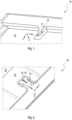
- Figure 2 shows a top view of the system 10 for fixing the loading floor with the loading floor 11 placed on the loading floor support 12 with the shaped element 14 locked onto the locking element 13.
- the locking element 13, which is designed as a projection 15, is typically manufactured on the loading floor support 12 using an injection molding process.
- the locking element 13 is designed as a locking hook or barb.
- the locking element 13 has an end near the loading floor support and an end remote from the loading floor support, with the locking element 13 having a T-shaped configuration at its end remote from the loading floor support.
- the shaped element 14 is embossed into the loading floor 11.
- the shaped element 14 is embossed into the loading floor 11 in such a way that the loading floor 11 is at least partially interrupted.
- the shaped element 14 is designed, in particular, as a click closure.
- the shaped element 14 has a T-shaped configuration in the X direction.
- the shaped element 14 is generally designed to correspond geometrically to the locking element 13 in order to form a sliding/click closure or a sliding/plug closure.
- the loading floor 11 with the shaped element 14 is designed to be slid or clicked onto the loading floor support 12. During the sliding process, the shaped element 14 locks onto the locking element 13 of the loading floor support 12 in both the X and Z directions.
- Figure 3 shows a longitudinal section through the system 10 for fixing the loading floor with the shaped element 14 and the locking element 13 locked into the shaped element 14.
- the locking element 13 is formed on the loading floor support 12.
- the locking element 13 is designed as a projection 15, in particular as a locking hook.
- the locking element 13 also has a circumferential Z support or a deflection 16, which extends from the projection 15 at an end of the locking element 13 remote from the loading floor support, parallel to the loading floor support 12.
- the shaped element 14 is formed in the loading floor 11, wherein the shaped element 14 is U-shaped, wherein the U-shape in the shaped element 14 forms a locking surface 17 that is formed perpendicular to a contact surface of the loading floor 11 with a loading floor support 12 (not shown).
- the locking surface 17 is rounded or beveled.
- the shaped element 14 is designed to correspond to the geometric shape of the locking element 13.
- the loading floor 11 with the shaped element 14 is shown attached to the loading floor support 12 with the locking element 13.
- the locking element 13 is configured to lock in the X direction by sliding the shaped element 14 on and to lock in the Z direction by locking a deflection 16 or a Z support on the beveled locking surface of the U-shaped shaped element 14.
- Figure 4 shows a top view of the system 10 for securing the loading floor with the shaped element 14 and the locking element 13, which is engaged in the shaped element 14 and is designed as a projection 15.
- the shaped element 14 is designed as the female part of the sliding/plug-in closure, while the locking element is designed as the male part of the sliding/plug-in closure.
- the loading floor 11 with the shaped element 14 is designed to hook onto the locking element 13 when pushed onto the loading floor support 12 and to form a locking connection, in particular a sliding/plug-in connection, both in the X direction and in the Z direction.
- Figure 5 shows a perspective view of the locking element 13 in the locked state in the shaped element 14 of the system 10 for securing the loading floor.
- the loading floor 11 with the shaped element 14 is pushed or locked onto the loading floor support 12 with the locking element 13 and is thus locked in both the X direction and the Z direction.
- the shaped element 14 is pushed onto the locking element 13 so that the at least one projection 15 of the locking element 13 engages and locks into the at least one recess of the shaped element 14.
- Figure 6 shows a schematic side view of the system 10 for securing the loading floor with the loading floor 11, the shaped element 14, and the locking element 13 of the loading floor support 12.
- the locking element 13 locks onto a rounded or beveled surface of the shaped element 14, a locking surface 17, both in the X direction and in the Z direction.
- the locking element 14 is formed from the projection 15 and the deflection 16.
Landscapes
- Engineering & Computer Science (AREA)
- Mechanical Engineering (AREA)
- Chemical & Material Sciences (AREA)
- Combustion & Propulsion (AREA)
- Transportation (AREA)
- Passenger Equipment (AREA)
- Connection Of Plates (AREA)
- Vehicle Step Arrangements And Article Storage (AREA)
- Floor Finish (AREA)
- Seats For Vehicles (AREA)
Description
Die vorliegende Erfindung betrifft ein System zur Ladebodenfixierung in einem Kraftfahrzeug, umfassend eine Ladebodenauflage und zumindest einen Ladeboden, wobei die Ladebodenauflage zumindest ein Rastelement umfasst.The present invention relates to a system for fixing the loading floor in a motor vehicle, comprising a loading floor support and at least one loading floor, wherein the loading floor support comprises at least one locking element.
Im Stand der Technik sind Halteprofile für Ladeböden bekannt.Retaining profiles for loading floors are known in the state of the art.
So sind aus dem Dokument
Aus dem Dokument
Aus dem Dokument
Dokument
Aus dem Dokument
Im Stand der Technik werden zur Fixierung von Ladeböden im Bereich der Rücksitzbänke eines Fahrzeuges Zusatzelemente zur Fixierung, insbesondere in Z-Richtung, verschweißt oder verschraubt.In the state of the art, additional fixing elements, particularly in the Z-direction, are welded or screwed to fix loading floors in the area of the rear seats of a vehicle.
Aufgabe der vorliegenden Erfindung ist es, ein System bereitzustellen, dass eine leichter zu produzierende, kostengünstigere und verbesserte Ladebodenfixierung ermöglicht.The object of the present invention is to provide a system that enables easier to produce, more cost-effective and improved loading floor fixation.
Diese Aufgabe wird durch ein System mit den Merkmalen des Patentanspruchs 1 gelöst. Vorteilhafte Weiterbildungen und Ausführungen sind Gegenstand der Beschreibung und Beschreibung der Figuren.This object is achieved by a system having the features of patent claim 1. Advantageous further developments and embodiments are the subject of the description and description of the figures.
Gegenstand der vorliegenden Erfindung ist ein System zur Ladebodenfixierung in einem Kraftfahrzeug, umfassend eine Ladebodenauflage und zumindest einen Ladeboden, wobei die Ladebodenauflage zumindest ein Rastelement umfasst, wobei der Ladeboden zumindest ein Formelement aufweist, das zum Einrasten auf das zumindest eine Rastelement der Ladebodenauflage eingerichtet ist, wobei das System basierend auf dem Einrasten eingerichtet ist, den Ladeboden auf der Ladebodenauflage zu arretieren, und wobei das Rastelement als Klickelement ausgebildet ist, das eingerichtet ist, bei einem Aufschieben des Ladebodens durch das Formelement des Ladebodens zusammendrückbar zu sein und bei Erreichen einer Endposition des Aufschiebevorgangs sich zu entfalten und dadurch den Ladeboden zu arretieren, wobei das System eingerichtet ist, den Ladeboden auf der Ladebodenauflage in einer X-Richtung und in einer Z-Richtung zu arretieren, wobei das Rastelement als Haken, insbesondere Verrasthaken, ausgebildet ist.The subject matter of the present invention is a system for securing the loading floor in a motor vehicle, comprising a loading floor support and at least one loading floor, wherein the loading floor support comprises at least one locking element, wherein the loading floor has at least one shaped element which is designed to lock onto the at least one locking element of the loading floor support, wherein the system is designed to lock the loading floor on the loading floor support based on the locking, and wherein the locking element is designed as a click element which is designed to be compressible by the shaped element of the loading floor when the loading floor is pushed on and to unfold when an end position of the sliding-on process is reached and thereby lock the loading floor, wherein the system is designed to lock the loading floor on the loading floor support in an X direction and in a Z direction, wherein the locking element is designed as a hook, in particular a locking hook.
Erfindungsgemäß weist der Ladeboden zumindest ein Formelement auf, das zum Einrasten auf das zumindest eine Rastelement der Ladebodenauflage eingerichtet ist, wobei das System basierend auf dem Einrasten eingerichtet ist, den Ladeboden auf der Ladebodenauflage zu arretieren. Dabei ist der Ladeboden, insbesondere das Formelement, derart ausgebildet und eingerichtet, dass der Ladeboden an zumindest einem weiteren Bauelement des Kraftfahrzeuges, insbesondere dem Rastelement der Ladebodenauflage, fixierbar bzw. arretierbar ist. In der Regel ist das System im Bereich einer Rücksitzbank eines Kraftfahrzeuges angeordnet. Das System bietet den Vorteil, dass eine Ladebodenfixierung ohne zusätzliche Anbauteile realisiert werden kann.According to the invention, the loading floor has at least one shaped element that is designed to latch onto the at least one locking element of the loading floor support, wherein the system is designed to lock the loading floor onto the loading floor support based on the latching. The loading floor, in particular the shaped element, is designed and configured such that the loading floor can be fixed or locked to at least one further component of the motor vehicle, in particular the locking element of the loading floor support. The system is generally arranged in the area of a rear seat bench of a motor vehicle. The system offers the advantage that the loading floor can be secured without additional attachments.
Das Rastelement ist in der Regel auf der Ladebodenauflage im Spritzgussverfahren aufbringbar. Das Rastelement ist als männlicher Teil eines Schieb-/Steckverschlusses ausgebildet. Das Rastelement ist als Vorsprung ausgebildet, der eingerichtet ist, bei einem Aufschieben des Ladebodens auf die Ladebodenauflage in das Formelement einzugreifen.The locking element is typically applied to the loading floor support using an injection molding process. The locking element is designed as the male part of a sliding/plug-in closure. The locking element is designed as a projection that is designed to engage the molded element when the loading floor is slid onto the loading floor support.
Typischerweise ist das Rastelement als Klickelement ausgebildet, das eingerichtet ist, bei dem Aufschieben des Ladebodens durch das Formelement des Ladebodens zusammendrückbar zu sein und bei Erreichen einer Endposition des Aufschiebevorgangs sich zu entfalten und dadurch den Ladeboden zu arretieren. Das Rastelement ist in der Regel zusammendrückbar ausgebildet, wobei das Rastelement zumindest einen Schlitz aufweist, der ein Zusammendrücken des Rastelementes ermöglicht.Typically, the locking element is designed as a click element that is configured to be compressible by the shaped element of the loading floor when the loading floor is pushed open and to unfold upon reaching an end position of the sliding-open process, thereby locking the loading floor. The locking element is generally designed to be compressible, with the locking element having at least one slot that allows the locking element to be compressed.
Das Rastelement erstreckt sich in der Regel in einem rechten Winkel zur Ladebodenauflage und ist zwischen 1 mm und 50 mm, insbesondere zwischen 20 mm und 30 mm breit, wobei das Rastelement mittig den zumindest einen Schlitz aufweist. Der Schlitz ist in der Regel in einem rechten Winkel zur Ladebodenauflage ausgebildet und weist eine Breite zwischen 1 mm und 5 mm, insbesondere zwischen 3 mm und 4 mm, auf.The locking element generally extends at a right angle to the loading floor support and is between 1 mm and 50 mm, in particular between 20 mm and 30 mm, wide. The locking element has at least one slot in the center. The slot is generally formed at a right angle to the loading floor support and has a width between 1 mm and 5 mm, in particular between 3 mm and 4 mm.
Das Formelement ist in der Regel korrespondierend zu der Geometrie des Rastelementes ausgebildet. Das Formelement ist als weiblicher Teil des Schieb-/Steckverschlusses ausgebildet. Das Formelement weist zumindest eine Aussparung auf, die eingerichtet ist, den zumindest einen Vorsprung des Rastelementes, den männlichen Teil des Schieb-/Steckverschlusses aufzunehmen. Das Formelement des Ladebodens bietet den Vorteil, dass es einfach im Herstellungsprozess des Ladebodens realisierbar ist und somit zu keinen Sonderprozessen führt.The shaped element is generally designed to correspond to the geometry of the locking element. The shaped element is designed as the female part of the sliding/plug-in closure. The shaped element has at least one recess configured to accommodate the at least one projection of the locking element, the male part of the sliding/plug-in closure. The shaped element of the loading floor offers the advantage that it can be easily implemented in the manufacturing process of the loading floor and thus does not require any special processes.
Das Formelement ist in der Regel zwischen 10 mm und 50 mm, insbesondere zwischen 30 mm und 40 mm tief in den Ladeboden eingeprägt. Das Formelement weist eine Breite zwischen 10 mm und 50 mm, insbesondere zwischen 30 mm und 45 mm auf.The molded element is typically embossed into the loading floor to a depth of between 10 mm and 50 mm, in particular between 30 mm and 40 mm. The molded element has a width of between 10 mm and 50 mm, in particular between 30 mm and 45 mm.
Das System ist eingerichtet, den Ladeboden auf der Ladebodenauflage in einer X-Richtung und/oder in einer Z-Richtung zu arretieren. Das System ist derart eingerichtet, dass der Ladeboden mit dem zumindest einen Formelement auf das Rastelement der Ladebodenauflage aufgeschoben werden kann. Durch das Aufschieben des Ladebodens auf die Ladebodenauflage verrastet das Rastelement mit dem Vorsprung und der Auslenkung auf dem Formelement sowohl in X-Richtung als auch in Z-Richtung.The system is designed to lock the loading floor onto the loading floor support in an X-direction and/or in a Z-direction. The system is designed such that the loading floor can be pushed onto the locking element of the loading floor support with the at least one shaped element. By pushing the loading floor onto the The loading floor support locks the locking element with the projection and the deflection on the shaped element in both the X-direction and the Z-direction.
Das System bietet somit den Vorteil, dass mit der eingebrachten Geometrie sowohl auf Zusatzbauteile verzichtet werden kann, als auch über die Auflage des Ladebodens eine X-Richtung und Z-Richtung der Hinterrasterung realisiert werden kann. Somit kann der Ladeboden sowohl in einer X-Richtung als auch in einer Z-Richtung arretiert werden.The system offers the advantage that the integrated geometry eliminates the need for additional components, and the loading floor supports an X- and Z-direction of the rear locking mechanism. This allows the loading floor to be locked in both the X and Z directions.
In einer Weiterbildung ist das Formelement einstückig in den Ladeboden geprägt ausgebildet ist. Dabei ist das Formelement bereits während eines Pressvorgangs des Ladebodens in den Ladeboden einprägbar. Die Einbringung des Formelementes bedarf somit keines separaten Prozesses, sodass das Formelement im Herstellungsprozess des Ladebodens realisierbar ist.In a further development, the molded element is formed as a single piece and embossed into the loading floor. The molded element can be embossed into the loading floor during the pressing process. Thus, the insertion of the molded element does not require a separate process, allowing the molded element to be implemented during the loading floor manufacturing process.
In einer weiteren Weiterbildung ist das Formelement u-förmig ausgebildet, wobei die u-Form in dem Formelement eine Rastfläche ausbildet, die senkrecht zu einer Kontaktfläche des Ladenbodens mit der Ladebodenauflage ausgebildet ist. Das Formelement ist dabei als Aussparung in den Ladeboden eingeprägt ausgebildet. Die u-förmige Ausgestaltung des Formelementes bietet den Vorteil, dass das Rastelement in das Formelement seitlich eingeschoben werden kann.In a further development, the shaped element is U-shaped, with the U-shape forming a locking surface in the shaped element that is perpendicular to a contact surface of the loading floor with the loading floor support. The shaped element is formed as a recess embossed into the loading floor. The U-shaped design of the shaped element offers the advantage that the locking element can be inserted laterally into the shaped element.
In einer weiteren Weiterbildung ist die Rastfläche zumindest bereichsweise abgerundet oder abgeschrägt ausgebildet. Dabei ist die Rastfläche zumindest bereichsweise abgerundet oder abgeschrägt ausgebildet. Die abgerundete oder abgeschrägte Rastfläche des Formelements bietet den Vorteil, dass das Rastelement im Bereich der abgerundeten oder abgewinkelten Rastfläche des Formelementes aufrasten oder hinterrasten kann. Das Aufrasten oder Hinterrasten des Rastelements im Bereich der abgerundeten oder abgewinkelten Rastfläche des Formelementes führt zu einer Arretierung des Rastelements auf der zumindest einen abgerundeten oder abgewinkelten Rastfläche des Formelementes.In a further development, the locking surface is rounded or beveled at least in some areas. The locking surface is rounded or beveled at least in some areas. The rounded or beveled locking surface of the shaped element offers the advantage that the locking element can engage or engage behind the rounded or angled locking surface of the shaped element. The engagement or engagement of the locking element in the area of the rounded or angled locking surface of the shaped element leads to a locking of the locking element on the at least one rounded or angled locking surface of the shaped element.
Das Rastelement weist in der Regel an dem dem Ladeboden zugewandten Ende des Vorsprungs eine Auslenkung auf, die eingerichtet ist, sich auf der Rastfläche des u-förmigen Formelementes zu verrasten bzw. aufzuliegen. In der Regel ist die Auslenkung als Erweiterung des Vorsprungs ausgebildet, die im Wesentlichen parallel zur Ladebodenauflage ausgebildet ist. Optional ist die Auslenkung ausgehend von dem Vorsprung abgewinkelt ausgebildet. In der Regel ist die Auslenkung T-förmig ausgebildet.The locking element typically has a deflection at the end of the projection facing the loading floor, which is designed to engage or rest on the locking surface of the U-shaped element. Typically, the deflection is designed as an extension of the projection, which is substantially parallel to the loading floor support. Optionally, the deflection is angled from the projection. Typically, the deflection is T-shaped.
Das Rastelement ist als Haken, insbesondere als Rasthaken, ausgebildet. Das Rastelement ist in der Regel auf die Ladebodenauflage in einem Spritzgussverfahren aufgebracht. Das Rastelement weist ein ladebodenauflagennahes Ende und ein ladebodenauflagenfernes Ende auf. Das Rastelement ist an seinem ladebodenauflagenfernen Ende in einer X-Richtung T-förmig ausgebildet und in einer Z Richtung als umlaufende Z-Auflagefläche eingerichtet. Die Z-Auflagefläche entspricht der Auslenkung des Rastelementes.The locking element is designed as a hook, particularly a locking hook. The locking element is typically applied to the loading floor support using an injection molding process. The locking element has an end near the loading floor support and an end far from the loading floor support. The locking element is T-shaped in the X direction at its end far from the loading floor support and configured as a circumferential Z-support surface in the Z direction. The Z-support surface corresponds to the deflection of the locking element.
In einer Weiterbildung ist das Rastelement eingerichtet, zumindest teilweise hinter oder auf das Formelement aufzurasten und/oder hinterzurasten. Dabei ist ein jeweiliges Rastelement in der Regel eingerichtet, mittels Hinterrastkräften in ein jeweiliges Formelement einzurasten.In a further development, the locking element is configured to latch and/or engage at least partially behind or onto the shaped element. A respective locking element is generally configured to engage a respective shaped element by means of latching forces.
In einer weiteren Weiterbildung ist das Formelement zu dem Rastelement geometrisch korrespondierend ausgebildet. Das Formelement und das Rastelement bilden zusammen in der Regel den Schieb-/Steckverschluss. Dabei ist das Formelement ein weiblicher Teil des Schieb-/Steckverschlusses und das Rastelement ist ein männlicher Teil des Schieb-/Steckverschlusses. Der Ladeboden mit dem Formelement ist eingerichtet, auf die Ladebodenauflage aufschiebbar und aufklickbar zu sein.In a further development, the shaped element is geometrically designed to correspond to the locking element. The shaped element and the locking element together generally form the sliding/plug-in closure. The shaped element is a female part of the sliding/plug-in closure, and the locking element is a male part of the sliding/plug-in closure. The loading floor with the shaped element is designed to be slidable and clickable onto the loading floor support.
Das System umfasst einen Ladeboden zur Ladebodenfixierung.The system includes a loading floor for securing the loading floor.
Der Ladeboden weist zumindest ein Formelement auf, das in den Ladeboden geprägt ausgebildet ist und zur Aufnahme zumindest eines Rastelementes ausgebildet und eingerichtet ist.The loading floor has at least one shaped element which is embossed into the loading floor and is designed and configured to receive at least one locking element.
Das Rastelement ist in der Regel durch ein Spritzgussverfahren werkzeugfallend auf der Ladebodenauflage hergestellt. Dabei ist das Rastelement als Rasthaken oder Widerhaken ausgestaltet. In der Regel weist das Rastelement den zumindest einen Schlitz auf, wodurch das Rastelement eingerichtet ist, bei einem Einschieben in das Formelement zusammendrückbar zu sein.The locking element is typically manufactured on the loading floor support using an injection molding process. The locking element is designed as a locking hook or barb. Typically, the locking element has at least one slot, which allows the locking element to be compressed when inserted into the molded element.
Das Formelement ist in den Ladeboden geprägt ausgebildet. Optional ist das Formelement derart in den Ladeboden geprägt ausgebildet, dass der Ladeboden zumindest teilweise unterbrochen ist. Das Formelement weist zumindest eine Aussparung auf, die eingerichtet ist, den Vorsprung des Rastelements aufzunehmen. Die Aussparung des Formelementes ist beispielsweise T-förmig ausgestaltet. Damit ist das Formelement als weiblicher Teil eines Schieb-/Klickverschlusses ausgebildet. Das Rastelement ist als männlicher Teil eines Schieb-/Klickverschlusses ausgebildet.The shaped element is embossed into the loading floor. Optionally, the shaped element is embossed into the loading floor in such a way that the loading floor is at least partially interrupted. The shaped element has at least one recess designed to accommodate the projection of the locking element. The recess of the shaped element is, for example, T-shaped. Thus, the shaped element is designed as the female part of a sliding/click closure. The locking element is designed as the male part of a sliding/click closure.
Im Folgenden wird ein Verfahren zur Herstellung eines Ladebodens umfassend ein Element für ein voranstehend beschriebenes System zur Ladebodenfixierung beschrieben.In the following, a method for producing a loading floor comprising an element for a system for fixing the loading floor as described above is described.
In einem ersten Schritt wird der Ladeboden gepresst. In einem weiteren Schritt, der zeitgleich mit dem ersten Schritt erfolgt, wird zumindest ein Formelement während des Pressens in den Ladebodens geprägt.In a first step, the loading floor is pressed. In a further step, which takes place simultaneously with the first step, at least one mold element is embossed into the loading floor during the pressing process.
In einem Verfahren zur Herstellung eines Rastelements für ein voranstehend beschriebenes System zur Ladebodenfixierung wird das Rastelement mittels Spritzgussverfahren werkzeugfallend auf der Ladebodenauflage hergestellt.In a method for producing a locking element for a system for fixing the loading floor as described above, the locking element is produced on the loading floor support by means of an injection molding process.
Die Erfindung ist anhand von Ausführungsformen in der Zeichnung schematisch dargestellt und wird unter Bezugnahme auf die Zeichnung weiter beschrieben, wobei die gleichen Komponenten mit gleichen Bezugsziffern gekennzeichnet sind. Es zeigt:
- Fig. 1
- einen Ladeboden mit einem Formelement des Systems zur Ladebodenfixierung,
- Fig. 2
- eine Draufsicht auf das System zur Ladebodenfixierung mit dem auf eine Ladebodenauflage aufgesetzten Ladeboden mit einem auf einem Rastelement verrasteten Formelement,
- Fig. 3
- einen Längsschnitt durch das System zur Ladebodenfixierung mit dem Formelement und dem in das Formelement eingerasteten Rastelement,
- Fig. 4
- eine Draufsicht auf das System zur Ladebodenfixierung mit dem Formelement und dem in das Formelement eingerasteten Rastelement,
- Fig. 5
- eine perspektivische Ansicht des Rastelements in eingerastetem Zustand in dem Formelement des Systems zur Ladebodenfixierung,
- Fig. 6
- eine schematische Seitenansicht des Systems zur Ladebodenfixierung mit dem Ladeboden mit dem Formelement und der Ladebodenauflage mit dem Rastelement.
- Fig. 1
- a loading floor with a shaped element of the loading floor fixing system,
- Fig. 2
- a top view of the system for fixing the loading floor with the loading floor placed on a loading floor support with a shaped element locked onto a locking element,
- Fig. 3
- a longitudinal section through the system for fixing the loading floor with the shaped element and the locking element locked into the shaped element,
- Fig. 4
- a top view of the system for fixing the loading floor with the shaped element and the locking element locked into the shaped element,
- Fig. 5
- a perspective view of the locking element in the locked state in the shaped element of the system for fixing the loading floor,
- Fig. 6
- a schematic side view of the system for fixing the loading floor with the loading floor with the shaped element and the loading floor support with the locking element.
Die u-förmige Ausbildung des Formelementes 14 ermöglicht ein Einschieben eines - nicht gezeigten - Rastelements. Das Formelement 14 ist u-förmig ausgebildet, wobei die u-Form in dem Formelement 14 eine Rastfläche 17 ausbildet, die senkrecht zu einer Kontaktfläche des Ladenbodens 11 mit einer - nicht gezeigten - Ladebodenauflage ausgebildet ist. Die Rastfläche 17 ist abgerundet oder abgeschrägt ausgebildet.The U-shaped configuration of the shaped
Das Rastelement 13, das als Vorsprung 15 ausgebildet ist, ist auf der Ladebodenauflage 12 in der Regel durch ein Spritzgussverfahren werkzeugfallend hergestellt. Dabei ist das Rastelement 13 als Rasthaken oder Widerhaken ausgestaltet. Das Rastelement 13 weist einen ladebodenauflagennahes und ein ladebodenauflagenfernes Ende auf, wobei das Rastelement 13 an ihrem ladebodenauflagefernen Ende eine T-förmige Ausgestaltung aufweist.The locking element 13, which is designed as a projection 15, is typically manufactured on the
Das Formelement 14 ist dabei in den Ladeboden 11 geprägt ausgebildet. Dabei ist das Formelement 14 derart in dem Ladeboden 11 geprägt ausgebildet, dass der Ladeboden 11 zumindest teilweise unterbrochen ist. Dabei ist das Formelement 14 insbesondere als Klickverschluss ausgebildet. Das Formelement 14 weist in X Richtung eine T-förmige Ausgestaltung auf.The shaped
Das Formelement 14 ist in der Regel geometrisch korrespondierend zu dem Rastelement 13 ausgebildet, um einen Schieb-/Klickverschluss bzw. einen Schieb-/Steckverschluss auszubilden. Der Ladeboden 11 mit dem Formelement 14 ist eingerichtet, auf die Ladebodenauflage 12 aufschiebbar bzw. aufklickbar zu sein. Während des Aufschiebens verrastet das Formelement 14 auf dem Rastelement 13 der Ladebodenauflage 12 sowohl in X- Richtung als auch in Z-Richtung.The shaped
Das Rastelement 13 ist auf der Ladebodenauflage 12 ausgebildet. Das Rastelement 13 ist in der vorliegenden Ausführungsform als Vorsprung 15, insbesondere als Rasthaken ausgebildet. Das Rastelement 13 weist in der vorliegenden Ausführungsform zudem eine umlaufende Z Auflage bzw. eine Auslenkung 16 auf, die sich an einem ladebodenauflagefernen Ende des Rastelementes 13 parallel zur Ladebodenauflage 12 ausgehend vom dem Vorsprung 15 erstreckt.The locking element 13 is formed on the
Das Formelement 14 ist in dem Ladeboden 11 ausgebildet, wobei das Formelement 14 u-förmig ausgebildet ist, wobei die u-Form in dem Formelement 14 eine Rastfläche 17 ausbildet, die senkrecht zu einer Kontaktfläche des Ladenbodens 11 mit einer - nicht gezeigten - Ladebodenauflage 12 ausgebildet ist. Die Rastfläche 17 ist abgerundet oder abgeschrägt ausgebildet.The shaped
Das Formelement 14 ist korrespondierend zu der geometrischen Form des Rastelements 13 ausgebildet. In der vorliegenden Ausführungsform ist der Ladeboden 11 mit dem Formelement 14 auf die Ladebodenauflage 12 mit dem Rastelement 13 aufgesteckt dargestellt. Dabei ist das Rastelement 13 eingerichtet, durch Aufschieben des Formelements 14 in X- Richtung zu arretieren und durch das Verrasten einer Auslenkung 16 bzw. einer Z-Auflage auf der abgeschrägten Rastfläche des u-förmigen Formelementes 14 in Z-Richtung zu arretieren.The shaped
Der Ladeboden 11 mit dem Formelement 14 ist eingerichtet, bei einem Aufschieben auf die Ladebodenauflage 12 auf dem Rastelement 13 zu verhaken und eine Rastverbindung, insbesondere eine Schieb-/Steckverbindung, sowohl in X-Richtung als auch in Z-Richtung auszubilden.The
- 1010
- Systemsystem
- 1111
- Ladebodenloading floor
- 1212
- LadebodenauflageLoading floor support
- 1313
- Rastelementlocking element
- 1414
- FormelementForm element
- 1515
- Vorsprungprojection
- 1616
- Auslenkungdeflection
- 1717
- RastflächeRest area
Claims (6)
- System (10) for fixing a loading floor in a motor vehicle, comprising a loading floor support (12) and at least one loading floor (11), wherein the loading floor support (12) comprises at least one latching element (13), wherein the loading floor (11) has at least one molded element (14) which is configured to latch onto the at least one latching element (13) of the loading floor support (12), wherein the system (10) is configured to lock the loading floor (11) onto the loading floor support (12) on the basis of the locking process, and wherein the latching element (13) is configured as a clicking element which is arranged to be compressible by the molded element (14) of the loading floor (11) when the loading floor (11) is pushed on and to be deployed when an end position of the pushing on process is reached, thereby locking the loading floor (11), wherein the system (10) is configured to lock the loading floor (11) on the loading floor support (12) in an X direction and in a Z direction, characterized in that the latching element (13) is configured as a hook, in particular as a latching hook.
- System (10) according to claim 1, characterized in that the molded element (14) is shaped in one piece in the loading floor (11).
- System (10) according to claim 2, characterized in that the molded element (14) is U-shaped, wherein the U-shape in the molded element (14) forms a latching surface (17), which is perpendicular to a contact surface of the loading floor (11) with the loading floor support (12).
- System (10) according to claim 3, characterized in that the latching surface (17) is configured to be rounded or beveled in at least some sections.
- System (10) according to claim 1, characterized in that the latching element (13) is configured to latch on or latch at least partially behind or onto the molded element (14).
- System (10) according to any one of the preceding claims, characterized in that the molded element (14) is configured to correspond geometrically to the latching element (13).
Applications Claiming Priority (2)
| Application Number | Priority Date | Filing Date | Title |
|---|---|---|---|
| DE102020116798.9A DE102020116798B4 (en) | 2020-06-25 | 2020-06-25 | Cargo floor fixation system |
| PCT/EP2021/058834 WO2021259531A1 (en) | 2020-06-25 | 2021-04-06 | Loading floor fixation system |
Publications (2)
| Publication Number | Publication Date |
|---|---|
| EP4172003A1 EP4172003A1 (en) | 2023-05-03 |
| EP4172003B1 true EP4172003B1 (en) | 2025-06-18 |
Family
ID=75539289
Family Applications (1)
| Application Number | Title | Priority Date | Filing Date |
|---|---|---|---|
| EP21719060.2A Active EP4172003B1 (en) | 2020-06-25 | 2021-04-06 | Loading floor fixation system |
Country Status (5)
| Country | Link |
|---|---|
| US (1) | US12358440B2 (en) |
| EP (1) | EP4172003B1 (en) |
| CN (1) | CN115379967B (en) |
| DE (1) | DE102020116798B4 (en) |
| WO (1) | WO2021259531A1 (en) |
Families Citing this family (2)
| Publication number | Priority date | Publication date | Assignee | Title |
|---|---|---|---|---|
| DE102020116798B4 (en) * | 2020-06-25 | 2023-08-31 | Audi Aktiengesellschaft | Cargo floor fixation system |
| FR3136425B1 (en) * | 2022-06-09 | 2024-04-26 | Psa Automobiles Sa | Trunk floor panel side support. |
Family Cites Families (22)
| Publication number | Priority date | Publication date | Assignee | Title |
|---|---|---|---|---|
| FR2745523B1 (en) * | 1996-03-04 | 1998-05-22 | Manducher Sa | FORMING MOLD FOR A COMPOSITE STACK |
| DE102007010927A1 (en) * | 2007-03-05 | 2008-09-11 | GM Global Technology Operations, Inc., Detroit | Load floor configuration |
| DE102009032892A1 (en) * | 2009-07-13 | 2011-01-20 | Volkswagen Ag | Device with a height-adjustable loading floor for a loading space of a vehicle and holding device for a height-adjustable loading floor of a vehicle |
| DE102010056400A1 (en) | 2010-12-28 | 2012-06-28 | GM Global Technology Operations LLC | Loading floor for loading space, particularly loading area of motor vehicle, has loading floor plate that has tooth-segment profile for engaging in complementary motor vehicle-sided retaining profile |
| DE102011118179A1 (en) * | 2011-11-10 | 2013-05-16 | GM Global Technology Operations LLC (n. d. Gesetzen des Staates Delaware) | seat attachment |
| US8859074B2 (en) * | 2012-04-23 | 2014-10-14 | Global Ip Holdings, Llc | Sandwich-type, generally planar, structural member having an attachment feature and assembly utilizing same |
| US8808830B2 (en) * | 2012-04-23 | 2014-08-19 | Global Ip Holdings, Llc | Sandwich-type, structural, composite component having a cut-out feature with a substantially hidden core, assembly utilizing same and panel for use in a vehicle load floor assembly |
| DE102013018037A1 (en) | 2013-12-02 | 2015-06-03 | GM Global Technology Operations LLC (n. d. Ges. d. Staates Delaware) | Cargo space arrangement for a vehicle and vehicle with the cargo space arrangement |
| DE102014100600A1 (en) * | 2014-01-21 | 2015-07-23 | Hella Kgaa Hueck & Co. | Plastic end cap of a headlight with externally arranged carrier strip |
| US9376147B2 (en) * | 2014-03-07 | 2016-06-28 | Fca Us Llc | Two-stage cargo floor |
| DE102014015030B4 (en) | 2014-10-09 | 2020-11-05 | Audi Ag | Device for covering a trunk floor |
| DE202015008707U1 (en) | 2015-12-18 | 2017-03-21 | GM Global Technology Operations LLC (n. d. Ges. d. Staates Delaware) | Motor vehicle with a device for holding a loading floor |
| DE102016002885A1 (en) * | 2016-03-09 | 2017-09-14 | GM Global Technology Operations LLC (n. d. Gesetzen des Staates Delaware) | Motor vehicle with load compartment floor |
| US9908475B2 (en) * | 2016-07-13 | 2018-03-06 | GM Global Technology Operations LLC | Securement system for a storage area of a vehicle |
| US9868405B1 (en) * | 2016-07-22 | 2018-01-16 | Caterpillar Inc. | Bed liner fastening system and method |
| DE102016013687A1 (en) | 2016-11-16 | 2018-05-17 | GM Global Technology Operations LLC (n. d. Gesetzen des Staates Delaware) | Fastening device for attaching a load floor support of a trunk trim on a side wall of the trunk assembly for a vehicle. Trunk assembly with the fastener, the side wall and the loading floor support and vehicle with the trunk assembly |
| DE202017001105U1 (en) | 2017-02-28 | 2018-05-29 | GM Global Technology Operations LLC (n. d. Ges. d. Staates Delaware) | Covering element for a loading space of a motor vehicle |
| US10196000B2 (en) * | 2017-05-15 | 2019-02-05 | Ford Global Technologies, Llc | Vehicle trunk |
| US10513225B2 (en) * | 2018-02-13 | 2019-12-24 | GM Global Technology Operations LLC | Motor vehicle with height adjustable floor |
| US11110969B2 (en) * | 2020-01-10 | 2021-09-07 | Caterpillar Inc. | Quick release floor panel system for a work machine |
| DE102020116798B4 (en) * | 2020-06-25 | 2023-08-31 | Audi Aktiengesellschaft | Cargo floor fixation system |
| US11420565B2 (en) * | 2020-12-18 | 2022-08-23 | Ford Global Technologies, Llc | Cargo divider assembly for a vehicle |
-
2020
- 2020-06-25 DE DE102020116798.9A patent/DE102020116798B4/en active Active
-
2021
- 2021-04-06 WO PCT/EP2021/058834 patent/WO2021259531A1/en not_active Ceased
- 2021-04-06 US US17/912,582 patent/US12358440B2/en active Active
- 2021-04-06 EP EP21719060.2A patent/EP4172003B1/en active Active
- 2021-04-06 CN CN202180027491.7A patent/CN115379967B/en active Active
Also Published As
| Publication number | Publication date |
|---|---|
| DE102020116798B4 (en) | 2023-08-31 |
| EP4172003A1 (en) | 2023-05-03 |
| WO2021259531A1 (en) | 2021-12-30 |
| CN115379967B (en) | 2026-01-02 |
| DE102020116798A1 (en) | 2021-12-30 |
| US12358440B2 (en) | 2025-07-15 |
| CN115379967A (en) | 2022-11-22 |
| US20230211742A1 (en) | 2023-07-06 |
Similar Documents
| Publication | Publication Date | Title |
|---|---|---|
| DE29724486U1 (en) | Secondary locking connectors | |
| EP4172003B1 (en) | Loading floor fixation system | |
| DE60214426T2 (en) | FUEL TANK FOR A MOTOR VEHICLE | |
| EP1704069A2 (en) | Locking device for a vehicle seat | |
| DE19825439C2 (en) | Removable vehicle seat | |
| EP0790153A1 (en) | Airbag module fastening | |
| DE102015110297A1 (en) | SYSTEMS AND METHOD FOR THE ELASTICALLY ESTABLISHED ALIGNMENT | |
| EP3652450B1 (en) | Connector, system consisting of a connector and a latching pin of a second component, said latching pin having a head, and method for using such a system | |
| DE102017125771A1 (en) | Vehicle component fastener with improved pre-locking | |
| EP2531379B1 (en) | Unit for fastening a component of a vehicle | |
| EP1252037B1 (en) | Anchoring device for a vehicle seat that can be installed and removed without the use of tools | |
| EP2347070B1 (en) | Handle for a motor vehicle | |
| EP1297232A1 (en) | Vehicle door closure | |
| DE102011003052A1 (en) | Actuating device for a locking device of an adjusting device of a motor vehicle seat | |
| DE102021124002B4 (en) | CHILD SAFETY SEAT WITH HEADREST | |
| DE202012104145U1 (en) | Device for connecting a lock carrier with a function carrier of a motor vehicle door | |
| DE10034019A1 (en) | Motor vehicle seat anchorage symmetric pawl pair to spring bracket so leg springs home pawl to receiver for central bolting using controlled pawl movement for locking and release. | |
| DE20116911U1 (en) | Foam part, in particular for use as a cushioning element in the manufacture of vehicle seats | |
| EP3774449B1 (en) | Holding system for fastening a screen to a carrier element of a vehicle, screen system | |
| DE102011050540B4 (en) | Headrest for motor vehicle seat | |
| DE102018209007A1 (en) | Apparatus and method for using a device for placing components of a system | |
| DE10110480C2 (en) | Device for remote actuation of at least one adjustable motor vehicle seat component | |
| DE102019208534B4 (en) | headrest mount and headrest arrangement | |
| DE102022118735A1 (en) | fastening device | |
| DE102021204425A1 (en) | Vehicle door and method of assembly therefor |
Legal Events
| Date | Code | Title | Description |
|---|---|---|---|
| STAA | Information on the status of an ep patent application or granted ep patent |
Free format text: STATUS: UNKNOWN |
|
| STAA | Information on the status of an ep patent application or granted ep patent |
Free format text: STATUS: THE INTERNATIONAL PUBLICATION HAS BEEN MADE |
|
| PUAI | Public reference made under article 153(3) epc to a published international application that has entered the european phase |
Free format text: ORIGINAL CODE: 0009012 |
|
| STAA | Information on the status of an ep patent application or granted ep patent |
Free format text: STATUS: REQUEST FOR EXAMINATION WAS MADE |
|
| 17P | Request for examination filed |
Effective date: 20230125 |
|
| AK | Designated contracting states |
Kind code of ref document: A1 Designated state(s): AL AT BE BG CH CY CZ DE DK EE ES FI FR GB GR HR HU IE IS IT LI LT LU LV MC MK MT NL NO PL PT RO RS SE SI SK SM TR |
|
| P01 | Opt-out of the competence of the unified patent court (upc) registered |
Effective date: 20230529 |
|
| DAV | Request for validation of the european patent (deleted) | ||
| DAX | Request for extension of the european patent (deleted) | ||
| STAA | Information on the status of an ep patent application or granted ep patent |
Free format text: STATUS: EXAMINATION IS IN PROGRESS |
|
| 17Q | First examination report despatched |
Effective date: 20241014 |
|
| GRAP | Despatch of communication of intention to grant a patent |
Free format text: ORIGINAL CODE: EPIDOSNIGR1 |
|
| STAA | Information on the status of an ep patent application or granted ep patent |
Free format text: STATUS: GRANT OF PATENT IS INTENDED |
|
| INTG | Intention to grant announced |
Effective date: 20250408 |
|
| GRAS | Grant fee paid |
Free format text: ORIGINAL CODE: EPIDOSNIGR3 |
|
| GRAA | (expected) grant |
Free format text: ORIGINAL CODE: 0009210 |
|
| STAA | Information on the status of an ep patent application or granted ep patent |
Free format text: STATUS: THE PATENT HAS BEEN GRANTED |
|
| AK | Designated contracting states |
Kind code of ref document: B1 Designated state(s): AL AT BE BG CH CY CZ DE DK EE ES FI FR GB GR HR HU IE IS IT LI LT LU LV MC MK MT NL NO PL PT RO RS SE SI SK SM TR |
|
| REG | Reference to a national code |
Ref country code: GB Ref legal event code: FG4D Free format text: NOT ENGLISH |
|
| REG | Reference to a national code |
Ref country code: CH Ref legal event code: EP |
|
| REG | Reference to a national code |
Ref country code: DE Ref legal event code: R096 Ref document number: 502021007783 Country of ref document: DE |
|
| REG | Reference to a national code |
Ref country code: CH Ref legal event code: EP |
|
| REG | Reference to a national code |
Ref country code: IE Ref legal event code: FG4D Free format text: LANGUAGE OF EP DOCUMENT: GERMAN |
|
| PG25 | Lapsed in a contracting state [announced via postgrant information from national office to epo] |
Ref country code: FI Free format text: LAPSE BECAUSE OF FAILURE TO SUBMIT A TRANSLATION OF THE DESCRIPTION OR TO PAY THE FEE WITHIN THE PRESCRIBED TIME-LIMIT Effective date: 20250618 |
|
| REG | Reference to a national code |
Ref country code: LT Ref legal event code: MG9D |
|
| PG25 | Lapsed in a contracting state [announced via postgrant information from national office to epo] |
Ref country code: NO Free format text: LAPSE BECAUSE OF FAILURE TO SUBMIT A TRANSLATION OF THE DESCRIPTION OR TO PAY THE FEE WITHIN THE PRESCRIBED TIME-LIMIT Effective date: 20250918 Ref country code: GR Free format text: LAPSE BECAUSE OF FAILURE TO SUBMIT A TRANSLATION OF THE DESCRIPTION OR TO PAY THE FEE WITHIN THE PRESCRIBED TIME-LIMIT Effective date: 20250919 |
|
| PG25 | Lapsed in a contracting state [announced via postgrant information from national office to epo] |
Ref country code: BG Free format text: LAPSE BECAUSE OF FAILURE TO SUBMIT A TRANSLATION OF THE DESCRIPTION OR TO PAY THE FEE WITHIN THE PRESCRIBED TIME-LIMIT Effective date: 20250618 |
|
| PG25 | Lapsed in a contracting state [announced via postgrant information from national office to epo] |
Ref country code: HR Free format text: LAPSE BECAUSE OF FAILURE TO SUBMIT A TRANSLATION OF THE DESCRIPTION OR TO PAY THE FEE WITHIN THE PRESCRIBED TIME-LIMIT Effective date: 20250618 |
|
| PG25 | Lapsed in a contracting state [announced via postgrant information from national office to epo] |
Ref country code: RS Free format text: LAPSE BECAUSE OF FAILURE TO SUBMIT A TRANSLATION OF THE DESCRIPTION OR TO PAY THE FEE WITHIN THE PRESCRIBED TIME-LIMIT Effective date: 20250918 |
|
| REG | Reference to a national code |
Ref country code: NL Ref legal event code: MP Effective date: 20250618 |
|
| PG25 | Lapsed in a contracting state [announced via postgrant information from national office to epo] |
Ref country code: LV Free format text: LAPSE BECAUSE OF FAILURE TO SUBMIT A TRANSLATION OF THE DESCRIPTION OR TO PAY THE FEE WITHIN THE PRESCRIBED TIME-LIMIT Effective date: 20250618 |
|
| PG25 | Lapsed in a contracting state [announced via postgrant information from national office to epo] |
Ref country code: NL Free format text: LAPSE BECAUSE OF FAILURE TO SUBMIT A TRANSLATION OF THE DESCRIPTION OR TO PAY THE FEE WITHIN THE PRESCRIBED TIME-LIMIT Effective date: 20250618 |
|
| PG25 | Lapsed in a contracting state [announced via postgrant information from national office to epo] |
Ref country code: PT Free format text: LAPSE BECAUSE OF FAILURE TO SUBMIT A TRANSLATION OF THE DESCRIPTION OR TO PAY THE FEE WITHIN THE PRESCRIBED TIME-LIMIT Effective date: 20251020 |
|
| PG25 | Lapsed in a contracting state [announced via postgrant information from national office to epo] |
Ref country code: IS Free format text: LAPSE BECAUSE OF FAILURE TO SUBMIT A TRANSLATION OF THE DESCRIPTION OR TO PAY THE FEE WITHIN THE PRESCRIBED TIME-LIMIT Effective date: 20251018 |
|
| PG25 | Lapsed in a contracting state [announced via postgrant information from national office to epo] |
Ref country code: SM Free format text: LAPSE BECAUSE OF FAILURE TO SUBMIT A TRANSLATION OF THE DESCRIPTION OR TO PAY THE FEE WITHIN THE PRESCRIBED TIME-LIMIT Effective date: 20250618 |
|
| PG25 | Lapsed in a contracting state [announced via postgrant information from national office to epo] |
Ref country code: CZ Free format text: LAPSE BECAUSE OF FAILURE TO SUBMIT A TRANSLATION OF THE DESCRIPTION OR TO PAY THE FEE WITHIN THE PRESCRIBED TIME-LIMIT Effective date: 20250618 |
|
| PG25 | Lapsed in a contracting state [announced via postgrant information from national office to epo] |
Ref country code: PL Free format text: LAPSE BECAUSE OF FAILURE TO SUBMIT A TRANSLATION OF THE DESCRIPTION OR TO PAY THE FEE WITHIN THE PRESCRIBED TIME-LIMIT Effective date: 20250618 |
|
| PG25 | Lapsed in a contracting state [announced via postgrant information from national office to epo] |
Ref country code: EE Free format text: LAPSE BECAUSE OF FAILURE TO SUBMIT A TRANSLATION OF THE DESCRIPTION OR TO PAY THE FEE WITHIN THE PRESCRIBED TIME-LIMIT Effective date: 20250618 |
|
| PG25 | Lapsed in a contracting state [announced via postgrant information from national office to epo] |
Ref country code: SK Free format text: LAPSE BECAUSE OF FAILURE TO SUBMIT A TRANSLATION OF THE DESCRIPTION OR TO PAY THE FEE WITHIN THE PRESCRIBED TIME-LIMIT Effective date: 20250618 |
|
| PG25 | Lapsed in a contracting state [announced via postgrant information from national office to epo] |
Ref country code: ES Free format text: LAPSE BECAUSE OF FAILURE TO SUBMIT A TRANSLATION OF THE DESCRIPTION OR TO PAY THE FEE WITHIN THE PRESCRIBED TIME-LIMIT Effective date: 20250618 |