EP4168640B1 - Überkopf-türbetätigungssystem - Google Patents
Überkopf-türbetätigungssystem Download PDFInfo
- Publication number
- EP4168640B1 EP4168640B1 EP21734787.1A EP21734787A EP4168640B1 EP 4168640 B1 EP4168640 B1 EP 4168640B1 EP 21734787 A EP21734787 A EP 21734787A EP 4168640 B1 EP4168640 B1 EP 4168640B1
- Authority
- EP
- European Patent Office
- Prior art keywords
- door
- movement
- transmission member
- unexpected
- signals
- Prior art date
- Legal status (The legal status is an assumption and is not a legal conclusion. Google has not performed a legal analysis and makes no representation as to the accuracy of the status listed.)
- Active
Links
Images






Classifications
-
- E—FIXED CONSTRUCTIONS
- E05—LOCKS; KEYS; WINDOW OR DOOR FITTINGS; SAFES
- E05F—DEVICES FOR MOVING WINGS INTO OPEN OR CLOSED POSITION; CHECKS FOR WINGS; WING FITTINGS NOT OTHERWISE PROVIDED FOR, CONCERNED WITH THE FUNCTIONING OF THE WING
- E05F15/00—Power-operated mechanisms for wings
- E05F15/40—Safety devices, e.g. detection of obstructions or end positions
-
- E—FIXED CONSTRUCTIONS
- E05—LOCKS; KEYS; WINDOW OR DOOR FITTINGS; SAFES
- E05F—DEVICES FOR MOVING WINGS INTO OPEN OR CLOSED POSITION; CHECKS FOR WINGS; WING FITTINGS NOT OTHERWISE PROVIDED FOR, CONCERNED WITH THE FUNCTIONING OF THE WING
- E05F15/00—Power-operated mechanisms for wings
- E05F15/40—Safety devices, e.g. detection of obstructions or end positions
- E05F15/41—Detection by monitoring transmitted force or torque; Safety couplings with activation dependent upon torque or force, e.g. slip couplings
-
- E—FIXED CONSTRUCTIONS
- E05—LOCKS; KEYS; WINDOW OR DOOR FITTINGS; SAFES
- E05F—DEVICES FOR MOVING WINGS INTO OPEN OR CLOSED POSITION; CHECKS FOR WINGS; WING FITTINGS NOT OTHERWISE PROVIDED FOR, CONCERNED WITH THE FUNCTIONING OF THE WING
- E05F15/00—Power-operated mechanisms for wings
- E05F15/60—Power-operated mechanisms for wings using electrical actuators
- E05F15/603—Power-operated mechanisms for wings using electrical actuators using rotary electromotors
- E05F15/665—Power-operated mechanisms for wings using electrical actuators using rotary electromotors for vertically-sliding wings
- E05F15/668—Power-operated mechanisms for wings using electrical actuators using rotary electromotors for vertically-sliding wings for overhead wings
- E05F15/67—Power-operated mechanisms for wings using electrical actuators using rotary electromotors for vertically-sliding wings for overhead wings operated by flexible or rigid rack-and-pinion arrangements
-
- E—FIXED CONSTRUCTIONS
- E05—LOCKS; KEYS; WINDOW OR DOOR FITTINGS; SAFES
- E05F—DEVICES FOR MOVING WINGS INTO OPEN OR CLOSED POSITION; CHECKS FOR WINGS; WING FITTINGS NOT OTHERWISE PROVIDED FOR, CONCERNED WITH THE FUNCTIONING OF THE WING
- E05F15/00—Power-operated mechanisms for wings
- E05F15/60—Power-operated mechanisms for wings using electrical actuators
- E05F15/603—Power-operated mechanisms for wings using electrical actuators using rotary electromotors
- E05F15/665—Power-operated mechanisms for wings using electrical actuators using rotary electromotors for vertically-sliding wings
- E05F15/668—Power-operated mechanisms for wings using electrical actuators using rotary electromotors for vertically-sliding wings for overhead wings
- E05F15/681—Power-operated mechanisms for wings using electrical actuators using rotary electromotors for vertically-sliding wings for overhead wings operated by flexible elongated pulling elements, e.g. belts
- E05F15/684—Power-operated mechanisms for wings using electrical actuators using rotary electromotors for vertically-sliding wings for overhead wings operated by flexible elongated pulling elements, e.g. belts by chains
-
- E—FIXED CONSTRUCTIONS
- E05—LOCKS; KEYS; WINDOW OR DOOR FITTINGS; SAFES
- E05Y—INDEXING SCHEME ASSOCIATED WITH SUBCLASSES E05D AND E05F, RELATING TO CONSTRUCTION ELEMENTS, ELECTRIC CONTROL, POWER SUPPLY, POWER SIGNAL OR TRANSMISSION, USER INTERFACES, MOUNTING OR COUPLING, DETAILS, ACCESSORIES, AUXILIARY OPERATIONS NOT OTHERWISE PROVIDED FOR, APPLICATION THEREOF
- E05Y2201/00—Constructional elements; Accessories therefor
- E05Y2201/20—Brakes; Disengaging means; Holders; Stops; Valves; Accessories therefor
- E05Y2201/21—Brakes
-
- E—FIXED CONSTRUCTIONS
- E05—LOCKS; KEYS; WINDOW OR DOOR FITTINGS; SAFES
- E05Y—INDEXING SCHEME ASSOCIATED WITH SUBCLASSES E05D AND E05F, RELATING TO CONSTRUCTION ELEMENTS, ELECTRIC CONTROL, POWER SUPPLY, POWER SIGNAL OR TRANSMISSION, USER INTERFACES, MOUNTING OR COUPLING, DETAILS, ACCESSORIES, AUXILIARY OPERATIONS NOT OTHERWISE PROVIDED FOR, APPLICATION THEREOF
- E05Y2201/00—Constructional elements; Accessories therefor
- E05Y2201/40—Motors; Magnets; Springs; Weights; Accessories therefor
- E05Y2201/404—Function thereof
- E05Y2201/408—Function thereof for braking
-
- E—FIXED CONSTRUCTIONS
- E05—LOCKS; KEYS; WINDOW OR DOOR FITTINGS; SAFES
- E05Y—INDEXING SCHEME ASSOCIATED WITH SUBCLASSES E05D AND E05F, RELATING TO CONSTRUCTION ELEMENTS, ELECTRIC CONTROL, POWER SUPPLY, POWER SIGNAL OR TRANSMISSION, USER INTERFACES, MOUNTING OR COUPLING, DETAILS, ACCESSORIES, AUXILIARY OPERATIONS NOT OTHERWISE PROVIDED FOR, APPLICATION THEREOF
- E05Y2201/00—Constructional elements; Accessories therefor
- E05Y2201/40—Motors; Magnets; Springs; Weights; Accessories therefor
- E05Y2201/43—Motors
- E05Y2201/434—Electromotors; Details thereof
-
- E—FIXED CONSTRUCTIONS
- E05—LOCKS; KEYS; WINDOW OR DOOR FITTINGS; SAFES
- E05Y—INDEXING SCHEME ASSOCIATED WITH SUBCLASSES E05D AND E05F, RELATING TO CONSTRUCTION ELEMENTS, ELECTRIC CONTROL, POWER SUPPLY, POWER SIGNAL OR TRANSMISSION, USER INTERFACES, MOUNTING OR COUPLING, DETAILS, ACCESSORIES, AUXILIARY OPERATIONS NOT OTHERWISE PROVIDED FOR, APPLICATION THEREOF
- E05Y2201/00—Constructional elements; Accessories therefor
- E05Y2201/60—Suspension or transmission members; Accessories therefor
- E05Y2201/622—Suspension or transmission members elements
- E05Y2201/644—Flexible elongated pulling elements
- E05Y2201/656—Chains
-
- E—FIXED CONSTRUCTIONS
- E05—LOCKS; KEYS; WINDOW OR DOOR FITTINGS; SAFES
- E05Y—INDEXING SCHEME ASSOCIATED WITH SUBCLASSES E05D AND E05F, RELATING TO CONSTRUCTION ELEMENTS, ELECTRIC CONTROL, POWER SUPPLY, POWER SIGNAL OR TRANSMISSION, USER INTERFACES, MOUNTING OR COUPLING, DETAILS, ACCESSORIES, AUXILIARY OPERATIONS NOT OTHERWISE PROVIDED FOR, APPLICATION THEREOF
- E05Y2201/00—Constructional elements; Accessories therefor
- E05Y2201/60—Suspension or transmission members; Accessories therefor
- E05Y2201/622—Suspension or transmission members elements
- E05Y2201/684—Rails; Tracks
-
- E—FIXED CONSTRUCTIONS
- E05—LOCKS; KEYS; WINDOW OR DOOR FITTINGS; SAFES
- E05Y—INDEXING SCHEME ASSOCIATED WITH SUBCLASSES E05D AND E05F, RELATING TO CONSTRUCTION ELEMENTS, ELECTRIC CONTROL, POWER SUPPLY, POWER SIGNAL OR TRANSMISSION, USER INTERFACES, MOUNTING OR COUPLING, DETAILS, ACCESSORIES, AUXILIARY OPERATIONS NOT OTHERWISE PROVIDED FOR, APPLICATION THEREOF
- E05Y2201/00—Constructional elements; Accessories therefor
- E05Y2201/60—Suspension or transmission members; Accessories therefor
- E05Y2201/622—Suspension or transmission members elements
- E05Y2201/71—Toothed gearing
- E05Y2201/716—Pinions
-
- E—FIXED CONSTRUCTIONS
- E05—LOCKS; KEYS; WINDOW OR DOOR FITTINGS; SAFES
- E05Y—INDEXING SCHEME ASSOCIATED WITH SUBCLASSES E05D AND E05F, RELATING TO CONSTRUCTION ELEMENTS, ELECTRIC CONTROL, POWER SUPPLY, POWER SIGNAL OR TRANSMISSION, USER INTERFACES, MOUNTING OR COUPLING, DETAILS, ACCESSORIES, AUXILIARY OPERATIONS NOT OTHERWISE PROVIDED FOR, APPLICATION THEREOF
- E05Y2201/00—Constructional elements; Accessories therefor
- E05Y2201/60—Suspension or transmission members; Accessories therefor
- E05Y2201/622—Suspension or transmission members elements
- E05Y2201/71—Toothed gearing
- E05Y2201/722—Racks
- E05Y2201/724—Flexible
-
- E—FIXED CONSTRUCTIONS
- E05—LOCKS; KEYS; WINDOW OR DOOR FITTINGS; SAFES
- E05Y—INDEXING SCHEME ASSOCIATED WITH SUBCLASSES E05D AND E05F, RELATING TO CONSTRUCTION ELEMENTS, ELECTRIC CONTROL, POWER SUPPLY, POWER SIGNAL OR TRANSMISSION, USER INTERFACES, MOUNTING OR COUPLING, DETAILS, ACCESSORIES, AUXILIARY OPERATIONS NOT OTHERWISE PROVIDED FOR, APPLICATION THEREOF
- E05Y2400/00—Electronic control; Electrical power; Power supply; Power or signal transmission; User interfaces
- E05Y2400/10—Electronic control
- E05Y2400/30—Electronic control of motors
- E05Y2400/302—Electronic control of motors during electric motor braking
-
- E—FIXED CONSTRUCTIONS
- E05—LOCKS; KEYS; WINDOW OR DOOR FITTINGS; SAFES
- E05Y—INDEXING SCHEME ASSOCIATED WITH SUBCLASSES E05D AND E05F, RELATING TO CONSTRUCTION ELEMENTS, ELECTRIC CONTROL, POWER SUPPLY, POWER SIGNAL OR TRANSMISSION, USER INTERFACES, MOUNTING OR COUPLING, DETAILS, ACCESSORIES, AUXILIARY OPERATIONS NOT OTHERWISE PROVIDED FOR, APPLICATION THEREOF
- E05Y2400/00—Electronic control; Electrical power; Power supply; Power or signal transmission; User interfaces
- E05Y2400/10—Electronic control
- E05Y2400/32—Position control, detection or monitoring
-
- E—FIXED CONSTRUCTIONS
- E05—LOCKS; KEYS; WINDOW OR DOOR FITTINGS; SAFES
- E05Y—INDEXING SCHEME ASSOCIATED WITH SUBCLASSES E05D AND E05F, RELATING TO CONSTRUCTION ELEMENTS, ELECTRIC CONTROL, POWER SUPPLY, POWER SIGNAL OR TRANSMISSION, USER INTERFACES, MOUNTING OR COUPLING, DETAILS, ACCESSORIES, AUXILIARY OPERATIONS NOT OTHERWISE PROVIDED FOR, APPLICATION THEREOF
- E05Y2400/00—Electronic control; Electrical power; Power supply; Power or signal transmission; User interfaces
- E05Y2400/10—Electronic control
- E05Y2400/36—Speed control, detection or monitoring
-
- E—FIXED CONSTRUCTIONS
- E05—LOCKS; KEYS; WINDOW OR DOOR FITTINGS; SAFES
- E05Y—INDEXING SCHEME ASSOCIATED WITH SUBCLASSES E05D AND E05F, RELATING TO CONSTRUCTION ELEMENTS, ELECTRIC CONTROL, POWER SUPPLY, POWER SIGNAL OR TRANSMISSION, USER INTERFACES, MOUNTING OR COUPLING, DETAILS, ACCESSORIES, AUXILIARY OPERATIONS NOT OTHERWISE PROVIDED FOR, APPLICATION THEREOF
- E05Y2400/00—Electronic control; Electrical power; Power supply; Power or signal transmission; User interfaces
- E05Y2400/10—Electronic control
- E05Y2400/36—Speed control, detection or monitoring
- E05Y2400/37—Speed control, detection or monitoring by using acceleration sensors
-
- E—FIXED CONSTRUCTIONS
- E05—LOCKS; KEYS; WINDOW OR DOOR FITTINGS; SAFES
- E05Y—INDEXING SCHEME ASSOCIATED WITH SUBCLASSES E05D AND E05F, RELATING TO CONSTRUCTION ELEMENTS, ELECTRIC CONTROL, POWER SUPPLY, POWER SIGNAL OR TRANSMISSION, USER INTERFACES, MOUNTING OR COUPLING, DETAILS, ACCESSORIES, AUXILIARY OPERATIONS NOT OTHERWISE PROVIDED FOR, APPLICATION THEREOF
- E05Y2400/00—Electronic control; Electrical power; Power supply; Power or signal transmission; User interfaces
- E05Y2400/10—Electronic control
- E05Y2400/40—Control units therefor
-
- E—FIXED CONSTRUCTIONS
- E05—LOCKS; KEYS; WINDOW OR DOOR FITTINGS; SAFES
- E05Y—INDEXING SCHEME ASSOCIATED WITH SUBCLASSES E05D AND E05F, RELATING TO CONSTRUCTION ELEMENTS, ELECTRIC CONTROL, POWER SUPPLY, POWER SIGNAL OR TRANSMISSION, USER INTERFACES, MOUNTING OR COUPLING, DETAILS, ACCESSORIES, AUXILIARY OPERATIONS NOT OTHERWISE PROVIDED FOR, APPLICATION THEREOF
- E05Y2400/00—Electronic control; Electrical power; Power supply; Power or signal transmission; User interfaces
- E05Y2400/10—Electronic control
- E05Y2400/40—Control units therefor
- E05Y2400/41—Control units therefor for multiple motors
-
- E—FIXED CONSTRUCTIONS
- E05—LOCKS; KEYS; WINDOW OR DOOR FITTINGS; SAFES
- E05Y—INDEXING SCHEME ASSOCIATED WITH SUBCLASSES E05D AND E05F, RELATING TO CONSTRUCTION ELEMENTS, ELECTRIC CONTROL, POWER SUPPLY, POWER SIGNAL OR TRANSMISSION, USER INTERFACES, MOUNTING OR COUPLING, DETAILS, ACCESSORIES, AUXILIARY OPERATIONS NOT OTHERWISE PROVIDED FOR, APPLICATION THEREOF
- E05Y2400/00—Electronic control; Electrical power; Power supply; Power or signal transmission; User interfaces
- E05Y2400/10—Electronic control
- E05Y2400/44—Sensors not directly associated with the wing movement
-
- E—FIXED CONSTRUCTIONS
- E05—LOCKS; KEYS; WINDOW OR DOOR FITTINGS; SAFES
- E05Y—INDEXING SCHEME ASSOCIATED WITH SUBCLASSES E05D AND E05F, RELATING TO CONSTRUCTION ELEMENTS, ELECTRIC CONTROL, POWER SUPPLY, POWER SIGNAL OR TRANSMISSION, USER INTERFACES, MOUNTING OR COUPLING, DETAILS, ACCESSORIES, AUXILIARY OPERATIONS NOT OTHERWISE PROVIDED FOR, APPLICATION THEREOF
- E05Y2400/00—Electronic control; Electrical power; Power supply; Power or signal transmission; User interfaces
- E05Y2400/10—Electronic control
- E05Y2400/50—Fault detection
- E05Y2400/502—Fault detection of components
-
- E—FIXED CONSTRUCTIONS
- E05—LOCKS; KEYS; WINDOW OR DOOR FITTINGS; SAFES
- E05Y—INDEXING SCHEME ASSOCIATED WITH SUBCLASSES E05D AND E05F, RELATING TO CONSTRUCTION ELEMENTS, ELECTRIC CONTROL, POWER SUPPLY, POWER SIGNAL OR TRANSMISSION, USER INTERFACES, MOUNTING OR COUPLING, DETAILS, ACCESSORIES, AUXILIARY OPERATIONS NOT OTHERWISE PROVIDED FOR, APPLICATION THEREOF
- E05Y2400/00—Electronic control; Electrical power; Power supply; Power or signal transmission; User interfaces
- E05Y2400/10—Electronic control
- E05Y2400/50—Fault detection
- E05Y2400/514—Fault detection of speed
-
- E—FIXED CONSTRUCTIONS
- E05—LOCKS; KEYS; WINDOW OR DOOR FITTINGS; SAFES
- E05Y—INDEXING SCHEME ASSOCIATED WITH SUBCLASSES E05D AND E05F, RELATING TO CONSTRUCTION ELEMENTS, ELECTRIC CONTROL, POWER SUPPLY, POWER SIGNAL OR TRANSMISSION, USER INTERFACES, MOUNTING OR COUPLING, DETAILS, ACCESSORIES, AUXILIARY OPERATIONS NOT OTHERWISE PROVIDED FOR, APPLICATION THEREOF
- E05Y2400/00—Electronic control; Electrical power; Power supply; Power or signal transmission; User interfaces
- E05Y2400/10—Electronic control
- E05Y2400/52—Safety arrangements associated with the wing motor
-
- E—FIXED CONSTRUCTIONS
- E05—LOCKS; KEYS; WINDOW OR DOOR FITTINGS; SAFES
- E05Y—INDEXING SCHEME ASSOCIATED WITH SUBCLASSES E05D AND E05F, RELATING TO CONSTRUCTION ELEMENTS, ELECTRIC CONTROL, POWER SUPPLY, POWER SIGNAL OR TRANSMISSION, USER INTERFACES, MOUNTING OR COUPLING, DETAILS, ACCESSORIES, AUXILIARY OPERATIONS NOT OTHERWISE PROVIDED FOR, APPLICATION THEREOF
- E05Y2400/00—Electronic control; Electrical power; Power supply; Power or signal transmission; User interfaces
- E05Y2400/10—Electronic control
- E05Y2400/52—Safety arrangements associated with the wing motor
- E05Y2400/53—Wing impact prevention or reduction
- E05Y2400/532—Emergency braking or blocking
-
- E—FIXED CONSTRUCTIONS
- E05—LOCKS; KEYS; WINDOW OR DOOR FITTINGS; SAFES
- E05Y—INDEXING SCHEME ASSOCIATED WITH SUBCLASSES E05D AND E05F, RELATING TO CONSTRUCTION ELEMENTS, ELECTRIC CONTROL, POWER SUPPLY, POWER SIGNAL OR TRANSMISSION, USER INTERFACES, MOUNTING OR COUPLING, DETAILS, ACCESSORIES, AUXILIARY OPERATIONS NOT OTHERWISE PROVIDED FOR, APPLICATION THEREOF
- E05Y2400/00—Electronic control; Electrical power; Power supply; Power or signal transmission; User interfaces
- E05Y2400/10—Electronic control
- E05Y2400/52—Safety arrangements associated with the wing motor
- E05Y2400/53—Wing impact prevention or reduction
- E05Y2400/54—Obstruction or resistance detection
-
- E—FIXED CONSTRUCTIONS
- E05—LOCKS; KEYS; WINDOW OR DOOR FITTINGS; SAFES
- E05Y—INDEXING SCHEME ASSOCIATED WITH SUBCLASSES E05D AND E05F, RELATING TO CONSTRUCTION ELEMENTS, ELECTRIC CONTROL, POWER SUPPLY, POWER SIGNAL OR TRANSMISSION, USER INTERFACES, MOUNTING OR COUPLING, DETAILS, ACCESSORIES, AUXILIARY OPERATIONS NOT OTHERWISE PROVIDED FOR, APPLICATION THEREOF
- E05Y2400/00—Electronic control; Electrical power; Power supply; Power or signal transmission; User interfaces
- E05Y2400/10—Electronic control
- E05Y2400/52—Safety arrangements associated with the wing motor
- E05Y2400/53—Wing impact prevention or reduction
- E05Y2400/54—Obstruction or resistance detection
- E05Y2400/55—Obstruction or resistance detection by using load sensors
-
- E—FIXED CONSTRUCTIONS
- E05—LOCKS; KEYS; WINDOW OR DOOR FITTINGS; SAFES
- E05Y—INDEXING SCHEME ASSOCIATED WITH SUBCLASSES E05D AND E05F, RELATING TO CONSTRUCTION ELEMENTS, ELECTRIC CONTROL, POWER SUPPLY, POWER SIGNAL OR TRANSMISSION, USER INTERFACES, MOUNTING OR COUPLING, DETAILS, ACCESSORIES, AUXILIARY OPERATIONS NOT OTHERWISE PROVIDED FOR, APPLICATION THEREOF
- E05Y2400/00—Electronic control; Electrical power; Power supply; Power or signal transmission; User interfaces
- E05Y2400/10—Electronic control
- E05Y2400/52—Safety arrangements associated with the wing motor
- E05Y2400/53—Wing impact prevention or reduction
- E05Y2400/54—Obstruction or resistance detection
- E05Y2400/56—Obstruction or resistance detection by using speed sensors
-
- E—FIXED CONSTRUCTIONS
- E05—LOCKS; KEYS; WINDOW OR DOOR FITTINGS; SAFES
- E05Y—INDEXING SCHEME ASSOCIATED WITH SUBCLASSES E05D AND E05F, RELATING TO CONSTRUCTION ELEMENTS, ELECTRIC CONTROL, POWER SUPPLY, POWER SIGNAL OR TRANSMISSION, USER INTERFACES, MOUNTING OR COUPLING, DETAILS, ACCESSORIES, AUXILIARY OPERATIONS NOT OTHERWISE PROVIDED FOR, APPLICATION THEREOF
- E05Y2600/00—Mounting or coupling arrangements for elements provided for in this subclass
- E05Y2600/40—Mounting location; Visibility of the elements
- E05Y2600/46—Mounting location; Visibility of the elements in or on the wing
-
- E—FIXED CONSTRUCTIONS
- E05—LOCKS; KEYS; WINDOW OR DOOR FITTINGS; SAFES
- E05Y—INDEXING SCHEME ASSOCIATED WITH SUBCLASSES E05D AND E05F, RELATING TO CONSTRUCTION ELEMENTS, ELECTRIC CONTROL, POWER SUPPLY, POWER SIGNAL OR TRANSMISSION, USER INTERFACES, MOUNTING OR COUPLING, DETAILS, ACCESSORIES, AUXILIARY OPERATIONS NOT OTHERWISE PROVIDED FOR, APPLICATION THEREOF
- E05Y2900/00—Application of doors, windows, wings or fittings thereof
- E05Y2900/10—Application of doors, windows, wings or fittings thereof for buildings or parts thereof
- E05Y2900/106—Application of doors, windows, wings or fittings thereof for buildings or parts thereof for garages
Definitions
- the present invention relates to a method at a control device for controlling an overhead door operator system for opening and closing an opening.
- the present invention also relates to an overhead door operator system for opening and closing an opening.
- a door operator system for an overhead door typically comprises a door connected to a door frame and a drive unit arranged to move the door along the door frame between an open and closed position for opening and closing the opening.
- the door which may be a sectional door, is typically used as a garage doors or as an industrial door.
- the drive unit can further comprise a motor to move the door.
- a door operator system with drive units mounted to the door has been developed.
- the door is driven by means of driven pinions interfacing with a fixed rack extending along the intended movement trajectory of the door.
- Such a door addresses several shortcomings and disadvantages with conventional door operator systems by introducing a drive modularity, which allows for easier and faster installation and a reduced complexity. Additionally, it does not require a balancing spring.
- the fixed rack requires a high accuracy in manufacturing and proper aligning of the racks when the door is installed. This increases the cost both for the door itself and the installation of the door.
- a chain drive may be implemented.
- driven sprockets on the door may interface with chains extending next to the door.
- An object of the present disclosure is to mitigate, alleviate, or eliminate one or more of the above-identified deficiencies in the art and disadvantages singly or in any combination.
- An object of the present disclosure is to provide a method at a control device for controlling an overhead door operator system for opening and closing an opening which facilitates mitigating, alleviating, or eliminating extensive damages associated with the overhead door operator system.
- An object of the present disclosure is to provide an overhead door operator system which facilitates mitigating, alleviating, or eliminating extensive damages associated with the overhead door operator system.
- the overhead door operator system is configured for opening and closing an opening.
- the overhead door operator system comprises: a door frame comprising a first frame section at a first side of the opening and a second frame section at a second side of the opening opposite the first side.
- the overhead door operator system further comprises a door arranged to be moved between an open and closed position, the door being movably connected to the door frame.
- the overhead door operator system also comprises a drive unit mounted on the door, the drive unit comprising at least one motor arranged to move the door from the closed position to the open position; and a first elongated transmission member extending along the first side of the opening and the first frame section.
- the drive unit further comprises a first driven transmission member in driving connection with the motor, the first driven transmission member being movably connected to the first elongated transmission member and arranged to interplay with said first elongated transmission member for driving the first driven transmission member along said first elongated transmission member by means of the first elongated transmission member so as to move the door between the closed and open position.
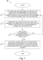
- the method comprises the steps of: receiving one or more signals from detection associated with movement of the door; based on the received signals, determining whether or not the thus detected door movement is related to an unexpected door movement; and if it is determined that detected door movement is related to an unexpected door movement, taking action so as to prevent more extensive damages.
- the step of taking action comprises activating a brake function for preventing uncontrolled movement of the door.
- the drive unit comprises at least one brake member
- the step of activating a brake function for preventing uncontrolled movement of the door comprises providing a brake force by means of the at least one brake member against the first side and/or the second side so as to prevent movement of the door.
- the drive unit further comprises a second elongated transmission member extending along the second side of the opening and the second frame section, whereby the drive unit further comprises a second driven transmission member arranged to interplay with the second elongated transmission member by means of the second elongated transmission member, the drive unit comprising a motor being in driving connection with the second driven transmission member.
- the step of receiving one or more signals from detection associated with movement of the door comprises: receiving one or more signals from detection associated with movement of the door in connection to the first side and one or more signals from detection associated with movement of the door in connection to the second side.
- the step of determining whether or not the thus detected door movement is related to an unexpected door movement comprises: comparing the signals associated with door movement in connection to the first side with the signals associated with door movement in connection the second side; and, determining that the thus detected door movement is related to an unexpected door movement if the difference of door movement in connection to the first side compared with door movement in connection the second side exceeds a certain threshold.
- damage such as a broken elongated transmission member on one side may be efficiently and accurately determined, further facilitating preventing more extensive damages by taking action.
- the drive unit comprises a first motor being in driving connection with the first driven transmission member and a second motor being in driving connection with the second driven transmission member, wherein the step of activating a brake function for preventing uncontrolled movement of the door comprises braking by means of the motor being in driving connection with the driven transmission member for which elongated transmission member and driven transmission member are still functioning.
- a brake member associated with the motor in driving connection with the driven transmission member for which elongated transmission member and driven transmission member are still functioning may be utilized.
- a first brake member may be arranged in connection to the first motor, e.g.
- second brake member may be arranged in connection to the second motor, e.g. at the motor shaft of the first motor.
- Such a brake member may be activated to provide a brake force, e.g. against that elongated transmission member and/or driven transmission member, when energy is no longer provided to that motor.
- the step of receiving one or more signals from detection associated with movement of the door comprises: receiving one or more signals from detection associated with opening and closing movement of the door during normal operation; and, storing information from the detection associated with opening and closing movement of the door during normal operation.
- the step of determining whether or not the thus detected door movement is related to an unexpected door movement comprises: comparing the signals associated with door movement with the thus stored information from the detection associated with opening and closing movement of the door during normal operation; and, determining that the thus detected door movement is related to an unexpected door movement if the difference between detected door movement compared with the thus stored information of door movement during normal operation exceeds a certain threshold.
- Normal operation herein refers to operation of the overhead door operator system involving problem free opening and closing, i.e.
- the method may comprise a step of determining whether or not detection associated with opening and closing movement refers to a normal and thus problem free opening and closing. This may be obtained by determining an average value a certain number of cycles back, which would detect sudden changes but not a gradual wear.
- unexpected door movement may be accurately determined in an easy and efficient way.
- stored information of unexpected door movement is compared with door movement, wherein it is determined that the door movement is related to unexpected door movement if the detected door movement essentially corresponds to thus stored unexpected door movement.
- unexpected door movement may be accurately determined in an easy and efficient way.
- the step of determining whether or not the thus detected door movement is related to an unexpected door movement comprises: comparing the signals associated with door movement with stored information about unexpected door movement; and, determining that the thus detected door movement is related to an unexpected door movement if the detected door movement essentially corresponds with thus stored information of unexpected door movement.
- the stored information about unexpected door movement comprises information about different types of unexpected door movements and probable cause for the respective type
- the step of determining that the thus detected door movement is related to an unexpected door movement if the detected door movement essentially corresponds with thus stored information of unexpected door movement comprises determining type of the determined unexpected door movement and thereby probable cause for the unexpected door movement.
- the method may comprise the step of filtering received false signals.
- false signals may be related to noise in electronics, small movement of the door which are not related to unexpected door movement requiring action to be taken.
- an overhead door operator system for opening and closing an opening according to claim 7.
- the overhead door operator system comprises a control device for controlling the overhead door operator system, the overhead door operator system comprising: a door frame comprising a first frame section at a first side of the opening and a second frame section at a second side of the opening opposite the first side.
- the overhead door operator system further comprises a door arranged to be moved between an open and closed position, the door being movably connected to the door frame.
- the overhead door operator system also comprises a drive unit mounted on the door, the drive unit comprising at least one motor arranged to move the door from the closed position to the open position; and a first elongated transmission member extending along the first side of the opening and the first frame section.
- the drive unit further comprises a first driven transmission member in driving connection with the motor, the first driven transmission member being movably connected to the first elongated transmission member and arranged to interplay with said first elongated transmission member for driving the first driven transmission member along said first elongated transmission member by means of the first elongated transmission member so as to move the door between the closed and open position.
- the control device is configured to: receive one or more signals from detection associated with movement of the door; based on the received signals, determine whether or not the thus detected door movement is related to an unexpected door movement; and, if it is determined that detected door movement is related to an unexpected door movement, take action so as to prevent more extensive damages.
- control device is configured to activate a brake function for preventing uncontrolled movement of the door.
- the drive unit comprises at least one brake member, wherein the control device, when activating a brake function for preventing uncontrolled movement of the door, is configured to activate the at least one brake member so as to provide a brake force by means of the at last one brake member against the first side and/or the second side so as to prevent movement of the door.
- the drive unit further comprises a second elongated transmission member extending along the second side of the opening and the second frame section, whereby the drive unit further comprises a second driven transmission member arranged to interplay with the second elongated transmission member by means of the second elongated transmission member, the drive unit comprising a motor being in driving connection with the second driven transmission member.
- the control device when receiving one or more signals from detection associated with movement of the door, is configured to: receive one or more signals from detection associated with movement of the door in connection to the first side and one or more signals from detection associated with movement of the door in connection to the second side.
- the control device when determining whether or not the thus detected door movement is related to an unexpected door movement, is configured to: compare the signals associated with door movement in connection to the first side with the signals associated with door movement in connection the second side; and, determine that the thus detected door movement is related to an unexpected door movement if the difference of door movement in connection to the first side compared with door movement in connection the second side exceeds a certain threshold.
- the drive unit comprises a first motor being in driving connection with the first driven transmission member and a second motor being in driving connection with the second driven transmission member, wherein the control device, when activating a brake function for preventing uncontrolled movement of the door is configured to activate a braking function of the motor being in driving connection with the driven transmission member for which elongated transmission member and driven transmission member are still functioning.
- the control device when receiving one or more signals from detection associated with movement of the door, is configured to: receive one or more signals from detection associated with opening and closing movement of the door during normal operation; and, store information from the detection associated with opening and closing movement of the door during normal operation.
- the control device when determining whether or not the thus detected door movement is related to an unexpected door movement, is configured to: compare the signals associated with door movement with the thus stored information from the detection associated with opening and closing movement of the door during normal operation; and, determine that the thus detected door movement is related to an unexpected door movement if the difference between detected door movement compared with the thus stored information of door movement during normal operation exceeds a certain threshold.
- Normal operation herein refers to operation of the overhead door operator system involving problem free opening and closing, i.e. raising and lowering, of the door.
- The may be configured to determine whether or not detection associated with opening and closing movement refers to a normal and thus problem free opening and closing. This may be obtained by determining an average value a certain number of cycles back, which would detect sudden changes but not a gradual wear.
- the control device when determining whether or not the thus detected door movement is related to an unexpected door movement, is configured to: compare the signals associated with door movement with stored information about unexpected door movement; and, determine that the thus detected door movement is related to an unexpected door movement if the detected door movement essentially corresponds with thus stored information of unexpected door movement.
- the stored information about unexpected door movement comprises information about different types of unexpected door movements and probable cause for the respective type, wherein the control device (100), when determining that the thus detected door movement is related to an unexpected door movement if the detected door movement essentially corresponds with thus stored information of unexpected door movement, is configured to determine type of the determined unexpected door movement and thereby probable cause for the unexpected door movement.
- control device of the overhead door operator system may be configured to filter received false signals.
- false signals may be related to noise in electronics, small movement of the door which are not related to unexpected door movement requiring action to be taken.
- the overhead door operator system according to the present disclosure has the advantages according to the corresponding method as set out herein.
- a reference to an entity being "designed for” doing something in this document is intended to mean the same as the entity being “configured for”, or “intentionally adapted for” doing this very something.
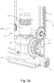
- FIG 1 is schematic views of a door operator system 1 in which the inventive aspects of the present invention may be applied.
- the door operator system comprises a door frame 3, a drive unit 10 (shown in Figure 2a-c ) and a door 8.
- the door operator system 1 is arranged to be installed in an opening 2 defined by a wall and a floor.
- the door 8 is connected to the door frame 3.
- the door operator system 1 is arranged to open and close the opening 2 by moving the door 8 between an open position O and a closed position C.
- the open position O may be a horizontal open position O, in the form of a planar horizontal position or an inclined horizontal position.
- the closed position C may be a vertical closed position C.
- the door 8 is a sectional door 8 comprising a plurality of horizontal and interconnected sections 9a-e connected to the door frame 3.
- the door is a garage door.
- the door is an industrial door. The door 8 is arranged to be moved along the door frame 3 between the closed position C and the open position O.
- the door operator system 1 may comprise a first terminal 13 and a second terminal 14.
- the at least one terminal 13, 14 is configured to transmit energy for charging an energy storage device, such as a battery, for powering the motor of the drive unit.
- an energy storage device such as a battery
- power may be supplied to motor of the drive unit by means electric wiring.
- the door operator system is an up and over door operator system.
- An up and over door operator system is a system in which the door in the closed position C is arranged substantially vertical and in the open position O is arranged substantially horizontal and inside of the opening.
- the door operator system may be a door operator system in which the door in the closed position C is arranged substantially vertical and in the open position O is arranged in an inclined position disposed between a substantially vertical and a substantially horizontal position.
- the door may be arranged at a 45 ° angle from a horizontal position in the open position O, as the skilled person recognizes however the door may be arranged at any angle disposed between the horizontal and vertical orientation of the door in the open position O.
- the door frame 3 comprises a first frame section 4 at a first side 7 of the opening 2 and a second frame section 6 at a second side 5 of the opening 2.
- the door frame 3 is connected to the wall and to the floor, i.e. the floor of the opening 2.
- the first frame section 4 comprises a substantially vertically extending part 4a and a substantially horizontally extending part 4b.
- the second frame section 6 comprises a substantially vertically extending part 6a and a substantially horizontally extending part 6b.
- the vertically extending part 4a, 6a and the horizontally extending part 4b, 6b are connected to create a path for the door 8 to glide on and a track for the drive unit 10 to interact with.
- each of the first frame section 4 and the second frame section 6 comprising a vertically extending part 4a, 6a, a horizontally extending part 4b, 6b and a bent interconnecting part 4c, 6c.
- the first frame section 4 comprises a vertically extending part 4a, a horizontally extending part 4b and a bent interconnecting part 4c.
- the bent interconnecting part 4c thus connects the vertically extending part 4a and the horizontally extending part 4b
- the second frame section 6 comprises a vertically extending part 6a, a horizontally extending part 6b and a bent interconnecting part 6c.
- the bent interconnecting part 6c thus connects the vertically extending part 6a and the horizontally extending part 6b.
- the vertically extending parts 4a, 6a may be vertical parts 4a, 6a or inclined vertical parts 4a, 6a.
- the horizontally extending parts 4b, 6b may horizontal parts 4b, 6b or inclined horizontal parts 4b, 6b.
- the door 8 is directly or indirectly connected to the door frame 3.
- the door 8 is at a first side moveably connected to the first frame section 4 and at a second side moveably connected to the second frame section 6.
- one or more of the plurality of sections 9a-e is connected to the first frame section 4 at said first side 7 and to the second frame section 6 at said second side 5.
- the drive unit 10 is mounted on the door 8.
- the drive unit 10 comprises at least one motor 11.
- the at least one motor 11 is arranged to move the door 8 from the closed position C to the open position O.
- the drive unit comprises a motor on both sides of the door.
- the overhead door operator system 1 further comprises an elongated transmission member 19 extending along the first side 7 of the opening 2.
- the elongated transmission member 19 may further extend along the first frame section 4.
- the drive unit 10 further comprises a driven transmission member 18 which is in driving connection with the motor 11.
- the driven transmission member 18 is movably connected to the elongated transmission member 19 and arranged to interplay with said elongated transmission member 19 for driving the driven transmission member 18 along said elongated transmission member 19 by means of the elongated transmission member 19 at least partially wrapping around the driven transmission member 18.
- the elongated transmission member 19 is arranged to at least partially envelope said driven transmission member 18.
- the elongated transmission member does in comparison with a fixed rack provide a more cost-efficient solution both in terms of manufacturing and installation. Furthermore, the elongated transmission member allows for relative movement between the door 8 and the frame and does not require a high accuracy and proper aligning in the same manner as a fixed rack solution.
- the elongated transmission member may thus be arranged to allow for a degree of movement along a direction orthogonal to the first frame section 4.
- the elongated transmission member enables a safer door operator system due to said elongated transmission member following and keeping the engagement with the driven transmission member, at least to some extent, even if the door is pushed away from the rail.
- the elongated transmission member is more silent and resistant to wear compared to a fix rack and less likely to malfunction due to pinching of external objects.
- the elongated transmission member 19 may be in the form of a bendable transmission member.
- the elongated transmission member 19 may be in the form of a suspended transmission member. It is noted that bendable in this context does not necessarily imply that said transmission member necessarily is flexible but only that it allows for wrapping around the driven transmission member. Accordingly, the transmission member 19 may be considered to be arranged to be in engagement with the driven transmission member 18 and provide for relative movement between the driven transmission member 18 and a direction of movement of the door 8 as defined by the frame 3. Worded differently said transmission member may be considered as a non-fix transmission member or a suspended transmission member. The elongated transmission member may accordingly be arranged to engage the driven transmission member independently of the frame.
- the drive unit 10 is moveably connected to the elongated transmission member 19. Accordingly, drive unit 10 is connected to said elongated transmission member 19 so as to allow for relative movement between the door and the frame, whereby the drive unit is fixed to the door.
- the drive unit 10 comprises at least one motor 11.
- the drive unit 10 is arranged to move the door 8 from the closed position to the open position.
- the at least one motor 11 may be connected to at least one energy storage device, such as a battery, arranged to power the at least one motor 11.
- the drive unit 10 is arranged to move the door 8 from the closed position C to the open position O.
- the drive unit 10 is arranged to move the door from the open position O to the closed position C.
- the door 8 is arranged to move from the open position O to the closed position C by means of the weight of the door 8.
- the drive unit 10 is arranged to brake the door 8 when moving from the open position O to the closed position C.
- the elongated transmission member may be suspended only by means of a top end and a bottom end.
- the elongated transmission member 19 may be biased.
- the biasing of the elongated transmission member 19 enables keeping of the tension of the resilient elongated member 19 at a suitable level and further compensates for wear and potential tolerance issues.
- the elongated transmission member 19 may be biased by means of a spring arrangement.
- a top end of the elongated transmission member 19 may be fixedly mounted and a bottom end of said elongated transmission member 19 may be spring-loaded. This allows for easier access for an operator performing service work involving the spring.
- the top and bottom end of the elongated transmission member 19 is mounted to the frame, for example the first frame section 4.
- the overhead door operator system further comprises at least one guide member 92.
- the at least one guide member 92 is mounted to the door 8.
- the guide member 92 may be arranged to interplay with the elongated transmission member 19 for guiding the door 8 along the elongated transmission member 19 by means of the elongated transmission member 19 at least partially wrapping around the at least one guide member 92.
- the guide member 92 thus moves the elongated transmission member 19 and guides the driven transmission member 18 in relation to said elongated transmission member 19 to properly align them.
- the guide member 92 may preferably be a rotatable guide member which may be mounted to the door 8 by means of a journaled connection.
- the elongated transmission member 19 may be arranged to at least partially envelope said guide member 92.
- the elongated transmission member 19 may be arranged to wrap around and interplay with a portion of the driven transmission member 18 and a portion of the guide member 92.
- the portion of the driven transmission member 18 interplaying with the elongated transmission member 19 being opposite to the portion of the guide member 92 interplaying with said elongated transmission member 19.
- the elongated transmission member 19 is there suspended along the first side 7 of the opening.
- the elongated transmission member 19 may be any conventional elongated transmission member 19 providing the required slack to compensate for horizontal or diagonal movement of the drive unit and/or door.
- the elongated transmission member may be a belt or a chain.
- the elongated transmission member 19 may be a belt.
- the guide member 92 and the driven transmission member 18 may be pulley elements arranged to interface with said belt.
- the belt may be a cogged belt or a ribbed belt, whereby the guide member 92 and the driven transmission member 18 may be cogged wheels interfacing with the ribs of said cogged or ribbed belt.
- the elongated transmission member 19 may also be a chain, which is depicted in Figure 2a-c .
- the chain may be provided with slots for receiving cogs.
- the driven transmission member 18 may be a cogged wheel arranged to interplay with the chain, e.g. the slots of the chain.
- the driven transmission member 18 may be a sprocket.
- the guide member 92 may be a cogged wheel arranged to interplay with the chain, e.g. the slots of the chain.
- the guide member 92 may be a sprocket.
- the guide member 92 may be a ribbed wheel for interplaying with the chain.
- the chain is an endless chain enveloping the guide member(s) and the driven transmission member(s). In one embodiment, the chain is a non-endless chain, e.g. a single chain only partially enveloping the guide member(s) and the driven transmission member(s).
- the overhead door operator system further comprises a first set of guide rollers 17 and a second set of guide rollers 17. Said first and second set of guide rollers are mounted to the door 8.
- the first set of guide rollers 17 are arranged to interplay with the first frame section 4 and the second set of guide rollers 17 are arranged to interplay with the second frame section 6.
- the guide rollers thus moves together with the door 8 in a guided manner along the trajectory formed by the frame, e.g. the first frame section 4 and the second frame section 6.
- the door 8 is a sectional door.
- the door comprises a plurality of horizontal and interconnected sections 9a-e (as depicted in Figure 1 ).
- the drive unit 10 is mounted on a section 9e of the door 8.
- the section onto which the drive unit 10 is mounted is provided with two pairs of guide rollers.
- a first and second upper guide roller accordingly extend from the section 9e towards the first frame section 4 and the second frame section 6, respectively.
- a first and second lower guide roller extend from the section 9e towards the first frame section and the second frame section 6, respectively.
- the drive unit 10 is mounted to the bottommost section 9e of the door 8.
- the first and second lower guide roller may be disposed adjacent to a bottom horizontal end phase of the bottommost section 9e.
- the upper guide rollers may correspondingly be disposed adj acent to a top horizontal end phase of the bottommost section 9e.
- upper and lower guide rollers may be mounted to each section 9a-e.
- the upper guide rollers are disposed adjacent to the upper horizontal end phase and the lower guide rollers are disposed adjacent to the bottom horizontal end phase of each section.
- the at least one guide member 92 may be arranged coaxially with one of the guide rollers 17.
- the coaxial arrangement reduces the force on the guide member due to the frame and guide roller taking up some of the load during the movement of the door. Hence, resulting forces to the door sections and bearings of the drive unit and/or guide member are reduced. Furthermore the coaxial arrangement allows for more of the elongated transmission member to be disposed behind the guide rollers which decreases the exposure of said elongated transmission member.
- the guide roller 17 is mounted to the door 8 by means of a shaft 88. Both the guide roller 17 and the guide member 92 are mounted to the shaft.
- the guide member 92 may be fixedly attached to the shaft 88.
- the guide roller 17 and the guide member 92 may be arranged adjacent to the bottom horizontal edge of the door 8. In one embodiment, the guide member is integrated into the guide roller.
- Coaxial herein implies that the guide roller and the guide member are arranged parallel to each other along a horizontal axis extending.
- the horizontal axis extends between the first and second frame section.
- the guide member is coaxial with the guide roller being disposed adjacent to a bottom horizontal end phase of the bottommost section 9e of the door. This is particularly advantageous due to it providing a superior pivoting position of the door.
- the guide roller and the guide element hence creates a common low pivot point for the door when the door is approaching its open position O when the overhead door operator system is an up and over door operator system. This significantly reduces the space required above the door opening compared to for example a door with driven sections utilising for example a fix rack.
- a first upper guide member 92 is arranged coaxially with the first upper guide roller 17.
- a first lower guide member 92 is arranged coaxially with the first lower guide roller 17.
- the section 9e which is driven may be both guided along the elongated transmission member 17 and the frame at the same axes. This further increases the stability and decreases the load on the section onto which the drive unit 10 is mounted.
- the section is the bottommost section and the lower guide member and the lower guide wheel are arranged adjacent to the bottom phase of said bottommost section.
- one of the guide rollers 17 and one of the guide member 92 may be arranged coaxially to each other adjacent to the bottom horizontal edge of the door 8. This may be the case in a single section door as well.
- the overhead door operator system comprise a pair of elongated transmission members to allow for a more stable movement pattern of the door 8.
- a first elongated transmission member 19 extends along the first side 7 of the opening 2.
- the first elongated transmission member 19 may further extend along the first frame section 4.
- a second elongated transmission member 19 extends along the second side 5 of the opening 2.
- the second elongated transmission member 19 may further extend along the second frame section 6.
- the overhead door operator system comprises a first and second driven transmission member 18 arranged to interplay with the first and second elongated member 19 by means of the first and second elongated transmission member at least partially wrapping around the first and second driven transmission member, respectively.
- the first and second driven transmission member 18 may be driven by means of a single or multiple motors 11.
- a single motor 11 is in driving connection with the first and second transmission member 18.
- the single motor 11 may be connected to the first and second driven transmission members 18 by means of a first and second shaft extending from the motor 11.
- the drive unit 10 according to the invention comprises a first and a second motor each being in driving connection with the first and second driven transmission member 18, respectively.
- the second side of the door may have one or more guide members mounted thereon.
- the overhead door operator system further comprises at least one guide member 92 mounted to the door 8 arranged to interplay with the second elongated transmission member for guiding the door 8 along the second elongated transmission member 17 by means of the second elongated transmission member at least partially wrapping around said guide member.
- said door operator system comprises at least one first guide member 92 mounted on the door 8 arranged to interplay with the first elongated transmission member 19 and at least one second guide member 92 mounted on the door 8 arranged to interplay with the second elongated transmission member 19 by means of the first and second elongated transmission member at least partially wrapping around the first and second guide member, respectively.
- Both the elongated transmission members 19 may be biased by means of spring arrangements.
- a top end of the elongated transmission members 19 may be fixedly mounted and a bottom end of said elongated transmission members 19 may be spring-loaded. This allows for easier access for an operator performing service work involving the spring.
- the top and bottom ends of the elongated transmission members 19 are mounted to the frame, .e.g. to the first and second frame section, respectively.
- the first driven transmission member 18 may be arranged between a first upper and a lower guide member 92.
- the first upper and lower guide member 92 are arranged to interplay with the first elongated transmission member 19 by means of the first elongated transmission member at least partially wrapping around the first upper and lower guide member.
- the second driven transmission member 18 may be arranged between a second upper and a lower guide member 92.
- the second upper and lower guide member 92 are arranged to interplay with the second elongated transmission member by means of the second elongated transmission member at least partially wrapping around the second upper and lower guide member.
- the first and second driven transmission member 18 may thus be arranged to extend from the door 8 in opposite directions towards the first and second elongated transmission member 19, respectively.
- the first driven transmission member 18 may be arranged proximal to a first vertical phase of the door, said first phase being adjacent to the first elongated transmission member when the door is in the closed position.
- the second driven transmission member 18 may be arranged proximal to a second vertical phase of the door, said second phase being adj acent to the second elongated transmission member when the door is in the closed position.
- the elongated transmission members 19 may be arranged to wrap around and interplay with a portion of the driven transmission member 18 and a portion of the upper and lower guide members 92.
- the portion of the driven transmission member 18 interplaying with the elongated transmission member 19 being opposite to the portions of the upper and lower guide member 92 interplaying with said elongated transmission member 19. This achieves a larger interface between the driven transmission member, guide member and elongated transmission member, whereby a more stable overhead door operator system which requires less torque to operate may be achieved.
- the door operator system may only comprise a first upper and lower guide member according to the above.
- a first upper guide member 92 arranged to interplay with the first elongated transmission member 19 may be arranged adjacent to a top phase of the section 9e.
- a first lower guide member 92 arranged to interplay with the first elongated transmission member 19 may be arranged adjacent to a bottom phase of the section 9e.
- a second upper guide member 92 arranged to interplay with the second elongated transmission member 19 may be arranged adjacent to a top phase of the section 9e.
- a second lower guide member 92 arranged to interplay with the second elongated transmission member 19 may be arranged adjacent to a bottom phase of the section 9e.
- the first upper guide member 92 may be arranged coaxially with the first upper guide roller 17 for interplaying with the first elongated transmission member 19 by means of the first elongated transmission member at least partially wrapping around the first upper and lower guide member.
- the first lower guide member 92 may be arranged coaxially with the first lower guide roller 17 for interplaying with the first elongated transmission member 19.
- the second upper guide member 92 may be arranged coaxially with the second upper guide roller 17 for interplaying with the second elongated transmission member 19 by means of the second elongated transmission member at least partially wrapping around the second upper and lower guide member.
- the second lower guide member 92 may be arranged coaxially with the second lower guide roller 17 for interplaying with the second elongated transmission member 19.
- the drive unit 10 may comprise a reduction gearing 76 to provide additional torque between the motor and the driven transmission member 18.
- the reduction gearing 76 connects the driven transmission member 18 and the motor 11.
- the reduction gearing may be in the form of a gearbox 76.
- a gearbox 76 enables selective torque control between for example a high speed mode and a high torque mode of the door operator system.
- the drive unit 10 comprises a single motor
- the motor is connected to the reduction gearing 76 which may be in the form of the gearbox, whereby an output shaft of the gearbox is connected to the first and second driven transmission member 18 so as to transfer torque to said first and second driven transmission member 18, or in the case of the operator system only having one elongated transmission member, the single driven transmission member.
- the drive unit 10 comprises the first and second motor.
- the first motor may be connected to a first reduction gearing, such as a gearbox, in turn connected to the first driven transmission member.
- the second motor may be connected to a second reduction gearing, such as a gearbox, in turn connected to the second driven transmission member.
- the transmission member protector 61 may be arranged to extend outwardly, i.e. horizontally, from the door 8 across the elongated transmission member 19 to cover said elongated transmission member 19.
- the transmission member protector 61 may be attached to the door 8 or the drive unit 10.
- the overhead door operator system may comprise a plurality of transmission member protectors 61.
- Each transmission member protector 61 may be arranged to at least partially enclose a corresponding driven transmission member 18 and the portion of the elongated transmission member 19 interplaying with said driven transmission member 18.
- the overhead door operator system may further comprise a transmission member tensioner for spring-loading the elongated transmission member 19, wherein the top and bottom end of the elongated transmission member 19 are fixedly mounted and the transmission member tensioner is attached to the door 8.
- the transmission member tensioner may comprise a roller element arranged to interplay with the elongated transmission member 19.
- the overhead door operator system may comprise a spring arrangement.
- the bottom end of the elongated transmission member 19 may be attached to a fix point by means of said spring arrangement.
- the fix point may be a point on the frame or the floor.
- the spring arrangement may be connected to the frame 3, for example the first frame section 4, and the bottom end of the elongated transmission member 19.
- the elongated transmission member 19 may be routed downwards around a console element disposed adjacent to the floor of the opening and upwards towards the spring arrangement.
- the overhead door operator system may further comprise a resilient panel 91.
- the resilient panel 91 is attached to the door 8.
- the resilient panel 91 extends from the bottom horizontal edge 8 of the door and is further arranged to come into contact with a floor of the opening 2 when the door is in the closed position C.
- Said resilient panel 91 deforms when coming into contact with the floor upon the door 8 closing, whereby the door 8 is protected from the impact and wear due to coming into direct contact with the floor.
- the resilient panel 91 may provide a sealing effect between the floor and the door when the door is in the closed position.
- the resilient panel 91 may be in a rubber material.
- FIG. 3a-b which more closely depicts an overhead door operator system in which the drive unit comprises two motors 11a, 11b.
- the first motor 11a and second motor 11b may be arranged on the same horizontal section 9e of the door 8.
- the first and second motor may be arranged on the bottommost horizontal section 9e of the door 8.
- the first motor 11a and the second motor 1 1b may be mounted at different vertical sides of the door 8, e.g. the first motor 11a may be disposed at a vertical side of the door 8 proximal to the first side 7 of the opening and the second motor 1 1b may be disposed at a vertical side of the door 8 proximal to the second side 5 of the opening.
- the drive unit 10 at least comprises a first motor 11a and a second motor 11b, the first motor 11a and the second motor 11b may be mounted at the same vertical sides of the door 8.
- the first and second motor may be arranged on the same horizontal section of the door 8.
- the first and second motor may be arranged on the bottommost horizontal section 9e of the door 8.
- the motors 11 and the drive unit 10 are preferably arranged on the same main phase of the door 8, e.g. an outer or inner phase of the door 8. To protect the motors 11 and drive unit 10, said motors and drive unit are arranged on an inner phase of the door in the form of an interior facing door phase of the door 8.
- the control device 100 is configured to activate a brake function for preventing uncontrolled movement of the door.
- the drive unit 10 may comprise at least one brake member 30a, 30b.
- the control device 100 when activating a brake function for preventing uncontrolled movement of the door, may be configured to activate the at least one brake member so as to provide a brake force by means of the at last one brake member against the first side 7 and/or the second side 5 so as to prevent movement of the door.
- the control device 100 when taking action, may be configured to prevent operation of the door operator system 1 associated with opening and closing the opening 2.
- the first and second motor 11a, 11b are arranged on a section 9e that is located on the section 9 of the door being closest to the floor in the closed position C.
- the section 9e could for example also be the section 9d which is the section being arranged next to the section being closest to the floor in the closed position C.
- first, second, third or the first, second, third and fourth motor may be arranged on a section 9.
- said motors may be arranged on the bottommost section 9e.
- At least one motor 11 of the drive unit 10 is configured to brake the movement of the door 8 when the door 8 is moved from the open position O to the closed position C.
- both the first and second motor 11a and 1 1b are configured to brake the movement of the door 8 when the door 8 is moved from the open position O to the closed position C.
- the brake function of the first motor 11a and/or second motor 11b may be activated if it has been determined that detected movement of the door 8 is related to an unexpected door movement.
- At least one of the first and second motor 11 is run as a generator 11 when moving the door 8 from the open position O to the closed position C.
- the generator 11 As the sprocket(s) 18 are rotated the generator 11 is rotated.
- the generator 11 reduces the speed of the door 8.
- the generator 11 that is connected to the energy storage device charges said energy storage device when moved. By using the kinetic energy of the moving door 8 the energy storage device is charged.
- the overhead door operator system may comprise a transmission mounting arrangement, not shown.
- the transmission mounting arrangement is for attaching the elongated transmission member 19.
- link may refer to a communication link which may be a physical connector, such as an optoelectronic communication wire, or a non-physical connector such as a wireless connection, for example a radio or microwave link.
- the overhead door operator system comprises a control device 100 for controlling the overhead door operator system.
- the overhead door operator system comprises a door frame comprising a first frame section at a first side of the opening and a second frame section at a second side of the opening opposite the first side.
- the overhead door operator system further comprises a door arranged to be moved between an open and closed position, the door being movably connected to the door frame.
- the overhead door operator system further comprises; a drive unit mounted on the door, the drive unit comprising at least one motor arranged to move the door from the closed position to the open position; and a first elongated transmission member extending along the first side of the opening and the first frame section, whereby the drive unit further comprises a first driven transmission member in driving connection with the motor.
- the first driven transmission member is movably connected to the first elongated transmission member and arranged to interplay with said first elongated transmission member for driving the first driven transmission member along said first elongated transmission member by means of the first elongated transmission member so as to move the door between the closed and open position.
- the drive unit further comprises a second elongated transmission member extending along the second side of the opening and the second frame section whereby the drive unit further comprises a second driven transmission member arranged to interplay with the second elongated transmission member by means of the second elongated transmission member.
- the drive unit comprises a motor being in driving connection with the second driven transmission member.
- the drive unit of the overhead door operator system may according to an aspect of the present disclosure have a motor which is in driving connection with both the first driven transmission member and the second driven transmission member.
- the drive unit of the overhead door operator system may according to another aspect of the present disclosure comprise a first motor being in driving connection with the first driven transmission member and a second motor being in driving connection with the second driven transmission member.
- the control device 100 may comprise one or more control units.
- the control device 100 may comprise two or more separate control units, but operably connected to each other.
- the control device 100 may be comprised in or operably connected to the drive unit of the overhead door operator system.
- the control device 100 is configured to receive one or more signals from detection associated with movement of the door.
- the control device 100 is configured to receive one or more signals from a detection device 110 for detecting movement of the door of the overhead door operator system I.
- the overhead door operator system I may comprise or be operably connectable to the detection device 110.
- the detection device 110 for detecting movement of the door of the overhead door operator system I may be arranged in connection to the door so as to detect door movement.
- the control device 100 may be operably connected to the detection device 110 via a link L 10.
- the control device 100 may, via said link L 10, be arranged to receive one or more signals from detection associated with movement of the door.
- control device 100 may, when receiving one or more signals from detection associated with movement of the door, be configured to receive acceleration signals and/or vibration signals from detection of movement of the door by means of one or more acceleration sensors arranged in connection to the door.
- the detection device 110 comprises one or more acceleration detection units 112.
- the acceleration detection units may comprise one or more accelerometers.
- the overhead door operator system I may comprise or be operably connectable to the one or more acceleration detection units 112.
- the one or more acceleration detection units 112 may be arranged in connection to the door so as to detect door movement.
- the one or more acceleration detection units 112 may comprise one or more acceleration detection units arranged at the door in connection to the first side so as to detect door movement in connection to that side, and one or more acceleration detection units arranged at the door in connection to the opposite second side so as to detect door movement in connection to that side.
- the detection device 110 comprises one or more vibration detection units.
- the control device 100 may be operably connected to the one or more acceleration detection units 112 via one or more links L12.
- the control device 100 may, via said one or more links L12, be arranged to receive one or more acceleration signals and/or vibration signals from detection of movement of the door.
- control device 100 may, when receiving one or more signals from detection associated with movement of the door, be configured to receive torque signals from detection of torque of the at least one motor of the door by means of torque sensor arranged in connection to the at least one motor.
- the detection device 110 comprises one or more torque detection units 114 for detecting torque of the at least one motor of the drive unit.
- the overhead door operator system I may comprise or be operably connectable to the one or more torque detection units 114.
- the one or more torque detection units 114 may comprise one or more torque detection units arranged at the first motor so as to detect torque of the first motor arranged in connection to the first side, and one or more torque detection units arranged at the second motor so as to detect torque of the second motor arranged in connection to the opposite second side.
- the control device 100 may be operably connected to the one or more torque detection units 114 via one or more links L14.
- the control device 100 may, via said one or more links L14, be arranged to receive one or more torque signals from detection of torque of the at least one motor of the drive unit.
- the detection device 110 may comprise one or more acceleration detection units 112 and/or vibration detection units and/or one or more torque detection units 114.
- the control device 100 is configured to determine whether or not the thus detected door movement is related to an unexpected door movement based on the thus received one or more signals from detection associated with movement of the door.
- the overhead door operator system I may comprise or be operably connectable to a door movement characteristics determination device 120 for determining if detected door movement is related to an unexpected door movement.
- the control device 100 may comprise and/or be operably connectable to the door movement characteristics determination device 120.
- the control device 100 may be operably connected to the door movement characteristics determination device 120 via a link L20a.
- the control device 100 may, via said link L20a, be arranged to send one or more signals from detection associated with door movement.
- the control device 100 may be operably connected to the door movement characteristics determination device 120 via a link L20b.
- the control device 100 may, via said link L20b, be arranged to receive one or more signals from the door movement characteristics determination device 120 representing data for unexpected door movement.
- the control device 100 is configured to determine whether or not the thus detected door movement is related to an unexpected door movement based on the thus received signals from detection associated with movement of the door in connection to the first side and the one or more signals from detection associated with movement of the door in connection to the second side.
- the control device 100 is configured to compare the signals associated with door movement in connection to the first side with the signals associated with door movement in connection the second side, and determine that the thus detected door movement is related to an unexpected door movement if the difference of door movement in connection to the first side compared with door movement in connection the second side exceeds a certain threshold.
- the door movement characteristics determination device 120 comprises a side door movement comparison device 122 for comparing the signals associated with door movement in connection to the first side with the signals associated with door movement in connection the second side.
- the side door movement comparison device 122 may be comprised in or operably connected to the control device 100.
- the control device 100 may be operably connected to the side door movement comparison device 122 via a link L22a.
- the control device 100 may, via said link L22a, be arranged to send one or more signals from detection associated with door movement at the first side.
- the control device 100 may be operably connected to the side door movement comparison device 122 via a link L22b.
- the control device 100 may, via said link L22b, be arranged to send one or more signals from detection associated with door movement at the second side.
- the control device 100 may be operably connected to the side door movement comparison device 122 via a link L22c.
- the control device 100 may, via said link L22c, be arranged to receive one or more signals from the side door movement comparison device 122 representing data for unexpected door movement.
- the control device 100 is configured to store information from the detection associated with opening and closing movement of the door during normal operation. According to an aspect of the present disclosure, the control device 100 may also be configured to store information from detection associated with door movement on the respective side. According to an aspect of the present disclosure, the control device 100 may also be configured to store information from detection associated with unexpected door movement. According to an aspect of the present disclosure, the control device 100 may, when storing information from detection associated with unexpected door movement, be configured to store type of unexpected door movement, i.e. the cause of the unexpected door movement. The cause of an unexpected door movement may e.g. be a broken transmission member, e.g. chain, or a direct impact on the door by a vehicle or the like.
- the door movement characteristics determination device 120 comprises a storage device 124a.
- the storage device 124a is according to an aspect configured for storing signals associated with opening and closing movement of the door during normal operation.
- the storage device 124a may according to an aspect further be configured for storing signals associated with unexpected door movement.
- the storage device 124a may be comprised in or operably connected to the control device 100.
- the control device 100 may be operably connected to the storage device 124a via a link L24a1.
- the control device 100 may, via said link L24a1, be arranged to send signals associated with opening and closing movement of the door during normal operation, which are stored in the storage device 124a.
- the control device 100 may be operably connected to the storage device 124a via a link L24a2.
- the control device 100 may, via said link L24a2, be arranged to send signals associated with unexpected door movement, which are stored in the storage device 124a.
- control device 100 is configured to determine whether or not the thus detected door movement is related to an unexpected door movement based on the thus stored information from the detection associated with opening and closing movement of the door during normal operation. According to an aspect of the present disclosure, the control device 100 is configured to compare the signals associated with door movement with the thus stored information from the detection associated with opening and closing movement of the door during normal operation, and that the thus detected door movement is related to an unexpected door movement if the difference between detected door movement compared with the thus stored information of door movement during normal operation exceeds a certain threshold.
- control device 100 may be configured to compare the signals associated with door movement with the thus stored information from the detection associated with unexpected door movement, and determine that the thus detected door movement is related to an unexpected door movement if the detected door movement essentially coincides with the thus stored information of unexpected door movement.
- the door movement characteristics determination device 120 comprises a stored door movement comparison device 124b for comparing the signals associated with door movement with the thus stored information.
- the stored door movement comparison device 124b may be configured to compare the signals associated with door movement with the thus stored information from the detection associated with opening and closing movement of the door during normal operation.
- the stored door movement comparison device 124b may be configured to compare the signals associated with door movement with the stored information about unexpected door movement.
- the stored door movement comparison device 124b may be comprised in or operably connected to the control device 100.
- the storage device 124a may be operably connected to the stored door movement comparison device 124b via a link L24-1.
- the stored door movement comparison device 124b may, via said link L24a1, be arranged to receive signals associated with data of stored opening and closing movement of the door during normal operation.
- the control device 100 may be operably connected to the stored door movement comparison device 124b via a link L24b1.
- the control device 100 may, via said link L24b1, be arranged to send signals from detection associated with movement of the door.
- the control device 100 may be operably connected to stored door movement comparison device 124b via a link L24a2.
- the control device 100 may, via said link L24a2, be arranged to receive signals based on comparison as a basis for determining whether or not the thus detected door movement is related to an unexpected door movement.
- control device 100 is configured to take action so as to prevent more extensive damages.
- the overhead door operator system I may comprise or be operably connectable to a damage prevention device 130 for taking action so as to prevent more extensive damages in connection to detection of unexpected door movement.
- the control device 100 may comprise and/or be operably connectable to the damage prevention device 130.
- the damage prevention device 130 may be comprised in the drive unit.
- the control device 100 may be operably connected to the damage prevention device 130 via a link L30.
- the control device 100 may, via said link L30, be arranged to send signals to the damage prevention device 130 so as to activate the damage prevention device for preventing more extensive damages due to a determined unexpected door movement.
- the control device 100 is configured to activate a brake function for preventing uncontrolled movement of the door.
- the damage prevention device 130 may comprise at least one brake member 132.
- the control device when activating a brake function for preventing uncontrolled movement of the door, is configured to activate the at least one brake member 132 so as to provide a brake force by means of the at last one brake member against the first side and/or the second side so as to prevent movement of the door.
- the at least one brake member 132 may be comprised in the drive unit.
- the at least one brake member 132 is arranged in connection to the at least one motor of the drive unit and configured to activate in connection to deactivation of the motor.
- the damage prevention device 130 may comprise a first brake member 132 arranged in connection to the first motor and a second brake member 132 arranged in connection to the second motor.
- the first brake member will be activated by providing a brake force against the first driven transmission member if an unexpected door movement associated with a damaged/broken second driven transmission member is determined, and vice versa.
- the at least one brake member 132 may be arranged in connection to the door and be configured to provide a brake force against the first frame section and/or the second frame section of the door frame.
- the control device 100 may be operably connected to the at least one brake member 132 via one or more links L32.
- the control device 100 may, via said one or more links L32, be arranged to send signals to the at least one brake member 132 so as to activate the at least one brake member 132 for activating a brake function for preventing uncontrolled movement of the door.
- the control device 100 is configured to prevent operation of the door operator system associated with opening and closing the opening.
- the damage prevention device 130 may comprise an operation prevention device 134 for preventing operation of the door operator system associated with opening and closing the opening.
- the control device 100 may comprise and/or be operably connectable to the operation prevention device 134.
- the operation prevention device 134 may be comprised in the drive unit.
- the control device 100 may be operably connected to the operation prevention device 134 via a link L34.
- the control device 100 may, via said link L34, be arranged to send signals to the operation prevention device 134 so as to activate the prevention device 134 for preventing operation of the door operator system associated with opening and closing the opening.
- the control device 100 is according to an embodiment, adapted to perform the method M1 described below with reference to fig. 9 .
- the control device 100 is according to an embodiment, adapted to perform the method M2 described below with reference to fig. 10.
- the control device 100 is according to an embodiment, adapted to perform the method M3 described below with reference to fig. 11.
- the control device 100 is according to an embodiment, adapted to perform the method M4 described below with reference to fig. 12.
- Figure 5-9 show schematic flowcharts of a method M1; M2, M3; M4 and M5, for controlling an overhead door operator system for opening and closing an opening according to an aspect of the present disclosure.
- the methods may be performed by means of a control device, e.g. a control device 100 as described with reference to fig. 4 .
- the methods may be combined in any suitable manner.
- the overhead door operator system comprises: a door frame comprising a first frame section at a first side of the opening and a second frame section at a second side of the opening opposite the first side.
- the overhead door operator system further comprises a door arranged to be moved between an open and closed position, the door being movably connected to the door frame.
- the overhead door operator system further comprises; a drive unit mounted on the door, the drive unit comprising at least one motor arranged to move the door from the closed position to the open position; and a first elongated transmission member extending along the first side of the opening and the first frame section, whereby the drive unit further comprises a first driven transmission member in driving connection with the motor.
- the first driven transmission member is movably connected to the first elongated transmission member and arranged to interplay with said first elongated transmission member for driving the first driven transmission member along said first elongated transmission member by means of the first elongated transmission member so as to move the door between the closed and open position.
- Figure 5 shows a schematic flowchart of a method M1 for controlling an overhead door operator system for opening and closing an opening according to an aspect of the present disclosure.
- the method M1 comprises a step S1.
- this step one or more signals are received from detection associated with movement of the door.
- the method M1 comprises a step S3. In this step, if it is determined that detected door movement is related to an unexpected door movement, action is taken so as to prevent more extensive damages.
- Figure 6 shows a schematic flowchart of a method M2 for controlling an overhead door operator system for opening and closing an opening not covered by the claims.
- the method M2 comprises a step S11.
- one or more acceleration signals and/or vibration signals are received from detection associated with movement of the door, and/or one or more torque signals are received from detection of torque of the at least one motor of the door.
- Acceleration movement of the door may be detected by means of any suitable acceleration detection unit arranged in connection to the door.
- the acceleration detection unit may comprise one or more accelerometers.
- Torque of the at least one motor may be detected by means of one or more torque detection units.
- the one or more torque detection units may comprise one or more torque detection units arranged at each of the at least one motor.
- Unexpected door movement may be associated with a damaged/broken elongated transmission member and/or damaged/broken driven transmission member. Unexpected door movement may be associated with a direct impact on the door, e.g. by a vehicle or the like.
- the method M2 comprises a step S13.
- a brake function for preventing uncontrolled movement of the door is activated and/or operation of the overhead door operator system associated with opening and closing the opening is prevented.
- Figure 7 shows a schematic flowchart of a method M3 for controlling an overhead door operator system for opening and closing an opening according to the invention.
- the drive unit further comprises a second elongated transmission member extending along the second side of the opening and the second frame section whereby the drive unit further comprises a second driven transmission member arranged to interplay with the second elongated transmission member by means of the second elongated transmission member.
- the drive unit comprises a motor being in driving connection with the second driven transmission member.
- the drive unit of the overhead door operator system may according to an aspect of the present disclosure have a motor which is in driving connection with both the first driven transmission member and the second driven transmission member.
- the drive unit of the overhead door operator system may according to another aspect of the present disclosure comprise a first motor being in driving connection with the first driven transmission member and a second motor being in driving connection with the second driven transmission member, wherein the step of receiving one or more signals from detection associated with movement of the door comprises.
- the method M3 comprises a step S21.
- this step one or more signals are received from detection associated with movement of the door in connection to the first side and one or more signals are received from detection associated with movement of the door in connection to the second side.
- the method M3 comprises a step S22.
- the signals associated with door movement in connection to the first side are compared with the signals associated with door movement in connection the second side.
- the method M3 comprises a step S22. In this step it is determined that the thus detected door movement is related to an unexpected door movement if the difference of door movement in connection to the first side compared with door movement in connection the second side exceeds a certain threshold.
- Unexpected door movement may be associated with a damaged/broken elongated transmission member and/or damaged/broken driven transmission member.
- the method M3 comprises a step S24.
- a brake function for preventing uncontrolled movement of the door is activated and/or operation of the overhead door operator system associated with opening and closing the opening is prevented.
- Figure 8 shows a schematic flowchart of a method M4 for controlling an overhead door operator system for opening and closing an opening according to an aspect of the present disclosure.
- the method M4 comprises a step S31A.
- this step one or more signals are received from detection associated with opening and closing movement of the door during normal operation.
- the method M4 comprises a step S31B.
- this step information from the detection associated with opening and closing movement of the door during normal operation is stored.
- the method M4 comprises a step S31.
- this step one or more signals are received from detection associated with movement of the door.
- the method M4 comprises a step S32.
- the signals associated with door movement are compared with the thus stored information from the detection associated with opening and closing movement of the door during normal operation.
- the method M4 comprises a step S33. In this step it is determined that the thus detected door movement is related to an unexpected door movement if the difference between detected door movement compared with the thus stored information of door movement during normal operation exceeds a certain threshold.
- Unexpected door movement may be associated with a damaged/broken elongated transmission member and/or damaged/broken driven transmission member. Unexpected door movement may be associated with a direct impact on the door, e.g. by a vehicle or the like.
- the method M4 comprises a step S34.
- a brake function for preventing uncontrolled movement of the door is activated and/or operation of the overhead door operator system associated with opening and closing the opening is prevented.
- the method M4 may comprise a step in which one or more signals are received from detection associated with unexpected movement of the door, and a step in which information from the detection associated with unexpected movement of the door is stored.
- the signals associated with door movement are compared with the thus stored information from the detection associated with unexpected movement.
- it is then determined that the thus detected door movement is related to an unexpected door movement if the detected door movement essentially corresponds with the thus stored information of unexpected door movement.
- Figure 9 shows a schematic flowchart of a method M5 for controlling an overhead door operator system for opening and closing an opening according to an aspect of the present disclosure.
- the method M5 comprises a step S41.
- this step one or more signals are received from detection associated with movement of the door.
- the method M5 comprises a step S42.
- the signals associated with door movement are compared with stored information about unexpected door movement.
- the stored information about unexpected door movement may comprise information about different types of unexpected door movements and probable cause for the respective type.
- the method M5 comprises a step S43.
- this step it is determined that the thus detected door movement is related to an unexpected door movement if the detected door movement essentially correspond with stored information of unexpected door movement.
- the step of determining that the thus detected door movement is related to an unexpected door movement if the detected door movement essentially corresponds with thus stored information of unexpected door movement may comprise determining type of the determined unexpected door movement and thereby probable cause for the unexpected door movement.
- Unexpected door movement may be associated with a damaged/broken elongated transmission member and/or damaged/broken driven transmission member. Unexpected door movement may be associated with a direct impact on the door, e.g. by a vehicle or the like.
- the method M5 comprises a step S34.
- a brake function for preventing uncontrolled movement of the door is activated and/or operation of the overhead door operator system associated with opening and closing the opening is prevented.
Landscapes
- Power-Operated Mechanisms For Wings (AREA)
Claims (12)
- Verfahren an einer Steuervorrichtung (100) zum Steuern eines Überkopf-Türbetätigungssystems (1), wobei das Überkopf-Türbetätigungssystem (1) zum Öffnen und Schließen einer Öffnung (2) konfiguriert ist, wobei das Überkopf-Türbetätigungssystem Folgendes umfasst: einen Türrahmen (3), der einen ersten Rahmenabschnitt (4) an einer ersten Seite (5) der Öffnung (2) und einen zweiten Rahmenabschnitt (6) an einer zweiten Seite (7) der Öffnung (2) gegenüber der ersten Seite (5) umfasst; eine Tür (8), die dazu angeordnet ist, zwischen einer offenen (O) und einer geschlossenen (C) Position bewegt zu werden, wobei die Tür (8) bewegbar mit dem Türrahmen (3) verbunden ist; eine Antriebseinheit (10), die an der Tür (8) angebracht ist, wobei die Antriebseinheit (10) mindestens einen Motor (11) umfasst, der dazu angeordnet ist, die Tür (8) von der geschlossenen Position (C) in die offene Position zu bewegen; und ein erstes längliches Getriebeelement (19), das sich entlang der ersten Seite (5) der Öffnung (2) und des ersten Rahmenabschnitts (4) erstreckt, wodurch die Antriebseinheit (10) ferner ein erstes angetriebenes Getriebeelement (18) in Antriebsverbindung mit dem Motor (11) umfasst, wobei das erste angetriebene Getriebeelement (18) bewegbar mit dem ersten länglichen Getriebeelement (19) verbunden ist und dazu angeordnet ist, mit dem ersten länglichen Getriebeelement (19) zum Antreiben des ersten angetriebenen Getriebeelements (18) entlang des ersten länglichen Getriebeelements (19) mittels des ersten länglichen Getriebeelements (19) in Wechselspiel zu treten, um die Tür (8) zwischen der geschlossenen (C) und der offenen (O) Position zu bewegen, wobei das Verfahren die folgenden Schritte umfasst:- Empfangen (S1) eines oder mehrerer Signale aus einer Erkennung, die einer Bewegung der Tür zugeordnet sind;- basierend auf den empfangenen Signalen, Feststellen (S2), ob die so erkannte Türbewegung mit einer unerwarteten Türbewegung zusammenhängt oder nicht; und- wenn festgestellt wird, dass eine erkannte Türbewegung mit einer unerwarteten Türbewegung zusammenhängt, Ergreifen von Maßnahmen (S3), um größere Schäden zu verhindern,wobei die Antriebseinheit (10) ferner ein zweites längliches Getriebeelement (19) umfasst, das sich entlang der zweiten Seite (7) der Öffnung (2) und des zweiten Rahmenabschnitts (6) erstreckt, wodurch die Antriebseinheit (10) ferner ein zweites angetriebenes Getriebeelement (18) umfasst, das dazu angeordnet ist, mit dem zweiten länglichen Getriebeelement (19) mittels des zweiten länglichen Getriebeelements (19) in Wechselspiel zu treten, wobei die Antriebseinheit (10) einen Motor (11), der in Antriebsverbindung mit dem zweiten angetriebenen Getriebeelement (18) steht, umfasst, wobei der Schritt des Empfangens eines oder mehrerer Signale aus einer Erkennung, die einer Bewegung der Tür (8) zugeordnet sind, Folgendes umfasst:- Empfangen eines oder mehrerer Signale aus einer Erkennung, die einer Bewegung der Tür in Verbindung mit der ersten Seite (5) zugeordnet sind, und eines oder mehrerer Signale aus einer Erkennung, die einer Bewegung der Tür in Verbindung mit der zweiten Seite (7) zugeordnet sind;wobei der Schritt des Feststellens, ob die so erkannte Türbewegung mit einer unerwarteten Türbewegung zusammenhängt oder nicht, Folgendes umfasst:- Vergleichen der Signale, die einer Türbewegung in Verbindung mit der ersten Seite zugeordnet sind, mit den Signalen, die einer Türbewegung in Verbindung mit der zweiten Seite (7) zugeordnet sind; und- Feststellen, dass die so erkannte Türbewegung mit einer unerwarteten Türbewegung zusammenhängt, wenn der Unterschied einer Türbewegung in Verbindung mit der ersten Seite (5) im Vergleich zu einer Türbewegung in Verbindung mit der zweiten Seite (7) einen bestimmten Schwellenwert überschreitet,wobei die Antriebseinheit (10) einen ersten Motor (11), der in Antriebsverbindung mit dem ersten angetriebenen Getriebeelement (18) steht, und einen zweiten Motor (11), der in Antriebsverbindung mit dem zweiten angetriebenen Getriebeelement (18) steht, umfasst, wobei der Schritt des Aktivierens einer Bremsfunktion zum Verhindern einer unkontrollierten Bewegung der Tür Abbremsen mittels des Motors, der in Antriebsverbindung mit dem angetriebenen Getriebeelement (18) steht, umfasst, bei dem ein längliches Getriebeelement (19) und ein angetriebenes Getriebeelement (18) noch funktionieren.
- Verfahren nach Anspruch 1, wobei der Schritt des Ergreifens von Maßnahmen Aktivieren einer Bremsfunktion zum Verhindern einer unkontrollierten Bewegung der Tür umfasst, wobei die Antriebseinheit (10) mindestens ein Bremselement (30a, 30b; 132) umfasst, wobei der Schritt des Aktivierens einer Bremsfunktion zum Verhindern einer unkontrollierten Bewegung der Tür Bereitstellen einer Bremskraft mittels des mindestens einen Bremselements gegen die erste Seite (5) und/oder die zweite Seite (7) umfasst, um eine Bewegung der Tür zu verhindern.
- Verfahren nach Anspruch 1 oder 2, wobei der Schritt des Empfangens eines oder mehrerer Signale aus einer Erkennung, die einer Bewegung der Tür (8) zugeordnet sind, Empfangen von Beschleunigungssignalen und/oder Vibrationssignalen aus einer Erkennung einer Bewegung der Tür umfasst.
- Verfahren nach einem der Ansprüche 1-3, wobei der Schritt des Empfangens eines oder mehrerer Signale aus einer Erkennung, die einer Bewegung der Tür (8) zugeordnet sind, Folgendes umfasst:- Empfangen eines oder mehrerer Signale aus einer Erkennung, die einer Öffnungs- und Schließbewegung der Tür im Normalbetrieb zugeordnet sind;- Speichern von Informationen aus der Erkennung, die einer Öffnungs- und Schließbewegung der Tür im Normalbetrieb zugeordnet sind;wobei der Schritt des Feststellens, ob die so erkannte Türbewegung mit einer unerwarteten Türbewegung zusammenhängt oder nicht, Folgendes umfasst:- Vergleichen der Signale, die einer Türbewegung zugeordnet sind, mit den so gespeicherten Informationen aus der Erkennung, die einer Öffnungs- und Schließbewegung der Tür im Normalbetrieb zugeordnet sind; und- Feststellen, dass die so erkannte Türbewegung mit einer unerwarteten Türbewegung zusammenhängt, wenn der Unterschied zwischen einer erkannten Türbewegung im Vergleich zu den so gespeicherten Informationen zu einer Türbewegung im Normalbetrieb einen bestimmen Schwellenwert überschreitet.
- Verfahren nach einem der Ansprüche 1-4, wobei der Schritt des Feststellens, ob die so erkannte Türbewegung mit einer unerwarteten Türbewegung zusammenhängt oder nicht, Folgendes umfasst:- Vergleichen der Signale, die einer Türbewegung zugeordnet sind, mit gespeicherten Informationen zu einer unerwarteten Türbewegung; und- Feststellen, dass die so erkannte Türbewegung mit einer unerwarteten Türbewegung zusammenhängt, wenn die erkannte Türbewegung im Wesentlichen mit so gespeicherten Informationen zu einer unerwarteten Türbewegung übereinstimmt.
- Verfahren nach Anspruch 5, wobei die gespeicherten Informationen zu einer unerwarteten Türbewegung Informationen zu unterschiedlichen Arten von unerwarteten Türbewegungen und einer wahrscheinlichen Ursache für die jeweilige Art umfassen, wobei der Schritt des Feststellens, dass die so erkannte Türbewegung mit einer unerwarteten Türbewegung zusammenhängt, wenn die erkannte Türbewegung im Wesentlichen mit so gespeicherten Informationen zu einer unerwarteten Türbewegung übereinstimmt, Folgendes umfasst:- Feststellen einer Art der festgestellten unerwarteten Türbewegung und dadurch einer wahrscheinlichen Ursache für die unerwarteten Türbewegung.
- Überkopf-Türbetätigungssystem (1) zum Öffnen und Schließen einer Öffnung (2), wobei das Überkopf-Türbetätigungssystem (1) eine Steuervorrichtung (100) zum Steuern des Überkopf-Türbetätigungssystems (1) umfasst, wobei das Überkopf-Türbetätigungssystem Folgendes umfasst: einen Türrahmen (3), der einen ersten Rahmenabschnitt (4) an einer ersten Seite (5) der Öffnung (2) und einen zweiten Rahmenabschnitt (6) an einer zweiten Seite (7) der Öffnung (2) gegenüber der ersten Seite (5) umfasst; eine Tür (8), die dazu angeordnet ist, zwischen einer offenen (O) und einer geschlossenen (C) Position bewegt zu werden, wobei die Tür (8) bewegbar mit dem Türrahmen (3) verbunden ist; eine Antriebseinheit (10), die an der Tür (8) angebracht ist, wobei die Antriebseinheit (10) mindestens einen Motor (11) umfasst, der dazu angeordnet ist, die Tür (8) von der geschlossenen Position (C) in die offene Position zu bewegen; und ein erstes längliches Getriebeelement (19), das sich entlang der ersten Seite (5) der Öffnung (2) und des ersten Rahmenabschnitts (4) erstreckt, wodurch die Antriebseinheit (10) ferner ein erstes angetriebenes Getriebeelement (18) in Antriebsverbindung mit dem Motor (11) umfasst, wobei das erste angetriebene Getriebeelement (18) bewegbar mit dem ersten länglichen Getriebeelement (19) verbunden ist und dazu angeordnet ist, mit dem ersten länglichen Getriebeelement (19) zum Antreiben des ersten angetriebenen Getriebeelements (18) entlang des ersten länglichen Getriebeelements (19) mittels des ersten länglichen Getriebeelements (19) in Wechselspiel zu treten, um die Tür (8) zwischen der geschlossenen (C) und der offenen (O) Position zu bewegen, wobei die Steuervorrichtung (100) zu Folgendem konfiguriert ist:- Empfangen eines oder mehrerer Signale aus einer Erkennung, die einer Bewegung der Tür zugeordnet sind;- basierend auf den empfangenen Signalen, Feststellen, ob die so erkannte Türbewegung mit einer unerwarteten Türbewegung zusammenhängt oder nicht; und- wenn festgestellt wird, dass die erkannte Türbewegung mit einer unerwarteten Türbewegung zusammenhängt, Ergreifen von Maßnahmen, um größere Schäden zu verhindern,wobei die Antriebseinheit (10) ferner ein zweites längliches Getriebeelement (19) umfasst, das sich entlang der zweiten Seite (7) der Öffnung (2) und des zweiten Rahmenabschnitts (6) erstreckt, wodurch die Antriebseinheit (10) ferner ein zweites angetriebenes Getriebeelement (18) umfasst, das dazu angeordnet ist, mit dem zweiten länglichen Getriebeelement (19) mittels des zweiten länglichen Getriebeelements (19) in Wechselspiel zu treten, wobei die Antriebseinheit (10) einen Motor (11) umfasst, der in Antriebsverbindung mit dem zweiten angetriebenen Getriebeelement (18) steht, wobei die Steuervorrichtung (100), wenn sie eines oder mehrere Signale aus einer Erkennung, die einer Bewegung der Tür zugeordnet sind, empfängt, zu Folgendem konfiguriert ist:- Empfangen eines oder mehrerer Signale aus einer Erkennung, die einer Bewegung der Tür in Verbindung mit der ersten Seite (5) zugeordnet sind, und eines oder mehrerer Signale aus einer Erkennung, die einer Bewegung der Tür in Verbindung mit der zweiten Seite (7) zugeordnet sind;wobei die Steuervorrichtung (100), wenn sie feststellt, ob die so erkannte Türbewegung mit einer unerwarteten Türbewegung zusammenhängt oder nicht, zu Folgendem konfiguriert ist:- Vergleichen der Signale, die einer Türbewegung in Verbindung mit der ersten Seite zugeordnet sind, mit den Signalen, die einer Türbewegung in Verbindung mit der zweiten Seite (7) zugeordnet sind; und- Feststellen, dass die so erkannte Türbewegung mit einer unerwarteten Türbewegung zusammenhängt, wenn der Unterschied einer Türbewegung in Verbindung mit der ersten Seite (5) im Vergleich zu einer Türbewegung in Verbindung mit der zweiten Seite (7) einen bestimmten Schwellenwert überschreitet,
wobei die Antriebseinheit (10) einen ersten Motor (11), der in Antriebsverbindung mit dem ersten angetriebenen Getriebeelement (18) steht, und einen zweiten Motor (11), der in Antriebsverbindung mit dem zweiten angetriebenen Getriebeelement (18) steht, umfasst, wobei die Steuervorrichtung (100), wenn sie eine Bremsfunktion zum Verhindern einer unkontrollierten Bewegung der Tür aktiviert, dazu konfiguriert ist, eine Bremsfunktion des Motors zu aktivieren, der in Antriebsverbindung mit dem angetriebenen Getriebeelement (18) steht, bei dem ein längliches Getriebeelement (19) und ein angetriebenes Getriebeelement (18) noch funktionieren. - Überkopf-Türbetätigungssystem nach Anspruch 7, wobei die Steuervorrichtung (100) dazu konfiguriert ist, eine Bremsfunktion zum Verhindern einer unkontrollierten Bewegung der Tür zu aktivieren, wobei die Antriebseinheit (10) mindestens ein Bremselement umfasst, wobei die Steuervorrichtung, wenn sie eine Bremsfunktion zum Verhindern einer unkontrollierten Bewegung der Tür aktiviert, dazu konfiguriert ist, das mindestens eine Bremselement zu aktivieren, um eine Bremskraft mittels des mindestens einen Bremselements gegen die erste Seite (5) und/oder die zweite Seite (7) bereitzustellen, um eine Bewegung der Tür zu verhindern.
- Überkopf-Türbetätigungssystem nach Anspruch 7 oder 8, wobei die Steuervorrichtung (100), wenn sie eines oder mehrere Signale aus einer Erkennung, die einer Bewegung der Tür zugeordnet sind, empfängt, dazu konfiguriert ist, Beschleunigungssignale und/oder Vibrationssignale aus einer Erkennung einer Bewegung der Tür mittels eines oder mehrerer Beschleunigungssensoren, die in Verbindung mit der Tür angeordnet sind, zu empfangen.
- Überkopf-Türbetätigungssystem nach einem der Ansprüche 7-9, wobei die Steuervorrichtung (100), wenn sie eines oder mehrere Signale aus einer Erkennung, die einer Bewegung der Tür zugeordnet sind, empfängt, zu Folgendem konfiguriert ist:- Empfangen eines oder mehrerer Signale aus einer Erkennung, die einer Öffnungs- und Schließbewegung der Tür im Normalbetrieb zugeordnet sind,- Speichern von Informationen aus der Erkennung, die einer Öffnungs- und Schließbewegung der Tür im Normalbetrieb zugeordnet sind,wobei die Steuervorrichtung (100), wenn sie feststellt, ob die so erkannte Türbewegung mit einer unerwarteten Türbewegung zusammenhängt oder nicht, zu Folgendem konfiguriert ist:- Vergleichen der Signale, die einer Türbewegung zugeordnet sind, mit den so gespeicherten Informationen aus der Erkennung, die einer Öffnungs- und Schließbewegung der Tür im Normalbetrieb zugeordnet sind; und- Feststellen, dass die so erkannte Türbewegung mit einer unerwarteten Türbewegung zusammenhängt, wenn der Unterschied zwischen einer erkannten Türbewegung im Vergleich zu den so gespeicherten Informationen zu einer Türbewegung im Normalbetrieb einen bestimmten Schwellenwert überschreitet.
- Überkopf-Türbetätigungssystem nach einem der Ansprüche 7-10, wobei die Steuervorrichtung (100), wenn sie feststellt, ob die so erkannte Türbewegung mit einer unerwarteten Türbewegung zusammenhängt oder nicht, zu Folgendem konfiguriert ist:- Vergleichen der Signale, die einer Türbewegung zugeordnet sind, mit gespeicherten Informationen zu einer unerwarteten Türbewegung; und- Feststellen, dass die so erkannte Türbewegung mit einer unerwarteten Türbewegung zusammenhängt, wenn die erkannte Türbewegung im Wesentlichen mit so gespeicherten Informationen zu einer unerwarteten Türbewegung übereinstimmt.
- Überkopf-Türbetätigungssystem nach Anspruch 11, wobei die gespeicherten Informationen zu einer unerwarteten Türbewegung Informationen zu unterschiedlichen Arten von unerwarteten Türbewegungen und einer wahrscheinlichen Ursache für die jeweilige Art umfassen, wobei die Steuervorrichtung (100), wenn sie feststellt, dass die so erkannte Türbewegung mit einer unerwarteten Türbewegung zusammenhängt, wenn die erkannte Türbewegung im Wesentlichen mit so gespeicherten Informationen zu einer unerwarteten Türbewegung übereinstimmt, zu Folgendem konfiguriert ist:- Feststellen einer Art der festgestellten unerwarteten Türbewegung und dadurch einer wahrscheinlichen Ursache für die unerwartete Türbewegung.
Applications Claiming Priority (2)
| Application Number | Priority Date | Filing Date | Title |
|---|---|---|---|
| SE2030200 | 2020-06-17 | ||
| PCT/EP2021/066339 WO2021255139A1 (en) | 2020-06-17 | 2021-06-17 | Overhead door operator system |
Publications (2)
| Publication Number | Publication Date |
|---|---|
| EP4168640A1 EP4168640A1 (de) | 2023-04-26 |
| EP4168640B1 true EP4168640B1 (de) | 2024-11-20 |
Family
ID=76624024
Family Applications (1)
| Application Number | Title | Priority Date | Filing Date |
|---|---|---|---|
| EP21734787.1A Active EP4168640B1 (de) | 2020-06-17 | 2021-06-17 | Überkopf-türbetätigungssystem |
Country Status (4)
| Country | Link |
|---|---|
| US (1) | US12338670B2 (de) |
| EP (1) | EP4168640B1 (de) |
| CN (1) | CN115768962A (de) |
| WO (1) | WO2021255139A1 (de) |
Families Citing this family (6)
| Publication number | Priority date | Publication date | Assignee | Title |
|---|---|---|---|---|
| US11761250B2 (en) * | 2017-09-06 | 2023-09-19 | Assa Abloy Entrance Systems Ab | Sectional door operator system |
| MX2021015086A (es) * | 2019-06-10 | 2022-01-18 | Assa Abloy Entrance Systems Ab | Sistema de operador de puerta. |
| US20220333426A1 (en) * | 2021-04-16 | 2022-10-20 | Hall Labs Llc | Automated window mechanism with dual actuators |
| WO2023180378A1 (en) * | 2022-03-22 | 2023-09-28 | Assa Abloy Entrance Systems Ab | Door operator system |
| WO2024121235A1 (en) * | 2022-12-08 | 2024-06-13 | Assa Abloy Entrance Systems Ab | Overhead door operator system |
| US20240396475A1 (en) * | 2023-05-22 | 2024-11-28 | Doug Klassen | Garage Door Opener Having Battery Backup System with Extended Standby Mode |
Family Cites Families (17)
| Publication number | Priority date | Publication date | Assignee | Title |
|---|---|---|---|---|
| DE3538947A1 (de) * | 1985-11-02 | 1987-05-21 | Alten K | Tor, insb. sektionaltor, fuer gebaeude od.dgl. |
| DE3806733A1 (de) | 1988-03-02 | 1989-09-14 | Elero Antrieb Sonnenschutz | Anordnung zur ueberwachung und steuerung von rollaeden und dergleichen |
| US5412297A (en) * | 1994-06-27 | 1995-05-02 | Stanley Home Automation | Monitored radio frequency door edge sensor |
| US5557887A (en) * | 1994-06-29 | 1996-09-24 | Jerry W. Fellows | Yieldable gearing and safety mechanisms for garage door operators |
| US5711112A (en) * | 1996-09-03 | 1998-01-27 | Otis Elevator Company | Double-drive automatic sliding door operator |
| DE10261083B3 (de) * | 2002-12-20 | 2004-03-25 | Novoferm Gmbh | Sektionaltor |
| EP1462601B1 (de) | 2003-03-22 | 2018-01-10 | Novoferm GmbH | Sektionaltor |
| US7061197B1 (en) * | 2005-06-22 | 2006-06-13 | Wayne-Dalton Corp. | Pivoting and barrier locking operator system |
| DE102006034962B4 (de) | 2006-07-28 | 2010-07-08 | Feig Electronic Gmbh | Verfahren zum gesicherten Bremsen eines Tores sowie Vorrichtung zur Durchführung des Verfahrens |
| DE202009006587U1 (de) * | 2009-03-04 | 2010-07-22 | Marantec Antriebs- Und Steuerungstechnik Gmbh & Co. Kg | Torantrieb mit zwei Motoren |
| US20130112357A1 (en) * | 2011-11-04 | 2013-05-09 | Rytec Corporation | Overhead Roll-Up Door Having At Least Two Motors |
| CA2853471A1 (en) * | 2013-07-05 | 2015-01-05 | Magna Closures Inc. | Powered garage door opener |
| DE102015107416B4 (de) * | 2015-05-12 | 2018-08-30 | Fraba B.V. | Wartungssystem zur Überwachung einer Torvorrichtung und Verfahren zur Überwachung einer Torvorrichtung |
| DE102015111072A1 (de) * | 2015-07-08 | 2017-01-12 | Fraba B.V. | Wartungs- und Überwachungssystem zur Überwachung eines Tororgans |
| CA3248740A1 (en) * | 2015-07-17 | 2025-10-30 | Sorrel Quarters, Llc | Bi-fold door latch assembly |
| WO2019048392A1 (en) * | 2017-09-06 | 2019-03-14 | Assa Abloy Entrance Systems Ab | DOOR CONTROL SYSTEM |
| GB2573266B (en) * | 2018-03-12 | 2021-11-24 | Ansa Door Systems Ltd | Safety device |
-
2021
- 2021-06-17 CN CN202180043787.8A patent/CN115768962A/zh active Pending
- 2021-06-17 EP EP21734787.1A patent/EP4168640B1/de active Active
- 2021-06-17 US US17/928,981 patent/US12338670B2/en active Active
- 2021-06-17 WO PCT/EP2021/066339 patent/WO2021255139A1/en not_active Ceased
Also Published As
| Publication number | Publication date |
|---|---|
| EP4168640A1 (de) | 2023-04-26 |
| WO2021255139A1 (en) | 2021-12-23 |
| US12338670B2 (en) | 2025-06-24 |
| CN115768962A (zh) | 2023-03-07 |
| US20230220715A1 (en) | 2023-07-13 |
Similar Documents
| Publication | Publication Date | Title |
|---|---|---|
| EP4168640B1 (de) | Überkopf-türbetätigungssystem | |
| US12098584B2 (en) | Door operator system | |
| AU2021216105B2 (en) | Door operator system | |
| AU2020290725B2 (en) | Door operator system | |
| CN110883604B (zh) | 遮盖装置及挡板式盖子 | |
| CA2334407A1 (en) | Counterbalance system for upward-acting door | |
| US20120145335A1 (en) | Anti-drop transmission device for a service door with a flexible curtain | |
| WO2013066402A1 (en) | Overhead roll-up door having at least two motors | |
| JP6095011B2 (ja) | エレベーターのドア制御装置およびその方法 | |
| RU2814672C2 (ru) | Система дверного привода | |
| JPH1025980A (ja) | シャッター開閉装置 | |
| EP4486968A1 (de) | Türbetätigungssystem | |
| WO2023280632A1 (en) | Arrangement for access member, and access member system | |
| KR20210084890A (ko) | 벨트 구동 자동문의 케이블 베어 구조 | |
| EP4314457A1 (de) | Überwachungsanordnung in einem deckensektionaltor | |
| CN112854969A (zh) | 一种电动阳台提拉窗 | |
| AU2023389044A1 (en) | Overhead door operator system | |
| KR102563886B1 (ko) | 완전한 개방과 폐쇄 상태를 보장하는 액추에이터 외부 장착형 무전원 루버 자동 개폐 장치 | |
| WO1993006327A1 (en) | A device in electrically operated sliding doors and the like | |
| JP2004064995A (ja) | ウィンドウ・リフタ・ギヤード・モータ・アセンブリおよびウィンドウ・リフタ | |
| EP1650387A1 (de) | Tor mit Antrieb | |
| CA2401329A1 (en) | Residential cable failure device |
Legal Events
| Date | Code | Title | Description |
|---|---|---|---|
| STAA | Information on the status of an ep patent application or granted ep patent |
Free format text: STATUS: UNKNOWN |
|
| STAA | Information on the status of an ep patent application or granted ep patent |
Free format text: STATUS: THE INTERNATIONAL PUBLICATION HAS BEEN MADE |
|
| PUAI | Public reference made under article 153(3) epc to a published international application that has entered the european phase |
Free format text: ORIGINAL CODE: 0009012 |
|
| STAA | Information on the status of an ep patent application or granted ep patent |
Free format text: STATUS: REQUEST FOR EXAMINATION WAS MADE |
|
| 17P | Request for examination filed |
Effective date: 20230103 |
|
| AK | Designated contracting states |
Kind code of ref document: A1 Designated state(s): AL AT BE BG CH CY CZ DE DK EE ES FI FR GB GR HR HU IE IS IT LI LT LU LV MC MK MT NL NO PL PT RO RS SE SI SK SM TR |
|
| DAV | Request for validation of the european patent (deleted) | ||
| DAX | Request for extension of the european patent (deleted) | ||
| STAA | Information on the status of an ep patent application or granted ep patent |
Free format text: STATUS: EXAMINATION IS IN PROGRESS |
|
| 17Q | First examination report despatched |
Effective date: 20240115 |
|
| GRAP | Despatch of communication of intention to grant a patent |
Free format text: ORIGINAL CODE: EPIDOSNIGR1 |
|
| STAA | Information on the status of an ep patent application or granted ep patent |
Free format text: STATUS: GRANT OF PATENT IS INTENDED |
|
| INTG | Intention to grant announced |
Effective date: 20240821 |
|
| GRAS | Grant fee paid |
Free format text: ORIGINAL CODE: EPIDOSNIGR3 |
|
| GRAA | (expected) grant |
Free format text: ORIGINAL CODE: 0009210 |
|
| STAA | Information on the status of an ep patent application or granted ep patent |
Free format text: STATUS: THE PATENT HAS BEEN GRANTED |
|
| AK | Designated contracting states |
Kind code of ref document: B1 Designated state(s): AL AT BE BG CH CY CZ DE DK EE ES FI FR GB GR HR HU IE IS IT LI LT LU LV MC MK MT NL NO PL PT RO RS SE SI SK SM TR |
|
| REG | Reference to a national code |
Ref country code: GB Ref legal event code: FG4D |
|
| REG | Reference to a national code |
Ref country code: CH Ref legal event code: EP |
|
| REG | Reference to a national code |
Ref country code: DE Ref legal event code: R096 Ref document number: 602021022103 Country of ref document: DE |
|
| REG | Reference to a national code |
Ref country code: IE Ref legal event code: FG4D |
|
| P01 | Opt-out of the competence of the unified patent court (upc) registered |
Free format text: CASE NUMBER: APP_61498/2024 Effective date: 20241118 |
|
| REG | Reference to a national code |
Ref country code: LT Ref legal event code: MG9D |
|
| REG | Reference to a national code |
Ref country code: NL Ref legal event code: MP Effective date: 20241120 |
|
| PG25 | Lapsed in a contracting state [announced via postgrant information from national office to epo] |
Ref country code: HR Free format text: LAPSE BECAUSE OF FAILURE TO SUBMIT A TRANSLATION OF THE DESCRIPTION OR TO PAY THE FEE WITHIN THE PRESCRIBED TIME-LIMIT Effective date: 20241120 Ref country code: IS Free format text: LAPSE BECAUSE OF FAILURE TO SUBMIT A TRANSLATION OF THE DESCRIPTION OR TO PAY THE FEE WITHIN THE PRESCRIBED TIME-LIMIT Effective date: 20250320 Ref country code: PT Free format text: LAPSE BECAUSE OF FAILURE TO SUBMIT A TRANSLATION OF THE DESCRIPTION OR TO PAY THE FEE WITHIN THE PRESCRIBED TIME-LIMIT Effective date: 20250320 |
|
| PG25 | Lapsed in a contracting state [announced via postgrant information from national office to epo] |
Ref country code: FI Free format text: LAPSE BECAUSE OF FAILURE TO SUBMIT A TRANSLATION OF THE DESCRIPTION OR TO PAY THE FEE WITHIN THE PRESCRIBED TIME-LIMIT Effective date: 20241120 Ref country code: NL Free format text: LAPSE BECAUSE OF FAILURE TO SUBMIT A TRANSLATION OF THE DESCRIPTION OR TO PAY THE FEE WITHIN THE PRESCRIBED TIME-LIMIT Effective date: 20241120 |
|
| REG | Reference to a national code |
Ref country code: AT Ref legal event code: MK05 Ref document number: 1743712 Country of ref document: AT Kind code of ref document: T Effective date: 20241120 |
|
| PG25 | Lapsed in a contracting state [announced via postgrant information from national office to epo] |
Ref country code: BG Free format text: LAPSE BECAUSE OF FAILURE TO SUBMIT A TRANSLATION OF THE DESCRIPTION OR TO PAY THE FEE WITHIN THE PRESCRIBED TIME-LIMIT Effective date: 20241120 |
|
| PG25 | Lapsed in a contracting state [announced via postgrant information from national office to epo] |
Ref country code: ES Free format text: LAPSE BECAUSE OF FAILURE TO SUBMIT A TRANSLATION OF THE DESCRIPTION OR TO PAY THE FEE WITHIN THE PRESCRIBED TIME-LIMIT Effective date: 20241120 |
|
| PG25 | Lapsed in a contracting state [announced via postgrant information from national office to epo] |
Ref country code: NO Free format text: LAPSE BECAUSE OF FAILURE TO SUBMIT A TRANSLATION OF THE DESCRIPTION OR TO PAY THE FEE WITHIN THE PRESCRIBED TIME-LIMIT Effective date: 20250220 |
|
| PG25 | Lapsed in a contracting state [announced via postgrant information from national office to epo] |
Ref country code: AT Free format text: LAPSE BECAUSE OF FAILURE TO SUBMIT A TRANSLATION OF THE DESCRIPTION OR TO PAY THE FEE WITHIN THE PRESCRIBED TIME-LIMIT Effective date: 20241120 Ref country code: GR Free format text: LAPSE BECAUSE OF FAILURE TO SUBMIT A TRANSLATION OF THE DESCRIPTION OR TO PAY THE FEE WITHIN THE PRESCRIBED TIME-LIMIT Effective date: 20250221 Ref country code: LV Free format text: LAPSE BECAUSE OF FAILURE TO SUBMIT A TRANSLATION OF THE DESCRIPTION OR TO PAY THE FEE WITHIN THE PRESCRIBED TIME-LIMIT Effective date: 20241120 |
|
| PG25 | Lapsed in a contracting state [announced via postgrant information from national office to epo] |
Ref country code: PL Free format text: LAPSE BECAUSE OF FAILURE TO SUBMIT A TRANSLATION OF THE DESCRIPTION OR TO PAY THE FEE WITHIN THE PRESCRIBED TIME-LIMIT Effective date: 20241120 |
|
| PG25 | Lapsed in a contracting state [announced via postgrant information from national office to epo] |
Ref country code: RS Free format text: LAPSE BECAUSE OF FAILURE TO SUBMIT A TRANSLATION OF THE DESCRIPTION OR TO PAY THE FEE WITHIN THE PRESCRIBED TIME-LIMIT Effective date: 20250220 |
|
| PG25 | Lapsed in a contracting state [announced via postgrant information from national office to epo] |
Ref country code: SM Free format text: LAPSE BECAUSE OF FAILURE TO SUBMIT A TRANSLATION OF THE DESCRIPTION OR TO PAY THE FEE WITHIN THE PRESCRIBED TIME-LIMIT Effective date: 20241120 |
|
| PGFP | Annual fee paid to national office [announced via postgrant information from national office to epo] |
Ref country code: DE Payment date: 20250514 Year of fee payment: 5 |
|
| PG25 | Lapsed in a contracting state [announced via postgrant information from national office to epo] |
Ref country code: DK Free format text: LAPSE BECAUSE OF FAILURE TO SUBMIT A TRANSLATION OF THE DESCRIPTION OR TO PAY THE FEE WITHIN THE PRESCRIBED TIME-LIMIT Effective date: 20241120 |
|
| PG25 | Lapsed in a contracting state [announced via postgrant information from national office to epo] |
Ref country code: EE Free format text: LAPSE BECAUSE OF FAILURE TO SUBMIT A TRANSLATION OF THE DESCRIPTION OR TO PAY THE FEE WITHIN THE PRESCRIBED TIME-LIMIT Effective date: 20241120 |
|
| PG25 | Lapsed in a contracting state [announced via postgrant information from national office to epo] |
Ref country code: RO Free format text: LAPSE BECAUSE OF FAILURE TO SUBMIT A TRANSLATION OF THE DESCRIPTION OR TO PAY THE FEE WITHIN THE PRESCRIBED TIME-LIMIT Effective date: 20241120 |
|
| PG25 | Lapsed in a contracting state [announced via postgrant information from national office to epo] |
Ref country code: SK Free format text: LAPSE BECAUSE OF FAILURE TO SUBMIT A TRANSLATION OF THE DESCRIPTION OR TO PAY THE FEE WITHIN THE PRESCRIBED TIME-LIMIT Effective date: 20241120 |
|
| PG25 | Lapsed in a contracting state [announced via postgrant information from national office to epo] |
Ref country code: CZ Free format text: LAPSE BECAUSE OF FAILURE TO SUBMIT A TRANSLATION OF THE DESCRIPTION OR TO PAY THE FEE WITHIN THE PRESCRIBED TIME-LIMIT Effective date: 20241120 |
|
| PG25 | Lapsed in a contracting state [announced via postgrant information from national office to epo] |
Ref country code: IT Free format text: LAPSE BECAUSE OF FAILURE TO SUBMIT A TRANSLATION OF THE DESCRIPTION OR TO PAY THE FEE WITHIN THE PRESCRIBED TIME-LIMIT Effective date: 20241120 |
|
| REG | Reference to a national code |
Ref country code: DE Ref legal event code: R097 Ref document number: 602021022103 Country of ref document: DE |
|
| PG25 | Lapsed in a contracting state [announced via postgrant information from national office to epo] |
Ref country code: SE Free format text: LAPSE BECAUSE OF FAILURE TO SUBMIT A TRANSLATION OF THE DESCRIPTION OR TO PAY THE FEE WITHIN THE PRESCRIBED TIME-LIMIT Effective date: 20241120 |
|
| PLBE | No opposition filed within time limit |
Free format text: ORIGINAL CODE: 0009261 |
|
| STAA | Information on the status of an ep patent application or granted ep patent |
Free format text: STATUS: NO OPPOSITION FILED WITHIN TIME LIMIT |
|
| 26N | No opposition filed |
Effective date: 20250821 |
|
| REG | Reference to a national code |
Ref country code: CH Ref legal event code: H13 Free format text: ST27 STATUS EVENT CODE: U-0-0-H10-H13 (AS PROVIDED BY THE NATIONAL OFFICE) Effective date: 20260127 |
|
| PG25 | Lapsed in a contracting state [announced via postgrant information from national office to epo] |
Ref country code: MC Free format text: LAPSE BECAUSE OF FAILURE TO SUBMIT A TRANSLATION OF THE DESCRIPTION OR TO PAY THE FEE WITHIN THE PRESCRIBED TIME-LIMIT Effective date: 20241120 |
|
| PG25 | Lapsed in a contracting state [announced via postgrant information from national office to epo] |
Ref country code: LU Free format text: LAPSE BECAUSE OF NON-PAYMENT OF DUE FEES Effective date: 20250617 |
|
| GBPC | Gb: european patent ceased through non-payment of renewal fee |
Effective date: 20250617 |
|
| REG | Reference to a national code |
Ref country code: BE Ref legal event code: MM Effective date: 20250630 |
|
| PG25 | Lapsed in a contracting state [announced via postgrant information from national office to epo] |
Ref country code: GB Free format text: LAPSE BECAUSE OF NON-PAYMENT OF DUE FEES Effective date: 20250617 |
|
| PG25 | Lapsed in a contracting state [announced via postgrant information from national office to epo] |
Ref country code: IE Free format text: LAPSE BECAUSE OF NON-PAYMENT OF DUE FEES Effective date: 20250617 |
|
| PG25 | Lapsed in a contracting state [announced via postgrant information from national office to epo] |
Ref country code: BE Free format text: LAPSE BECAUSE OF NON-PAYMENT OF DUE FEES Effective date: 20250630 |
|
| PG25 | Lapsed in a contracting state [announced via postgrant information from national office to epo] |
Ref country code: FR Free format text: LAPSE BECAUSE OF NON-PAYMENT OF DUE FEES Effective date: 20250630 |
|
| PG25 | Lapsed in a contracting state [announced via postgrant information from national office to epo] |
Ref country code: CH Free format text: LAPSE BECAUSE OF NON-PAYMENT OF DUE FEES Effective date: 20250630 |