EP4166864A2 - Method, assembly device, assembly cell and multi-grip device for automated assembly of a frame for an air duct element - Google Patents
Method, assembly device, assembly cell and multi-grip device for automated assembly of a frame for an air duct element Download PDFInfo
- Publication number
- EP4166864A2 EP4166864A2 EP22200586.0A EP22200586A EP4166864A2 EP 4166864 A2 EP4166864 A2 EP 4166864A2 EP 22200586 A EP22200586 A EP 22200586A EP 4166864 A2 EP4166864 A2 EP 4166864A2
- Authority
- EP
- European Patent Office
- Prior art keywords
- flange
- assembly
- corner
- frame
- profiles
- Prior art date
- Legal status (The legal status is an assumption and is not a legal conclusion. Google has not performed a legal analysis and makes no representation as to the accuracy of the status listed.)
- Pending
Links
- 238000000034 method Methods 0.000 title claims abstract description 20
- 238000003780 insertion Methods 0.000 claims abstract description 22
- 230000037431 insertion Effects 0.000 claims abstract description 22
- 238000004049 embossing Methods 0.000 claims description 18
- 239000000725 suspension Substances 0.000 claims description 11
- 238000006073 displacement reaction Methods 0.000 claims description 3
- 230000008569 process Effects 0.000 description 9
- 238000004519 manufacturing process Methods 0.000 description 7
- 230000008901 benefit Effects 0.000 description 3
- 230000006870 function Effects 0.000 description 3
- 238000012545 processing Methods 0.000 description 3
- 230000001681 protective effect Effects 0.000 description 3
- 230000000712 assembly Effects 0.000 description 2
- 238000000429 assembly Methods 0.000 description 2
- 150000001875 compounds Chemical class 0.000 description 2
- 238000010276 construction Methods 0.000 description 2
- 230000003287 optical effect Effects 0.000 description 2
- 238000012546 transfer Methods 0.000 description 2
- 230000008859 change Effects 0.000 description 1
- 238000011161 development Methods 0.000 description 1
- 230000018109 developmental process Effects 0.000 description 1
- 230000009977 dual effect Effects 0.000 description 1
- 239000002184 metal Substances 0.000 description 1
- 238000005457 optimization Methods 0.000 description 1
- 238000004806 packaging method and process Methods 0.000 description 1
- 238000003825 pressing Methods 0.000 description 1
- 238000004801 process automation Methods 0.000 description 1
- 238000004080 punching Methods 0.000 description 1
- 230000009467 reduction Effects 0.000 description 1
Images


Classifications
-
- F—MECHANICAL ENGINEERING; LIGHTING; HEATING; WEAPONS; BLASTING
- F24—HEATING; RANGES; VENTILATING
- F24F—AIR-CONDITIONING; AIR-HUMIDIFICATION; VENTILATION; USE OF AIR CURRENTS FOR SCREENING
- F24F13/00—Details common to, or for air-conditioning, air-humidification, ventilation or use of air currents for screening
- F24F13/02—Ducting arrangements
- F24F13/0245—Manufacturing or assembly of air ducts; Methods therefor
-
- B—PERFORMING OPERATIONS; TRANSPORTING
- B21—MECHANICAL METAL-WORKING WITHOUT ESSENTIALLY REMOVING MATERIAL; PUNCHING METAL
- B21D—WORKING OR PROCESSING OF SHEET METAL OR METAL TUBES, RODS OR PROFILES WITHOUT ESSENTIALLY REMOVING MATERIAL; PUNCHING METAL
- B21D53/00—Making other particular articles
- B21D53/74—Making other particular articles frames for openings, e.g. for windows, doors, handbags
- B21D53/745—Joining mitred profiles comprising punching the profiles on a corner-angle connecting piece
-
- B—PERFORMING OPERATIONS; TRANSPORTING
- B23—MACHINE TOOLS; METAL-WORKING NOT OTHERWISE PROVIDED FOR
- B23P—METAL-WORKING NOT OTHERWISE PROVIDED FOR; COMBINED OPERATIONS; UNIVERSAL MACHINE TOOLS
- B23P19/00—Machines for simply fitting together or separating metal parts or objects, or metal and non-metal parts, whether or not involving some deformation; Tools or devices therefor so far as not provided for in other classes
- B23P19/04—Machines for simply fitting together or separating metal parts or objects, or metal and non-metal parts, whether or not involving some deformation; Tools or devices therefor so far as not provided for in other classes for assembling or disassembling parts
-
- B—PERFORMING OPERATIONS; TRANSPORTING
- B25—HAND TOOLS; PORTABLE POWER-DRIVEN TOOLS; MANIPULATORS
- B25J—MANIPULATORS; CHAMBERS PROVIDED WITH MANIPULATION DEVICES
- B25J15/00—Gripping heads and other end effectors
- B25J15/0052—Gripping heads and other end effectors multiple gripper units or multiple end effectors
-
- B—PERFORMING OPERATIONS; TRANSPORTING
- B25—HAND TOOLS; PORTABLE POWER-DRIVEN TOOLS; MANIPULATORS
- B25J—MANIPULATORS; CHAMBERS PROVIDED WITH MANIPULATION DEVICES
- B25J9/00—Programme-controlled manipulators
- B25J9/0084—Programme-controlled manipulators comprising a plurality of manipulators
-
- F—MECHANICAL ENGINEERING; LIGHTING; HEATING; WEAPONS; BLASTING
- F24—HEATING; RANGES; VENTILATING
- F24F—AIR-CONDITIONING; AIR-HUMIDIFICATION; VENTILATION; USE OF AIR CURRENTS FOR SCREENING
- F24F13/00—Details common to, or for air-conditioning, air-humidification, ventilation or use of air currents for screening
- F24F13/02—Ducting arrangements
- F24F13/0209—Ducting arrangements characterised by their connecting means, e.g. flanges
Definitions
- the invention relates to a method for the automated assembly of a frame consisting of flange profiles and corner angles for an air duct section to form an air duct element.
- the invention also relates to an assembly device and an assembly cell with such an assembly device and a multiple gripping device for automated assembly of the frame.
- the flange profiles 19 comprise at least one chamber 21, in which the insertion finger 17 of the corner angle 16 can be inserted to connect the corner angle 16 to the flange profile 19 is. Furthermore, the flange profile 19 comprises a second chamber 22 which is open on one side and into which a front end of the air duct section 12 can be inserted.
- the embodiment of the corner bracket 16 according to figure 2 and the profiling of the flange profile 19 according to figure 3 are only examples.
- the corner brackets 16 are connected to the flange profiles 19 in order to form this closed frame 14. This production of the frame 14 according to figure 4 done manually.
- the object of the invention is to propose a method for the automated assembly of a frame, consisting of corner brackets and flange profiles, for an air duct element in order to save assembly costs. Furthermore, the invention is based on the object of proposing an assembly device and an assembly cell with such an assembly device for the automated assembly of the frame, as well as a multiple gripping device which is used in the automated assembly of the frame in order to save assembly costs.
- the flange profiles and the corner angles are provided in magazines in a sorted and aligned manner and are successively gripped by the multiple device. As a result, a further reduction in process time can be achieved in the manufacture and assembly of the frame.
- the corner brackets and flange profile brackets of the assembly device are fitted with the corner brackets and flange sections in succession using the multiple gripping device.
- initially only the corner angles or only the flange profiles can be used in the respective receptacle.
- sequential processing can also be made possible, after which a corner bracket and then a flange profile and then again a corner bracket are inserted into the respective receptacle.
- the corner bracket receptacle provided in the assembly device comprises at least one mold cavity for receiving the corner bracket.
- two or more mold cavities can also be provided for different sizes of the corner angles.
- a mold cavity can also be designed to accommodate two different sizes of mold cavities.
- a controllable fastening device is preferably provided on the corner angle mount, in particular a clamping cylinder with a pressure piece, in order to fix the corner angle or corner angles inserted into the corner angle mount for assembly.
- Sensors are preferably provided on the corner angle mounts and/or flange profile mounts. These sensors can be used to detect both the presence of the component and its position in order to achieve increased process reliability.
- the corner angle gripper is designed as a magnetic gripper with at least one holding mandrel.
- a holding mandrel can, for example, engage in a fastening hole in the central part of the corner bracket and receive the corner bracket by the magnetic force.
- the length of the at least one retaining mandrel is designed to accommodate the number of corner brackets required for the frame.
- several corner brackets can be picked up by the corner bracket gripper, in particular congruently, and placed one after the other in mold cavities of the corner bracket brackets on the assembly device.
- the corner angle gripper has at least one stop element for correctly aligning and receiving the at least one corner angle.
- the holding device arranged on the multiple gripping device preferably comprises two holding lugs which are arranged at a distance from one another and which preferably have an anti-slip device on their front end.
- the two spaced-apart retaining tabs can enable the finished frame to be gripped securely in order to guide it out of the corner angle mounts and flange profile mounts.
- a defined transfer and alignment of the frame to the suspension device on the wall element can thereby be made possible.
- FIG 9 a schematic side view of the multiple gripping device 34 is shown, in which the corner brackets 16 and flange profiles 19 have been placed in the assembly device 30 .
- the multiple gripping device 34 removes the frame 14 completed by the assembly device 30 from the assembly device 30 via the holding device 55 .
- the frame 14 is suspended by the retaining tabs 56 .
- the anti-slip device 57 can also serve to make it easier for the frame 14 to be picked up from the assembly device 30 .
- FIG 10 a perspective view of the assembly device 30 is shown.
- the assembly device 30 comprises a base frame 61 with a working plane which preferably extends in the X and Y directions.
- a first linear axis arrangement 62 is provided on the base frame 61 .
- a second linear axis arrangement 72 is assigned to this first linear axis arrangement 62 .
- the directions of travel of the first and second linear axis assemblies 62, 72 are to
- the first linear axis arrangement 62 comprises a central linear axis 65 and an outer linear axis 63, 65. Each of these linear axes is preferably formed from two linear drives 66 which are arranged in series with one another.
- FIG 11 a schematically enlarged view of the corner angle receptacle 67 and the flange profile receptacle 68 is shown.
- the corner angle receptacle 67 has at least one mold cavity 69 for receiving the corner angle 16 .
- Two mold cavities 69 for two different sizes of the corner angles 16 are provided as an example.
- a fastening device 70 can be actuated, by means of which a pressure piece is moved towards the corner bracket 16 and the corner bracket 16 is held fixed in the mold cavity 69.
- This fastening device 70 can be a clamping cylinder. If two mold cavities are provided adjacently in a corner angle receptacle 67, two pressure pieces can be controlled simultaneously with the fastening device 70.
Landscapes
- Engineering & Computer Science (AREA)
- Mechanical Engineering (AREA)
- Chemical & Material Sciences (AREA)
- Combustion & Propulsion (AREA)
- General Engineering & Computer Science (AREA)
- Robotics (AREA)
- Manufacturing & Machinery (AREA)
- Manipulator (AREA)
- Automatic Assembly (AREA)
Abstract
Die Erfindung betrifft ein Verfahren, eine Montagevorrichtung, eine Montagezelle sowie eine Mehrfachgreifvorrichtung zur automatisierten Montage eines Rahmens (14) bestehend aus Eckwinkeln (16) und Flanschprofilen (19) für ein Luftkanalelement (11), bei dem mit einer Handhabungseinrichtung (32) eine Montagevorrichtung (30) mit Flanschprofilen (19) und Eckwinkeln (16) bestückt wird, bei dem zwei einander gegenüberliegende und zu einem Flanschprofil (19) ausgerichtete Eckwinkel (16) in das Flanschprofil (19) eingesteckt werden und eine Montagegruppe (81) gebildet wird, bei dem zwei einander gegenüberliegende Montagegruppen (81) zu den dazwischen angeordneten Flanschprofilen (19) mit freiem Einsteckfinger (17) der Eckwinkel (16) der Montagegruppe (81) in die Flanschprofile (19) eingesteckt werden und ein geschlossener Rahmen (14) gebildet wird. (Hierzu Figur 5)The invention relates to a method, an assembly device, an assembly cell and a multiple gripping device for the automated assembly of a frame (14) consisting of corner brackets (16) and flange profiles (19) for an air duct element (11), in which a handling device (32) is used to assemble an assembly device (30) is fitted with flange profiles (19) and corner angles (16), in which two opposite corner angles (16) aligned with a flange profile (19) are inserted into the flange profile (19) and an assembly group (81) is formed, in which two opposing assembly groups (81) are inserted into the flange profiles (19) for the flange profiles (19) arranged between them with a free insertion finger (17) of the corner bracket (16) of the assembly group (81) and a closed frame (14) is formed . (See Figure 5)
Description
Die Erfindung betrifft ein Verfahren zur automatisierten Montage eines Rahmens bestehend aus Flanschprofilen und Eckwinkeln für einen Luftkanalabschnitt zur Bildung eines Luftkanalelementes. Die Erfindung betrifft des Weiteren eine Montagevorrichtung sowie eine Montagezelle mit einer solchen Montagevorrichtung und einer Mehrfachgreifvorrichtung zur automatisierten Montage des Rahmens.The invention relates to a method for the automated assembly of a frame consisting of flange profiles and corner angles for an air duct section to form an air duct element. The invention also relates to an assembly device and an assembly cell with such an assembly device and a multiple gripping device for automated assembly of the frame.
Aus der
Der Erfindung liegt die Aufgabe zugrunde, ein Verfahren zur automatisierten Montage eines Rahmens, bestehend aus Eckwinkel und Flanschprofilen, für ein Luftkanalelement vorzuschlagen, um Montagekosten einzusparen. Des Weiteren liegt der Erfindung die Aufgabe zugrunde, eine Montagevorrichtung sowie eine Montagezelle mit einer solchen Montagevorrichtung zur automatisierten Montage des Rahmens vorzuschlagen als auch eine Mehrfachgreifvorrichtung, welche bei der automatisierten Montage des Rahmens eingesetzt wird, um Montagekosten einzusparen.The object of the invention is to propose a method for the automated assembly of a frame, consisting of corner brackets and flange profiles, for an air duct element in order to save assembly costs. Furthermore, the invention is based on the object of proposing an assembly device and an assembly cell with such an assembly device for the automated assembly of the frame, as well as a multiple gripping device which is used in the automated assembly of the frame in order to save assembly costs.
Diese Aufgabe wird durch ein Verfahren zur automatisierten Montage gelöst, bei dem mit einer Handhabungseinrichtung eine Montagevorrichtung mit Flanschprofilen und Eckwinkeln bestückt wird und bei dem zwei einander gegenüberliegende und zu einem Flanschprofil ausgerichtete Eckwinkel in das Flanschprofil, vorzugsweise gleichzeitig, eingesteckt werden und eine erste Montagegruppe gebildet wird und bei dem zwei einander gegenüberliegende Montagegruppen zu dazwischen angeordneten Flanschprofilen positioniert werden und freie Einsteckfinger der Eckwinkel von der Montagegruppe in diese Flanschprofile, vorzugsweise gleichzeitig, eingesteckt werden und ein geschlossener Rahmen gebildet wird. Dieses Verfahren ermöglicht, dass die Montagevorrichtung automatisch mit Flanschprofilen und Eckwinkeln bestückt und darauffolgend automatisiert den geschlossenen Rahmen für ein Luftkanalelement bildet. Dadurch kann eine Herstellung von solchen Rahmen unabhängig von Arbeitszeiten eines Werkers erfolgen. Insbesondere können nachts solche Rahmen hergestellt werden, die darauffolgend mit Luftkanalabschnitten verbunden werden oder in Verpackungseinheiten einsortiert werden, um beispielsweise an eine Montagestelle vor Ort zu liefern.This object is achieved by a method for automated assembly, in which a handling device is used to load an assembly device with flange profiles and corner brackets and in which two opposite corner brackets aligned with a flange profile are inserted into the flange profile, preferably simultaneously, and a first assembly group is formed becomes and in which two assemblies opposite to each other to be arranged in between Flange profiles are positioned and free insertion fingers of the corner angles of the assembly group in this flange profiles, preferably at the same time, are inserted and a closed frame is formed. This process enables the assembly device to be automatically fitted with flange profiles and corner brackets and then to automatically form the closed frame for an air duct element. As a result, such frames can be produced independently of a worker's working hours. In particular, such frames can be produced at night, which are then connected to air duct sections or sorted into packaging units in order to deliver, for example, to an on-site assembly site.
Bevorzugt ist vorgesehen, dass mit einer Mehrfachgreifvorrichtung die Montagevorrichtung mit Eckwinkeln und Flanschprofilen bestückt wird. Dadurch können Prozesszeiten verkürzt werden, da ein Wechsel einer Greifvorrichtung, die nur die Eckwinkel oder nur die Flanschprofile greifen kann, nicht mehr erforderlich ist.Provision is preferably made for the mounting device to be fitted with corner brackets and flange profiles using a multiple gripping device. As a result, process times can be shortened, since it is no longer necessary to change a gripping device that can only grip the corner brackets or only the flange profiles.
Bevorzugt ist vorgesehen, dass die Flanschprofile und die Eckwinkel in Magazinen sortiert und ausgerichtet bereitgestellt werden und von der Mehrvorrichtung aufeinanderfolgend gegriffen werden. Dadurch kann eine weitere Prozesszeitverkürzung bei der Herstellung und Montage des Rahmens erzielt werden.It is preferably provided that the flange profiles and the corner angles are provided in magazines in a sorted and aligned manner and are successively gripped by the multiple device. As a result, a further reduction in process time can be achieved in the manufacture and assembly of the frame.
Alternativ kann vorgesehen sein, dass die Flanschprofile und/oder Eckwinkel chaotisch in Transportbehältern bereitgestellt werden, daraus entnommen und auf einem Vorlagetisch aufgelegt werden, damit darauffolgend die Flanschprofile und/oder Eckwinkel in einer definierten Lage mit der Greifvorrichtung gegriffen werden können. Dadurch kann eine kostengünstige Bereitstellung der Flanschprofile und/oder Eckwinkel erfolgen. Vorteilhafterweise kann durch eine optische Einrichtung die Ausrichtung und Lage der Flanschprofile und/oder Eckwinkel erkannt und dementsprechend die Mehrfachgreifvorrichtung zum Greifen des Flanschprofils und/oder des Eckwinkels ausgerichtet und angesteuert werden. Vorteilhafterweise werden durch die Mehrfachgreifvorrichtung alle Eckwinkel und Flanschprofile zur Bildung des Rahmens aufgenommen und mit einer einzigen Verfahrbewegung zur Bestückung der Montagevorrichtung verfahren. Dadurch kann des Weiteren eine Prozesszeitoptimierung ermöglicht werden.Alternatively, it can be provided that the flange profiles and/or corner angles are provided chaotically in transport containers, removed from them and placed on a template table so that the flange profiles and/or corner angles can then be gripped in a defined position with the gripping device. As a result, the flange profiles and/or corner brackets can be provided cost-effectively. Advantageously, the alignment and position of the flange profiles and/or corner angles can be recognized by an optical device and the multiple gripping device for gripping the flange profile and/or the corner angle can be aligned and controlled accordingly. Advantageously, all the corner angles and flange profiles for forming the frame are picked up by the multiple gripping device and moved with a single movement to equip the assembly device. As a result, process time optimization can also be made possible.
Insbesondere werden mit der Mehrfachgreifvorrichtung aufeinanderfolgend Eckwinkelaufnahmen und Flanschprofilaufnahmen der Montagevorrichtung mit den Eckwinkeln und Flanschprofilen bestückt. Dabei können beispielsweise zunächst nur die Eckwinkel oder nur die Flanschprofile in die jeweilige Aufnahme eingesetzt werden. Alternativ kann auch eine aufeinanderfolgende Abarbeitung ermöglicht sein, wonach ein Eckwinkel und darauffolgend ein Flanschprofil und wiederum darauffolgend ein Eckwinkel in die jeweilige Aufnahme eingesetzt wird.In particular, the corner brackets and flange profile brackets of the assembly device are fitted with the corner brackets and flange sections in succession using the multiple gripping device. In this case, for example, initially only the corner angles or only the flange profiles can be used in the respective receptacle. Alternatively, sequential processing can also be made possible, after which a corner bracket and then a flange profile and then again a corner bracket are inserted into the respective receptacle.
Zur Prozesszeitoptimierung ist des Weiteren bevorzugt vorgesehen, dass während der Montage der Eckwinkel und der Flanschprofile zu einem geschlossenen Rahmen die Mehrfachgreifvorrichtung oberhalb der Montagevorrichtung positioniert wird. Dadurch kann der daraufhin fertiggestellte Rahmen durch kurze Verfahrwege prozessoptimiert entnommen werden.In order to optimize the process time, it is also preferably provided that during the assembly of the corner brackets and the flange profiles to form a closed frame, the multiple gripping device is positioned above the assembly device. As a result, the frame that is then completed can be removed in a process-optimized manner using short travel distances.
Bevorzugt ist vorgesehen, dass nach dem Zusammenstecken der Eckwinkel und Flanschprofile zumindest eine Prägung oder Körnung in einen Verbindungsbereich zwischen dem Einsteckfinger des Eckwinkels und des Flanschprofils eingebracht wird. Vorteilhafterweise ist an der Mehrfachgreifvorrichtung ein Prägewerkzeug vorgesehen, um die vorbeschriebene Prägung einzubringen.Provision is preferably made for at least one embossing or graining to be introduced into a connecting area between the insertion finger of the corner angle and the flange profile after the corner angle and flange profile have been plugged together. An embossing tool is advantageously provided on the multiple gripping device in order to introduce the embossing described above.
Des Weiteren ist bevorzugt vorgesehen, dass die Mehrfachgreifvorrichtung den geschlossenen Rahmen aus der Montagevorrichtung entnimmt und einem Speicher zugeführt wird. Dadurch kann eine vollautomatisierte Montage möglich sein. Des Weiteren werden die fertiggestellten Rahmen für weitere Prozessschritte bereitgestellt. Dieser Speicher kann beispielsweise durch ein Wandelement einer Umhausung einer Montagezelle gebildet sein, an welchem mehrere Aufhängevorrichtungen zur Aufnahme der Rahmen vorgesehen sind.Furthermore, it is preferably provided that the multiple gripping device removes the closed frame from the assembly device and feeds it to a store. As a result, fully automated assembly can be possible. Furthermore, the completed frames are made available for further process steps. This memory can be formed, for example, by a wall element of an enclosure of an assembly cell, on which several suspension devices are provided for receiving the frame.
Die der Erfindung zugrundeliegende Aufgabe wird des Weiteren durch eine Montagevorrichtung zur automatisierten Montage eines Rahmens, bestehend aus Flanschprofilen und Eckwinkeln, für ein Luftkanalelement gelöst, welche einen Grundrahmen mit einer Arbeitsebene aufweist, die sich vorzugsweise in X-/Y-Richtung erstreckt und eine erste Linearachsenanordnung aufnimmt, welche in einer ersten Verfahrrichtung in der Arbeitsebene, insbesondere X-Richtung, verfahrbar ist, und eine zweite Linearachsenanordnung aufnimmt, welche in einer zweiten Verfahrrichtung in der Arbeitsebene, insbesondere Y-Richtung, rechtwinklig zur ersten Linearachsenanordnung verfahrbar ist und dass die zweite Linearachsenanordnung teilweise von der ersten Linearachsenanordnung aufgenommen ist und eine Kreuzachsenanordnung gebildet ist und die an der Linearachsenanordnung positionierten Eckwinkelaufnahmen und Flanschprofilaufnahmen zur Montage des Rahmens zueinander verfahrbar angesteuert sind. Dadurch können die erforderlichen Verfahrbewegungen, die aufgrund der Geometrie der Eckwinkel um 90° zueinander versetzt sind, in einfacher Weise angesteuert werden, um die Einsteckfinger der jeweiligen Eckwinkel in die Flanschprofile einzustecken.The object on which the invention is based is also achieved by an assembly device for the automated assembly of a frame, consisting of flange profiles and corner angles, for an air duct element, which has a base frame with a working plane that preferably extends in the X/Y direction and a first linear axis arrangement, which can be moved in a first direction of travel in the working plane, in particular the X direction, and accommodates a second linear axis arrangement, which can be moved in a second direction of travel in the working plane, in particular the Y direction, at right angles to the first linear axis arrangement and that the second Linear axis assembly is partially accommodated by the first linear axis assembly and a cross-axis assembly is formed and positioned on the linear axis assembly Corner angle recordings and flange profile recordings for mounting the frame are controlled to each other movable. As a result, the necessary traversing movements, which are offset by 90° to one another due to the geometry of the corner angles, can be controlled in a simple manner in order to insert the insertion fingers of the respective corner angles into the flange profiles.
Bevorzugt ist vorgesehen, dass jede Linearachsenanordnung drei parallel zueinander ausgerichtete Linearachsen umfasst. Dadurch kann jeweils unabhängig voneinander die Eckwinkelaufnahme und die Flanschprofilaufnahme mit einer Verfahrbewegung in der jeweiligen Verfahrrichtung angesteuert werden.Provision is preferably made for each linear axis arrangement to comprise three linear axes aligned parallel to one another. As a result, the corner angle recording and the flange profile recording can each be controlled independently of one another with a traversing movement in the respective traversing direction.
Bevorzugt ist vorgesehen, dass die erste Linearachsenanordnung eine mittlere Linearachse aufweist, entlang der zumindest eine Flanschprofilaufnahme in und entgegen der Y-Richtung verfahrbar ist und zwei äußere Linearachsen beidseitig zur mittleren Linearachse angeordnet sind und dass die zweite Linearachsenanordnung eine mittlere Linearachse aufweist, durch welche weitere Flanschprofile in und entgegen der X-Richtung verfahrbar sind und zwei äußere Linearachsen aufweist, die auf den äußeren Linearachsen der ersten Linearachsenanordnung vorgesehen sind, an denen die Eckwinkelaufnahmen vorgesehen sind. Diese Anordnung ermöglicht, das für jede Eckwinkelaufnahme ein Kreuztisch durch die Kreuzachsenanordnung geschaffen ist und dazwischenliegend Linearachsen zur Aufnahme der Flanschprofilaufnahme verfahrbar vorgesehen sind. Diese Anordnung ermöglicht auch die Herstellung von verschiedenen Größen der Rahmen. Darüber hinaus ist auch ermöglicht, dass sowohl im Querschnitt quadratische Rahmen als auch rechteckförmige Rahmen herstellbar sind.It is preferably provided that the first linear axis arrangement has a central linear axis along which at least one flange profile mount can be moved in and counter to the Y direction and two outer linear axes are arranged on both sides of the central linear axis and that the second linear axis arrangement has a central linear axis through which further Flange profiles in and against the X direction are movable and has two outer linear axes, which are provided on the outer linear axes of the first linear axis arrangement, on which the corner angle recordings are provided. This arrangement enables a compound table to be created for each corner angle receptacle by the cross-axis arrangement and linear axes to accommodate the flange profile receptacle being movably provided in between. This arrangement also allows the manufacture of different sizes of frames. In addition, it is also possible for frames with a square cross section as well as frames with a rectangular shape to be produced.
Vorteilhafterweise ist jede der Linearachsen durch zwei getrennt und in Reihe zueinander angeordnete und ansteuerbare Linearachsenantriebe ausgebildet. Hierbei kann es sich beispielsweise um Schlittensysteme mit Riemenantrieben oder sonstigen Aufbauten handeln.Advantageously, each of the linear axes is formed by two linear axis drives that are arranged separately and in series with one another and can be controlled. This can be, for example, carriage systems with belt drives or other structures.
Die in der Montagevorrichtung vorgesehene Eckwinkelaufnahme umfasst zumindest ein Formnest zur Aufnahme des Eckwinkels. Vorteilhafterweise können auch zwei oder mehrere Formnester für verschiedene Größen der Eckwinkel vorgesehen sein. Auch kann ein Formnest zur Aufnahme von zwei unterschiedlichen Größen von Formnestern ausgebildet sein. Bevorzugt ist an der Eckwinkelaufnahme eine ansteuerbare Befestigungseinrichtung vorgesehen, insbesondere ein Spannzylinder mit einem Druckstück, um den oder die in die Eckwinkelaufnahmen eingesetzten Eckwinkel für die Montage zu fixieren.The corner bracket receptacle provided in the assembly device comprises at least one mold cavity for receiving the corner bracket. Advantageously, two or more mold cavities can also be provided for different sizes of the corner angles. A mold cavity can also be designed to accommodate two different sizes of mold cavities. A controllable fastening device is preferably provided on the corner angle mount, in particular a clamping cylinder with a pressure piece, in order to fix the corner angle or corner angles inserted into the corner angle mount for assembly.
Bevorzugt weisen die Flanschprofilaufnahmen ein Formnest zur Aufnahme der Flanschprofile auf. Insbesondere werden die Flanschprofile in der Flanschprofilaufnahme mittels Magnetkraft formschlüssig gehalten. Da die einander gegenüberliegenden Eckwinkel bevorzugt gleichzeitig in die jeweilige Kammer der Flanschprofile eingeschoben werden, heben sich die auf das Flanschprofil einwirkenden Kräfte gegenseitig auf, so dass für die Aufnahme der Flanschprofile die Ausrichtung der Flanschprofile genügen kann.The flange profile receptacles preferably have a mold cavity for receiving the flange profiles. In particular, the flange profiles are held in a form-fitting manner in the flange profile holder by means of magnetic force. Since the opposite corner angles are preferably pushed simultaneously into the respective chamber of the flange profiles, the forces acting on the flange profile cancel each other out, so that the alignment of the flange profiles can suffice to accommodate the flange profiles.
Bevorzugt sind an den Eckwinkelaufnahmen und/oder Flanschprofilaufnahmen Sensoren vorgesehen. Durch diese Sensoren kann sowohl das Vorhandensein des Bauteils als auch die Lage erfasst werden, um eine erhöhte Prozesssicherheit zu erzielen.Sensors are preferably provided on the corner angle mounts and/or flange profile mounts. These sensors can be used to detect both the presence of the component and its position in order to achieve increased process reliability.
Die der Erfindung zugrundeliegende Aufgabe wird des Weiteren durch eine Montagezelle zur automatisierten Herstellung eines Rahmens, bestehend aus Flanschprofilen und Eckwinkeln, für ein Luftkanalelement gelöst, welches einen Arbeitsraum aufweist, der durch eine Umhausung abgegrenzt ist, sowie zumindest eine in dem Arbeitsraum angeordnete Handhabungseinrichtung umfasst, welche mit einer Mehrfachgreifvorrichtung bestückbar ist und mit zumindest einem dem Arbeitsraum zuordenbaren Magazin für Eckwinkel und Flanschprofile sowie mit einer Montagevorrichtung, welche insbesondere durch die Mehrfachgreifvorrichtung der Handhabungseinrichtung mit Eckwinkeln und Flanschprofilen bestückbar ist, welche darauffolgend durch die Montagevorrichtung zu einem geschlossenen Rahmen zusammensteckbar sind und mit einem Speicher für die fertiggestellten Rahmen, der durch Aufhängeeinrichtungen gebildet ist, die an Wandelementen vorgesehen sind, welche einen Teil der Umhausung bilden. Eine solche Montagezelle ermöglicht eine vollständige Prozessautomatisierung von der Bereitstellung der Flanschprofile und Eckwinkel bis zur Fertigstellung des geschlossenen Rahmens für die Luftkanalelemente.The object on which the invention is based is also achieved by an assembly cell for the automated production of a frame, consisting of flange profiles and corner angles, for an air duct element, which has a working space that is delimited by an enclosure and at least one handling device arranged in the working space, which can be equipped with a multiple gripping device and with at least one magazine for corner brackets and flange profiles that can be assigned to the work area, as well as with an assembly device, which can be equipped in particular by the multiple gripping device of the handling device with corner brackets and flange profiles, which can then be plugged together by the assembly device to form a closed frame and with a store for the finished frames formed by suspension means provided on wall elements forming part of the enclosure. Such an assembly cell enables complete process automation from the provision of the flange profiles and corner angles to the completion of the closed frame for the air duct elements.
Vorteilhafterweise ist vorgesehen, dass das zumindest eine Wandelement der Aufhängeeinrichtung verfahrbar ist und vorzugsweise Laufrollen umfasst. Diese Ausgestaltung weist den Vorteil eines Doppelnutzens auf, nämlich zum einen, dass während der automatisierten Montage das Wandelement einen Teil der Umhausung bildet und darauffolgend einen verfahrbaren Speicher bildet, der an eine Bearbeitungsstation in einfacher Weise übergeführt werden kann.It is advantageously provided that the at least one wall element of the suspension device can be moved and preferably comprises rollers. This configuration has the advantage of a double benefit, namely that during the automated assembly the wall element forms part of the housing and subsequently forms a moveable store that can be easily transferred to a processing station.
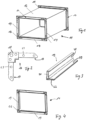
Bevorzugt ist vorgesehen, dass das zumindest eine Wandelement einen Grundrahmen und einen Tragrahmen aufweist, die vorzugsweise L-förmig zueinander ausgerichtet sind. Dies ermöglicht zum einen eine einfache Handhabung während einer Verfahrbewegung des Wandelementes und zum anderen eine hinreichende Aufnahmekapazität für die fertiggestellten Rahmen, um diese an den Aufhängevorrichtungen der Wandelemente zu positionieren.Provision is preferably made for the at least one wall element to have a base frame and a supporting frame which are preferably L-shaped are aligned to each other. On the one hand, this enables simple handling during a displacement movement of the wall element and, on the other hand, sufficient capacity for the finished frames in order to position them on the suspension devices of the wall elements.
Bevorzugt ist vorgesehen, dass jedes Wandelement zumindest eine Fixiereinrichtung und zumindest ein Sensorelement umfasst, um die Wandelemente zu einer geschlossenen Umhausung zu positionieren und diese Anordnung zu überwachen. Durch die Fixiervorrichtung können die Wandelemente untereinander und auch zur Umhausung für eine sichere Abschirmung des Arbeitsraumes fixiert werden. Gleichzeitig kann durch das zumindest eine Sensorelement erfasst werden, ob die Umhausung vollständig geschlossen ist, so dass aufgrund der Arbeitssicherheit erst darauffolgend ein Montageprozess beginnt.Provision is preferably made for each wall element to comprise at least one fixing device and at least one sensor element in order to position the wall elements in relation to a closed housing and to monitor this arrangement. With the fixing device, the wall elements can be fixed to each other and also to the housing for safe shielding of the work area. At the same time, the at least one sensor element can be used to detect whether the housing is completely closed, so that due to occupational safety, an assembly process only begins thereafter.
Bevorzugt ist in der Montagezelle ein Vorlagetisch vorgesehen, auf welchem Eckwinkel und/oder Flanschprofile aufgelegt werden, die durch eine optische Einrichtung in der Lage und Ausrichtung erkennbar sind und die mit der Mehrfachgreifvorrichtung ansteuerbar ist. Dies ist insbesondere vorgesehen, sofern die Eckwinkel und/oder Flanschprofile mit einer beliebigen Ausrichtung in einem Transportbehälter bereitgestellt werden.A template table is preferably provided in the assembly cell, on which corner brackets and/or flange profiles are placed, the position and alignment of which can be recognized by an optical device and which can be controlled with the multiple gripping device. This is intended in particular if the corner angles and/or flange profiles are provided with any orientation in a transport container.
Die der Erfindung zugrundeliegende Aufgabe wird des Weiteren durch eine Mehrfachgreifvorrichtung für eine Handhabungseinrichtung einer Montagezelle zur automatisierten Montage eines Rahmens, bestehend aus Flanschprofilen und Eckwinkeln, für ein Luftkanalelement gelöst, welche eine Anschlussstelle für die Aufnahme an der Handhabungseinrichtung aufweist, an die sich eine zylindrische Aufnahme anschließt und einen in der Längsmittelachse der Anschlussstelle drehbar ansteuerbaren Kopf aufweist, an welchem radial abstehend mehrere Flanschprofilgreifer zur Aufnahme von jeweils einem Flanschprofil vorgesehen sind und zumindest einen an dem Kopf vorgesehenen Eckwinkelgreifer zur Aufnahme von zumindest einem Eckwinkel aufweist, sowie eine Halteeinrichtung zur Aufnahme eines fertiggestellten Rahmens aus den Eckwinkeln und Flanschprofilen aufweist. Eine solche Mehrfachgreifvorrichtung weist den Vorteil auf, dass die erforderlichen Handhabungsschritte während der automatisierten Montage mit nur einer Greifvorrichtung durchgeführt werden kann, wodurch die Prozesszeiten erheblich reduziert werden können.The object on which the invention is based is also achieved by a multiple gripping device for a handling device of an assembly cell for the automated assembly of a frame, consisting of flange profiles and corner angles, for an air duct element, which has a connection point for the receptacle on the handling device, to which a cylindrical receptacle is attached connects and has a rotatably controllable head in the longitudinal center axis of the connection point, on which radially projecting several flange profile grippers are provided for receiving one flange profile each and at least one corner angle gripper provided on the head for receiving of at least one corner angle, as well as having a holding device for receiving a finished frame from the corner angles and flange profiles. Such a multiple gripping device has the advantage that the necessary handling steps can be carried out during the automated assembly with only one gripping device, as a result of which the process times can be significantly reduced.
Bevorzugt ist ein Prägewerkzeug an der Mehrfachgreifvorrichtung vorgesehen. Dieses Prägewerkzeug ist vorteilhafterweise in der Längsmittelachse der Anschlussstelle und dieser gegenüberliegend das Prägewerkzeug ausgerichtet. Diese Anordnung ermöglicht, dass die Kraftrichtung für das Prägewerkzeug in einer Achse der Handhabungseinrichtung liegt, so dass keine Hebelkräfte während des Einbringens der Prägewerkzeuge entstehen und somit ein einfacher Aufbau der Mehrfachgreifvorrichtung ermöglicht ist.An embossing tool is preferably provided on the multiple gripping device. This embossing tool is advantageously aligned in the longitudinal center axis of the connection point and the embossing tool is opposite this. This arrangement makes it possible for the direction of force for the embossing tool to lie in an axis of the handling device, so that no leverage forces arise during the introduction of the embossing tools, and a simple construction of the multiple gripping device is thus made possible.
Bevorzugt ist vorgesehen, dass der Eckwinkelgreifer als Magnetgreifer mit zumindest einem Haltedorn ausgebildet ist. Ein solcher Haltedorn kann beispielsweise in eine Befestigungsbohrung im Mittelteil des Eckwinkels eingreifen und durch die Magnetkraft den Eckwinkel aufnehmen.Provision is preferably made for the corner angle gripper to be designed as a magnetic gripper with at least one holding mandrel. Such a holding mandrel can, for example, engage in a fastening hole in the central part of the corner bracket and receive the corner bracket by the magnetic force.
Bevorzugt ist vorgesehen, dass die Länge des zumindest einen Haltedorns für die Aufnahme der Anzahl der für den Rahmen erforderlichen Eckwinkel ausgebildet ist. Dadurch können mehrere Eckwinkel insbesondere deckungsgleich aneinanderliegend von dem Eckwinkelgreifer aufgenommen werden und aufeinanderfolgend in Formnester der Eckwinkelaufnahmen an der Montagevorrichtung abgelegt werden.It is preferably provided that the length of the at least one retaining mandrel is designed to accommodate the number of corner brackets required for the frame. As a result, several corner brackets can be picked up by the corner bracket gripper, in particular congruently, and placed one after the other in mold cavities of the corner bracket brackets on the assembly device.
Des Weiteren ist bevorzugt vorgesehen, dass der Eckwinkelgreifer zumindest ein Anschlagselement zur lagerichtigen Ausrichtung und Aufnahme des zumindest einen Eckwinkels aufweist. Dadurch kann eine definierte Ansteuerung der Lage für die Positionierung der Eckwinkel in den Eckwinkelaufnahmen der Montagevorrichtung erfolgen.Furthermore, it is preferably provided that the corner angle gripper has at least one stop element for correctly aligning and receiving the at least one corner angle. As a result, the position for positioning the corner brackets in the corner bracket receptacles of the assembly device can be controlled in a defined manner.
Alternativ und bevorzugt ist vorgesehen, dass zwei mit Abstand zueinander angeordnete Haltedorne vorgesehen werden. Dadurch kann bereits eine definierte Ausrichtung der Eckwinkel ermöglicht sein. Dabei kann jeder Haltedorn in eine Befestigungsbohrung eines Einsteckfingers des Eckwinkels eingreifen.Alternatively and preferably, it is provided that two holding mandrels arranged at a distance from one another are provided. A defined alignment of the corner brackets can already be made possible as a result. Each retaining mandrel can engage in a mounting hole of an insertion finger of the corner bracket.
An dem Kopf der Mehrfachgreifvorrichtung ist bevorzugt die Anzahl von Flanschprofilgreifern vorgesehen, welche der Anzahl an Flanschprofilen für die Herstellung des Rahmens entspricht. Diese Flanschprofilgreifer nehmen die Flanschprofile vorzugsweise koaxial zur Längsmittelachse der Anschlussstelle auf.The number of flange profile grippers that corresponds to the number of flange profiles for the production of the frame is preferably provided on the head of the multiple gripping device. These flange profile grippers preferably pick up the flange profiles coaxially to the longitudinal center axis of the connection point.
Des Weiteren ist bevorzugt vorgesehen, dass die Flanschprofilgreifer als Magnetgreifer ausgebildet sind. Dadurch ist eine konstruktiv einfach ausgebildete als auch einfach ansteuerbare Greiferanordnung ermöglicht.Furthermore, it is preferably provided that the flange profile grippers are designed as magnetic grippers. As a result, a gripper arrangement that is simple in terms of construction and can also be controlled in a simple manner is made possible.
Bevorzugt ist vorgesehen, dass die Flanschprofilgreifer in einem Winkel von 180° oder weniger aneinandergereiht an dem Kopf angeordnet sind und der Eckwinkelgreifer diesem Aufnahmebereich gegenüberliegend ausgerichtet ist. Dadurch kann sowohl eine störungsfreie Aufnahme der Flanschprofile und Eckwinkel aus dem Magazin oder dem Vorlagetisch erfolgen sowie eine einfache aufeinanderfolgende Positionierung der Eckwinkel und Flanschprofile in der Montagevorrichtung erfolgen.Provision is preferably made for the flange profile grippers to be arranged in a row on the head at an angle of 180° or less and for the corner angle gripper to be aligned opposite this receiving area. This means that the flange profiles and corner brackets can be picked up from the magazine or the template table without any problems, and the corner brackets and flange sections can be positioned in the assembly device in a simple, sequential manner.
Die an der Mehrfachgreifvorrichtung angeordnete Halteeinrichtung umfasst bevorzugt zwei mit Abstand zueinander angeordnete Haltelaschen, die vorzugsweise an deren stirnseitigem Ende eine Abrutschsicherung aufweist. Durch die zwei mit Abstand ausgerichteten Haltelaschen kann ein sicheres Greifen des fertiggestellten Rahmens ermöglicht sein, um diesen aus den Eckwinkelaufnahmen und Flanschprofilaufnahmen herauszuführen. Gleichzeitig kann dadurch eine definierte Übergabe und Ausrichtung des Rahmens an die Aufhängeeinrichtung an dem Wandelement ermöglicht sein.The holding device arranged on the multiple gripping device preferably comprises two holding lugs which are arranged at a distance from one another and which preferably have an anti-slip device on their front end. The two spaced-apart retaining tabs can enable the finished frame to be gripped securely in order to guide it out of the corner angle mounts and flange profile mounts. At the same time, a defined transfer and alignment of the frame to the suspension device on the wall element can thereby be made possible.
Die Erfindung sowie weitere vorteilhafte Ausführungsformen und Weiterbildungen derselben werden im Folgenden anhand der in den Zeichnungen dargestellten Beispiele näher beschrieben und erläutert. Die der Beschreibung und den Zeichnungen zu entnehmenden Merkmale können einzeln für sich oder zu mehreren in beliebiger Kombination erfindungsgemäß angewandt werden. Es zeigen:
Figur 1- eine perspektivische Ansicht eines bekannten Luftkanalelementes,
- Figur 2
- eine schematische Ansicht auf einen Eckwinkel gemäß
Figur 1 , - Figur 3
- eine perspektivische Ansicht eines Flanschprofils des Luftkanalelementes gemäß
Figur 1 , - Figur 4
- eine perspektivische Ansicht eines Rahmens für das
Luftkanalelement gemäß Figur 1 , Figur 5- eine perspektivische Ansicht einer Montagezelle,
Figur 6- eine schematische Seitenansicht auf eine Mehrfachgreifvorrichtung für eine Handhabungseinrichtung,
Figur 7- eine weitere schematische Seitenansicht der Mehrfachgreifvorrichtung gemäß
Figur 6 , Figur 8- eine schematische Ansicht von oben auf die
Mehrfachgreifvorrichtung gemäß Figur 6 , Figur 9- eine weitere schematische Seitenansicht der Mehrfachgreifvorrichtung gemäß
Figur 6 , - Figur 10
- eine perspektivische Ansicht einer Montagevorrichtung für eine Montagezelle gemäß
Figur 5 , Figur 11- eine schematisch vergrößerte Ansicht von oben auf Eckwinkelaufnahmen und eine Flanschaufnahme der Montagevorrichtung gemäß
Figur 10 , - Figuren 12 - 14
- schematische Ansichten von Arbeitsschritten für eine automatisierte Montage des Rahmens gemäß
Figur 4 , - Figur 15
- eine perspektivische Ansicht der Umhausung gemäß
Figur 5 , Figur 16- eine schematische Ansicht von oben auf die Umhausung gemäß
Figur 15 , und Figur 17- eine perspektivische Ansicht eines Wandelementes für die Umhausung gemäß
Figur 15 .
- figure 1
- a perspective view of a known air duct element,
- figure 2
- according to a schematic view of a corner bracket
figure 1 , - figure 3
- a perspective view of a flange profile of the air duct element according to FIG
figure 1 , - figure 4
- a perspective view of a frame for the air duct element according to FIG
figure 1 , - figure 5
- a perspective view of an assembly cell,
- figure 6
- a schematic side view of a multiple gripping device for a handling device,
- figure 7
- a further schematic side view of the multiple gripping device according to FIG
figure 6 , - figure 8
- a schematic view from above of the multiple gripping device according to FIG
figure 6 , - figure 9
- a further schematic side view of the multiple gripping device according to FIG
figure 6 , - figure 10
- a perspective view of an assembly device for an assembly cell according to
figure 5 , - figure 11
- a schematically enlarged top view of corner angle shots and a flange shot of the mounting device according to FIG
figure 10 , - Figures 12 - 14
- Schematic views of work steps for an automated assembly of the frame according to
figure 4 , - figure 15
- a perspective view of the enclosure according to FIG
figure 5 , - figure 16
- a schematic view from above of the enclosure according to FIG
figure 15 , and - figure 17
- a perspective view of a wall element for the enclosure according to
figure 15 .
In
In
In
In
In
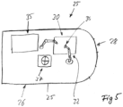
Die Umhausung 26 umgibt einen Arbeitsraum. In diesem Arbeitsraum ist eine Montagevorrichtung 30 vorgesehen, durch welche die Eckwinkel 16 und die Flanschprofile 19 zusammengesteckt werden, um den Rahmen 14 gemäß
Benachbart zur Montagemaschine 30 ist ein Magazin 35 oder sind mehrere Magazine 35 vorgesehen, durch welche die Flanschprofile 19 und die Eckwinkel 16 zur Verarbeitung bereitgestellt werden. Des Weiteren kann in der Montagezelle 25 ein Vorlagetisch 37 vorgesehen sein. Auf diesen Vorlagetisch 37 können Eckwinkel 16 und/oder Flanschprofile 19 aufgelegt werden, damit darauffolgend das Mehrfachgreifelement 34 in einer definierten Lage und Ausrichtung die Eckwinkel 16 und/oder Flanschprofile 19 aufnimmt. Auch kann das Mehrfachgreifelement 34 Eckwinkel 16 und/oder Flanschprofile 19 unmittelbar aus dem oder den Magazinen 35 entnehmen.A
Bei dieser Montagezelle 25 kann eine weitere Handhabungseinrichtung 32 vorgesehen sein, welche Eckwinkel 16 und/oder Flanschprofile 19 aus dem oder den Magazinen 35 entnimmt und auf den Vorlagetischen 37 bereitstellt. Die Handhabungseinrichtung 32 entnimmt dann die bereitgestellten Eckwinkel 16 und/oder Flanschprofile 19 von dem Vorlagetisch 37 und führt diese in die Montagevorrichtung 30 über. Nach der Montage des Rahmens 14 wird der fertiggestellte Rahmen 14 durch das Mehrfachgreifelement 34 der Handhabungseinrichtung 32 aus der Montagevorrichtung 30 entnommen. Von der Montagevorrichtung 30 wird der fertiggestellte Rahmen 14 an einen Speicher 31 übergeführt. Im Ausführungsbeispiel stellen die Wandelemente 28 den Speicher 31 dar. Die fertiggestellten Rahmen 14 werden an Aufhängeeinrichtungen 29 der Wandelemente 28 positioniert.A
Sofern eine zusätzliche Handhabungseinrichtung nicht vorhanden ist, entnimmt die Handhabungseinrichtung 32 Eckwinkel 16 und/oder Flanschprofile 19 aus den Magazinen 35 und positioniert diese ggf. auf dem Vorlagetisch 37 und werden von dort aus der Montagevorrichtung 30 zugeführt. Sofern die Eckwinkel 16 und/oder die Flanschprofile 19 in einer definierten Lage den Magazinen 35 entnommen werden können, werden die Eckwinkel 16 und/oder die Flanschprofile 19 direkt in die Montagevorrichtung 30 übergeführt.If an additional handling device is not available, the handling
In
Diese Mehrfachgreifvorrichtung 34 umfasst eine Anschlussstelle 41, die mit einer Schnittstelle der Handhabungseinrichtung 32 verbindbar ist. Dadurch wird sowohl eine mechanische als auch eine elektrische Verbindung zur Ansteuerung der Mehrfachgreifvorrichtung 34 gebildet. Von der Anschlussstelle 41 aus erstreckt sich eine zylindrische Aufnahme 42, an welcher rotierend ein Kopf 44 befestigt ist. An diesem Kopf 44 sind Flanschprofilgreifer 45 radial nach außen weisend positioniert. Diese Flanschprofilgreifer 45 sind gemäß
Den Flanschprofilgreifern 45 gegenüberliegend ist ein Eckwinkelgreifer 51 vorgesehen. Dieser Eckwinkelgreifer 51 weist zumindest einen, vorzugsweise zwei, Haltedorne 52 auf. Dieser Haltedorn 52 ist in der Geometrie an eine Befestigungsbohrung 53 im Mittelteil 18 oder im Einsteckfinger 17 des Eckwinkels 16 angepasst. Der Haltedorn 52 greift zur Aufnahme der Eckwinkel 16 in die Befestigungsbohrung 53 ein. Die Eckwinkel 16 werden durch eine Magnethaltekraft zum Haltedorn 52 befestigt. Bevorzugt ist vorgesehen, dass durch die Länge des Haltedorns 52 vier aneinanderliegende Eckwinkel 16 gleichzeitig gehalten werden können. An der zylindrischen Aufnahme 42 ist des Weiteren eine Halteeinrichtung 55 vorgesehen. Diese Halteeinrichtung 55 umfasst zwei im Abstand zueinander angeordnete Haltelaschen 56. Diese Haltelaschen 56 sind bevorzugt parallel zueinander ausgerichtet. Am freien stirnseitigen Ende der Haltelaschen 56 ist eine Abrutschsicherung 57 vorgesehen.A
Die
In
In der in
In
90° versetzt zueinander. Bevorzugt ist die erste Linearachsenanordnung 62 in Y-Richtung verfahrbar und die zweite Linearachsenanordnung 72 in X-Richtung verfahrbar. Dies kann auch vertauscht sein. Durch die übereinanderliegende Zuordnung der ersten und zweiten Linearachsenanordnung 62, 72 kann eine Kreuztischanordnung geschaffen werden, durch welche die Montage der Eckwinkel 16 zu den Flanschprofilen 19 ermöglicht ist. Diese Kreuztischanordnung weist für jede Eckwinkelaufnahme 67 einen Kreuztisch auf.90° offset to each other. The first linear axis arrangement 62 can preferably be moved in the Y direction and the second
Die erste Linearachsenanordnung 62 umfasst eine mittlere Linearachse 65 sowie jeweils eine äußere Linearachse 63, 65. Jede dieser Linearachsen ist bevorzugt aus zwei Linearantrieben 66 gebildet, die in Reihe zueinander angeordnet sind.The first linear axis arrangement 62 comprises a central
Die zweite Linearachsenanordnung 72 weist einen analogen Aufbau auf. Diese zweite Linearachsenanordnung 72 weist eine innere Linearachse 74 und eine äußere Linearachse 73, 75 auf. Diese Linearachsen 73, 74, 75 werden ebenfalls durch zwei Linearantriebe 66 ausgebildet, die in Reihe zueinander angeordnet sind.The second
Durch die über Kreuz angeordneten Linearantriebe 66 der äußeren Linearachsen 63, 73 und 65, 75 werden diese Kreuztische gebildet. Auf diesen Kreuztischen sind die Eckwinkelaufnahmen 67 positioniert.These cross tables are formed by the crossed
Den mittleren Linearachsen 64 sind die Flanschprofilaufnahmen 68 zugeordnet. Diese mittleren Linearachsen 64 ermöglichen nur eine Verfahrrichtung der Flanschprofilaufnahmen 68 in und entgegen der Y-Richtung. Die mittlere Linearachse 74 der zweiten Linearachsenanordnung 72 ermöglicht für die daran vorgesehene Flanschprofilaufnahme 68 nur eine Verfahrbewegung in und entgegen der X-Richtung.The flange profile mounts 68 are assigned to the central
Die Ansteuerung der ersten und zweiten Linearachsenanordnung 62, 72 erfolgt über eine Steuerung 77. Diese Steuerung 77 ist mit einer Steuerung für die Handhabungseinrichtung 32 und der Mehrfachgreifvorrichtung 34 gekoppelt oder beinhaltet diese. Diese Steuerung kann auch Teil der Steuerung sein, welche die gesamte Montagezelle 25 überwacht und die einzelnen Komponenten in der Montagezelle 25 ansteuert.The first and second
In
Die Flanschprofilaufnahme 68 kann ein U-förmiges Formnest 79 umfassen. Diesem Formnnest 79 kann wiederum ein ansteuerbarer Haltemagnet zugeordnet werden, so dass das eingelegte Flanschprofil 19 durch die Magnetkraft in deren Ausrichtung gehalten wird.The
Zur Montage der Eckwinkel 16 und/oder Flanschprofile 19 mit der Montagevorrichtung 30 wird auf die
Nach dem Bestücken der Eckwinkelaufnahmen 67 mit Eckwinkeln 16 und der Flanschprofilaufnahmen 68 mit Flanschprofilen 19 wird die zweite Linearachsenanordnung 72 angesteuert, so dass die Eckwinkelaufnahmen 67 in und entgegen der X-Richtung auf die jeweiligen Flanschprofile 19 zubewegt werden. Dabei werden die Einsteckfinger 17 in die erste Kammer 21 der Flanschprofile 19 eingesteckt und eine Montagegruppe 81 gebildet. Diese Montagegruppe 81 besteht aus zwei in das Flanschprofil 19 eingesteckten Eckwinkeln 16. Darauffolgend wird die erste Linearachsenanordnung 62 für eine Verfahrbewegung in und entgegen der Y-Richtung angesteuert, so dass die jeweils freien Einsteckfinger 17 der Eckwinkel 16 in das dritte und vierte Flanschprofil 19 eingesteckt werden. Dies zeigt
In
Die Wandelemente 28 weisen eine Doppelfunktion auf. Zum einen bilden diese einen Teil der Umhausung 26, haben also die Funktion wie die Schutzwände 27, zum anderen übernehmen diese die Funktion des Speichers 31. Hierfür sind an einer Innenseite der Wandelemente 28 Aufhängeeinrichtungen 29 vorgesehen. An diesen Aufhängeeinrichtungen 29 können die fertiggestellten Rahmen 14 durch die Mehrfachgreifvorrichtung 34 mit dem aufgenommenen Rahmen 14, wie dies in
Am Wandelement 28, vorzugsweise an dessen Grundrahmen 87, ist zumindest ein Fixierelement 89 vorgesehen, um das Wandelement 28 in einer gesicherten Position zur Umhausung 26 zu halten. Vorteilhafterweise ist an dem Wandelement 28, insbesondere dem Grundrahmen 87, zumindest ein Sensorelement 91 vorgesehen. Dadurch kann abgefragt werden, ob alle Wandelemente 28 zur Bildung einer geschlossenen Umhausung 26 vorhanden und/oder zueinander fixiert sind, bevor ein automatisierter Montageprozess gestartet wird.At least one fixing
Die Wandelemente 28 können nach der Bestückung mit mehreren Rahmen 14 aus der Umhausung 26 gelöst werden und zu einem weiteren Arbeitsplatz oder einer weiteren Arbeitsstation übergeführt werden. Weitere unbestückte Wandelemente 28 können zur Komplettierung der Umhausung 26 wieder positioniert werden, um darauffolgend die automatische Montage von Rahmen 14 zeitnah fortzuführen.After being equipped with
Claims (16)
Applications Claiming Priority (1)
| Application Number | Priority Date | Filing Date | Title |
|---|---|---|---|
| DE102021126966.0A DE102021126966A1 (en) | 2021-10-18 | 2021-10-18 | Method, assembly device, assembly cell and multiple gripping device for the automated assembly of a frame for an air duct element |
Publications (2)
| Publication Number | Publication Date |
|---|---|
| EP4166864A2 true EP4166864A2 (en) | 2023-04-19 |
| EP4166864A3 EP4166864A3 (en) | 2023-06-21 |
Family
ID=83689994
Family Applications (1)
| Application Number | Title | Priority Date | Filing Date |
|---|---|---|---|
| EP22200586.0A Pending EP4166864A3 (en) | 2021-10-18 | 2022-10-10 | Method, assembly device, assembly cell and multi-grip device for automated assembly of a frame for an air duct element |
Country Status (2)
| Country | Link |
|---|---|
| EP (1) | EP4166864A3 (en) |
| DE (1) | DE102021126966A1 (en) |
Cited By (1)
| Publication number | Priority date | Publication date | Assignee | Title |
|---|---|---|---|---|
| CN116652547A (en) * | 2023-07-31 | 2023-08-29 | 济南天辰智能装备股份有限公司 | Automatic door and window corner connector installation equipment |
Citations (1)
| Publication number | Priority date | Publication date | Assignee | Title |
|---|---|---|---|---|
| EP3425251B1 (en) | 2017-07-03 | 2019-08-14 | Jörg-Peter Mez | Air duct connection system |
Family Cites Families (4)
| Publication number | Priority date | Publication date | Assignee | Title |
|---|---|---|---|---|
| US5621956A (en) * | 1994-01-10 | 1997-04-22 | Ward Industries, Inc. | Duct frame assembly apparatus |
| US5649347A (en) * | 1995-12-29 | 1997-07-22 | Cattadoris; Joseph M. | Apparatus for use in assembling a frame |
| US7013545B1 (en) * | 2003-04-18 | 2006-03-21 | Ritchie Robert J | Compact duct corner installation tool |
| CA2868557C (en) * | 2013-03-15 | 2018-10-02 | Hvac Inventors/Systemation, Inc. | Apparatus and method for placement of angle plates in transverse duct flanges |
-
2021
- 2021-10-18 DE DE102021126966.0A patent/DE102021126966A1/en active Pending
-
2022
- 2022-10-10 EP EP22200586.0A patent/EP4166864A3/en active Pending
Patent Citations (1)
| Publication number | Priority date | Publication date | Assignee | Title |
|---|---|---|---|---|
| EP3425251B1 (en) | 2017-07-03 | 2019-08-14 | Jörg-Peter Mez | Air duct connection system |
Cited By (2)
| Publication number | Priority date | Publication date | Assignee | Title |
|---|---|---|---|---|
| CN116652547A (en) * | 2023-07-31 | 2023-08-29 | 济南天辰智能装备股份有限公司 | Automatic door and window corner connector installation equipment |
| CN116652547B (en) * | 2023-07-31 | 2023-12-05 | 济南天辰智能装备股份有限公司 | Automatic door and window corner connector installation equipment |
Also Published As
| Publication number | Publication date |
|---|---|
| DE102021126966A1 (en) | 2023-04-20 |
| EP4166864A3 (en) | 2023-06-21 |
Similar Documents
| Publication | Publication Date | Title |
|---|---|---|
| AT510409B1 (en) | MANUFACTURING DEVICE WITH TOOL POSITION DETECTION MEANS AND METHOD OF OPERATING THEREOF | |
| EP1716991B1 (en) | Manufacturing system for plate-shaped workpieces | |
| DE102009018619A1 (en) | robot support | |
| EP2625748B1 (en) | Method for mounting components on a supporting rail, and system for carrying out the method | |
| AT519014B1 (en) | Production plant with manipulation device | |
| WO2007073901A2 (en) | Bending machine comprising a multi-shaft robot for positioning sheet metal workpieces | |
| EP0440318B1 (en) | Manipulator and process for manipulating workpieces | |
| EP2881219B1 (en) | Tool exchange apparatus for use in a machining centre and machining centre for machining a workpiece | |
| EP0215263B1 (en) | Press brake | |
| DE60219267T2 (en) | Gripping unit for the automated machining of workpieces, and apparatus and method with such a unit | |
| EP4166864A2 (en) | Method, assembly device, assembly cell and multi-grip device for automated assembly of a frame for an air duct element | |
| DE102019212341A1 (en) | Device for changing bending tools in a bending machine for bending sheet metal | |
| EP2532456B1 (en) | Bending machine and bending tool | |
| AT398918B (en) | SHEET MANIPULATOR FOR A BENDING PRESS | |
| EP2944390B1 (en) | Bending tool and method for changing tool | |
| EP3527325A1 (en) | Processing assembly for machining workpieces | |
| EP2916994B1 (en) | Manufacturing plant for producing an assembly consisting of a plurality of components | |
| EP3031572A1 (en) | Tool exchange apparatus for use in a machining centre and machining centre for machining a workpiece | |
| EP0918592B1 (en) | Production and/or mounting device | |
| EP0427215B1 (en) | Notching apparatus | |
| EP4223449A1 (en) | Method, mounting device, mounting cell and multiple gripping device for the automatic mounting of a frame for an air channel element | |
| DE102017209688A1 (en) | Transport device for components for transporting within a workstation | |
| DE102015001262B4 (en) | Method for producing at least approximately rotationally symmetrical assembly components | |
| EP2274114B1 (en) | Transporting apparatus with positioning stop | |
| DE102015219446B3 (en) | Shell construction plant with adjustable equipment tables at at least one set-up station and method for producing two mutually different manufacturing components in a shell construction plant |
Legal Events
| Date | Code | Title | Description |
|---|---|---|---|
| PUAI | Public reference made under article 153(3) epc to a published international application that has entered the european phase |
Free format text: ORIGINAL CODE: 0009012 |
|
| STAA | Information on the status of an ep patent application or granted ep patent |
Free format text: STATUS: THE APPLICATION HAS BEEN PUBLISHED |
|
| AK | Designated contracting states |
Kind code of ref document: A2 Designated state(s): AL AT BE BG CH CY CZ DE DK EE ES FI FR GB GR HR HU IE IS IT LI LT LU LV MC ME MK MT NL NO PL PT RO RS SE SI SK SM TR |
|
| PUAL | Search report despatched |
Free format text: ORIGINAL CODE: 0009013 |
|
| AK | Designated contracting states |
Kind code of ref document: A3 Designated state(s): AL AT BE BG CH CY CZ DE DK EE ES FI FR GB GR HR HU IE IS IT LI LT LU LV MC ME MK MT NL NO PL PT RO RS SE SI SK SM TR |
|
| RIC1 | Information provided on ipc code assigned before grant |
Ipc: B25J 1/00 20060101ALI20230512BHEP Ipc: B23P 19/04 20060101ALI20230512BHEP Ipc: B21D 53/74 20060101ALI20230512BHEP Ipc: F16L 23/14 20060101ALI20230512BHEP Ipc: F24F 13/02 20060101AFI20230512BHEP |
|
| STAA | Information on the status of an ep patent application or granted ep patent |
Free format text: STATUS: REQUEST FOR EXAMINATION WAS MADE |
|
| 17P | Request for examination filed |
Effective date: 20231221 |
|
| RBV | Designated contracting states (corrected) |
Designated state(s): AL AT BE BG CH CY CZ DE DK EE ES FI FR GB GR HR HU IE IS IT LI LT LU LV MC ME MK MT NL NO PL PT RO RS SE SI SK SM TR |