EP1716991B1 - Manufacturing system for plate-shaped workpieces - Google Patents
Manufacturing system for plate-shaped workpieces Download PDFInfo
- Publication number
- EP1716991B1 EP1716991B1 EP06002342A EP06002342A EP1716991B1 EP 1716991 B1 EP1716991 B1 EP 1716991B1 EP 06002342 A EP06002342 A EP 06002342A EP 06002342 A EP06002342 A EP 06002342A EP 1716991 B1 EP1716991 B1 EP 1716991B1
- Authority
- EP
- European Patent Office
- Prior art keywords
- manufacturing system
- extension arm
- gripping
- machining centre
- machining center
- Prior art date
- Legal status (The legal status is an assumption and is not a legal conclusion. Google has not performed a legal analysis and makes no representation as to the accuracy of the status listed.)
- Active
Links
- 238000004519 manufacturing process Methods 0.000 title claims description 32
- 238000003754 machining Methods 0.000 claims description 19
- 230000008878 coupling Effects 0.000 claims description 6
- 238000010168 coupling process Methods 0.000 claims description 6
- 238000005859 coupling reaction Methods 0.000 claims description 6
- 238000012545 processing Methods 0.000 description 8
- 238000013461 design Methods 0.000 description 6
- 238000011161 development Methods 0.000 description 4
- 239000002023 wood Substances 0.000 description 4
- 238000010276 construction Methods 0.000 description 2
- 239000000463 material Substances 0.000 description 2
- 238000000034 method Methods 0.000 description 2
- 238000004891 communication Methods 0.000 description 1
- 230000000295 complement effect Effects 0.000 description 1
- 230000001419 dependent effect Effects 0.000 description 1
- 238000000151 deposition Methods 0.000 description 1
- 230000004927 fusion Effects 0.000 description 1
- 238000012423 maintenance Methods 0.000 description 1
- 238000012549 training Methods 0.000 description 1
Images

Classifications
-
- B—PERFORMING OPERATIONS; TRANSPORTING
- B23—MACHINE TOOLS; METAL-WORKING NOT OTHERWISE PROVIDED FOR
- B23Q—DETAILS, COMPONENTS, OR ACCESSORIES FOR MACHINE TOOLS, e.g. ARRANGEMENTS FOR COPYING OR CONTROLLING; MACHINE TOOLS IN GENERAL CHARACTERISED BY THE CONSTRUCTION OF PARTICULAR DETAILS OR COMPONENTS; COMBINATIONS OR ASSOCIATIONS OF METAL-WORKING MACHINES, NOT DIRECTED TO A PARTICULAR RESULT
- B23Q7/00—Arrangements for handling work specially combined with or arranged in, or specially adapted for use in connection with, machine tools, e.g. for conveying, loading, positioning, discharging, sorting
- B23Q7/04—Arrangements for handling work specially combined with or arranged in, or specially adapted for use in connection with, machine tools, e.g. for conveying, loading, positioning, discharging, sorting by means of grippers
-
- B—PERFORMING OPERATIONS; TRANSPORTING
- B25—HAND TOOLS; PORTABLE POWER-DRIVEN TOOLS; MANIPULATORS
- B25J—MANIPULATORS; CHAMBERS PROVIDED WITH MANIPULATION DEVICES
- B25J15/00—Gripping heads and other end effectors
- B25J15/0052—Gripping heads and other end effectors multiple gripper units or multiple end effectors
-
- B—PERFORMING OPERATIONS; TRANSPORTING
- B25—HAND TOOLS; PORTABLE POWER-DRIVEN TOOLS; MANIPULATORS
- B25J—MANIPULATORS; CHAMBERS PROVIDED WITH MANIPULATION DEVICES
- B25J5/00—Manipulators mounted on wheels or on carriages
- B25J5/02—Manipulators mounted on wheels or on carriages travelling along a guideway
-
- B—PERFORMING OPERATIONS; TRANSPORTING
- B25—HAND TOOLS; PORTABLE POWER-DRIVEN TOOLS; MANIPULATORS
- B25J—MANIPULATORS; CHAMBERS PROVIDED WITH MANIPULATION DEVICES
- B25J9/00—Programme-controlled manipulators
- B25J9/02—Programme-controlled manipulators characterised by movement of the arms, e.g. cartesian coordinate type
- B25J9/023—Cartesian coordinate type
-
- B—PERFORMING OPERATIONS; TRANSPORTING
- B27—WORKING OR PRESERVING WOOD OR SIMILAR MATERIAL; NAILING OR STAPLING MACHINES IN GENERAL
- B27C—PLANING, DRILLING, MILLING, TURNING OR UNIVERSAL MACHINES FOR WOOD OR SIMILAR MATERIAL
- B27C5/00—Machines designed for producing special profiles or shaped work, e.g. by rotary cutters; Equipment therefor
- B27C5/02—Machines with table
- B27C5/06—Arrangements for clamping or feeding work
-
- B—PERFORMING OPERATIONS; TRANSPORTING
- B23—MACHINE TOOLS; METAL-WORKING NOT OTHERWISE PROVIDED FOR
- B23Q—DETAILS, COMPONENTS, OR ACCESSORIES FOR MACHINE TOOLS, e.g. ARRANGEMENTS FOR COPYING OR CONTROLLING; MACHINE TOOLS IN GENERAL CHARACTERISED BY THE CONSTRUCTION OF PARTICULAR DETAILS OR COMPONENTS; COMBINATIONS OR ASSOCIATIONS OF METAL-WORKING MACHINES, NOT DIRECTED TO A PARTICULAR RESULT
- B23Q2240/00—Machine tools specially suited for a specific kind of workpiece
- B23Q2240/002—Flat workpieces
Definitions
- the invention relates to a manufacturing system with a machining center and a charging device according to the preamble of claim 1.
- a generic manufacturing system is for example from the EP 0 510 230 B1 and the EP 0 512 126 B1 known.
- a charging device is provided in addition to a machining center which has one or more spindles for machining plate-shaped workpieces made of wood, wood-based materials or the like.
- the feeder is movable along guide rails in a horizontally extending X-direction and has a gripping device by means of which the workpieces to be processed can be transferred from a conveyor belt to a chuck table of the processing center.
- the invention is based on the idea to achieve a simplified design and a reduced footprint of the entire manufacturing system by a partial merger of the machining center and the feeder.
- the first and the second arm ie the arm of the machining center and the arm of the charging device have a common guide device, along which they are displaceable in the X direction, and / or a common drive, by means of which they are movable in the X direction have.
- the fusion according to the invention also enables a simplified control of the entire manufacturing system.
- the common drive is provided in the machining center for moving the first arm in the horizontally extending X-direction.
- the charging device has a particularly lightweight and space-saving design, while the common drive can be used specifically for the various working movements of the boom of the machining center.
- the first arm and the second arm can be coupled to each other by means of a coupling device.
- the common drive boom of the machining center need only be coupled to the feeder during the loading operation, so that during normal machining operation of the machining center, its boom can operate freely and independently of the feeder, reducing the masses to be moved and thus high precision and machining speed of the machining center allowed.
- the coupling device can be configured in the context of the present invention in many ways, such as mechanical, electromagnetic, etc. According to a preferred embodiment of the present invention, however, it is provided that the coupling device, a first engagement element, which is provided on the first arm, and a second Engagement element, which is provided on the second arm has.
- a reliable coupling of the machining center and the charging device can be achieved in a simple manner, which can be easily solved if necessary. It is particularly advantageous if the two engagement elements can be brought into engagement with one another by loose engagement, since then the first extension arm can couple to the second delivery arm by means of a movement movement.
- the machining center and the charging device have a common drive
- a common control unit which is set up to control the operation of the Control machining center and the feeder simultaneously.
- the at least one gripping device in the Y direction and the Z direction, which extend substantially perpendicular to one another and substantially perpendicular to the X direction, independently from the other directions is movable.
- the second cantilever has at least three elongated portions, each of which extends in the X-direction, the Y-direction, and the Z-direction, which are substantially perpendicular to each other.
- the gripping device may in the context of the present invention have a variety of configurations which are suitable for securely gripping and lifting a plate-shaped workpiece. It has proven to be advantageous that the at least one gripping device each having a plurality of gripping elements, of which at least one is in each case pivotable. As below will be explained in more detail, the at least one, pivotable gripping element allows a speedy and precise application of the plate-shaped workpieces to a arranged in the machining center stop assembly.
- At least two gripping devices are provided, which are preferably arranged on opposite sides of the second arm.
- at least two workpieces can be fed simultaneously through the feed device to the machining center.
- the machining center has two independently movable main spindles in the Y and Z directions.
- two workpieces can be processed simultaneously, or it can edit a main spindle a workpiece, while the other main spindle performs a tool change for a subsequent machining operation.
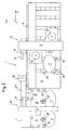
- Fig. 1 shows a schematic plan view of a manufacturing system 1 as a first embodiment of the present invention.
- the manufacturing system 1 comprises a machining center 10 for machining of plate-shaped workpieces 2, which preferably consist predominantly of wood or wood-based materials.
- the machining center 10 has a per se known construction with a first arm 12, which is displaceable along a guide rail 14 in a horizontally extending X-direction.
- On the boom 12, two main spindles 30, 32 are arranged on opposite sides, which are independent of each other in the in Fig. 1 specified Y-direction and in the perpendicular to the plane of Fig. 1 extending Z-direction are movable.
- the first boom 12 extends over a first workpiece table 34, which has an abutment device 36 for positioning workpieces to be machined and a clamping device, not shown, for holding the workpieces to be machined during the machining process.
- the manufacturing system 1 further comprises a loading device 20, which serves to feed the machining center 10 with plate-shaped workpieces 2, which are subsequently machined in the machining center 10, for example.
- the feeder 20 has a second boom 22, which in the present embodiment by three The second boom 22 is connected via its third portion 22 '''to the guide rail 14 so as to be slidable in the horizontally extending X-direction first portion 22 'of the second boom 22 in the present embodiment, a gripping device 24 is provided, which is movable in the Y-direction and in the Z-direction and is adapted to grip the plate-shaped workpieces 2 and release again.
- the gripping device 24 has a plurality of gripping elements 28, which are formed in the present embodiment by vacuum suction. Further, the gripping device 24 has a particularly ausgestaltetes gripping element 28 ', which can be pivoted about a provided with a spring and a stop switch hinge to align the plate-shaped workpieces 2 when depositing can, which will be described later in more detail.
- the third portion 22 "'of the second boom 22 has, at its end facing the machining center 10, an engagement member 18' intended to cooperate with a complementary first engagement member 18 provided on the first arm 12.
- the engagement elements may be, for example, elements that undergo a releasable mechanical engagement with each other, such as a pawl and a bolt. However, the engagement between these elements does not have to take place in a form-fitting manner, but can for example also be non-positive (for example by clamping elements), magnetically or in another suitable manner.
- the manufacturing system 1 according to the invention further comprises a control unit configured to simultaneously control the operation of the machining center 10 and the loading device 20. Using this control unit the operation of the manufacturing system 1 according to the invention takes place, for example, as follows.
- the gripping device 24 is moved over the stack of unprocessed workpieces 2 in the Y and Z directions in such a way that the gripping elements 28, 28 'can grip the upper side of the uppermost plate-shaped workpiece 2.
- the first boom 12 is moved in the direction of the loading device 20 in such a way that the first engagement element 18 and the second engagement element 18 'engage with one another.
- the machining center 10 and the loading device 20 are thus coupled together.
- This unit is now moved by operating the motor 16 along the guide rail 14 such that the workpiece to be machined 2 comes to rest above the workpiece table 34 near a desired processing position.
- the workpiece 2 is deposited by a method of the gripping device 24 on the workpiece table 34, and the gripping elements 28 are released from the workpiece 2, so that the workpiece only with the pivotable gripping element 28 'is in communication.
- the only held by the gripping member 28 'workpiece 2 is further pushed to the stop pin 36 of the workpiece table and thus brought precisely to the desired processing position.
- the gripping element 28 ' is pivoted against the force of the hinge spring (not shown) until a stop switch (not shown) is actuated, which ends the shifting operation.
- the workpiece 2 is held on the workpiece table 34 with a jig not shown in detail.
- the actual machining operation of the workpiece 2 is performed by the machining center 10 using machining tools that are loaded into the main spindles 30 and 32 respectively as needed.
- the machining process can basically also take place, or at least temporarily, with the feeding device 20 coupled to the machining center 10, it is preferred in the context of the present invention for the feeding device to be incorporated into the infeed device before the machining process begins Fig. 1 shown back home position and is released by separating the first and the second engagement element of the machining center 10.
- the feeder 20 is again coupled to the machining center 10 in the manner described above to subsequently receive the processed plate-shaped workpiece 2 'and on a corresponding stack for processed plate-shaped workpieces 2', for example, next to the stack for unprocessed plate-shaped workpieces can be arranged to take off. Thereafter, the loading operation described above starts again to prepare a subsequent machining operation.
- the workpiece table 34 has a plurality of suitable processing positions with corresponding stop elements 36, it is also possible to feed in each traversing movement of the loading device 20 an unprocessed plate-shaped workpiece 2 or to convey a processed plate-shaped workpiece 2 '.
- FIG Fig. 2 A manufacturing system 1 according to a second preferred embodiment of the present invention is shown schematically in FIG Fig. 2 shown.
- the embodiment shown differs from that in FIG Fig. 1 embodiment shown primarily in that the Charging device 20 has two gripping means 24, 26 which are arranged on opposite sides of the second arm 22. This makes it possible for the loading device 20 to deposit two or even more plate-shaped workpieces 2 on the workpiece table 34 during each movement or to pick up corresponding processed workpieces 2 'from the workpiece table 34.
- the operation of the manufacturing system in the second embodiment does not differ from those in the first embodiment.
Description
Die Erfindung betrifft ein Fertigungssystem mit einem Bearbeitungszentrum und einer Beschickungsvorrichtung nach dem Oberbegriff von Anspruch 1.The invention relates to a manufacturing system with a machining center and a charging device according to the preamble of claim 1.
Ein gattungsgemäßes Fertigungssystem ist beispielsweise aus der
Es ist Aufgabe der vorliegenden Erfindung, ein Fertigungssystem der eingangs genannten Art bereitzustellen, das bei einfacher Konstruktion einen verminderten Platzbedarf und einen leichten Zugriff auf den Bearbeitungsraum des Bearbeitungszentrums ermöglicht. Diese Aufgabe wird gemäß der vorliegenden Erfindung durch ein Fertigungssystem mit den Merkmalen von Anspruch 1 gelöst. Bevorzugte Weiterbildungen der Erfindung sind in den abhängigen Ansprüchen angegeben.It is an object of the present invention to provide a manufacturing system of the type mentioned above, which allows a reduced space requirement and easy access to the processing space of the machining center with a simple design. This object is achieved according to the present invention by a manufacturing system having the features of claim 1. Preferred embodiments of the invention are specified in the dependent claims.
Der Erfindung liegt der Gedanke zugrunde, durch eine teilweise Verschmelzung des Bearbeitungszentrums und der Beschickungsvorrichtung eine vereinfachte Konstruktion sowie einen verminderten Platzbedarf des gesamten Fertigungssystems zu erzielen. Zu diesem Zweck ist erfindungsgemäß vorgesehen, dass der erste und der zweite Ausleger, d.h. der Ausleger des Bearbeitungszentrums und der Ausleger der Beschickungsvorrichtung eine gemeinsame Führungseinrichtung, entlang derer sie in der X-Richtung verschiebbar sind, und/oder einen gemeinsamen Antrieb, mittels dessen sie in der X-Richtung verfahrbar sind, aufweisen.The invention is based on the idea to achieve a simplified design and a reduced footprint of the entire manufacturing system by a partial merger of the machining center and the feeder. For this purpose, it is provided according to the invention that the first and the second arm, ie the arm of the machining center and the arm of the charging device have a common guide device, along which they are displaceable in the X direction, and / or a common drive, by means of which they are movable in the X direction have.
Auf diese Weise kann beispielsweise vollständig auf die im Stand der Technik vorhandenen Führungsschienen und/oder Antriebseinheiten der Beschickungsvorrichtung verzichtet werden, was nicht nur die Konstruktion deutlich vereinfacht, sondern auch den Platzbedarf erheblich vermindert. Dabei ist zu beachten, dass beispielsweise bei einer gemeinsamen Führungseinrichtung keine Führungseinrichtung verwendet werden muss, die doppelt so groß bzw. lang ist, sondern die beiden Ausleger auf der gemeinsamen Führungseinrichtung derart angeordnet und betrieben werden können, dass ihre Bewegungsbereiche einander überschneiden und so eine deutlich verkleinerte Fläche für die Führungseinrichtung erzielt wird.In this way, for example, completely dispensed with existing in the prior art guide rails and / or drive units of the feeder, which not only significantly simplifies the construction, but also significantly reduces the space requirement. It should be noted that, for example, in a common guide device no guide device must be used, which is twice as long or long, but the two arms can be arranged and operated on the common guide device such that their ranges of movement overlap one another and so clearly reduced area is achieved for the guide device.
Durch diese Verschmelzung von Bearbeitungszentrum und Beschickungsvorrichtung wird darüber hinaus der Zugriff auf den Bearbeitungsraum des Bearbeitungszentrums deutlich erleichtert, was nicht nur ein gelegentliches manuelles Beschicken des Bearbeitungszentrums, sondern auch Wartungsarbeiten sowie Eingriffe bei Steuerungen und dergleichen deutlich erleichtert. Nicht zuletzt ermöglicht die erfindungsgemäße Verschmelzung auch eine vereinfachte Steuerung des gesamten Fertigungssystems. Diese Vorteile sind besonders ausgeprägt, wenn der erste und der zweite Ausleger sowohl eine gemeinsame Führungseinrichtung als auch einen gemeinsamen Antrieb aufweisen, was eine bevorzugte Ausführungsform der vorliegenden Erfindung darstellt.Through this merging of the machining center and the loading device access to the processing space of the machining center is also significantly easier, which not only an occasional manual loading of the machining center, but also facilitates maintenance and intervention in controls and the like. Not least, the fusion according to the invention also enables a simplified control of the entire manufacturing system. These advantages are particularly pronounced when the first and the second cantilever have both a common guide device and a common drive, which constitutes a preferred embodiment of the present invention.
Gemäß einer Weiterbildung der vorliegenden Erfindung ist der gemeinsame Antrieb in dem Bearbeitungszentrum zum Verfahren des ersten Auslegers in der sich horizontal erstreckenden X-Richtung vorgesehen. Mit dieser Anordnung wird erreicht, dass die Beschickungsvorrichtung eine besonders leichtgewichtige und platzsparende Konstruktion besitzt, während der gemeinsame Antrieb gezielt für die verschiedenen Arbeitsbewegungen des Auslegers des Bearbeitungszentrums genutzt werden kann. Dabei ist es besonders bevorzugt, dass der erste Ausleger und der zweite Ausleger mittels einer Kopplungseinrichtung miteinander koppelbar sind. In diesem Falle braucht der mit dem gemeinsamen Antrieb ausgestattete Ausleger des Bearbeitungszentrums nur während des Beschickungsvorganges mit der Beschickungsvorrichtung gekoppelt werden, so dass während des normalen Bearbeitungsbetriebes des Bearbeitungszentrums dessen Ausleger frei und unabhängig von der Beschickungsvorrichtung arbeiten kann, was die zu bewegenden Massen vermindert und somit eine hohe Präzision und Bearbeitungsgeschwindigkeit des Bearbeitungszentrums erlaubt.According to one embodiment of the present invention, the common drive is provided in the machining center for moving the first arm in the horizontally extending X-direction. With this arrangement it is achieved that the charging device has a particularly lightweight and space-saving design, while the common drive can be used specifically for the various working movements of the boom of the machining center. It is particularly preferred that the first arm and the second arm can be coupled to each other by means of a coupling device. In this case, the common drive boom of the machining center need only be coupled to the feeder during the loading operation, so that during normal machining operation of the machining center, its boom can operate freely and independently of the feeder, reducing the masses to be moved and thus high precision and machining speed of the machining center allowed.
Die Kopplungseinrichtung kann im Rahmen der vorliegenden Erfindung auf vielfältige Weise ausgestaltet sein, beispielsweise mechanisch, elektromagnetisch, etc. Gemäß einer bevorzugten Weiterbildung der vorliegenden Erfindung ist jedoch vorgesehen, dass die Kopplungseinrichtung ein erstes Eingriffselement, das an dem ersten Ausleger vorgesehen ist, und ein zweites Eingriffselement, das an dem zweiten Ausleger vorgesehen ist, aufweist. Hierdurch lässt sich auf einfache Weise eine zuverlässige Kopplung des Bearbeitungszentrums und der Beschickungsvorrichtung erzielen, die bei Bedarf auch problemlos wieder gelöst werden kann. Besonders vorteilhaft ist es, wenn die beiden Eingriffselemente durch loses Einrasten miteinander in Eingriff bringbar sind, da dann der erste Ausleger durch eine Verfahrbewegung den zweiten Ausleger ankoppeln kann.The coupling device can be configured in the context of the present invention in many ways, such as mechanical, electromagnetic, etc. According to a preferred embodiment of the present invention, however, it is provided that the coupling device, a first engagement element, which is provided on the first arm, and a second Engagement element, which is provided on the second arm has. As a result, a reliable coupling of the machining center and the charging device can be achieved in a simple manner, which can be easily solved if necessary. It is particularly advantageous if the two engagement elements can be brought into engagement with one another by loose engagement, since then the first extension arm can couple to the second delivery arm by means of a movement movement.
Insbesondere wenn das Bearbeitungszentrum und die Beschickungsvorrichtung einen gemeinsamen Antrieb aufweisen, ist es gemäß einer Weiterbildung der vorliegenden Erfindung bevorzugt, dass das Bearbeitungszentrum und die Beschickungsvorrichtung auch eine gemeinsame Steuereinheit aufweisen, die eingerichtet ist, den Betrieb des Bearbeitungszentrums und der Beschickungsvorrichtung simultan zu steuern. Hierdurch wird nicht nur der Konstruktionsaufwand mit entsprechenden Kosteneinsparungen vermindert, sondern es können auch Schnittstellenprobleme vermieden werden, die bei den bisher eingesetzten, getrennten Steuereinheiten für Beschickungsvorrichtung und Bearbeitungszentrum auftreten können. Auch die Komplexität der Steuersoftware wird hierdurch vermindert. Nicht zuletzt ergibt sich auch eine vereinfachte Bedienung bzw. ein verminderter Schulungsbedarf für das Bedienpersonal.In particular, if the machining center and the charging device have a common drive, it is preferred according to a development of the present invention that the machining center and the charging device also have a common control unit which is set up to control the operation of the Control machining center and the feeder simultaneously. As a result, not only the design effort is reduced with corresponding cost savings, but it can also interface problems can be avoided, which can occur in the previously used, separate control units for feeder and machining center. The complexity of the control software is thereby reduced. Last but not least, there is also a simplified operation or a reduced training requirement for the operating personnel.
Im Hinblick auf einen zügigen und flexiblen Beschickungsvorgang ist gemäß einer Weiterbildung der vorliegenden Erfindung vorgesehen, dass die mindestens eine Greifeinrichtung in der Y-Richtung und der Z-Richtung, die sich im Wesentlichen senkrecht zueinander sowie im Wesentlichen senkrecht zur X-Richtung erstrecken, unabhängig von den jeweils anderen Richtungen verfahrbar ist.With regard to a rapid and flexible charging process, it is provided according to a development of the present invention that the at least one gripping device in the Y direction and the Z direction, which extend substantially perpendicular to one another and substantially perpendicular to the X direction, independently from the other directions is movable.
Gemäß einer weiteren bevorzugten Ausführungsform der vorliegenden Erfindung besitzt der zweite Ausleger zumindest drei langgestreckte Abschnitte, von denen sich jeweils einer in der X-Richtung, der Y-Richtung und der Z-Richtung erstreckt, die im Wesentlichen senkrecht zueinander sind. Durch diese Ausgestaltung kann eine platzsparende, gemeinsame Führungseinrichtung realisiert werden, wobei der Ausleger mit seinen drei langgestreckten Abschnitten den Zugriff auf einem beispielsweise neben dem Bearbeitungszentrum vorgesehenen Werkstückstapel ermöglicht.According to another preferred embodiment of the present invention, the second cantilever has at least three elongated portions, each of which extends in the X-direction, the Y-direction, and the Z-direction, which are substantially perpendicular to each other. By this configuration, a space-saving, common guide device can be realized, wherein the boom with its three elongated sections allows access to an example provided next to the machining center workpiece stack.
Die Greifeinrichtung kann im Rahmen der vorliegenden Erfindung eine Vielzahl von Ausgestaltungen besitzen, die geeignet sind, ein plattenförmiges Werkstück sicher zu greifen und anzuheben. Dabei hat es sich als vorteilhaft erwiesen, dass die mindestens eine Greifeinrichtung jeweils eine Mehrzahl von Greifelementen aufweist, von denen jeweils mindestens eines verschwenkbar ist. Wie unten stehend noch ausführlicher erläutert werden wird, ermöglicht das mindestens eine, verschwenkbare Greifelement ein zügiges und präzises Anlegen der plattenförmigen Werkstücke an eine in dem Bearbeitungszentrum angeordnete Anschlaganordnung.The gripping device may in the context of the present invention have a variety of configurations which are suitable for securely gripping and lifting a plate-shaped workpiece. It has proven to be advantageous that the at least one gripping device each having a plurality of gripping elements, of which at least one is in each case pivotable. As below will be explained in more detail, the at least one, pivotable gripping element allows a speedy and precise application of the plate-shaped workpieces to a arranged in the machining center stop assembly.
Im Hinblick auf eine hohe Förderkapazität der Beschickungsvorrichtung bei gleichzeitig einfacher Konstruktion ist gemäß einer Weiterbildung der vorliegenden Erfindung vorgesehen, dass mindestens zwei Greifeinrichtungen vorgesehen sind, die bevorzugt auf gegenüberliegenden Seiten des zweiten Auslegers angeordnet sind. Hierdurch können mindestens zwei Werkstücke simultan durch die Beschickungsvorrichtung dem Bearbeitungszentrum zugeführt werden. Allerdings besteht auch die Möglichkeit, die Greifeinrichtungen derart auszugestalten, beispielsweise mit einer hohen Anzahl von Greifelementen, dass jeder der Greifeinrichtungen auch mehrere Werkstücke fördern kann.In view of a high conveying capacity of the charging device with a simple design is provided according to a development of the present invention that at least two gripping devices are provided, which are preferably arranged on opposite sides of the second arm. As a result, at least two workpieces can be fed simultaneously through the feed device to the machining center. However, it is also possible to design the gripping devices in such a way, for example with a high number of gripping elements, that each of the gripping devices can also convey a plurality of workpieces.
Um bei dem Bearbeitungszentrum des erfindungsgemäßen Fertigungssystems einen zügigen Arbeitsfortschritt und einen problemlosen Werkzeugwechsel zu ermöglichen, ist gemäß einer Weiterbildung der vorliegenden Erfindung vorgesehen, dass das Bearbeitungszentrum zwei unabhängig voneinander in Y- und Z-Richtung verfahrbare Hauptspindeln aufweist. Hierdurch können beispielsweise zwei Werkstücke simultan bearbeitet werden, oder es kann eine Hauptspindel ein Werkstück bearbeiten, während die andere Hauptspindel einen Werkzeugwechsel für einen nachfolgenden Bearbeitungsvorgang durchführt.In order to enable a rapid work progress and a problem-free tool change at the machining center of the manufacturing system according to the invention, it is provided according to a development of the present invention that the machining center has two independently movable main spindles in the Y and Z directions. As a result, for example, two workpieces can be processed simultaneously, or it can edit a main spindle a workpiece, while the other main spindle performs a tool change for a subsequent machining operation.
-
Fig. 1 zeigt schematisch eine Draufsicht einer ersten Ausführungsform des erfindungsgemäßen Fertigungssystems;Fig. 1 shows schematically a plan view of a first embodiment of the manufacturing system according to the invention; -
Fig. 2 zeigt schematisch eine Draufsicht einer zweiten Ausführungsform des erfindungsgemäßen Fertigungssystems.Fig. 2 schematically shows a plan view of a second embodiment of the manufacturing system according to the invention.
Bevorzugte Ausführungsformen der vorliegenden Erfindung werden nachfolgend ausführlich unter Bezugnahme auf die begleitenden Zeichnungen beschrieben.Preferred embodiments of the present invention will be described below in detail with reference to the accompanying drawings.
Das Fertigungssystem 1 umfasst ferner eine Beschickungsvorrichtung 20, die dazu dient, das Bearbeitungszentrum 10 mit plattenförmigen Werkstücken 2 zu beschicken, die anschließend in dem Bearbeitungszentrum 10 beispielsweise spanend bearbeitet werden. Die Beschickungsvorrichtung 20 besitzt einen zweiten Ausleger 22, der in der vorliegenden Ausführungsform durch drei langgestreckte Abschnitte 22', 22" und 22''' gebildet ist. Der zweite Ausleger 22 ist über seinen dritten Abschnitt 22''' derart mit der Führungsschiene 14 verbunden, dass er in der sich horizontal erstreckenden X-Richtung verschiebbar ist. An dem ersten Abschnitt 22' des zweiten Auslegers 22 ist in der vorliegenden Ausführungsform eine Greifeinrichtung 24 vorgesehen, die in der Y-Richtung und in der Z-Richtung verfahrbar und geeignet ist, die plattenförmigen Werkstücke 2 zu greifen und wieder frei zu geben.The manufacturing system 1 further comprises a
Die Greifeinrichtung 24 besitzt eine Mehrzahl von Greifelementen 28, die in der vorliegenden Ausführungsform durch Vakuumsauger gebildet sind. Ferner besitzt die Greifeinrichtung 24 ein besonders ausgestaltetes Greifelement 28', das über ein mit einer Feder und einem Anschlagschalter ausgestattetes Gelenk verschwenkt werden kann, um die plattenförmigen Werkstücke 2 beim Ablegen ausrichten zu können, was später noch eingehender beschrieben wird.The
Der dritte Abschnitt 22''' des zweiten Auslegers 22 besitzt an seinem dem Bearbeitungszentrum 10 zugewandten Ende ein Eingriffselement 18', das dazu vorgesehen ist, mit einem komplementären, ersten Eingriffselement 18 zusammenzuwirken, das an dem ersten Ausleger 12 vorgesehen ist. Bei den Eingriffselementen kann es sich beispielsweise um Elemente handeln, die einen lösbaren mechanischen Eingriff miteinander eingehen, wie beispielsweise eine Klinke und ein Bolzen. Allerdings muss der Eingriff zwischen diesen Elementen nicht formschlüssig erfolgen, sondern kann beispielsweise auch kraftschlüssig (beispielsweise durch Klemmelemente), magnetisch oder auf andere geeignete Weise erfolgen.The
Obgleich in den Figuren nicht gezeigt, umfasst das erfindungsgemäße Fertigungssystem 1 ferner eine Steuereinheit, die eingerichtet ist, den Betrieb des Bearbeitungszentrums 10 und der Beschickungseinrichtung 20 simultan zu steuern. Unter Einsatz dieser Steuereinheit vollzieht sich der Betrieb des erfindungsgemäßen Fertigungssystems 1 beispielsweise wie folgt.Although not shown in the figures, the manufacturing system 1 according to the invention further comprises a control unit configured to simultaneously control the operation of the
Zunächst wird die Greifeinrichtung 24 über den Stapel unbearbeiteter Werkstücke 2 in Y- und Z-Richtung derart verfahren, dass die Greifelemente 28, 28' die Oberseite des obersten plattenförmigen Werkstücks 2 greifen können. Simultan oder sequentiell hierzu wird der erste Ausleger 12 durch Betreiben des Antriebs 16 derart in Richtung der Beschickungsvorrichtung 20 verfahren, dass das erste Eingriffselement 18 und das zweite Eingriffselement 18' miteinander in Eingriff gelangen. Das Bearbeitungszentrum 10 und die Beschickungsvorrichtung 20 sind somit miteinander gekoppelt.First, the gripping
Diese Einheit wird nun durch Betreiben des Motors 16 entlang der Führungsschiene 14 derart verfahren, dass das zu bearbeitende Werkstück 2 oberhalb des Werkstücktisches 34 nahe einer gewünschten Bearbeitungsposition zum Liegen kommt. Nun wird das Werkstück 2 durch ein Verfahren der Greifeinrichtung 24 auf dem Werkstücktisch 34 abgelegt, und die Greifelemente 28 werden von dem Werkstück 2 gelöst, sodass das Werkstück nur noch mit dem schwenkbaren Greifelement 28' in Verbindung steht. Nun wird das nur noch durch das Greifelement 28' gehaltene Werkstück 2 weiter an die Anschlagbolzen 36 des Werkstücktisches herangeschoben und somit präzise in die gewünschte Bearbeitungsposition gebracht. Dabei wird das Greifelement 28' entgegen der Kraft der Gelenkfeder (nicht gezeigt) verschwenkt, bis ein Anschlagschalter (nicht gezeigt) betätigt wird, der den Verschiebevorgang beendet.This unit is now moved by operating the
Daraufhin wird das Werkstück 2 mit einer nicht näher gezeigten Aufspanneinrichtung an dem Werkstücktisch 34 festgehalten.Then, the
Nun erfolgt der eigentliche Bearbeitungsvorgang des Werkstücks 2 durch das Bearbeitungszentrum 10 unter Einsatz von Bearbeitungswerkzeugen, die in die Hauptspindeln 30 und 32 jeweils nach Bedarf eingewechselt werden.Now, the actual machining operation of the
Obgleich der Bearbeitungsvorgang grundsätzlich auch bzw. zumindest zeitweise mit an das Bearbeitungszentrum 10 angekoppelter Beschickungsvorrichtung 20 erfolgen kann, ist es im Rahmen der vorliegenden Erfindung bevorzugt, dass die Beschickungsvorrichtung vor Beginn des Bearbeitungsvorganges in die in
Nach Abschluss des Bearbeitungsvorganges wird die Beschickungsvorrichtung 20 erneut auf die oben beschriebene Weise an das Bearbeitungszentrum 10 angekoppelt, um anschließend das bearbeitete plattenförmige Werkstück 2' aufzunehmen und auf einem entsprechenden Stapel für bearbeitete plattenförmige Werkstücke 2', der beispielsweise neben dem Stapel für unbearbeitete plattenförmige Werkstücke angeordnet sein kann, abzulegen. Daraufhin beginnt der oben beschriebene Beschickungsvorgang erneut, um einen nachfolgenden Bearbeitungsvorgang vorzubereiten.After completion of the machining operation, the
Sofern der Werkstücktisch 34 über mehrere geeignete Bearbeitungspositionen mit entsprechenden Anschlagelementen 36 verfügt, ist es ebenso möglich, bei jeder Verfahrbewegung der Beschickungsvorrichtung 20 ein unbearbeitetes plattenförmiges Werkstück 2 einzufördern bzw. ein bearbeitetes plattenförmiges Werkstück 2' auszufördern.If the workpiece table 34 has a plurality of suitable processing positions with
Ein Fertigungssystem 1 gemäß einer zweiten bevorzugten Ausführungsform der vorliegenden Erfindung ist schematisch in
Claims (11)
- Manufacturing system (1) having
a machining centre (10) for cutting plate-like workpieces (2) possessing a first extension arm (12) which is displaceable in an X direction extending horizontally and comprises one or more spindles, and
a feeding device (20) for feeding the machining centre (10) with plate-like workpieces (2) comprising a second extension arm (22) which is displaceable in the X direction extending horizontally and at least one gripping device (24, 26) which is movable in a horizontally extending Y direction along the second extension arm (22) and in a vertically extending Z direction,
characterised in that
the first (12) and the second (22) extension arm have a common guide device (14) along which they are displaceable in the X direction and/or a common drive (16) by means of which they are movable in the X direction. - Manufacturing system according to claim 1, characterised in that the common drive (16) is provided in the machining centre (10) for moving the first extension arm (12) in the horizontally extending X direction.
- Manufacturing system according to claim 1 or 2, characterised in that the first extension arm (12) and the second extension arm (22) can be coupled to one another by means of a coupling device (18, 18').
- Manufacturing system according to claim 3, characterised in that the coupling device comprises a first engaging element (18) provided on the first extension arm (12) and a second engaging element (18') provided on the second extension arm (22).
- Manufacturing system according to any of the preceding claims, characterised in that the machining centre (10) and the feeding device (20) have a common control unit which is set up to control the operation of the machining centre (10) and the feeding device (20) simultaneously.
- Manufacturing system according to any of the preceding claims, characterised in that the at least single gripping device (24, 26) is movable in the Y direction and in the Z direction, which extend substantially perpendicular to one another and substantially perpendicular to the X direction, independently of the respective other directions.
- Manufacturing system according to any of the preceding claims, characterised in that the second extension arm (22) possesses three elongated sections (22', 22", 22"') of which one each extends in the X direction, Y direction and Z direction which are substantially perpendicular to one another.
- Manufacturing system according to any of the preceding claims, characterised in that the at least single gripping device (24, 26) comprises in each case a plurality of gripping elements (28) of which in each case one (28') is pivotable.
- Manufacturing system according to any of the preceding claims, characterised in that at least two gripping devices (24, 26) are provided which are preferably arranged on opposite sides of the second extension arm (22).
- Manufacturing system according to any of the preceding claims, characterised in that the machining centre comprises two main spindles (30, 32) movable independently of one another in the Y and Z direction.
- Manufacturing system according to any of the preceding claims, characterised in that the machining centre comprises a fixed workpiece bench (34) having a stop device (36) and a clamping device.
Priority Applications (1)
| Application Number | Priority Date | Filing Date | Title |
|---|---|---|---|
| PL06002342T PL1716991T3 (en) | 2005-04-29 | 2006-02-06 | Manufacturing system for plate-shaped workpieces |
Applications Claiming Priority (1)
| Application Number | Priority Date | Filing Date | Title |
|---|---|---|---|
| DE102005020119A DE102005020119B3 (en) | 2005-04-29 | 2005-04-29 | Woodworking system, for cutting board workpieces, has a work center with coupled radial arms at the feed and the work center with a horizontal sliding movement along the line of the assembly |
Publications (2)
| Publication Number | Publication Date |
|---|---|
| EP1716991A1 EP1716991A1 (en) | 2006-11-02 |
| EP1716991B1 true EP1716991B1 (en) | 2008-04-09 |
Family
ID=36441981
Family Applications (1)
| Application Number | Title | Priority Date | Filing Date |
|---|---|---|---|
| EP06002342A Active EP1716991B1 (en) | 2005-04-29 | 2006-02-06 | Manufacturing system for plate-shaped workpieces |
Country Status (4)
| Country | Link |
|---|---|
| EP (1) | EP1716991B1 (en) |
| DE (2) | DE102005020119B3 (en) |
| ES (1) | ES2304742T3 (en) |
| PL (1) | PL1716991T3 (en) |
Cited By (1)
| Publication number | Priority date | Publication date | Assignee | Title |
|---|---|---|---|---|
| DE102021125896A1 (en) | 2021-10-06 | 2023-04-06 | Ima Schelling Deutschland Gmbh | Plant, in particular a wood processing plant, for the processing and handling of panel-shaped workpieces |
Families Citing this family (14)
| Publication number | Priority date | Publication date | Assignee | Title |
|---|---|---|---|---|
| EP1892107B1 (en) | 2006-08-25 | 2009-11-04 | Homag Holzbearbeitungssysteme AG | Apparatus for printing a pattern on workpieces |
| ES2601398T3 (en) | 2006-03-08 | 2017-02-15 | Homag Holzbearbeitungssysteme Ag | Procedure and device for printing work pieces in plate form |
| US7914098B2 (en) | 2006-11-07 | 2011-03-29 | Homag Holzbearbeitungssysteme Ag | Device for patterning workpieces |
| DE502007002035D1 (en) | 2007-03-27 | 2009-12-31 | Homag Holzbearbeitungssysteme | Method for printing a three-dimensional container |
| EP1990150A1 (en) * | 2007-05-09 | 2008-11-12 | Weeke Bohrsysteme GmbH | Machining unit |
| DK2168714T3 (en) * | 2008-09-25 | 2013-09-16 | Weeke Bohrsysteme Gmbh | Feed and processing device |
| EP2423134B1 (en) | 2010-08-25 | 2013-03-13 | Grundner Sondermaschinen GmbH | Device for handling slab-like workpieces |
| DE102013216113A1 (en) | 2013-08-14 | 2015-03-05 | Homag Holzbearbeitungssysteme Gmbh | coating unit |
| CN108582291A (en) * | 2016-11-14 | 2018-09-28 | 宁波奉化飞天人精密模具设计有限公司 | A kind of timber cutting transport device |
| CN106426421A (en) * | 2016-11-30 | 2017-02-22 | 嘉善弘欣化工厂(普通合伙) | Stable equal-distance cutting device for building timber |
| DE102017208212A1 (en) | 2017-05-16 | 2018-11-22 | Homag Gmbh | Feeding device and feeding process |
| CN107097303B (en) * | 2017-05-18 | 2020-03-27 | 电子科技大学 | Position adjusting device for original timber processing |
| IT201900018485A1 (en) * | 2019-10-10 | 2021-04-10 | Scm Group Spa | Machining center comprising a piece loading and unloading system, piece loading and unloading system and method of operation of said machining center. |
| CN114311168A (en) * | 2021-12-21 | 2022-04-12 | 唐山市宝珠家具有限公司 | Full-automatic processing system for furniture products and processing method thereof |
Family Cites Families (4)
| Publication number | Priority date | Publication date | Assignee | Title |
|---|---|---|---|---|
| DE59103812D1 (en) * | 1991-04-25 | 1995-01-19 | Ligmatech Maschb Gmbh | Device for handling and processing plate-shaped workpieces made of wood, plastic, composite materials or the like. |
| ES2082033T3 (en) * | 1991-05-02 | 1996-03-16 | Ligmatech Maschb Gmbh | DEVICE FOR HANDLING PIECES IN THE FORM OF PLATES. |
| DE19601331C1 (en) * | 1996-01-16 | 1996-12-12 | Keusch Siegfried | Machine tool for flat wooden workpiece |
| DE19846819A1 (en) * | 1998-10-10 | 2000-04-13 | Biesse Spa | Board processing machine for furniture making, including work group movable sideways from working surface and at least one grip element |
-
2005
- 2005-04-29 DE DE102005020119A patent/DE102005020119B3/en not_active Expired - Fee Related
-
2006
- 2006-02-06 DE DE502006000584T patent/DE502006000584D1/en active Active
- 2006-02-06 PL PL06002342T patent/PL1716991T3/en unknown
- 2006-02-06 ES ES06002342T patent/ES2304742T3/en active Active
- 2006-02-06 EP EP06002342A patent/EP1716991B1/en active Active
Cited By (2)
| Publication number | Priority date | Publication date | Assignee | Title |
|---|---|---|---|---|
| DE102021125896A1 (en) | 2021-10-06 | 2023-04-06 | Ima Schelling Deutschland Gmbh | Plant, in particular a wood processing plant, for the processing and handling of panel-shaped workpieces |
| EP4163068A1 (en) | 2021-10-06 | 2023-04-12 | IMA Schelling Deutschland GmbH | Installation, in particular wood processing system, for processing and handling plate-shaped workpieces |
Also Published As
| Publication number | Publication date |
|---|---|
| DE502006000584D1 (en) | 2008-05-21 |
| EP1716991A1 (en) | 2006-11-02 |
| DE102005020119B3 (en) | 2006-06-08 |
| PL1716991T3 (en) | 2008-09-30 |
| ES2304742T3 (en) | 2008-10-16 |
Similar Documents
| Publication | Publication Date | Title |
|---|---|---|
| EP1716991B1 (en) | Manufacturing system for plate-shaped workpieces | |
| EP1960155B1 (en) | Machine tool | |
| EP3600798B1 (en) | Gripping and positioning assembly for transporting a holding device between different positions | |
| EP3197639A1 (en) | Machining device | |
| EP2098343B1 (en) | Processing device | |
| EP3231552B1 (en) | Workpiece positioning device for a machining centre, machining centre and method | |
| EP0111046B2 (en) | Tool changing apparatus for multiple spindle machine tools | |
| EP0440318B1 (en) | Manipulator and process for manipulating workpieces | |
| DE60219267T2 (en) | Gripping unit for the automated machining of workpieces, and apparatus and method with such a unit | |
| EP2881219A1 (en) | Tool exchange apparatus for use in a machining centre and machining centre for machining a workpiece | |
| WO2021089075A1 (en) | Workpiece carriage, and machine tool and manufacturing cell having such a workpiece carriage | |
| DE102018103870A1 (en) | Handling device, method for operating a handling device, workpiece machining system and movement device | |
| DE102010024321A1 (en) | Workpiece processing machine, has gripping and transporting device arranged such that it is rotatable about rotational axis perpendicularly to supporting plane, where gripping and transporting device has carrier plate | |
| EP3362201B1 (en) | Method for operating a bending press and such a bending press | |
| EP4257313A2 (en) | Panel-dividing system for dividing panel-shaped workpieces and method for the operation thereof | |
| EP3124170A1 (en) | Chain cartridge for holding tools | |
| DE3043361C2 (en) | Automatic pallet changing device for machine tools | |
| DE4111545A1 (en) | Rotary indexing machine - has exchangeable workpiece holding fixtures on indexing table | |
| EP0913225B1 (en) | Machining centre in which the workpiece holders have a multiple connector with cover | |
| EP0637277B1 (en) | Device for cutting metal-machining | |
| EP3431223B1 (en) | Method for the preparation of workpieces and machine tool for carrying out the method | |
| EP0923427B1 (en) | Processing machine | |
| EP3663035A1 (en) | Machine tool with tool spindle and loading portal | |
| EP0913226B1 (en) | Machining centre in which workpiece holders have a coupling module as well as a multiple connector | |
| DE202010000935U1 (en) | Device for processing workpieces |
Legal Events
| Date | Code | Title | Description |
|---|---|---|---|
| PUAI | Public reference made under article 153(3) epc to a published international application that has entered the european phase |
Free format text: ORIGINAL CODE: 0009012 |
|
| AK | Designated contracting states |
Kind code of ref document: A1 Designated state(s): AT BE BG CH CY CZ DE DK EE ES FI FR GB GR HU IE IS IT LI LT LU LV MC NL PL PT RO SE SI SK TR |
|
| AX | Request for extension of the european patent |
Extension state: AL BA HR MK YU |
|
| 17P | Request for examination filed |
Effective date: 20061115 |
|
| AKX | Designation fees paid |
Designated state(s): DE ES FR IT PL |
|
| GRAP | Despatch of communication of intention to grant a patent |
Free format text: ORIGINAL CODE: EPIDOSNIGR1 |
|
| GRAS | Grant fee paid |
Free format text: ORIGINAL CODE: EPIDOSNIGR3 |
|
| GRAA | (expected) grant |
Free format text: ORIGINAL CODE: 0009210 |
|
| AK | Designated contracting states |
Kind code of ref document: B1 Designated state(s): DE ES FR IT PL |
|
| REF | Corresponds to: |
Ref document number: 502006000584 Country of ref document: DE Date of ref document: 20080521 Kind code of ref document: P |
|
| REG | Reference to a national code |
Ref country code: PL Ref legal event code: T3 |
|
| REG | Reference to a national code |
Ref country code: ES Ref legal event code: FG2A Ref document number: 2304742 Country of ref document: ES Kind code of ref document: T3 |
|
| ET | Fr: translation filed | ||
| PLBE | No opposition filed within time limit |
Free format text: ORIGINAL CODE: 0009261 |
|
| STAA | Information on the status of an ep patent application or granted ep patent |
Free format text: STATUS: NO OPPOSITION FILED WITHIN TIME LIMIT |
|
| 26N | No opposition filed |
Effective date: 20090112 |
|
| PGFP | Annual fee paid to national office [announced via postgrant information from national office to epo] |
Ref country code: PL Payment date: 20110104 Year of fee payment: 6 |
|
| PGFP | Annual fee paid to national office [announced via postgrant information from national office to epo] |
Ref country code: FR Payment date: 20120307 Year of fee payment: 7 |
|
| REG | Reference to a national code |
Ref country code: FR Ref legal event code: ST Effective date: 20131031 |
|
| PG25 | Lapsed in a contracting state [announced via postgrant information from national office to epo] |
Ref country code: FR Free format text: LAPSE BECAUSE OF NON-PAYMENT OF DUE FEES Effective date: 20130228 |
|
| PG25 | Lapsed in a contracting state [announced via postgrant information from national office to epo] |
Ref country code: PL Free format text: LAPSE BECAUSE OF NON-PAYMENT OF DUE FEES Effective date: 20130206 |
|
| REG | Reference to a national code |
Ref country code: PL Ref legal event code: LAPE |
|
| PGFP | Annual fee paid to national office [announced via postgrant information from national office to epo] |
Ref country code: ES Payment date: 20150121 Year of fee payment: 10 |
|
| PG25 | Lapsed in a contracting state [announced via postgrant information from national office to epo] |
Ref country code: ES Free format text: LAPSE BECAUSE OF NON-PAYMENT OF DUE FEES Effective date: 20160207 |
|
| REG | Reference to a national code |
Ref country code: ES Ref legal event code: FD2A Effective date: 20180626 |
|
| PGFP | Annual fee paid to national office [announced via postgrant information from national office to epo] |
Ref country code: IT Payment date: 20220222 Year of fee payment: 17 |
|
| PGFP | Annual fee paid to national office [announced via postgrant information from national office to epo] |
Ref country code: DE Payment date: 20220615 Year of fee payment: 18 |
|
| P01 | Opt-out of the competence of the unified patent court (upc) registered |
Effective date: 20230529 |
|
| PG25 | Lapsed in a contracting state [announced via postgrant information from national office to epo] |
Ref country code: IT Free format text: LAPSE BECAUSE OF NON-PAYMENT OF DUE FEES Effective date: 20230206 |