EP4257313A2 - Panel-dividing system for dividing panel-shaped workpieces and method for the operation thereof - Google Patents
Panel-dividing system for dividing panel-shaped workpieces and method for the operation thereof Download PDFInfo
- Publication number
- EP4257313A2 EP4257313A2 EP23194934.8A EP23194934A EP4257313A2 EP 4257313 A2 EP4257313 A2 EP 4257313A2 EP 23194934 A EP23194934 A EP 23194934A EP 4257313 A2 EP4257313 A2 EP 4257313A2
- Authority
- EP
- European Patent Office
- Prior art keywords
- workpiece
- feed table
- segment
- dividing
- conveying direction
- Prior art date
- Legal status (The legal status is an assumption and is not a legal conclusion. Google has not performed a legal analysis and makes no representation as to the accuracy of the status listed.)
- Pending
Links
- 238000000034 method Methods 0.000 title claims abstract description 34
- 239000000872 buffer Substances 0.000 claims abstract description 78
- 230000003139 buffering effect Effects 0.000 claims abstract description 8
- 238000012546 transfer Methods 0.000 description 9
- 238000013461 design Methods 0.000 description 3
- 238000012545 processing Methods 0.000 description 3
- 238000010276 construction Methods 0.000 description 2
- 208000027418 Wounds and injury Diseases 0.000 description 1
- 238000010073 coating (rubber) Methods 0.000 description 1
- 230000006378 damage Effects 0.000 description 1
- 208000014674 injury Diseases 0.000 description 1
- 239000012464 large buffer Substances 0.000 description 1
- 238000012423 maintenance Methods 0.000 description 1
Images


Classifications
-
- B—PERFORMING OPERATIONS; TRANSPORTING
- B27—WORKING OR PRESERVING WOOD OR SIMILAR MATERIAL; NAILING OR STAPLING MACHINES IN GENERAL
- B27B—SAWS FOR WOOD OR SIMILAR MATERIAL; COMPONENTS OR ACCESSORIES THEREFOR
- B27B5/00—Sawing machines working with circular or cylindrical saw blades; Components or equipment therefor
- B27B5/02—Sawing machines working with circular or cylindrical saw blades; Components or equipment therefor characterised by a special purpose only
- B27B5/06—Sawing machines working with circular or cylindrical saw blades; Components or equipment therefor characterised by a special purpose only for dividing plates in parts of determined size, e.g. panels
- B27B5/065—Sawing machines working with circular or cylindrical saw blades; Components or equipment therefor characterised by a special purpose only for dividing plates in parts of determined size, e.g. panels with feedable saw blades, e.g. arranged on a carriage
-
- B—PERFORMING OPERATIONS; TRANSPORTING
- B27—WORKING OR PRESERVING WOOD OR SIMILAR MATERIAL; NAILING OR STAPLING MACHINES IN GENERAL
- B27B—SAWS FOR WOOD OR SIMILAR MATERIAL; COMPONENTS OR ACCESSORIES THEREFOR
- B27B31/00—Arrangements for conveying, loading, turning, adjusting, or discharging the log or timber, specially designed for saw mills or sawing machines
- B27B31/04—Turning equipment
-
- B—PERFORMING OPERATIONS; TRANSPORTING
- B27—WORKING OR PRESERVING WOOD OR SIMILAR MATERIAL; NAILING OR STAPLING MACHINES IN GENERAL
- B27M—WORKING OF WOOD NOT PROVIDED FOR IN SUBCLASSES B27B - B27L; MANUFACTURE OF SPECIFIC WOODEN ARTICLES
- B27M1/00—Working of wood not provided for in subclasses B27B - B27L, e.g. by stretching
- B27M1/08—Working of wood not provided for in subclasses B27B - B27L, e.g. by stretching by multi-step processes
Definitions
- the present invention relates to a panel dividing system for dividing plate-shaped workpieces according to the preamble of claim 1, and a method for operating such a panel dividing system according to the preamble of the independent claim.
- Such panel dividing systems are available both from the market and from the DE 10 2008 034 050 A1 , the DE 10 2009 038 120 A1 or the EP 2 422 944 A1 known. These panel dividing systems are used to divide large-format panel-shaped workpieces, such as those used in the furniture industry. When operating such panel dividing systems, the divided workpieces must be handled after a processing step, for example in order to send them for stacking or a new processing step. This requires either at least one operator to handle the divided workpieces, or the workpieces are handled by machine support. In the first-mentioned variant, the personnel effort, the resulting burden on the operator and the possible risk of injury are high, whereas with machine-assisted handling there is a risk of high design and construction effort. This entails corresponding acquisition costs and high maintenance costs.
- the DE 38 40 325 A1 discloses a panel dividing system in which a section of a panel to be divided lies on a side support table during the sawing process. The loose section after the sawing process can then be conveyed back to the feed table.
- the DE 39 11 639 A1 describes a panel dividing system with a vertically movable buffer.
- the present invention is therefore based on the object of enabling a fully automatic use of a panel dividing system with simple structural means.
- the panel dividing system according to the invention has the advantage that it can work fully automatically, which means that a very high level of economic efficiency can be achieved.
- the panel dividing system is inexpensive and constructed using simple structural means.
- a workpiece can be transported to a dividing device by means of a conveyor and can be comminuted there into a divided workpiece.
- the divided workpiece can be buffered in a buffer device before a further division process.
- the buffer device is designed such that the buffered workpiece can be moved in a second conveying direction, the second conveying direction being oriented transversely to the first conveying direction.
- the buffer device is not just a storage option, but rather an active device that can move the buffered workpiece in a targeted manner. The buffer device can thus move the workpiece in the second conveying direction towards the feed table or away from the feed table.
- the expression “across the first conveying direction” is to be understood in the broadest sense.
- the second conveying direction can thus be oriented obliquely, i.e. at an angle that deviates from the orthogonal, or orthogonally to the first conveying direction.
- the buffer device can have at least one further conveyor device for moving the buffered workpiece in the second conveying direction.
- the buffer device can have two conveyor devices for moving the buffered workpiece. This means that smaller conveyor devices can be used, whereby only the conveyor on which the workpiece is located has to be driven to transport the buffered workpiece. If several workpieces are buffered in the buffer device, the separate conveyor devices can be used to handle the workpieces simultaneously but differently.
- the buffer device can have a first segment, which is arranged laterally from the feed table, and a separate second segment, which is arranged in the area of the feed table, the first segment having a first of the further conveying devices and the second segment having a second of the further ones Funding facilities are assigned.
- the first segment and the first additional conveyor device can therefore be used to buffer and shift workpieces in the second conveying direction. Buffer space can thus be released in a section of the first segment as required, for example in an area of the first segment adjacent to the feed table, or a workpiece can be brought specifically to the feed table.
- the capacity of the buffer ie the number of storage spaces for workpieces, is increased, and the order of the workpieces can be changed in the direction of the feed table .
- the buffered workpiece is transferred to the feed table and, if necessary, the workpiece is positioned.
- the first segment can also be referred to as the “active workpiece buffer” or “active strip buffer”.
- the second segment can also be referred to as “lateral handover”.
- the panel dividing system can have a handling device for handling possibly divided workpieces, for example a robot with a suction gripping device.
- a handling device for handling possibly divided workpieces for example a robot with a suction gripping device.
- This can be arranged on a projecting end of a robot arm of the robot and can be used to pick up or grip workpieces.
- a divided workpiece can be picked up after a dividing process and placed on the buffer device.
- the divided workpiece can be rotated if necessary.
- the working area or storage area of the handling device or the robot and the buffer device, in particular the first segment of the buffer device at least partially overlap.
- an area of the first segment of the buffer device that is adjacent to the feed table is in the working area of the handling device, whereas an area of the first segment that is remote from the feed table is not.
- An upper side of the first segment or the first further conveyor device can expediently be elevated at least temporarily relative to an upper side of the feed table. This makes the transfer from the first segment to the feed table easier. It is conceivable that the top of the first further conveyor device or the first segment is increased by 5 to 35 millimeters, more preferably by 10 to 30 millimeters, more preferably by 15 to 25 millimeters, more preferably by 20 millimeters.
- the second segment or the second of the further conveying devices can be designed to be height-adjustable relative to the feed table, or the feed table can be height-adjustable relative to the second segment.
- the second segment or the second further conveyor device can move between a first position in which an upper side of the second segment or the second further conveying device is arranged below a top side of the feed table, and a second position in which the top of the second segment or the second further conveying device is arranged above the top of the feed table (and preferably at the same height as the first segment).
- This also applies to the kinematically opposite case, in which the feed table is height-adjustable relative to the second segment.
- the second segment or the second further conveyor device can be activated in a very targeted manner when a buffered workpiece is transferred from the first segment to the second segment. This makes handover easier. If no transfer takes place, the second segment or the second additional conveyor device can remain in its first, recessed position (or the feed table can remain in its elevated position), so that workpieces can be fed undisturbed in the first conveying direction by the first conveyor device can be done.
- the first further conveyor device and/or the second further conveyor device can each have a rotating conveyor element. This enables gentle transport of the workpieces, since there is no relative movement in the contact plane between the workpiece and the conveying element.
- the rotating conveyor element can be a belt or a chain.
- roller rails can also be used as a conveying element, whereby a slider can drive the workpieces, or where the rollers themselves are driven.
- the rollers of the roller rails can have an elastic surface, for example in the form of a rubber coating.
- a displaceable stop can be arranged on the feed table for aligning the workpiece that is initially buffered and then conveyed to the feed table by the buffer device. This makes it possible to create a defined stop for a workpiece without impairing the handling and transport of the workpieces due to a fixed stop. It is advantageous if the stop is displaced between a first position, in which the stop is located below an upper side of the feed table, and between a second position, in which the stop is arranged at least partially above the upper side of the feed table can be.
- the stop can be displaced in various ways, for example the stop can be designed to be pivotable, extendable or telescopic. It is not necessary for the stop to form a single, continuous stop surface. Rather, for the stop to function, it is also sufficient that several stop sections, for example in the form of pins, are displaced relative to the surface of the feed table.
- the second segment can have a driver element coupled to the second further conveyor device, with which the divided workpiece can be moved to align it with the stop.
- the driver element can be coupled to the conveying element of the second further conveying device.
- the driver element can have a contact section which is displaceable in such a way that it is arranged in a first position below a top side of a feed table and in a second position at least partially above the top side of the feed table.
- the driver element has an actuator which, when activated, displaces the contact section in such a way that it is arranged at least in some areas above the top of the feed table.
- the actuator it is conceivable that it is designed as a pneumatic cylinder or hydraulic cylinder.
- the divided workpiece can expediently be handled by means of a handling device, for example by means of a robot with a suction gripping device. This can be arranged on a projecting end of a robot arm of the robot. Using the handling device or the robot, a divided workpiece can be picked up after a division process and placed on the buffer device. The divided workpiece can be rotated.
- a handling device for example by means of a robot with a suction gripping device. This can be arranged on a projecting end of a robot arm of the robot.
- a divided workpiece can be picked up after a division process and placed on the buffer device.
- the divided workpiece can be rotated.
- the working area or storage area of the handling device or the robot and the buffer device, in particular the first segment of the buffer device at least partially overlap. In particular, an area of the first segment of the buffer device that is adjacent to the feed table is in the working area of the handling device, whereas an area of the first segment that is remote from the feed table is not.
- the divided workpiece can be transferred from a first segment of the buffer device, which is arranged laterally to the feed table and buffers the divided workpiece, to a separate second segment of the buffer device, which is arranged in the area of the feed table.
- the actual buffering of workpieces can therefore take place in a first segment of the buffer device outside the feed table.
- the first segment can also be referred to as the “active workpiece buffer” or “active strip buffer”.
- the transfer and, if necessary, positioning of the second workpiece onto the feed table can be done with the help of the second segment, which is arranged in the area of the feed table.
- the second segment can also be referred to as “lateral handover”.
- the second segment can expediently be raised relative to the feed table to at least the height of the first segment before or during the transfer of the divided workpiece and its height can thus be adjusted to the first segment.
- the second segment can thus be raised in a very targeted manner when a workpiece is transferred from the first segment to the second segment. If no such transfer takes place, the second segment can remain in a lowered position in which an upper side of the second segment is arranged below an upper side of the feed table. This means that workpieces can be conveyed undisturbed in the first conveying direction of the feed table.
- the divided workpiece can be moved on the first segment by means of a first further conveyor device and can be moved on the second segment by means of a second further conveyor device, wherein preferably the second further conveyor device is only activated as soon as a section of the divided workpiece second segment reached.
- the second further conveyor device is only activated as soon as a section of the divided workpiece second segment reached.
- rotating operation of the second further conveyor device can be avoided, so that positioning tasks can also be carried out by the second further conveyor device, for example.
- the divided workpiece can be placed on the feed table by lowering the second segment. This allows the workpiece to be placed gently on the feed table.
- the divided workpiece placed on the feed table can be moved to a displaceable stop of the feed table and pressed against it for alignment relative to the feed table and / or the dividing device by means of a driver element arranged at least in some areas above an upper side of the feed table.
- the stop can be displaceably arranged on the feed table.
- the stop can be displaced in various ways, for example the stop can be pivoted, extended or telescoped.
- the driver element can be coupled to the second further conveyor device, in particular with a rotating conveyor element of the second further conveyor device. This means that the workpiece can be transported using the second segment and positioned relative to the feed table. The expenditure on equipment is therefore significantly reduced.
- the divided workpiece lying on the feed table can first be fixed in the aligned state by at least one clamping element, and then the driver element and the stop can be displaced away from the divided workpiece.
- the driver element presses the workpiece against the stop so that the workpiece is in a clamped state.
- a clamping element fixes the workpiece so that the clamped position is maintained.
- the clamping element is connected, for example, by means of a program slide and can feed the divided workpiece to a further dividing process.
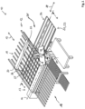
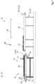
- a panel dividing system has the overall reference number 10. It includes a feed table 12 formed from several roller rails, a dividing device 13, in the present case designed as a saw, with a dividing line 14 ("saw line"), and a removal table 16.
- the removal table 16 can consist of several roller rails or as a segmented air cushion table be educated. Alternatively, the removal table 16 can have other transport elements, for example driven or non-driven belts or rollers.
- the division line 14 is in Figure 1 not immediately recognizable and therefore only indicated as a dash-dotted line.
- the plate dividing system 10 also includes a first conveyor device 18, which in the present case comprises a portal-like program slide 20 which is movably held on side rails (without reference numbers) and to which a plurality of collets 22 are attached. For reasons of clarity, only one collet chuck 22 is provided with a reference number.
- a workpiece lying on the feed table 12 can be moved in the direction of the dividing line 14 along a first conveying direction 19 indicated by a double arrow.
- the plate dividing system 10 further comprises a handling device 23, in the present case a robot 24.
- This comprises a base 26 and a robot arm 28 which is articulated to the base 26 and can be rotated about a vertical axis 27 relative to the base 26.
- the robot arm 28 in turn comprises two relative to one another a horizontal axis (without reference numerals) pivotable sections and a plate-shaped suction gripping device 30 attached to the projecting end of the robot arm and arranged in a substantially horizontal plane.
- the suction gripping device 30 is also relative to the robot arm 28 about a vertical axis (without reference numerals) rotatably mounted.
- the robot 24 shown in the present embodiment is a multi-axis robot with a relatively simple design. In principle, it is of course also conceivable to use another robot that has several movement and pivot axes. However, fully automatic operation of the panel dividing system 10 can also be achieved with the robot 24 shown here.
- the suction gripping device 30 is designed as a plate-shaped truss construction and has a large number of individual pneumatic suction cups 29 on its underside. This can be used to create workpieces Different sizes, for example workpieces that are smaller than the total extent of the suction gripping device 30, can be gripped without any problems.
- the plate dividing system 10 also has a buffer device 31 with a buffer table 32.
- the buffer table 32 is arranged laterally from the feed table 12 as seen in the first conveying direction 19 and can also be referred to as the first segment 33 of the buffer device 31.
- a buffered workpiece can be moved in a second conveying direction 38.
- the second conveying direction 38 is oriented transversely to the first conveying direction 19, in the present case orthogonally. In embodiments not shown, a different angle between the two conveying directions 19, 38 is also conceivable.
- the buffer device 31 extends into the feed table 12 and has a second segment 35.
- the second segment 35 is arranged in the feed table 12.
- the robot 24 has a working area or storage area which is circular in the top view and in the plane of the feed table 12, removal table 16 and buffer device 31, the center of which forms the axis 27.
- This working area overlaps with the buffer device 31, in particular with the first segment 33 of the buffer device 31, and there in turn with an area 37 adjacent to the feed table 12.
- a divided workpiece can thus be picked up after a dividing process, if necessary rotated and placed on the buffer device 31. in particular on the first segment 33 of the buffer device 31.
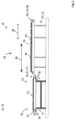
- Figure 2 shows a schematic and partially sectioned view of the panel dividing system 10 along section AA in Figure 1 , i.e. the area of the buffer device 31 and the feed table 12.
- a first further conveyor device 34 is assigned to the first segment 33 and a second further conveyor device 36 is assigned to the second segment 35.
- the first further conveyor device 34 and the second further conveyor device 36 each have a plurality of parallel rotating conveyor elements 40, 42 in the form of belt conveyors 44, 46.
- other conveying elements for example in the form of a chain or in the form of rollers with a slide for moving the workpieces, are also conceivable.
- a top side 50 of the first segment 33 or the first further conveyor device 34 is elevated compared to a top side 52 of the feed table 12.
- the increase can be between 10 and 30 millimeters, for example 20 millimeters. Other distances are also conceivable.
- the second segment 35 or the second conveyor device 36 is designed to be height-adjustable relative to the feed table 12.
- the second segment 35 or the second further conveyor device 36 can be moved between a first position, in which an upper side 54 of the second segment 35 or the second further conveyor device 36 is arranged below the upper side 52 of the feed table 12, and a second position, in which the top 54 of the second segment 35 is arranged above the top 52 of the feed table.
- a workpiece lying on the feed table 12 can be transported from the first conveyor device 18 along the first conveying direction 19, for example Divider 13 can be moved without this movement being hindered by the buffer device 31 and the second segment 35.
- the feed table is designed to be height-adjustable relative to the second segment of the buffer device.
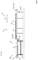
- FIG 3 an operating situation is shown in which the second segment 35 or the second further conveyor device 36 is in the second position, in which the top 54 of the second segment 35 is arranged above the top 52 of the feed table.
- a workpiece 48 can be transferred from the first segment 33 to the second segment 35.
- the first further conveyor device 34 with the belt conveyor 46 is first activated, so that the workpiece 48 is moved in the second conveying direction 38 towards the feed table 12.
- this is also activated.
- a vertically displaceable stop 56 for aligning the workpiece 48 is arranged on the feed table 12. If the singular is used here and below for the stop 56, this does not mean that it necessarily has to be a single element.
- the purpose of the stop 56 is to define a stop line orthogonal to the dividing line 14, as will be explained in more detail below. For this purpose, several individual stops can be provided, which are arranged in a straight line orthogonal to the dividing line 14, or an elongated straight "angle ruler" orthogonal to the dividing line 14 can be provided.
- the second segment 35 has a driver element 58, which is connected to the second further conveyor device 36 or to the rotating one Conveying element 40 (belt conveyor 44) is coupled and with which the workpiece 48 can be moved to the stop 56.
- the singular used does not mean that only a single driver element 58 is necessarily provided.
- the purpose of the driver element 58 is to move a workpiece lying on the feed table 12 translationally and transversely to the first conveying direction 19.
- several driver elements 58 should generally be used, for example one driver element 58 on each of the parallel belt conveyors 44, in order to avoid twisting of the workpiece 48 during movement.
- the driver element 58 is attached to the rotating conveyor element 40 or the belt conveyor 44, so that it cannot carry out a completely rotating movement.
- a driver element that can be coupled to the rotating conveyor element 40 in the form of the belt conveyor 44 is also conceivable.
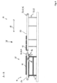
- the second additional conveyor device 36 of the second segment 35 is also deactivated.
- the second segment 35 or the second further conveyor device 36 is lowered, for example by means of a pneumatic or electric actuator, so that the workpiece 48 comes to rest on the top 52 of the feed table 12.
- the displaceable stop 56 is again shifted upwards, for example by means of a pneumatic or electrical actuator, into a position in which it is arranged at least in some areas above the top 52 of the feed table 12.
- the second conveyor 36 is further moved so that the driver element 58 in Figure 6 is in the extreme left position, and then the driver element 58 is moved upwardly into its extended position in which it protrudes with its contact portion 60 above the top 52 of the feed table 12.
- the second further conveyor device 36 of the second segment 35 which is no longer in contact with the workpiece 48 lying on the feed table 12 due to the lowering, is then driven, so that the driver element 58 moves to the side of the second segment 35 or .of the feed table 12, in Figure 6 i.e. moved all the way to the left.
- the driver element 58 is then shifted upwards in such a way that a contact section 60 is moved from a first position below the top 52 of the feed table 12 to a second position in which the contact section 60 is arranged at least partially above the top 52 of the feed table 12.
- the driver element 58 has an actuator in the form of a pneumatic cylinder (not shown). In embodiments not shown, actuators in the form of a hydraulic cylinder or an electric servomotor are also conceivable.
- the stop 56 and the alignment process just described define a position of the workpiece 48 that is orthogonal to the saw line 14.
- the workpiece 48 is thus aligned relative to the saw line 14.
- the workpiece 48 thus maintains its fixed position aligned with the saw line 14.
- Now at least the driver 58 is connected to the contact section 60 and possibly also the stop 56 again lowered.
- the stop 56 and the driver element 58 are, as indicated above, moved into a position below the top 52 of the feed table 12 and thus moved away from the workpiece 48.
- the second further conveyor device 36 in the form of the belt conveyor 44 is moved in such a way that the driver element 58, the contact section 60 of which is (still) below the top 52 of the feed table 12 is located, on the side of the feed table 12 facing away from the stop 56 (i.e. in the Figures 2 and the extreme left position shown). In this way, when the further workpiece 49 is transferred to the second segment 35, the maximum conveying path of the second belt conveyor 46 is available.
- workpieces 48, 49 can be temporarily stored ("buffered"), so that other workpieces lie on the feed table 12 and can be fed to the dividing device 13.
- the first belt conveyor 46 of the first segment 34 it is also possible for the first belt conveyor 46 of the first segment 34 to also move a workpiece lying on it away from the feed table 12, so that the robot 24 can move a divided workpiece between the feed table 12 and a workpiece already lying in the buffer device 31 can place the workpiece.
- a plate dividing system 10 for dividing plate-shaped workpieces 48, 49 is provided with a feed table 12, a conveyor device 18 for transporting an initial workpiece on the feed table 12 in a first conveying direction 19, one arranged after the feed table 12 as seen in the first conveying direction 19
- the plate dividing system 10 is characterized in that the buffer device 31 has at least one further conveyor device 34, 36, preferably two conveyor devices 34, 36, for moving the buffered workpiece 48 in the second conveying direction 38.
- the plate dividing system 10 is characterized in that the buffer device 31 has a first segment 33, which is arranged laterally from the feed table 12, and a separate second segment 35, which is arranged in the area of the feed table 12, wherein the first segment 33 is assigned a first of the further conveying devices 34 and the second segment 35 is assigned a second of the further conveying devices 36.
- the plate dividing system 10 is characterized in that an upper side 50 of the first segment 33 or the first further conveyor device 34 is at least temporarily elevated relative to an upper side 52 of the feed table 12.
- the plate dividing system 10 according to one of the two previous aspects is characterized in that the second segment 35 or the second further conveyor device 36 is designed to be height-adjustable relative to the feed table 12 or the feed table is designed to be height-adjustable relative to the second segment.
- the plate dividing system 10 is characterized in that the first further conveyor device 34 and/or the second further conveyor device 36 each have/have a rotating conveyor element 40, 42.
- the plate dividing system 10 is characterized in that a displaceable stop 56 for aligning the buffered workpiece 48 is arranged on the feed table 12.
- the plate dividing system 10 according to one of the previous five aspects is characterized in that the second segment 35 has a driver element 58 coupled to the second further conveyor device 36, in particular to its conveyor element 40, 44, with which the divided workpiece 48 is aligned can be moved to the stop 56.
- the plate dividing system 10 is characterized in that the driver element 58 has a contact section 60 which is displaceable in such a way that it is in a first position below a top side 52 of the feed table 12 and in a second position at least partially above the Top 52 of the feed table 12 is arranged.
- the method according to the previous aspect is characterized in that the divided workpiece 48, 49 is transferred from a first segment 33 of the buffer device 31, which is arranged laterally to the feed table 12 and buffers the divided workpiece 48, 49, to a separate second segment 35 is transferred to the buffer device 31, which is arranged in the area of the feed table 12.
- the method according to the previous aspect is characterized in that the second segment 35 is raised relative to the feed table 12 at least approximately to the level of the first segment 33 before or during the transfer of the divided workpiece 48, 49 or that the feed table before or is lowered relative to the second segment during the transfer of the divided workpiece.
- the method according to one of the previous two aspects is characterized in that the divided workpiece 48, 49 is moved on the first segment 33 by means of a first further conveyor device 34 and is moved on the second segment 35 by means of a second further conveyor device 36, preferably the second further conveyor device 36 is activated as soon as a section of the divided workpiece 48, 49 reaches the second segment 35.
- the method according to one of the previous three aspects is characterized in that the divided workpiece 48, 49 is placed on the feed table 12 by lowering the second segment 35.
- the method according to one of the previous four aspects is characterized in that the divided workpiece 48, 49 placed on the feed table 12 is aligned relative to the feed table 12 and/or to the dividing device 13, by means of a driver element 58 arranged at least in some areas above a top side 52 of the feed table 12, it is moved to a displaceable stop 56 of the feed table 12 and is pressed against it.
- the method according to the previous aspect is characterized in that the divided workpiece 48, 49 is fixed in the aligned state and placed on the feed table by at least one clamping element 22, and that the driver element 58 and the stop 56 are then secured from the divided workpiece 48 , 49 to be relocated away.
Abstract
Eine Plattenaufteilanlage zum Aufteilen von plattenförmigen Werkstücken (48,49), umfasst einen Zuführtisch (12), eine Fördereinrichtung (18) zum Transportieren eines Ausgangswerkstücks auf dem Zuführtisch (12) in einer ersten Förderrichtung (19), eine in der ersten Förderrichtung (19) gesehen nach dem Zuführtisch (12) angeordnete Aufteileinrichtung (13) zum Aufteilen des Ausgangswerkstücks in ein aufgeteiltes Werkstück (48,49) mit einer quer zur ersten Förderrichtung 19) angeordneten Aufteillinie (14), und eine Puffereinrichtung (31) zum Puffern des aufgeteilten Werkstücks (48,49) vor einem weiteren Aufteilvorgang, wobei die Puffereinrichtung (31) derart ausgebildet ist, dass in dieser das gepufferte Werkstück (48,49) in einer zweiten Förderrichtung (38) bewegt werden kann.A plate dividing system for dividing plate-shaped workpieces (48, 49), comprises a feed table (12), a conveyor device (18) for transporting an initial workpiece on the feed table (12) in a first conveying direction (19), one in the first conveying direction (19 ) seen after the feed table (12) arranged dividing device (13) for dividing the initial workpiece into a divided workpiece (48, 49) with a dividing line (14) arranged transversely to the first conveying direction 19), and a buffer device (31) for buffering the divided Workpiece (48,49) before a further dividing process, wherein the buffer device (31) is designed such that the buffered workpiece (48,49) can be moved in a second conveying direction (38).
Description
Die vorliegende Erfindung betrifft eine Plattenaufteilanlage zum Aufteilen von plattenförmigen Werkstücken nach dem Oberbegriff des Anspruchs 1, sowie ein Verfahren zum Betreiben einer solchen Plattenaufteilanlage nach dem Oberbegriff des nebengeordneten Anspruchs.The present invention relates to a panel dividing system for dividing plate-shaped workpieces according to the preamble of claim 1, and a method for operating such a panel dividing system according to the preamble of the independent claim.
Derartige Plattenaufteilanlagen sind sowohl vom Markt her als auch aus der
Die
Der vorliegenden Erfindung liegt daher die Aufgabe zugrunde, mit einfachen konstruktiven Mitteln einen vollautomatischen Einsatz einer Plattenaufteilanlage zu ermöglichen.The present invention is therefore based on the object of enabling a fully automatic use of a panel dividing system with simple structural means.
Diese Aufgabe wird durch eine Plattenaufteilanlage mit den Merkmalen des Anspruchs 1 sowie durch ein Verfahren mit den Merkmalen des nebengeordneten Anspruchs gelöst.This object is achieved by a panel dividing system with the features of claim 1 and by a method with the features of the independent claim.
Die erfindungsgemäße Plattenaufteilanlage hat den Vorteil, dass sie vollautomatisch arbeiten kann, wodurch zunächst eine sehr hohe Wirtschaftlichkeit erreicht werden kann. Dabei ist die Plattenaufteilanlage preiswert und mit einfachen konstruktiven Mitteln aufgebaut. So kann mittels einer Fördereinrichtung ein Werkstück zu einer Aufteileinrichtung transportiert und dort in ein aufgeteiltes Werkstück zerkleinert werden. In einer Puffereinrichtung kann das aufgeteilte Werkstück vor einem weiteren Aufteilvorgang gepuffert werden.The panel dividing system according to the invention has the advantage that it can work fully automatically, which means that a very high level of economic efficiency can be achieved. The panel dividing system is inexpensive and constructed using simple structural means. A workpiece can be transported to a dividing device by means of a conveyor and can be comminuted there into a divided workpiece. The divided workpiece can be buffered in a buffer device before a further division process.
Erfindungsgemäß ist die Puffereinrichtung derart ausgebildet, dass in dieser das gepufferte Werkstück in einer zweiten Förderrichtung bewegt werden kann, wobei die zweite Förderrichtung quer zur ersten Förderrichtung orientiert ist. Insoweit handelt es sich bei der Puffereinrichtung nicht um eine bloße Ablagemöglichkeit, sondern um eine aktive Einrichtung, die das gepufferte Werkstück gezielt bewegen kann. So kann die Puffereinrichtung das Werkstück in der zweiten Förderrichtung zum Zuführtisch hin oder auch vom Zuführtisch weg bewegen.According to the invention, the buffer device is designed such that the buffered workpiece can be moved in a second conveying direction, the second conveying direction being oriented transversely to the first conveying direction. In this respect, the buffer device is not just a storage option, but rather an active device that can move the buffered workpiece in a targeted manner. The buffer device can thus move the workpiece in the second conveying direction towards the feed table or away from the feed table.
Dies ermöglicht die Verwendung einer konstruktiv einfachen und kompakten Handhabungseinheit, beispielsweise eines Roboters, deren Arbeitsbereich nur einen Abschnitt der Puffereinrichtung überdecken muss. Insoweit sind die Größe und die Speicherkapazität der Puffereinrichtung praktisch unabhängig von der eingesetzten Handhabungseinheit. So kann trotz kompakter, hinsichtlich ihres Arbeitsbereichs begrenzter Handhabungseinheit dennoch eine große Puffereinrichtung realisiert werden. Außerdem ermöglicht die quer ausgerichtete Förderrichtung eine seitliche Anordnung der Puffereinrichtung, wodurch die Längserstreckung der Plattenaufteilanlage klein gehalten wird.This enables the use of a structurally simple and compact handling unit, for example a robot, whose work area only has to cover a section of the buffer device. In this respect, the size and storage capacity of the buffer device are practically independent of the handling unit used. Despite a compact handling unit with a limited working area, a large buffer device can still be implemented. In addition, the transversely oriented conveying direction enables the buffer device to be arranged laterally, whereby the longitudinal extent of the panel dividing system is kept small.
Der Ausdruck "quer zur ersten Förderrichtung" ist im weitesten Sinne zu verstehen. So kann die zweite Förderrichtung schräg, d.h. unter einem vom Orthogonalen abweichenden Winkel, oder orthogonal zur ersten Förderrichtung orientiert sein.The expression “across the first conveying direction” is to be understood in the broadest sense. The second conveying direction can thus be oriented obliquely, i.e. at an angle that deviates from the orthogonal, or orthogonally to the first conveying direction.
Im Konkreten kann die Puffereinrichtung mindestens eine weitere Fördereinrichtung zum Bewegen des gepufferten Werkstücks in der zweiten Förderrichtung aufweisen. Damit lässt sich das gepufferte Werkstück ganz gezielt und weitgehend unabhängig von anderen Fördereinrichtungen bewegen, und zwar entlang der zweiten Fördereinrichtung. Vorzugsweise kann die Puffereinrichtung zwei Fördereinrichtungen zum Bewegen des gepufferten Werkstücks aufweisen. Hiermit können konstruktiv kleinere Fördereinrichtungen eingesetzt werden, wobei zum Transport des gepufferten Werkstücks nur die Fördereinrichtung angetrieben werden muss, auf der sich das Werkstück befindet. Sind mehrere Werkstücke in der Puffereinrichtung gepuffert, kann durch die separaten Fördereinrichtungen eine gleichzeitige aber unterschiedliche Handhabung der Werkstücke erfolgen.Specifically, the buffer device can have at least one further conveyor device for moving the buffered workpiece in the second conveying direction. This allows the buffered workpiece to be moved in a very targeted manner and largely independently of other conveying devices, namely along the second conveying device. Preferably, the buffer device can have two conveyor devices for moving the buffered workpiece. This means that smaller conveyor devices can be used, whereby only the conveyor on which the workpiece is located has to be driven to transport the buffered workpiece. If several workpieces are buffered in the buffer device, the separate conveyor devices can be used to handle the workpieces simultaneously but differently.
In vorteilhafter Weise kann die Puffereinrichtung ein erstes Segment, welches seitlich vom Zuführtisch angeordnet ist, und ein separates zweites Segment, welches im Bereich des Zuführtisches angeordnet ist, aufweisen, wobei dem ersten Segment eine erste der weiteren Fördereinrichtungen und dem zweiten Segment eine zweite der weiteren Fördereinrichtungen zugeordnet ist. Somit können durch das erste Segment und der ersten weiteren Fördereinrichtung eine Pufferung sowie eine Verlagerung von Werkstücken in der zweiten Förderrichtung erfolgen. Somit lässt sich je nach Bedarf Pufferraum in einem Abschnitt des ersten Segments freigeben, beispielsweise in einem an den Zuführtisch angrenzenden Bereich des ersten Segments, oder ein Werkstück lässt sich gezielt an den Zuführtisch heranführen. Durch eine Bewegung der ersten Fördereinrichtung, die ein gepuffertes Werkstück in der zweiten Förderrichtung vom Zuführtisch weg bewegt, wird die Kapazität des Puffers, d.h. die Anzahl der Ablageplätze für Werkstücke, vergrößert, und es kann die Reihenfolge der Werkstücke in Richtung zum Zuführtisch hin verändert werden. Mittels des separaten zweiten Segments und dessen Fördereinrichtung kann eine kontrollierteAdvantageously, the buffer device can have a first segment, which is arranged laterally from the feed table, and a separate second segment, which is arranged in the area of the feed table, the first segment having a first of the further conveying devices and the second segment having a second of the further ones Funding facilities are assigned. The first segment and the first additional conveyor device can therefore be used to buffer and shift workpieces in the second conveying direction. Buffer space can thus be released in a section of the first segment as required, for example in an area of the first segment adjacent to the feed table, or a workpiece can be brought specifically to the feed table. By moving the first conveyor device, which moves a buffered workpiece away from the feed table in the second conveying direction, the capacity of the buffer, ie the number of storage spaces for workpieces, is increased, and the order of the workpieces can be changed in the direction of the feed table . By means of the separate second segment and its conveying device, a controlled
Übergabe des gepufferten Werkstücks auf den Zuführtisch und ggf. eine Positionierung des Werkstücks erfolgen. Das erste Segment kann auch als "aktiver Werkstückpuffer" oder "aktiver Streifenpuffer" bezeichnet werden. Das zweite Segment kann auch als "Querübergabe" bezeichnet werden.The buffered workpiece is transferred to the feed table and, if necessary, the workpiece is positioned. The first segment can also be referred to as the “active workpiece buffer” or “active strip buffer”. The second segment can also be referred to as “lateral handover”.
Vorteilhafterweise kann die Plattenaufteilanlage eine Handhabungseinrichtung zur Handhabung von ggf. aufgeteilten Werkstücken aufweisen, beispielsweise einen Roboter mit einer Saug-Greifeinrichtung. Diese kann an einem abragenden Ende eines Roboterarms des Roboters angeordnet sein und zum Aufnehmen oder Greifen von Werkstücken dienen. Mittels der Handhabungseinrichtung bzw. des Roboters lässt sich ein aufgeteiltes Werkstück nach einem Aufteilvorgang aufnehmen und auf der Puffereinrichtung ablegen. Dabei kann das aufgeteilte Werkstück ggf. gedreht werden. In diesem Zusammenhang ist es von Vorteil, wenn sich der Arbeitsbereich oder Ablegebereich der Handhabungseinrichtung bzw. des Roboters und die Puffereinrichtung, insbesondere das erste Segment der Puffereinrichtung, zumindest teilweise überschneiden. Insbesondere liegt ein zum Zuführtisch benachbarter Bereich des ersten Segments der Puffereinrichtung im Arbeitsbereich der Handhabungseinrichtung, ein vom Zuführtisch entfernter Bereich des ersten Segments dagegen nicht.Advantageously, the panel dividing system can have a handling device for handling possibly divided workpieces, for example a robot with a suction gripping device. This can be arranged on a projecting end of a robot arm of the robot and can be used to pick up or grip workpieces. Using the handling device or the robot, a divided workpiece can be picked up after a dividing process and placed on the buffer device. The divided workpiece can be rotated if necessary. In this context, it is advantageous if the working area or storage area of the handling device or the robot and the buffer device, in particular the first segment of the buffer device, at least partially overlap. In particular, an area of the first segment of the buffer device that is adjacent to the feed table is in the working area of the handling device, whereas an area of the first segment that is remote from the feed table is not.
Zweckmäßigerweise kann eine Oberseite des ersten Segments bzw. der ersten weiteren Fördereinrichtung relativ zu einer Oberseite des Zuführtisches zumindest zeitweise erhöht sein. Dies erleichtert die Übergabe vom ersten Segment auf den Zuführtisch. Dabei ist denkbar, dass die Oberseite der ersten weiteren Fördereinrichtung bzw. des ersten Segments um 5 bis 35 Millimeter, weiter vorzugsweise um 10 bis 30 Millimeter, weiter vorzugsweise um 15 bis 25 Millimeter, weiter vorzugsweise um 20 Millimeter erhöht ist.An upper side of the first segment or the first further conveyor device can expediently be elevated at least temporarily relative to an upper side of the feed table. This makes the transfer from the first segment to the feed table easier. It is conceivable that the top of the first further conveyor device or the first segment is increased by 5 to 35 millimeters, more preferably by 10 to 30 millimeters, more preferably by 15 to 25 millimeters, more preferably by 20 millimeters.
Das zweite Segment bzw. die zweite der weiteren Fördereinrichtungen kann relativ zum Zuführtisch höhenverstellbar ausgebildet sein, oder es kann der Zuführtisch relativ zum zweiten Segment höhenverstellbar sein. Mit anderen Worten kann das zweite Segment bzw. die zweite weitere Fördereinrichtung zwischen einer ersten Stellung, in der eine Oberseite des zweiten Segments bzw. der zweiten weiteren Fördereinrichtung unterhalb einer Oberseite des Zuführtischs angeordnet ist, und einer zweiten Stellung, bei der die Oberseite des zweiten Segments oder der zweiten weiteren Fördereinrichtung oberhalb der Oberseite des Zuführtischs (und vorzugsweise auf gleicher Höhe wie das erste Segment) angeordnet ist, verstellt werden. Dies gilt auch für den kinematisch umgekehrten Fall, in dem der Zuführtisch relativ zum zweiten Segment höhenverstellbar ist. Damit kann das zweite Segment bzw. die zweite weitere Fördereinrichtung ganz gezielt dann aktiviert werden, wenn eine Übergabe eines gepufferten Werkstücks vom ersten Segment auf das zweite Segment erfolgt. Damit lässt sich eine Übergabe erleichtern. Findet keine Übergabe statt, kann das zweite Segment bzw. die zweite weitere Fördereinrichtung in ihrer ersten, vertieften Position verbleiben (oder es kann der Zuführtisch in seiner erhöhten Position verbleiben), so dass ein ungestörtes Zuführen von Werkstücken in der ersten Förderrichtung durch die erste Fördereinrichtung erfolgen kann.The second segment or the second of the further conveying devices can be designed to be height-adjustable relative to the feed table, or the feed table can be height-adjustable relative to the second segment. In other words, the second segment or the second further conveyor device can move between a first position in which an upper side of the second segment or the second further conveying device is arranged below a top side of the feed table, and a second position in which the top of the second segment or the second further conveying device is arranged above the top of the feed table (and preferably at the same height as the first segment). . This also applies to the kinematically opposite case, in which the feed table is height-adjustable relative to the second segment. This means that the second segment or the second further conveyor device can be activated in a very targeted manner when a buffered workpiece is transferred from the first segment to the second segment. This makes handover easier. If no transfer takes place, the second segment or the second additional conveyor device can remain in its first, recessed position (or the feed table can remain in its elevated position), so that workpieces can be fed undisturbed in the first conveying direction by the first conveyor device can be done.
Die erste weitere Fördereinrichtung und/oder die zweite weitere Fördereinrichtung können jeweils ein umlaufendes Förderelement aufweisen. Somit ist ein schonender Transport der Werkstücke ermöglicht, da zwischen Werkstück und Förderelement keine Relativbewegung in Kontaktebene stattfindet. Beim umlaufenden Förderelement kann es sich um einen Riemen oder um eine Kette handeln. Alternativ hierzu können auch Rollenschienen als Förderelement eingesetzt werden, wobei ein Schieber die Werkstücke antreiben kann, oder wobei die Rollen selbst angetrieben sind. Die Rollen der Rollenschienen können eine elastische Oberfläche, beispielsweise in Form einer Gummierung, aufweisen.The first further conveyor device and/or the second further conveyor device can each have a rotating conveyor element. This enables gentle transport of the workpieces, since there is no relative movement in the contact plane between the workpiece and the conveying element. The rotating conveyor element can be a belt or a chain. Alternatively, roller rails can also be used as a conveying element, whereby a slider can drive the workpieces, or where the rollers themselves are driven. The rollers of the roller rails can have an elastic surface, for example in the form of a rubber coating.
In vorteilhafter Weise kann am Zuführtisch ein verlagerbarer Anschlag zur Ausrichtung des zunächst gepufferten und dann von der Puffereinrichtung auf den Zuführtisch geförderten Werkstücks angeordnet sein. Somit lässt sich ein definierter Anschlag für ein Werkstück realisieren, ohne jedoch die Handhabung und den Transport der Werkstücke durch einen feststehenden Anschlag zu beeinträchtigen. Dabei ist von Vorteil, wenn der Anschlag zwischen einer ersten Position, in der sich der Anschlag unterhalb einer Oberseite des Zuführtisches befindet, und zwischen einer zweiten Position, in der der Anschlag mindestens bereichsweise oberhalb der Oberseite des Zuführtisches angeordnet ist, verlagert werden kann. Die Verlagerung des Anschlags kann auf verschiedene Weise erfolgen, beispielsweise kann der Anschlag verschwenkbar, ausfahrbar oder teleskopierbar ausgebildet sein. Dabei ist nicht erforderlich, dass durch den Anschlag eine einzelne durchgehende Anschlagsfläche gebildet wird. Vielmehr ist es zur Funktion des Anschlages auch ausreichend, dass mehrere Anschlagsabschnitte, beispielsweise in Form von Pins, relativ zur Oberfläche des Zuführtisches verlagert werden.Advantageously, a displaceable stop can be arranged on the feed table for aligning the workpiece that is initially buffered and then conveyed to the feed table by the buffer device. This makes it possible to create a defined stop for a workpiece without impairing the handling and transport of the workpieces due to a fixed stop. It is advantageous if the stop is displaced between a first position, in which the stop is located below an upper side of the feed table, and between a second position, in which the stop is arranged at least partially above the upper side of the feed table can be. The stop can be displaced in various ways, for example the stop can be designed to be pivotable, extendable or telescopic. It is not necessary for the stop to form a single, continuous stop surface. Rather, for the stop to function, it is also sufficient that several stop sections, for example in the form of pins, are displaced relative to the surface of the feed table.
In vorteilhafter Weise kann das zweite Segment ein mit der zweiten weiteren Fördereinrichtung gekoppeltes Mitnehmerelement aufweisen, mit dem das aufgeteilte Werkstück zum Ausrichten an den Anschlag bewegt werden kann. Dabei kann das Mitnehmerelement mit dem Förderelement der zweiten weiteren Fördereinrichtung gekoppelt sein. Dies hat den Vorteil, dass mit einer Einrichtung, nämlich der zweiten weiteren Fördereinrichtung, einerseits ein Transportieren eines Werkstücks und andererseits ein Positionieren des Werkstücks erfolgen kann. Zum Transportieren des Werkstücks befindet sich die zweite weitere Fördereinrichtung oberhalb einer Oberseite eines Zuführtisches und zum Positionieren des Werkstückes unterhalb einer Oberseite des Zuführtisches, wobei das Werkstück mittels des Mitnehmerelements auf dem Zuführtisch bewegt werden kann.Advantageously, the second segment can have a driver element coupled to the second further conveyor device, with which the divided workpiece can be moved to align it with the stop. The driver element can be coupled to the conveying element of the second further conveying device. This has the advantage that with one device, namely the second further conveyor device, a workpiece can be transported on the one hand and the workpiece can be positioned on the other hand. To transport the workpiece, the second further conveyor device is located above a top side of a feed table and to position the workpiece below a top side of the feed table, whereby the workpiece can be moved on the feed table by means of the driver element.
In vorteilhafter Weise kann das Mitnehmerelement einen Kontaktabschnitt aufweisen, der derart verlagerbar ist, dass dieser in einer ersten Stellung unterhalb einer Oberseite eines Zuführtisches und in einer zweiten Stellung mindestens bereichsweise oberhalb der Oberseite des Zuführtisches angeordnet ist. Somit kann eine gezielte Handhabung des Werkstücks erfolgen. Dabei ist denkbar, dass das Mitnehmerelement einen Aktor aufweist, der bei Ansteuerung den Kontaktabschnitt derart verlagert, dass dieser zumindest bereichsweise oberhalb der Oberseite des Zuführtisches angeordnet ist. Hinsichtlich des Aktors ist denkbar, dass dieser als Pneumatikzylinder oder Hydraulikzylinder ausgebildet ist.Advantageously, the driver element can have a contact section which is displaceable in such a way that it is arranged in a first position below a top side of a feed table and in a second position at least partially above the top side of the feed table. This allows targeted handling of the workpiece. It is conceivable that the driver element has an actuator which, when activated, displaces the contact section in such a way that it is arranged at least in some areas above the top of the feed table. With regard to the actuator, it is conceivable that it is designed as a pneumatic cylinder or hydraulic cylinder.
Die eingangs genannte Aufgabe wird auch durch ein Verfahren zum Betreiben einer Plattenaufteilanlage gelöst, das die folgenden Schritte umfasst:
- Bereitstellen eines Ausgangswerkstücks an einem Zuführtisch,
- Transportieren des Ausgangswerkstücks auf dem Zuführtisch mittels einer Fördereinrichtung in einer ersten Förderrichtung zu einer Aufteileinrichtung,
- Aufteilen des Ausgangswerkstücks in mindestens ein aufgeteiltes Werkstück mittels der Aufteileinrichtung und
- Puffern des aufgeteilten Werkstücks in einer Puffereinrichtung vor einem weiteren Aufteilvorgang,
- Providing an initial workpiece at a feed table,
- Transporting the initial workpiece on the feed table by means of a conveyor device in a first conveying direction to a dividing device,
- Dividing the initial workpiece into at least one divided workpiece using the dividing device and
- Buffering the divided workpiece in a buffer device before a further division process,
Zweckmäßigerweise kann das aufgeteilte Werkstück mittels einer Handhabungseinrichtung gehandhabt werden, beispielsweise mittels eines Roboters mit einer Saug-Greifeinrichtung. Diese kann an einem abragenden Ende eines Roboterarms des Roboters angeordnet sein. Mittels der Handhabungseinrichtung bzw. des Roboters kann ein aufgeteiltes Werkstück nach einem Aufteilvorgang aufgenommen und auf der Puffereinrichtung abgelegt werden. Dabei kann das aufgeteilte Werkstück gedreht werden. In diesem Zusammenhang ist es von Vorteil, wenn sich der Arbeitsbereich oder Ablegebereich der Handhabungseinrichtung bzw. des Roboters und die Puffereinrichtung, insbesondere das erste Segment der Puffereinrichtung, zumindest teilweise überschneiden. Insbesondere liegt ein zum Zuführtisch benachbarter Bereich des ersten Segments der Puffereinrichtung im Arbeitsbereich der Handhabungseinrichtung, ein vom Zuführtisch entfernter Bereich des ersten Segments dagegen nicht.The divided workpiece can expediently be handled by means of a handling device, for example by means of a robot with a suction gripping device. This can be arranged on a projecting end of a robot arm of the robot. Using the handling device or the robot, a divided workpiece can be picked up after a division process and placed on the buffer device. The divided workpiece can be rotated. In this context, it is advantageous if the working area or storage area of the handling device or the robot and the buffer device, in particular the first segment of the buffer device, at least partially overlap. In particular, an area of the first segment of the buffer device that is adjacent to the feed table is in the working area of the handling device, whereas an area of the first segment that is remote from the feed table is not.
In vorteilhafter Weise kann das aufgeteilte Werkstück von einem ersten Segment der Puffereinrichtung, das seitlich zum Zuführtisch angeordnet ist und das aufgeteilte Werkstück puffert, auf ein separates zweites Segment der Puffereinrichtung übergeben werden, das im Bereich des Zuführtisches angeordnet ist. Somit kann die eigentliche Pufferung von Werkstücken in einem ersten Segment der Puffereinrichtung außerhalb des Zuführtisches erfolgen. Das erste Segment kann auch als "aktiver Werkstückpuffer" oder "aktiver Streifenpuffer" bezeichnet werden. Die Übergabe und ggf. Positionierung des zweiten Werkstücks auf den Zuführtisch kann mit Hilfe des zweiten Segments erfolgen, das im Bereich des Zuführtisches angeordnet ist. Das zweite Segment kann auch als "Querübergabe" bezeichnet werden.Advantageously, the divided workpiece can be transferred from a first segment of the buffer device, which is arranged laterally to the feed table and buffers the divided workpiece, to a separate second segment of the buffer device, which is arranged in the area of the feed table. The actual buffering of workpieces can therefore take place in a first segment of the buffer device outside the feed table. The first segment can also be referred to as the “active workpiece buffer” or “active strip buffer”. The transfer and, if necessary, positioning of the second workpiece onto the feed table can be done with the help of the second segment, which is arranged in the area of the feed table. The second segment can also be referred to as “lateral handover”.
Zweckmäßigerweise kann das zweite Segment vor oder während der Übergabe des aufgeteilten Werkstücks relativ zum Zuführtisch mindestens auf die Höhe des ersten Segments angehoben und so in seiner Höhe an das erste Segment angepasst werden. Somit kann das zweite Segment ganz gezielt angehoben werden, wenn eine Übergabe eines Werkstücks vom ersten Segment auf das zweite Segment erfolgt. Findet keine solche Übergabe statt, kann das zweite Segment in einer abgesenkten Position verbleiben, in der eine Oberseite des zweiten Segments unterhalb einer Oberseite des Zuführtisches angeordnet ist. Damit kann eine ungestörte Förderung von Werkstücken in der ersten Förderrichtung des Zuführtisches erfolgen.The second segment can expediently be raised relative to the feed table to at least the height of the first segment before or during the transfer of the divided workpiece and its height can thus be adjusted to the first segment. The second segment can thus be raised in a very targeted manner when a workpiece is transferred from the first segment to the second segment. If no such transfer takes place, the second segment can remain in a lowered position in which an upper side of the second segment is arranged below an upper side of the feed table. This means that workpieces can be conveyed undisturbed in the first conveying direction of the feed table.
Gemäß einer bevorzugten Ausführungsform kann das aufgeteilte Werkstück mittels einer ersten weiteren Fördereinrichtung auf dem ersten Segment bewegt werden und mittels einer zweiten weiteren Fördereinrichtung auf dem zweiten Segment bewegt werden, wobei vorzugsweise die zweite weitere Fördereinrichtung erst dann aktiviert wird, sobald ein Abschnitt des aufgeteilten Werkstücks das zweite Segment erreicht. Damit findet eine schonende und energetisch günstige Übergabe des Werkstücks auf das zweite Segment statt. Außerdem kann so ein umlaufender Betrieb der zweiten weiteren Fördereinrichtung vermieden werden, so dass durch die zweite weitere Fördereinrichtung beispielsweise auch Positionierungsaufgaben übernommen werden können. Des Weiteren sei in diesem Zusammenhang noch erwähnt, dass durch eine Bewegung der ersten Fördereinrichtung, die ein gepuffertes Werkstück in der zweiten Förderrichtung vom Zuführtisch weg bewegt, die Kapazität des Puffers, d.h. die Anzahl der Ablageplätze für Werkstücke, vergrößert wird.According to a preferred embodiment, the divided workpiece can be moved on the first segment by means of a first further conveyor device and can be moved on the second segment by means of a second further conveyor device, wherein preferably the second further conveyor device is only activated as soon as a section of the divided workpiece second segment reached. This ensures that the workpiece is transferred to the second segment in a gentle and energy-efficient manner. In addition, rotating operation of the second further conveyor device can be avoided, so that positioning tasks can also be carried out by the second further conveyor device, for example. Furthermore, it should be mentioned in this context that By moving the first conveyor device, which moves a buffered workpiece away from the feed table in the second conveying direction, the capacity of the buffer, ie the number of storage spaces for workpieces, is increased.
Des Weiteren kann das aufgeteilte Werkstück durch Absenken des zweiten Segments auf dem Zuführtisch abgelegt werden. Somit ist ein schonendes Ablegen des Werkstücks auf dem Zuführtisch möglich.Furthermore, the divided workpiece can be placed on the feed table by lowering the second segment. This allows the workpiece to be placed gently on the feed table.
In vorteilhafter Weise kann das aufgeteilte und auf dem Zuführtisch abgelegte Werkstück zur Ausrichtung relativ zum Zuführtisch und/oder zur Aufteileinrichtung mittels eines zumindest bereichsweise oberhalb einer Oberseite des Zuführtischs angeordneten Mitnehmerelements an einen verlagerbaren Anschlag des Zuführtisches bewegt und gegen diesen gedrückt werden. Der Anschlag kann verlagerbar am Zuführtisch angeordnet sein. Die Verlagerung des Anschlags kann auf verschiedene Weise erfolgen, beispielsweise kann der Anschlag verschwenkt, ausgefahren oder teleskopiert werden. Das Mitnehmerelement kann mit der zweiten weiteren Fördereinrichtung, insbesondere mit einem umlaufenden Förderelement der zweiten weiteren Fördereinrichtung, gekoppelt sein. Damit lässt sich mit dem zweiten Segment das Werkstück transportieren und relativ zum Zuführtisch positionieren. Der apparative Aufwand ist damit deutlich reduziert.Advantageously, the divided workpiece placed on the feed table can be moved to a displaceable stop of the feed table and pressed against it for alignment relative to the feed table and / or the dividing device by means of a driver element arranged at least in some areas above an upper side of the feed table. The stop can be displaceably arranged on the feed table. The stop can be displaced in various ways, for example the stop can be pivoted, extended or telescoped. The driver element can be coupled to the second further conveyor device, in particular with a rotating conveyor element of the second further conveyor device. This means that the workpiece can be transported using the second segment and positioned relative to the feed table. The expenditure on equipment is therefore significantly reduced.
Das aufgeteilte und auf dem Zuführtisch liegende Werkstück kann im ausgerichteten Zustand zunächst durch zumindest ein Spannelement fixiert werden, und danach können das Mitnehmerelement und der Anschlag vom aufgeteilten Werkstück weg verlagert werden. Mit anderen Worten drückt das Mitnehmerelement das Werkstück gegen den Anschlag, so dass sich das Werkstück in einem gespannten Zustand befindet. In diesem gespannten Zustand fixiert ein Spannelement das Werkstück, so dass die gespannte Position beibehalten wird. Das Spannelement ist beispielsweise mittels eines Programmschiebers verbunden und kann das aufgeteilte Werkstück einem weiteren Aufteilvorgang zuführen.The divided workpiece lying on the feed table can first be fixed in the aligned state by at least one clamping element, and then the driver element and the stop can be displaced away from the divided workpiece. In other words, the driver element presses the workpiece against the stop so that the workpiece is in a clamped state. In this clamped state, a clamping element fixes the workpiece so that the clamped position is maintained. The clamping element is connected, for example, by means of a program slide and can feed the divided workpiece to a further dividing process.
Zur weiteren Ausgestaltung des Verfahrens können die im Zusammenhang mit der Plattenaufteilanlage erläuterten Maßnahmen dienen.The measures explained in connection with the panel dividing system can be used to further refine the process.
Die Erfindung wird im Folgenden anhand der Figuren näher erläutert.The invention is explained in more detail below with reference to the figures.
-
Figur 1 eine schematische, perspektivische Ansicht einer erfindungsgemäßen Plattenaufteilanlage zum Aufteilen von plattenförmigen Werkstücken mit einem Zuführtisch;Figure 1 a schematic, perspective view of a panel dividing system according to the invention for dividing panel-shaped workpieces with a feed table; -
Figur 2 eine schematische, teilweise geschnittene Darstellung entlang des Schnittes A-A inFigur 1 mit mehreren gepufferten Werkstücken;Figure 2 a schematic, partially sectioned representation along section AA inFigure 1 with several buffered workpieces; -
Figur 3 eine Darstellung entsprechendFigur 2 , wobei der Beginn einer Übergabe eines gepufferten Werkstücks an den Zuführtisch dargestellt ist;Figure 3 a representation accordinglyFigure 2 , wherein the start of a transfer of a buffered workpiece to the feed table is shown; -
Figur 4 eine Darstellung entsprechendFigur 2 , wobei das plattenförmige Werkstück vollständig an den Zuführtisch übergeben wurde;Figure 4 a representation accordinglyFigure 2 , whereby the plate-shaped workpiece has been completely transferred to the feed table; -
Figur 5 eine Darstellung entsprechendFigur 2 mit auf dem Zuführtisch abgelegtem Werkstück und einem nach oben verlagerten Anschlag;Figure 5 a representation accordinglyFigure 2 with the workpiece placed on the feed table and the stop moved upwards; -
Figur 6 in einer derFigur 2 entsprechenden Darstellung den Beginn eines Positioniervorgangs des Werkstücks undFigure 6 in one of theFigure 2 corresponding representation of the beginning of a positioning process of the workpiece and -
Figur 7 in einer derFigur 2 entsprechenden Darstellung mit gespanntem Werkstück.Figure 7 in one of theFigure 2 corresponding representation with clamped workpiece.
In allen Figuren trägt eine Plattenaufteilanlage insgesamt das Bezugszeichen 10. Sie umfasst einen aus mehreren Rollenschienen gebildeten Zuführtisch 12, eine vorliegend als Säge ausgebildete Aufteileinrichtung 13 mit einer Aufteillinie 14 ("Sägelinie"), und einen Entnahmetisch 16. Der Entnahmetisch 16 kann aus mehreren Rollenschienen oder als segmentierter Luftkissentisch gebildet sein. Alternativ kann der Entnahmetisch 16 sonstige Transportelemente aufweisen, beispielsweise angetriebene oder nicht-angetriebene Riemen oder Rollen. Die Aufteillinie 14 ist in
Zu der Plattenaufteilanlage 10 gehört ferner eine erste Fördereinrichtung 18, die vorliegend einen an seitlichen Schienen (ohne Bezugszeichen) verfahrbar gehaltenen portalartigen Programmschieber 20 umfasst, an dem eine Mehrzahl von Spannzangen 22 befestigt ist. Aus Gründen der Übersichtlichkeit ist nur eine Spannzange 22 mit einem Bezugszeichen versehen. Mittels der ersten Fördereinrichtung 18 kann ein auf dem Zuführtisch 12 liegendes Werkstück in Richtung zur Aufteillinie 14 entlang einer durch einen Doppelpfeil bezeichneten ersten Förderrichtung 19 bewegt werden.The
Die Plattenaufteilanlage 10 umfasst ferner eine Handhabungseinrichtung 23, vorliegend einen Roboter 24. Dieser umfasst eine Basis 26 und einen an der Basis 26 gelenkig befestigten, gegenüber der Basis 26 um eine vertikale Achse 27 drehbaren Roboterarm 28. Der Roboterarm 28 umfasst wiederum zwei relativ zueinander um eine horizontale Achse (ohne Bezugszeichen) schwenkbare Abschnitte und eine am abragenden Ende des Roboterarms befestigte plattenförmige und in einer im Wesentlichen horizontalen Ebene angeordnete Saug-Greifeinrichtung 30. Die Saug-Greifeinrichtung 30 ist relativ zum Roboterarm 28 ebenfalls um eine vertikale Achse (ohne Bezugszeichen) drehbar gelagert. Bei dem in der vorliegenden Ausführungsform gezeigten Roboter 24 handelt es sich um einen konstruktiv relativ einfach ausgeführten mehrachsigen Roboter. Grundsätzlich denkbar ist natürlich auch die Verwendung eines anderen Roboters, der mehrere Bewegungs- und Schwenkachsen aufweist. Jedoch lässt sich auch mit dem hier gezeigten Roboter 24 ein vollautomatischer Betrieb der Plattenaufteilanlage 10 erzielen.The
Die Saug-Greifeinrichtung 30 ist als plattenförmige Fachwerkkonstruktion ausgebildet und weist auf ihrer Unterseite eine Vielzahl von einzelnen pneumatischen Saugglocken 29 auf. Hiermit lassen sich Werkstücke unterschiedlicher Größe, beispielsweise auch Werkstücke, die kleiner sind als die Gesamterstreckung der Saug-Greifeinrichtung 30, ohne Probleme greifen.The suction gripping device 30 is designed as a plate-shaped truss construction and has a large number of individual pneumatic suction cups 29 on its underside. This can be used to create workpieces Different sizes, for example workpieces that are smaller than the total extent of the suction gripping device 30, can be gripped without any problems.
Die Plattenaufteilanlage 10 weist zudem eine Puffereinrichtung 31 mit einem Puffertisch 32 auf. Der Puffertisch 32 ist in der ersten Förderrichtung 19 gesehen seitlich vom Zuführtisch 12 angeordnet und kann auch als erstes Segment 33 der Puffereinrichtung 31 bezeichnet werden. Mittels der Puffereinrichtung 31 kann ein gepuffertes Werkstück in einer zweiten Förderrichtung 38 bewegt werden. Die zweite Förderrichtung 38 ist quer zur ersten Förderrichtung 19 orientiert, vorliegend orthogonal. Bei nicht gezeigten Ausführungsformen ist auch ein anderer Winkel zwischen den beiden Förderrichtungen 19, 38 denkbar.The
Die Puffereinrichtung 31 erstreckt sich bis in den Zuführtisch 12 hinein und weist ein zweites Segment 35 auf. Das zweite Segment 35 ist im Zuführtisch 12 angeordnet.The
Der Roboter 24 weist einen in der Draufsicht und in der Ebene von Zuführtisch 12, Entnahmetisch 16 und Puffereinrichtung 31 kreisförmigen Arbeitsbereich oder Ablegebereich auf, dessen Zentrum die Achse 27 bildet. Dieser Arbeitsbereich überschneidet sich mit der Puffereinrichtung 31, insbesondere mit dem ersten Segment 33 der Puffereinrichtung 31, und dort wiederum mit einem zum Zuführtisch 12 benachbarten Bereich 37. Somit kann ein aufgeteiltes Werkstück nach einem Aufteilvorgang aufgenommen, ggf. gedreht und auf der Puffereinrichtung 31, insbesondere auf dem ersten Segment 33 der Puffereinrichtung 31, abgelegt werden.The robot 24 has a working area or storage area which is circular in the top view and in the plane of the feed table 12, removal table 16 and
Dem ersten Segment 33 ist eine erste weitere Fördereinrichtung 34 und dem zweiten Segment 35 ist eine zweite weitere Fördereinrichtung 36 zugeordnet. Die erste weitere Fördereinrichtung 34 und die zweite weitere Fördereinrichtung 36 weisen jeweils eine Mehrzahl von parallelen umlaufenden Förderelementen 40, 42 in Form von Riemenförderern 44, 46 auf. Bei nicht gezeigten Ausführungsformen sind auch andere Förderelemente, beispielsweise in Form einer Kette oder in Form von Rollen mit einem Schieber zum Bewegen der Werkstücke denkbar.A first
Beginnend mit
Aus
Das zweite Segment 35 bzw. die zweite Fördereinrichtung 36 ist relativ zum Zuführtisch 12 höhenverstellbar ausgebildet. So kann das zweite Segment 35 bzw. die zweite weitere Fördereinrichtung 36 zwischen einer ersten Position, in der eine Oberseite 54 des zweiten Segments 35 oder der zweiten weiteren Fördereinrichtung 36 unterhalb der Oberseite 52 des Zuführtischs 12 angeordnet ist, und einer zweiten Position verfahren werden, in der die Oberseite 54 des zweiten Segments 35 oberhalb der Oberseite 52 des Zuführtischs angeordnet ist. In der in
Bei einer nicht dargestellten Ausführungsform ist anstelle des zweiten Segments bzw. der zweiten Fördereinrichtung der Zuführtisch relativ zum zweiten Segment der Puffereinrichtung höhenverstellbar ausgebildet.In an embodiment not shown, instead of the second segment or the second conveyor device, the feed table is designed to be height-adjustable relative to the second segment of the buffer device.
In
Befindet sich das Werkstück 48 mit einem Abschnitt auf dem ersten Segment 33 und mit einem anderen Abschnitt auf dem zweiten Segment 35, werden beiden weiteren Fördereinrichtungen 34, 36 angetrieben.If the
Am Zuführtisch 12 ist ein vertikal verlagerbarer Anschlag 56 zur Ausrichtung des Werkstücks 48 angeordnet. Wenn hier und nachfolgend für den Anschlag 56 der Singular verwendet wird, bedeutet dies nicht, dass es sich hierbei zwingend um ein einziges Element handeln muss. Zweck des Anschlags 56 ist es, eine zur Aufteillinie 14 orthogonale Anschlaglinie zu definieren, wie weiter unten noch stärker im Detail dargelegt werden wird. Hierzu können mehrere einzelne Anschläge vorgesehen sein, die in einer zur Aufteillinie 14 orthogonalen und geraden Linie angeordnet sind, oder es kann ein längliches und zur Aufteillinie 14 orthogonales gerades "Winkellineal" vorgesehen sein.A vertically
Außerdem weist das zweite Segment 35 ein Mitnehmerelement 58 auf, welches mit der zweiten weiteren Fördereinrichtung 36 bzw. mit dem umlaufenden Förderelement 40 (Riemenförderer 44) gekoppelt ist und mit dem das Werkstück 48 an den Anschlag 56 bewegt werden kann. Auch hier gilt, dass der verwendete Singular nicht bedeutet, dass zwingend nur ein einziges Mitnehmerelement 58 vorgesehen ist. Zweck des Mitnehmerelements 58 ist es, ein auf dem Zuführtisch 12 liegendes Werkstück translatorisch und quer zur ersten Förderrichtung 19 zu bewegen. Hierzu dürften im Allgemeinen mehrere Mitnehmerelemente 58 einzusetzen sein, beispielsweise jeweils ein Mitnehmerelement 58 an jedem der parallelen Riemenförderer 44, um ein Verdrehen des Werkstücks 48 während der Bewegung zu vermeiden.In addition, the
Das Mitnehmerelement 58 ist vorliegend am umlaufenden Förderelement 40 bzw. dem Riemenförderer 44 befestigt, so dass dieser keine vollständig umlaufende Bewegung durchführen kann. Bei nicht gezeigten Ausführungsformen ist auch ein mit dem umlaufenden Förderelement 40 in Form des Riemenförderers 44 kuppelbares Mitnehmerelement denkbar.In the present case, the
Sobald das Werkstück 48, wie in
Sobald das Werkstück 48 im weiteren Verlauf vollständig im Bereich des Zuführtischs 12 angekommen ist, wird auch die zweite weitere Fördereinrichtung 36 des zweiten Segments 35 deaktiviert.As soon as the
Anschließend wird, wie in
Danach wird die zweite weitere Fördereinrichtung 36 des zweiten Segments 35, die aufgrund der Absenkung nicht mehr mit dem auf dem Zuführtisch 12 liegenden Werkstück 48 in Kontakt ist, angetrieben, so dass das Mitnehmerelement 58 an die vom Anschlag 56 abgewandte Seite des zweiten Segments 35 bzw. des Zuführtischs 12, in
Durch erneuten Antrieb der zweiten weiteren Fördereinrichtung 36 des zweiten Segments 35 wird das Mitnehmerelement 58 mit dem Kontaktabschnitt 60 in Richtung des Anschlags 56 bewegt, so dass der Kontaktabschnitt 60 zunächst in Anlage an den in den
Durch den Anschlag 56 und den soeben beschriebenen Ausrichtvorgang wird eine zur Sägelinie 14 orthogonale Position des Werkstücks 48 definiert. Das Werkstück 48 ist somit relativ zur Sägelinie 14 ausgerichtet. Die Spannzangen 22 des Programmschiebers 20, wobei hier aus Übersichtlichkeitsgründen lediglich eine Spannzange 22 dargestellt ist, spannen nun das Werkstück 48 an dessen von der Sägelinie 14 abgewandtem Rand. Das Werkstück 48 behält somit seine fixierte und zur Sägelinie 14 ausgerichtete Position bei. Nun werden zumindest der Mitnehmer 58 mit dem Kontaktabschnitt 60 und ggf. auch der Anschlag 56 wieder abgesenkt. Durch Verfahren des Programmschiebers 20 in der ersten Fördereinrichtung 19 in Richtung zur Aufteillinie 14 hin kann das Werkstück 48 dann einem weiteren Aufteilvorgang zugeführt werden.The
Der Anschlag 56 und das Mitnehmerelement 58 werden, wie oben angedeutet, hierzu in eine Position unterhalb der Oberseite 52 des Zuführtischs 12 bewegt und damit vom Werkstück 48 wegbewegt. Vor einer Übergabe eines weiteren in der Puffereinrichtung 31 auf dem ersten Segment 34 liegenden Werkstücks 49 auf das zweite Segment 35 wird die zweite weitere Fördereinrichtung 36 in Form des Riemenförderers 44 derart verfahren, dass das Mitnehmerelement 58, dessen Kontaktabschnitt 60 sich (immer noch) unterhalb der Oberseite 52 des Zuführtisches 12 befindet, an der vom Anschlag 56 abgewandten Seite des Zuführtisches 12 (also in der in den
Durch die Puffereinrichtung 31 können Werkstücke 48, 49 zwischengelagert ("gepuffert") werden, so dass während dessen andere Werkstücke auf dem Zuführtisch 12 liegen und der Aufteileinrichtung 13 zugeführt werden können. Zur Veränderung der Bearbeitungssequenz ist es ferner möglich, dass der erste Riemenförderer 46 des ersten Segments 34 ein auf ihm liegendes Werkstück auch vom Zuführtisch 12 weg bewegen kann, so dass der Roboter 24 ein aufgeteiltes Werkstück zwischen Zuführtisch 12 und einem bereits in der Puffereinrichtung 31 liegenden Werkstück ablegen kann.Through the
Gemäß einem Aspekt ist eine Plattenaufteilanlage 10 zum Aufteilen von plattenförmigen Werkstücken 48, 49 vorgesehen mit einem Zuführtisch 12, einer Fördereinrichtung 18 zum Transportieren eines Ausgangswerkstücks auf dem Zuführtisch 12 in einer ersten Förderrichtung 19, einer in der ersten Förderrichtung 19 gesehen nach dem Zuführtisch 12 angeordneten Aufteileinrichtung 13 zum Aufteilen des Ausgangswerkstücks in ein aufgeteiltes Werkstück 48, 49 mit einer quer zur ersten Förderrichtung 19 angeordneten Aufteillinie 14, und mit einer Puffereinrichtung 31 zum Puffern des aufgeteilten Werkstücks 48, 49 vor einem weiteren Aufteilvorgang, dadurch gekennzeichnet, dass die Puffereinrichtung 31 derart ausgebildet ist, dass in dieser das gepufferte Werkstück 48, 49 in einer zweiten Förderrichtung 38 mindestens zum Zuführtisch 12 hin bewegt werden kann, wobei die zweite Förderrichtung 38 in der Draufsicht quer zur ersten Förderrichtung 19 orientiert ist.According to one aspect, a
Gemäß einem Aspekt ist die Plattenaufteilanlage 10 gemäß dem vorigen Aspekt dadurch gekennzeichnet, dass die Puffereinrichtung 31 mindestens eine weitere Fördereinrichtung 34, 36, vorzugsweise zwei Fördereinrichtungen 34, 36, zum Bewegen des gepufferten Werkstücks 48 in der zweiten Förderrichtung 38 aufweist.According to one aspect, the
Gemäß einem Aspekt ist die Plattenaufteilanlage 10 gemäß einem der vorigen Aspekte dadurch gekennzeichnet, dass die Puffereinrichtung 31 ein erstes Segment 33, welches seitlich vom Zuführtisch 12 angeordnet ist, und ein separates zweites Segment 35, welches im Bereich des Zuführtisches 12 angeordnet ist, aufweist, wobei dem ersten Segment 33 eine erste der weiteren Fördereinrichtungen 34 und dem zweiten Segment 35 eine zweite der weiteren Fördereinrichtungen 36 zugeordnet ist.According to one aspect, the
Gemäß einem Aspekt ist die Plattenaufteilanlage 10 gemäß dem vorigen Aspekt dadurch gekennzeichnet dadurch gekennzeichnet, dass eine Oberseite 50 des ersten Segments 33 bzw. der ersten weiteren Fördereinrichtung 34 relativ zu einer Oberseite 52 des Zuführtisches 12 zumindest zeitweise erhöht ist.According to one aspect, the
Gemäß einem Aspekt ist die Plattenaufteilanlage 10 gemäß einem der beiden vorigen Aspekte dadurch gekennzeichnet, dass das zweite Segment 35 bzw. die zweite weitere Fördereinrichtung 36 relativ zum Zuführtisch 12 oder der Zuführtisch relativ zum zweiten Segment höhenverstellbar ausgebildet ist.According to one aspect, the
Gemäß einem Aspekt ist die Plattenaufteilanlage 10 gemäß einem der vorigen drei Aspekte dadurch gekennzeichnet, dass die erste weitere Fördereinrichtung 34 und/oder die zweite weitere Fördereinrichtung 36 jeweils ein umlaufendes Förderelement 40, 42 aufweisen/aufweist.According to one aspect, the
Gemäß einem Aspekt ist die Plattenaufteilanlage 10 gemäß einem der vorigen Aspekte dadurch gekennzeichnet, dass am Zuführtisch 12 ein verlagerbarer Anschlag 56 zur Ausrichtung des gepufferten Werkstücks 48 angeordnet ist.According to one aspect, the
Gemäß einem Aspekt ist die Plattenaufteilanlage 10 gemäß einem der vorigen fünf Aspekte dadurch gekennzeichnet, dass das zweite Segment 35 ein mit der zweiten weiteren Fördereinrichtung 36, insbesondere mit deren Förderelement 40, 44, gekoppeltes Mitnehmerelement 58 aufweist, mit dem das aufgeteilte Werkstück 48 zum Ausrichten an den Anschlag 56 bewegt werden kann.According to one aspect, the
Gemäß einem Aspekt ist die Plattenaufteilanlage 10 gemäß dem vorigen Aspekt dadurch gekennzeichnet, dass das Mitnehmerelement 58 einen Kontaktabschnitt 60 aufweist, der derart verlagerbar ist, dass dieser in einer ersten Stellung unterhalb einer Oberseite 52 des Zuführtisches 12 und in einer zweiten Stellung mindestens bereichsweise oberhalb der Oberseite 52 des Zuführtisches 12 angeordnet ist.According to one aspect, the
Gemäß einem Aspekt umfasst ein Verfahren zum Betreiben einer Plattenaufteilanlage 10, insbesondere einer Plattenaufteilanlage 10 nach einem der vorhergehenden Aspekte, die folgende Schritte:
- Bereitstellen eines Ausgangswerkstücks an
einem Zuführtisch 12, - Transportieren des Ausgangswerkstücks auf
dem Zuführtisch 12 mittels einerFördereinrichtung 18 in einer ersten Förderrichtung 19 zu einer in der ersten Förderrichtung 19 gesehen nachdem Zuführtisch 12angeordneten Aufteileinrichtung 13, - Aufteilen des Ausgangswerkstücks in mindestens
ein aufgeteiltes Werkstück - Puffern des aufgeteilten Werkstücks 48, 49 in
einer Puffereinrichtung 31 vor einem weiteren Aufteilvorgang,
- Providing an initial workpiece on a feed table 12,
- Transporting the initial workpiece on the feed table 12 by means of a
conveyor device 18 in a first conveyingdirection 19 to adividing device 13 arranged after the feed table 12 as seen in the first conveyingdirection 19, - Dividing the initial workpiece into at least one divided
workpiece device 13 along adividing line 14 arranged transversely to the first conveyingdirection 19 and - Buffering the divided
workpiece buffer device 31 before a further dividing process,
Gemäß einem Aspekt ist das Verfahren gemäß dem vorigen Aspekt dadurch gekennzeichnet, dass das aufgeteilte Werkstück 48, 49 von einem ersten Segment 33 der Puffereinrichtung 31, das seitlich zum Zuführtisch 12 angeordnet ist und das aufgeteilte Werkstück 48, 49 puffert, auf ein separates zweites Segment 35 der Puffereinrichtung 31 übergeben wird, das im Bereich des Zuführtisches 12 angeordnet ist.According to one aspect, the method according to the previous aspect is characterized in that the divided
Gemäß einem Aspekt ist das Verfahren gemäß dem vorigen Aspekt dadurch gekennzeichnet, dass das zweite Segment 35 vor oder während der Übergabe des aufgeteilten Werkstücks 48, 49 relativ zum Zuführtisch 12 mindestens in etwa auf Höhe des ersten Segments 33 angehoben wird oder dass der Zuführtisch vor oder während der Übergabe des aufgeteilten Werkstücks relativ zum zweiten Segment abgesenkt wird.According to one aspect, the method according to the previous aspect is characterized in that the
Gemäß einem Aspekt ist das Verfahren gemäß einem der vorigen beiden Aspekte dadurch gekennzeichnet, dass das aufgeteilte Werkstück 48, 49 mittels einer ersten weiteren Fördereinrichtung 34 auf dem ersten Segment 33 bewegt wird und mittels einer zweiten weiteren Fördereinrichtung 36 auf dem zweiten Segment 35 bewegt wird, vorzugsweise wobei die zweite weitere Fördereinrichtung 36 aktiviert wird, sobald ein Abschnitt des aufgeteilten Werkstücks 48, 49 das zweite Segment 35 erreicht.According to one aspect, the method according to one of the previous two aspects is characterized in that the divided
Gemäß einem Aspekt ist das Verfahren gemäß einem der vorigen drei Aspekte dadurch gekennzeichnet, dass das aufgeteilte Werkstück 48, 49 durch Absenken des zweiten Segments 35 auf dem Zuführtisch 12 abgelegt wird.According to one aspect, the method according to one of the previous three aspects is characterized in that the divided
Gemäß einem Aspekt ist das Verfahren gemäß einem der vorigen vier Aspekte dadurch gekennzeichnet, dass das aufgeteilte und auf dem Zuführtisch 12 abgelegte Werkstück 48, 49 zur Ausrichtung relativ zum Zuführtisch 12 und/oder zur Aufteileinrichtung 13 mittels eines zumindest bereichsweise oberhalb einer Oberseite 52 des Zuführtisches 12 angeordneten Mitnehmerelements 58 an einen verlagerbaren Anschlag 56 des Zuführtisches 12 bewegt und gegen diesen gedrückt wird.According to one aspect, the method according to one of the previous four aspects is characterized in that the divided
Gemäß einem Aspekt ist das Verfahren gemäß dem vorigen Aspekt dadurch gekennzeichnet, dass das aufgeteilte Werkstück 48, 49 im ausgerichteten und auf dem Zuführtisch abgelegten Zustand durch mindestens ein Spannelement 22 fixiert wird, und dass danach das Mitnehmerelement 58 und der Anschlag 56 vom aufgeteilten Werkstück 48, 49 weg verlagert werden.According to one aspect, the method according to the previous aspect is characterized in that the divided
Claims (11)
Applications Claiming Priority (3)
| Application Number | Priority Date | Filing Date | Title |
|---|---|---|---|
| DE102014225074.9A DE102014225074A1 (en) | 2014-12-05 | 2014-12-05 | Panel dividing plant for dividing plate-shaped workpieces and method for their operation |
| EP15794883.7A EP3227069B1 (en) | 2014-12-05 | 2015-11-11 | Panel-dividing system for dividing panel-shaped workpieces and method for the operation thereof |
| PCT/EP2015/076284 WO2016087172A1 (en) | 2014-12-05 | 2015-11-11 | Panel-dividing system for dividing panel-shaped workpieces and method for the operation thereof |
Related Parent Applications (1)
| Application Number | Title | Priority Date | Filing Date |
|---|---|---|---|
| EP15794883.7A Division EP3227069B1 (en) | 2014-12-05 | 2015-11-11 | Panel-dividing system for dividing panel-shaped workpieces and method for the operation thereof |
Publications (2)
| Publication Number | Publication Date |
|---|---|
| EP4257313A2 true EP4257313A2 (en) | 2023-10-11 |
| EP4257313A3 EP4257313A3 (en) | 2024-03-20 |
Family
ID=54545115
Family Applications (2)
| Application Number | Title | Priority Date | Filing Date |
|---|---|---|---|
| EP23194934.8A Pending EP4257313A3 (en) | 2014-12-05 | 2015-11-11 | Panel-dividing system for dividing panel-shaped workpieces and method for the operation thereof |
| EP15794883.7A Active EP3227069B1 (en) | 2014-12-05 | 2015-11-11 | Panel-dividing system for dividing panel-shaped workpieces and method for the operation thereof |
Family Applications After (1)
| Application Number | Title | Priority Date | Filing Date |
|---|---|---|---|
| EP15794883.7A Active EP3227069B1 (en) | 2014-12-05 | 2015-11-11 | Panel-dividing system for dividing panel-shaped workpieces and method for the operation thereof |
Country Status (4)
| Country | Link |
|---|---|
| EP (2) | EP4257313A3 (en) |
| CN (1) | CN107206613B (en) |
| DE (1) | DE102014225074A1 (en) |
| WO (1) | WO2016087172A1 (en) |
Families Citing this family (4)
| Publication number | Priority date | Publication date | Assignee | Title |
|---|---|---|---|---|
| DE102014225073A1 (en) * | 2014-12-05 | 2016-06-09 | Holzma Plattenaufteiltechnik Gmbh | Panel dividing plant for dividing plate-shaped workpieces, as well as methods for their operation |
| IT201800010039A1 (en) | 2018-11-05 | 2020-05-05 | Biesse Spa | SECTIONING MACHINE FOR CUTTING WOODEN OR SIMILAR PANELS |
| DE102020115230A1 (en) * | 2020-06-09 | 2021-12-09 | Ima Schelling Deutschland Gmbh | Method for processing plate-shaped workpieces |
| DE102021125896A1 (en) * | 2021-10-06 | 2023-04-06 | Ima Schelling Deutschland Gmbh | Plant, in particular a wood processing plant, for the processing and handling of panel-shaped workpieces |
Citations (5)
| Publication number | Priority date | Publication date | Assignee | Title |
|---|---|---|---|---|
| DE3840325A1 (en) | 1988-03-29 | 1989-10-12 | Gabbiani Macchine | Dividing saw machine |
| DE3911639A1 (en) | 1989-04-10 | 1990-10-11 | Erwin Jenkner | METHOD AND DEVICE FOR PROGRAM-CONTROLLED LENGTH AND CROSS-DIVISION OF WORKPIECE PLATES |
| DE102008034050A1 (en) | 2008-07-22 | 2010-01-28 | Holzma Plattenaufteiltechnik Gmbh | Method for splitting large-format plate-shaped workpieces, as well as panel splitter |
| DE102009038120A1 (en) | 2009-08-17 | 2011-02-24 | Holzma Plattenaufteiltechnik Gmbh | Beamsaw |
| EP2422944A1 (en) | 2010-08-23 | 2012-02-29 | Schelling Anlagenbau GmbH | Method for sawing at least one panel |
Family Cites Families (10)
| Publication number | Priority date | Publication date | Assignee | Title |
|---|---|---|---|---|
| AT361700B (en) * | 1979-09-12 | 1981-03-25 | Schelling & Co | COLORFUL PLANT FOR PLATE-SHAPED WORKPIECES |
| DE3903371A1 (en) * | 1989-02-04 | 1990-08-16 | Erwin Jenkner | BEARING BODY FOR THE STORAGE OF A SUPPORT ROLL OF A WORKPIECE SUPPORT TABLE |
| AT396766B (en) * | 1991-02-20 | 1993-11-25 | Schelling & Co | DEVICE FOR COLORFUL DISTRIBUTION OF PANEL-SHAPED WORKPIECES |
| US20030192412A1 (en) * | 2002-04-10 | 2003-10-16 | Siempelkamp Handling Systeme Gmbh & Co. | Device for marking and analyzing defects in a system for cutting boards to size made of wood at least in part |
| US7163038B2 (en) * | 2004-03-01 | 2007-01-16 | Globe Machine Manufacturing Company | Systems and methods for end squaring and dividing elongated materials |
| EP1728606A1 (en) * | 2005-06-02 | 2006-12-06 | Giben Scandinavia A/S | Sheet handling and cutting-up system and method for the handling and cutting-up of mainly sheets of wood and use hereof |
| CN100384600C (en) * | 2006-03-31 | 2008-04-30 | 江苏江佳机械有限公司 | Timber selecting and chopping method and selection chopping saw therefor |
| CN200951587Y (en) * | 2006-09-11 | 2007-09-26 | 滕兰岗 | Novel pushing table type plate saw |
| DE102010010746A1 (en) * | 2010-03-02 | 2011-09-08 | Holzma Plattenaufteiltechnik Gmbh | Board processing plant |
| CN102642232B (en) * | 2012-04-27 | 2015-01-28 | 浙江易和家居制造有限公司 | Automatic L-shaped line molding machine |
-
2014
- 2014-12-05 DE DE102014225074.9A patent/DE102014225074A1/en active Pending
-
2015
- 2015-11-11 CN CN201580066067.8A patent/CN107206613B/en active Active
- 2015-11-11 WO PCT/EP2015/076284 patent/WO2016087172A1/en active Application Filing
- 2015-11-11 EP EP23194934.8A patent/EP4257313A3/en active Pending
- 2015-11-11 EP EP15794883.7A patent/EP3227069B1/en active Active
Patent Citations (5)
| Publication number | Priority date | Publication date | Assignee | Title |
|---|---|---|---|---|
| DE3840325A1 (en) | 1988-03-29 | 1989-10-12 | Gabbiani Macchine | Dividing saw machine |
| DE3911639A1 (en) | 1989-04-10 | 1990-10-11 | Erwin Jenkner | METHOD AND DEVICE FOR PROGRAM-CONTROLLED LENGTH AND CROSS-DIVISION OF WORKPIECE PLATES |
| DE102008034050A1 (en) | 2008-07-22 | 2010-01-28 | Holzma Plattenaufteiltechnik Gmbh | Method for splitting large-format plate-shaped workpieces, as well as panel splitter |
| DE102009038120A1 (en) | 2009-08-17 | 2011-02-24 | Holzma Plattenaufteiltechnik Gmbh | Beamsaw |
| EP2422944A1 (en) | 2010-08-23 | 2012-02-29 | Schelling Anlagenbau GmbH | Method for sawing at least one panel |
Also Published As
| Publication number | Publication date |
|---|---|
| DE102014225074A1 (en) | 2016-06-09 |
| EP3227069C0 (en) | 2023-09-20 |
| CN107206613A (en) | 2017-09-26 |
| EP3227069A1 (en) | 2017-10-11 |
| WO2016087172A1 (en) | 2016-06-09 |
| EP3227069B1 (en) | 2023-09-20 |
| EP4257313A3 (en) | 2024-03-20 |
| CN107206613B (en) | 2020-09-08 |
Similar Documents
| Publication | Publication Date | Title |
|---|---|---|
| EP3081343B1 (en) | Plate partitioning facility and method for partitioning plate-shaped workpieces | |
| WO2016087208A1 (en) | Plate-dividing system for dividing plate-like workpieces, and method for the operation thereof | |
| EP3227069B1 (en) | Panel-dividing system for dividing panel-shaped workpieces and method for the operation thereof | |
| CH679219A5 (en) | ||
| EP3533572B1 (en) | Plate separating installation and method for operating same | |
| EP2832507A1 (en) | Method for sawing workpieces | |
| DE102013206159B4 (en) | Panel sizing machine | |
| EP3362201B1 (en) | Method for operating a bending press and such a bending press | |
| EP1924399B1 (en) | Device for transporting workpiece holders | |
| EP2423134B1 (en) | Device for handling slab-like workpieces | |
| AT390026B (en) | DEVICE FOR COLORFUL DISTRIBUTION OF PLATE-SHAPED WORKPIECES | |
| EP3461607B1 (en) | Workpiece processing system and method for operating same | |
| EP3398742B1 (en) | Sawing device for cutting of panel-shaped workpieces | |
| WO2020120352A1 (en) | Method for processing flat workpieces | |
| EP1683604A1 (en) | Feeding device for plateshaped workpieces and collet for use in such a feeding device | |
| EP2481540A1 (en) | Device for sawing at least two plate or plate stack shaped workpieces | |
| DE19914580A1 (en) | Paper stack cutter has back and front bench, holder, aligning appliance, slide piece and pneumatic cylinder | |
| DE3317084C2 (en) | ||
| EP2711116A1 (en) | Pressure beam for a sawing device | |
| EP4008508A1 (en) | Method for sawing at least one workpiece | |
| EP2236232B1 (en) | Sawing machine | |
| DE102015226477B4 (en) | Plate processing plant | |
| DE102020002322B4 (en) | System for processing workpieces made of wood, plastic, aluminum and the like, and method for transferring workpieces between a first and a second clamping device | |
| DE2559316A1 (en) | Plate itemiser from stack - has plate removed from pile to transfer point by series of driving arms | |
| EP2578370B1 (en) | Sawing device for dividing at least one workpiece |
Legal Events
| Date | Code | Title | Description |
|---|---|---|---|
| PUAI | Public reference made under article 153(3) epc to a published international application that has entered the european phase |
Free format text: ORIGINAL CODE: 0009012 |
|
| STAA | Information on the status of an ep patent application or granted ep patent |
Free format text: STATUS: THE APPLICATION HAS BEEN PUBLISHED |
|
| AC | Divisional application: reference to earlier application |
Ref document number: 3227069 Country of ref document: EP Kind code of ref document: P |
|
| AK | Designated contracting states |
Kind code of ref document: A2 Designated state(s): AL AT BE BG CH CY CZ DE DK EE ES FI FR GB GR HR HU IE IS IT LI LT LU LV MC MK MT NL NO PL PT RO RS SE SI SK SM TR |
|
| REG | Reference to a national code |
Ref country code: DE Ref legal event code: R079 Free format text: PREVIOUS MAIN CLASS: B27B0031040000 Ipc: B27B0005065000 |
|
| PUAL | Search report despatched |
Free format text: ORIGINAL CODE: 0009013 |
|
| AK | Designated contracting states |
Kind code of ref document: A3 Designated state(s): AL AT BE BG CH CY CZ DE DK EE ES FI FR GB GR HR HU IE IS IT LI LT LU LV MC MK MT NL NO PL PT RO RS SE SI SK SM TR |
|
| RIC1 | Information provided on ipc code assigned before grant |
Ipc: B27B 31/04 20060101ALN20240209BHEP Ipc: B27B 31/00 20060101ALI20240209BHEP Ipc: B27B 5/065 20060101AFI20240209BHEP |