EP2832507A1 - Method for sawing workpieces - Google Patents
Method for sawing workpieces Download PDFInfo
- Publication number
- EP2832507A1 EP2832507A1 EP13003773.2A EP13003773A EP2832507A1 EP 2832507 A1 EP2832507 A1 EP 2832507A1 EP 13003773 A EP13003773 A EP 13003773A EP 2832507 A1 EP2832507 A1 EP 2832507A1
- Authority
- EP
- European Patent Office
- Prior art keywords
- workpiece
- sawing
- workpiece parts
- support table
- parts
- Prior art date
- Legal status (The legal status is an assumption and is not a legal conclusion. Google has not performed a legal analysis and makes no representation as to the accuracy of the status listed.)
- Granted
Links
- 238000000034 method Methods 0.000 title claims abstract description 79
- 238000003860 storage Methods 0.000 claims description 20
- 238000009434 installation Methods 0.000 claims description 13
- 238000005520 cutting process Methods 0.000 description 32
- 239000002699 waste material Substances 0.000 description 27
- 230000000284 resting effect Effects 0.000 description 4
- 238000002360 preparation method Methods 0.000 description 3
- 238000003825 pressing Methods 0.000 description 3
- 230000007704 transition Effects 0.000 description 3
- 238000000151 deposition Methods 0.000 description 2
- 238000006073 displacement reaction Methods 0.000 description 2
- 238000004519 manufacturing process Methods 0.000 description 2
- 238000011144 upstream manufacturing Methods 0.000 description 2
- 230000015572 biosynthetic process Effects 0.000 description 1
- 230000008021 deposition Effects 0.000 description 1
- 238000005516 engineering process Methods 0.000 description 1
- 230000002349 favourable effect Effects 0.000 description 1
- 238000009472 formulation Methods 0.000 description 1
- 238000003754 machining Methods 0.000 description 1
- 230000013011 mating Effects 0.000 description 1
- 239000000203 mixture Substances 0.000 description 1
- 230000000750 progressive effect Effects 0.000 description 1
- 238000007514 turning Methods 0.000 description 1
Images


Classifications
-
- B—PERFORMING OPERATIONS; TRANSPORTING
- B27—WORKING OR PRESERVING WOOD OR SIMILAR MATERIAL; NAILING OR STAPLING MACHINES IN GENERAL
- B27B—SAWS FOR WOOD OR SIMILAR MATERIAL; COMPONENTS OR ACCESSORIES THEREFOR
- B27B27/00—Guide fences or stops for timber in saw mills or sawing machines; Measuring equipment thereon
- B27B27/04—Guide fences or stops for timber in saw mills or sawing machines; Measuring equipment thereon arranged perpendicularly to the plane of the saw blade
-
- B—PERFORMING OPERATIONS; TRANSPORTING
- B27—WORKING OR PRESERVING WOOD OR SIMILAR MATERIAL; NAILING OR STAPLING MACHINES IN GENERAL
- B27B—SAWS FOR WOOD OR SIMILAR MATERIAL; COMPONENTS OR ACCESSORIES THEREFOR
- B27B31/00—Arrangements for conveying, loading, turning, adjusting, or discharging the log or timber, specially designed for saw mills or sawing machines
-
- B—PERFORMING OPERATIONS; TRANSPORTING
- B27—WORKING OR PRESERVING WOOD OR SIMILAR MATERIAL; NAILING OR STAPLING MACHINES IN GENERAL
- B27B—SAWS FOR WOOD OR SIMILAR MATERIAL; COMPONENTS OR ACCESSORIES THEREFOR
- B27B5/00—Sawing machines working with circular or cylindrical saw blades; Components or equipment therefor
- B27B5/02—Sawing machines working with circular or cylindrical saw blades; Components or equipment therefor characterised by a special purpose only
- B27B5/06—Sawing machines working with circular or cylindrical saw blades; Components or equipment therefor characterised by a special purpose only for dividing plates in parts of determined size, e.g. panels
- B27B5/065—Sawing machines working with circular or cylindrical saw blades; Components or equipment therefor characterised by a special purpose only for dividing plates in parts of determined size, e.g. panels with feedable saw blades, e.g. arranged on a carriage
-
- B—PERFORMING OPERATIONS; TRANSPORTING
- B23—MACHINE TOOLS; METAL-WORKING NOT OTHERWISE PROVIDED FOR
- B23D—PLANING; SLOTTING; SHEARING; BROACHING; SAWING; FILING; SCRAPING; LIKE OPERATIONS FOR WORKING METAL BY REMOVING MATERIAL, NOT OTHERWISE PROVIDED FOR
- B23D47/00—Sawing machines or sawing devices working with circular saw blades, characterised only by constructional features of particular parts
- B23D47/02—Sawing machines or sawing devices working with circular saw blades, characterised only by constructional features of particular parts of frames; of guiding arrangements for work-table or saw-carrier
- B23D47/025—Sawing machines or sawing devices working with circular saw blades, characterised only by constructional features of particular parts of frames; of guiding arrangements for work-table or saw-carrier of tables
-
- B—PERFORMING OPERATIONS; TRANSPORTING
- B27—WORKING OR PRESERVING WOOD OR SIMILAR MATERIAL; NAILING OR STAPLING MACHINES IN GENERAL
- B27B—SAWS FOR WOOD OR SIMILAR MATERIAL; COMPONENTS OR ACCESSORIES THEREFOR
- B27B31/00—Arrangements for conveying, loading, turning, adjusting, or discharging the log or timber, specially designed for saw mills or sawing machines
- B27B31/08—Discharging equipment
Definitions
- the present invention relates to a method for sawing at least one consisting of a plate or a plate stack workpiece with a Plattenaufteilstrom, the workpiece lying on a support table of the Plattenaufteilstrom for sawing in a feed direction from a, as seen in the feed direction in front of a sawing line of the Plattenaufteilstrom , at least one of the workpiece parts over the saw line away in a, seen in the feed direction, behind the sawing line of the Plattenaufteilstrom arranged second working area of the Supporting table is transported.
- Panel dividers are used e.g. used in furniture production to saw workpieces, which consist of plates or plate stacks, sawed until they are divided into workpiece parts or blanks, which then correspond to the final desired size.
- a generic method is eg in the DE 10 2010 010 746 A1 shown.
- a second feed device By means of a second feed device, a parallel processing of different workpieces or workpiece parts is possible in this document.
- the object of the invention is to improve a generic method to the extent that even complex shiftgerise can be processed easily and quickly effectively with a comparatively simple Plattenetzteilstrom.
- the invention proposes for this purpose that the first working area and / or the second working area is bounded in a direction orthogonal to the feed direction transverse direction of two opposing stop rails and at least one of the workpiece parts is transported to one of the stop rails, while at least one other the workpiece parts (9) on the other stop rail (12, 13) adjacent to the saw line (6) further sawn.
- the mentioned conveying is faster than the sawing, since then it is ensured that the sawing operations can be carried out as quickly as possible in succession and the sawing device in terms of the fastest possible processing of Sawing plan can be used time-optimized.
- the wording "during” thus means that the said conveying of the at least one workpiece part overlaps with the said sawing of the at least one other workpiece part at least temporally.
- the stop rails can limit only the first work area or only the second work area or both work areas in the transverse direction laterally. With respect to an axis of symmetry parallel to the feed direction, axisymmetric arrangements of the stop rails are preferred. However, it is also possible to choose a diagonal type of arrangement of the stop rails, e.g. in that the one stop rail delimits the first work area on one side and a second, opposite stop rail limits the second work area on the opposite side. All of these are possible embodiments of the invention.
- the feed direction is the direction in which the workpiece or workpiece parts are usually fed to the sawing line directly before or during the sawing process.
- this does not necessarily mean that the workpiece, e.g. the raw plate or the raw plate stack, before the start of the method according to the invention not once against the feeding direction, e.g. automatic or by means of the feed device mentioned below, can be inserted or retracted in the first work area.
- the workpiece and / or at least one of the workpiece parts preferably immediately before his or her sawing and / or lowering of the pressure bar, of at least one aligner, preferably the panel splitter, for alignment in one Transverse direction is pressed against one of the stop rails or be.
- the organizer (s) is / are conveniently located as close as possible to the saw line.
- Aligners can also be integrated as, in particular in the transverse direction movable, preferably raised and lowered, pins or cams in the support table.
- Particularly preferred embodiments of the invention that in successive steps alternately carried in one of the steps at least one of the workpiece parts to one of the stop rails, while at least another of the workpiece parts on the other stop rail adjacent to the saw line further sawed and in a later performed method step at least one of the workpiece parts on the one of the stop rails adjacent further sawed on the saw line, while at least one other of the workpiece parts is transported to the other stop rail.
- a preferred alternating procedure is proposed in which at least one workpiece is conveyed on one side to one of the stop rails and thus pre-positioned for the next sawing operation, while at least one other workpiece part is further sawed on the other stop rail. If all sawing operations carried out on this workpiece part or workpiece parts in this method step are carried out, the workpiece parts which have already reached their final dimension can be removed. The other parts of the workpiece then remain on the stop rail and it is now that or the already prepared for the next sawing workpiece workpiece (e) further sawed on the lying on the other side stop rail.
- This alternation of machining on the different sides of the first and / or second working area, on each one of the stop rails, can be continued alternately until each of the workpiece parts has reached its final dimension.
- It Sawing plans with as many cutting planes as possible, ie with first, second, third and fourth cutting lines, etc., can be realized in such an effective and simple manner with relatively little mechanical outlay.
- the method can be applied to panel dividers with manual, semi-automated or fully automated handling of the workpieces in front of and behind the saw line.
- the plate dividing systems working according to this method can be very compact and at the same time offer high flexibility and a high dividing performance.
- particularly preferred embodiments provide that all sawing operations are carried out until the complete division of the workpiece on the one sawing line of the panel-splitting installation.
- Methods according to the invention can thus be carried out on a panel-splitting machine which has only a single sawing line.
- the sawing line may have a single but also several sawing devices which can be moved along the sawing line in order to carry out the respective sawing process. It can be e.g. to be known underground circular saws, which can be raised for the sawing process with her saw blade on the support plane of the support table and lowered for return travel along the saw line under the support plane.
- the sawing means may comprise one or more, preferably two, saw blades, one of the saw blades e.g.
- the sawing means conveniently have a saw carriage with which they or the saw blades can be moved along the sawing line.
- Such sawing devices are known in the form of underfloor circular saws.
- the actual sawing process is favorably carried out in the direction of the abutment rail against which the workpiece or workpiece part to be sawn is being applied.
- At least one feed device is advantageously provided in the first working area of the support table.
- the workpieces or workpiece parts to be sawn can be transported in the feed direction to the sawing line.
- the at least one feed device but also a Return transport possible contrary to the feed direction.
- the feed device or the feed devices can reach into the second work area at least a little beyond the saw line.
- the workpiece and / or at least one of the workpiece parts is / are transported by at least one feed device of the panel dividing installation in or against the feed direction in the first working area and / or in the second working area.
- Suitable feed devices are known in the prior art in principle in various embodiments.
- They preferably have one or more grippers, with which they can grip and hold the workpieces or workpiece parts.
- they also have a suitable drive for moving the feed device, possibly together with the workpiece or workpiece part in the feed direction and also in the opposite direction.
- the at least one feed device and possibly existing grippers are conveniently adjustable in height, so that they can also be passed over individual workpieces.
- Inventive methods can provide transport by means of one or more such feed devices in the first and also in the second working range.
- variants of methods according to the invention are also conceivable in which the feeding of the workpieces or workpiece parts in the feed direction or else the retraction in the opposite direction is carried out manually in the first and also in the second working range.
- the bearing surface of the support table on which the workpiece or the workpieces rest are designed as a roller conveyor, as an air cushion plate, as a brush surface or the like.
- the saw line is conveniently linear or straight. Preferably, it extends over the entire width of the first and second working area.
- the Stop rails which limit the first and / or second working area in the transverse direction, are preferably aligned parallel to the feed direction. So they are conveniently also parallel to each other and are preferably adjustable. It is in the stop rails thus not to any surfaces but aligned very accurately in their position and direction stop rails, which are provided as stops and thus provide a way to align the workpiece parts for further processing exactly as for the following shegevor réelle is needed.
- a workpiece part can be produced either by sawing the workpiece or else by sawing a workpiece part produced by a previous sawing process.
- Workpiece parts are thus parts of the workpiece, which were produced by at least one, but also by several sawing operations. These workpiece parts can each be sawn further to produce even smaller workpiece parts. But they can also correspond to the respective end format and not be sawn further.
- Workpiece parts are thus e.g. Partial plates, plate strips or corresponding stacks of partial plates or plate strips or just corresponding intermediate or final formats.
- the method according to the invention provides that during a sawing process the workpiece or the workpiece part or the workpiece parts are always completely sawed along its entire width along the saw line.
- preferred variants of the method according to the invention provide that at least one of the workpiece parts is rotated on the support table about a rotation axis normal to the support table before further sawing this workpiece part, preferably in the second work area, and is conveyed to one of the stop rails.
- Moving the workpiece parts in the second working area ie conveying to the respective stop rail, turning and / or removal or removal into a later mentioned storage area, can in principle be carried out manually in the inventive method.
- Preferred embodiments of the invention provide, however, that the workpiece parts in the second working area of at least one, in particular in addition to the feed device, provided positioning of the Plattenaufteilstrom promoted to one of the stop rails and / or rotated about a support table normal aligned rotation axis and / or in one Storage area be stored on the support table.
- This positioning device is thus a handling device which moves the workpiece parts in the second working area in order to deposit or pre-position them in preparation for a later sawing process or to turn a rotation axis arranged normal to the support table.
- the positioning device can also be used to temporarily store the workpiece parts in a storage area.
- the positioning device can have at least one device which can be moved in at least two, preferably in three spatial directions and possibly also rotatable about a rotation axis normal to the support table for receiving or gripping and transporting the workpiece parts.
- This device may be at least one suction device for sucking the workpiece parts.
- suction devices are basically known as vacuum grippers.
- the positioning device has a plurality of suction devices which can be activated individually or in groups in order to effectively absorb or suck in and transport different sized workpiece parts.
- a panel dividing installation can also have a plurality of positioning units of this type.
- a workpiece or a workpiece part is sawed in more than two, so three, four or five workpiece parts, in the next step, one of the workpiece parts is transported to one of the stop rails, the second of the workpiece parts on the other stop rail adjacent sawing is sawed and the other parts of the workpiece must meanwhile be stored.
- Preferred embodiments of the method provide for this purpose that in addition to conveying one of the workpiece parts towards one of the stop rails and during the sawing of the other of the workpiece parts adjacent to the other stop rail on the saw line at least one additional workpiece part is stored in at least one storage area on the support table.
- the storage area on the support table can in principle also be arranged in the first work area and / or in the second work area.
- preferred variants provide that the storage area is arranged on the support table outside the first work area and outside the second work area. In the sense of short transport paths and good accessibility of the storage areas, particularly preferred variants then provide for the storage area or the storage areas to be arranged laterally next to the first and / or second work area in the transverse direction.
- particularly preferred embodiments of the method according to the invention provide that the at least one workpiece part conveyed towards one of the stop rails is brought into a position in which it is picked up again by the feed device when the feed device remains in the feed direction can be, while a remainder of the at least one other of the workpiece parts is stored after the sawing of the saw line from the feed device to the other stop rail.
- the position in which the at least one workpiece part is deposited is conveniently located in the region of a waste discharge of the support table, through which waste pieces which are no longer needed can be supplied to waste disposal.
- the waste drops known per se may be flaps or otherwise closable openings in the support table.
- a pressure bar in the region of the saw line.
- Suitable pressure bars for panel dividing systems are known per se in the prior art. They can be lowered onto the support table or the workpiece resting thereon or workpiece part or the workpiece parts and lifted off again. As a rule, they can be moved vertically.
- Particularly preferred embodiments of such pressure bar have an integrated suction, which is also known per se.
- Suction of the sawdust can alternatively or additionally also be effected by a gap provided in the area of the saw line in the support table, through which the sawing device or the saw blade or the saw blades pass. In any case, it is preferably provided that the feed device can pass under the pressure bar when the pressure bar is raised in order to be able to reach into the second working area at least to some extent.
- panel dividing systems have the components, features and properties already mentioned above with respect to the method, even if they are not explicitly repeated here in the sense of a shirred representation.
- Fig. 1 is a plan view of a panel dividing plant 2 according to the invention shown, with which also the inventive method can be performed.
- the panel dividing plant 2 according to the invention has only one sawing line 6.
- the first working area 7 of the support table 3 is located in the feed direction 5 behind the saw line 6, is the second work area 10, which is also part of the support table 3.
- the workpieces 1 rest both in the first working area 7 and in the second working area 10 on a corresponding support surface of the support table 3.
- both work areas 7 and 10 outlet nozzles for forming air cushion, roller conveyors, brush surfaces or the like formed on the support surface be.
- additional transport such as driven roller conveyors, belt or belt conveyor or the like.
- the further transport means can be designed so that they transport different workpieces 1 and / or workpiece parts 9 in different areas of the working areas 7 and / or 10 and / or different directions, preferably simultaneously allow.
- the further means of transport can thus be segmented controllable.
- the here prepared for further processing in the first work area 7 workpiece 1 in the form of a plate or a stack of plates is shown here only schematically. Its transport to the starting position for the method according to the invention described below can, as is known per se in the prior art, take place from a plate bearing or the like and / or in or against the feed direction 5 or also from the side.
- the by at least one Sawing process arising from the workpiece and resulting workpiece parts are designated by the reference numeral 9, no matter how many sawing operations are necessary until the respective workpiece part is generated.
- a workpiece part 9 can be sawn further and in turn workpiece parts 9 are formed.
- the workpiece part 9 can therefore be both an intermediate format and an end format.
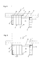
- the saw line 6 itself is a known pressure bar 18, which in the Fig. 3 to 5 is better recognizable in the frontal view.
- This is, as is known, guided to Druckbalkenstehern 23 and is lowered in the sense of a vibration-free sawing during sawing, so that the pressure bar 18, the workpiece 1 or workpiece part 9, which is to be sawn straight, in the saw line 6 on the support table. 3 imprints.
- the pressure bar 18 is then lifted off again along the pressure bar post 23 in order not to obstruct the further displacement and alignment of the workpiece 1 or the workpiece parts 9. This is known per se and need not be further explained as the fact that conveniently a suction device is integrated into the pressure bar 18.
- the pressure bar 18 has, as in the Fig. 1 to 5 schematically indicated by the terminals 38 of the suction, conveniently two ports 38 for sucking the chips resulting from sawing, which can be mutually controlled by not shown here slide in the intake so that the suction direction can be conveniently adjusted so that it corresponds to the direction in which the sawing device 8 ejects the chips. It can be cut, for example, in so-called counter-rotation, in which the sawing device moves or rotates counter to the cutting direction 31 in which the sawing device 8 is displaced during the sawing process. When sawing in the mating direction, the cutting direction 31 corresponds Conveniently the direction in which is sucked by appropriate control of the suction.
- suction is taken in the direction of the left stop rail 12 when the cutting direction 31 points in the direction of the left stop rail 12, and vice versa.
- the suction can, as previously mentioned, but alternatively or additionally by a running along the saw line gap in the support table 3, which is penetrated during sawing example of the sawing device 8, carried through.
- the suction devices are favorably segmented controlled in this sense.
- the feeding of the workpiece 1 or of the workpiece part 9 in the first working area 7 to the sawing line 6 takes place by means of a feed device 4 displaceably mounted on the guide rails 21 in the feed direction 5 and in the opposite direction.
- the actually working in the first working area 7 mainly advancing device 4 even with raised pressure bar 18 under the pressure bar 18 pass over the saw line 6 can store there sawed workpiece parts 9 and, as explained in more detail later, also workpiece parts 9 again grab and retract this against the feed 5 again at least a little way into the first working area 7 to position them for the next sawing.
- the grippers 22 of the feed device 4 can also be raised in order to be able to drive away with the entire feed device together with grippers 22 via workpieces 1 and / or workpiece parts 9 resting on the support table 3. This too is known per se and need not be explained further.
- the stop rails 12 and 13 provided according to the invention limit the first working area 7 in front of the sawing line 6 and the second working area 10 behind the sawing line 6 in the transverse direction 11.
- the stop rails 12 and 13 can, as explained at the beginning, but also only the first working area 7 or only laterally delimit the second working area 10 in the transverse direction 11, or be provided, for example, in a diagonal type of arrangement.
- the transverse direction 11 is orthogonal to the feed direction 5 and lies parallel to the plane of the drawing or the support surface of the support table 3. In other words limit the stop rails 12 and 13, the second work area 10 at least partially on the left and right.
- Relatively close behind the saw line 6 is located over the entire width of the second working area 10, in the transverse direction 11 extends longitudinally the waste discharge 24.
- This is conveniently designed as a closable opening in the support table 3.
- This closable opening can be realized for example via corresponding flaps, sliding closures or the like in the support table 3.
- the waste discharge 24 is conveniently located where the advancing device 4, the workpiece parts 9 and their ends pointing to the sawing line 6 and waste pieces 36 positioned. But this will be explained in more detail later.
- the waste pieces 36 are transported to waste disposal 27 in this exemplary embodiment. This can be realized via a corresponding known per se, in the waste discharge 24 integrated conveyor belt or the like. As a result, a particularly simple waste disposal is possible.
- the positioning device 17 is also located in the exemplary embodiment shown. This serves to convey the workpiece parts 9 produced by at least one sawing operation to one or the other stop rail 12 or 13. Furthermore, the positioning device 17, the workpiece parts 9 rotate about normal to the support surface of the support table 3 arranged rotary axes 15. Furthermore, with the positioning device 17 also advantageously raising and lowering of the workpiece parts 9 in the second working area 10 is possible. In particular, if the workpieces 1 or workpiece parts 9 are individual plates, the positioning device 17 can have one, two or more suction devices 20 or vacuum grippers with which they can be used Can grasp and manipulate workpiece parts 9.
- the positioning device 17 is advantageously movable in at least two, preferably three, spatial directions 19. These are the horizontal directions aligned in the transverse direction 11 and parallel to the feed direction 5, as well as, conveniently, those in FIG Fig. 3 19. Suitable positioning devices 17 are known per se in the form of handling systems in the prior art and need not be explained further here. For example, if the workpieces 1 or workpiece parts 9 are plate stacks, the positioning devices 17 can also be equipped with corresponding grippers. If no lifting of the workpiece parts 9 is provided, the positioning means 17 may also be simple slides or the like.
- the positioning device 17 should in any case be designed such that it can transport, rotate and / or otherwise displace workpiece parts 9 correspondingly over the entire width of the second working region 10 between the stop rails 12 and 13. In addition, in preferred embodiments, it should also be suitable for transporting workpiece parts 9 into the storage areas 16 and also picking them up there again.
- the storage areas 16 on the support table 3 can, as in the Fig. 1 and 2 shown outside of the second working area 10 laterally adjacent to the stop rails 12 and 13 may be arranged. However, a storage area 16 can also be a partial area within the first or second working area 7 and 10. For this purpose, subareas of the work areas 7 and 10 are particularly suitable, which are otherwise not required during the execution of the saw plan.
- the positioning device 17 with the suction devices 20 arranged thereon is additionally rotatable about the direction of rotation 26.
- the positioning device 17 can also be used to transport the finished end formats or workpiece parts 9 in the removal direction 28 until they are transported further in the discharge direction 28 by a further transport means (not shown here in detail).
- the mobility of the positioning device 17 by a displacement along corresponding guides 25 realized, which are partially arranged like a portal over the second working area 10. This does not have to be the case; one could also provide a known industrial robot with at least one working arm or the like which can be moved correspondingly in two or three spatial directions as a corresponding positioning device 17 or as a corresponding handling device.
- a second panel dividing plant 2 according to the invention is shown, the basic structure of which essentially corresponds to the first exemplary embodiment, so that the similarities will not be discussed again here.
- the method according to the invention can also be carried out with this panel dividing installation 2.
- the second embodiment according to Fig. 2 several, here a total of three, feed devices 4, each with a plurality of grippers 22. This makes it possible to transport a plurality of workpiece parts 9 simultaneously and independently of one another in the feed direction 5 or in the opposite direction.
- two or more workpiece parts 9, preferably adjacent to one another can be conveyed simultaneously to one of the stop rails 12 or 13 and / or two or more workpiece parts 9 simultaneously , preferably adjacent to each other, on the other stop rail 12 and 13 adjacent to the sawing line 6 further sawn.
- This is in Fig. 2 so also exemplified.
- two positioning devices 17 are provided in the second working area 10 behind the saw line 6 in this embodiment, which may otherwise be constructed according to the positioning device 17 of the first embodiment.
- a temporary store connection 29 is also provided here which controls the discharge and the Caching of residual parts during the dividing process of the workpiece 1 allows.
- Corresponding means of transport in this buffer connection 29 are not explicitly shown here. But it may be, for example, known per se, driven rollers, conveyor belts and the like.
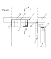
- FIGS. 3 and 5 also shown here along the pressure bar 18 and in the vertical direction on the pressure bar 18 slidably mounted aligner 37. These can, as mentioned above, serve for the exact alignment of the workpiece part or the workpiece parts by surface pressing against the stop rail 12 and 13 in preparation for the next sawing process.
- the workpiece 1 and / or at least one of the workpiece parts 9, preferably immediately before his or her sawing and / or lowering the pressure beam 18, of at least one aligner 37 for alignment in a transverse direction 11 to one of the stop rails 12 or 13 is pressed or be.
- the or the aligner 37 is or are conveniently arranged as close to the saw line 6. They are conveniently movable in transverse directions 11, and preferably also raised and lowered.
- the aligner or guides 37 can also be integrated into the support table 3 as pins, preferably in the transverse direction 11, which can preferably be raised and lowered.
- the aligners 37 are preferred individually and in the case of multiple aligners 37 independently controllable.
- Fig. 3 it is a variant in which on a saw carriage 6 movable saw carriage 30 two sawing devices 8 are arranged in the form of circular saw blades.
- saw blade 8 is a so-called scorer.
- the rear, larger blade 8 is the actual cutting process. It is particularly favorable if the sawing operation takes place in the cutting direction 31 towards the stop rail 12 or 13, against which the workpiece or workpiece part or parts 9 currently to be sawn is present.
- the saw blades 8 may be adjustable in the vertical direction to be lowered below the support surface of the support table 3 and to be able to be lifted over this, as is known per se.
- FIG. 4 A variant of this is in Fig. 4 shown.
- the saw carriage 30 two equal saw blades as a sawing device 8 available.
- the upstream in the cutting direction 31 saw blade is lowered slightly further to serve as a scorer.
- the rear saw blade is used to completely saw through the workpiece 1 or the workpiece parts 9 Fig. 4 drawn cutting direction 31 opposite cutting direction, so the saw blades 8 can be moved accordingly in the opposite direction in the vertical direction, so that in turn the front lowered further as a scorer and the rear is moved to completely saw through the workpiece 1 and the workpiece parts 9 upwards.
- both saw blades can be lowered correspondingly far.
- Fig. 5 a variant is shown in which along the saw line 6 two saw carriage 30 are movable, wherein the one saw carriage 30 is used for sawing in the one cutting direction 31 and the other saw carriage exclusively for sawing in the other, opposite cutting direction 31.
- the arrangement of scorer and main saw blade 8 and their vertical adjustability applies to both saw carriage 30 according to the first embodiment.
- the cutting direction 31 is always aligned in the direction of the stop rail 12 or 13, against which the workpiece 1 or workpiece part 9 to be sawed is present. This makes it possible, as explained in detail above, to suck off the sawdust accumulated during the sawing process as effectively as possible over the pressure bar 18 or downwards through a gap running along the sawing line 6 in the support table 3.
- Fig. 6 shows the raw plate or the workpiece to be split 1, on which the sawing plan is located.
- the saw or The cutting plan comprises the first cutting lines 32, second cutting lines 33, third cutting lines 34 and four cutting lines 35. If all these sawing operations are carried out along these cutting lines 32 to 35, this results in the final formats in the form of Fig. 6 drawn workpiece parts 9, as well as the hatched pieces 36 shown in the Fig. 7 to 21 are now in a plan view, the various process steps for processing the in Fig. 6 illustrated sawing plan.
- the inventive method can on one of the two exemplified here Plattenaufteilanlagen 2 from the Fig. 1 and 2 but also on other Plattenaufteilanlagen, which are suitable or intended to be carried out.
- Fig. 7 shows the situation when the first first cut 32 is performed at the beginning of the process.
- the feed device 4 was set in action accordingly.
- the pressure bar 18 is correspondingly lowered and then lifted again, which will not be discussed any more in the following.
- the first cuts 32 are carried out successively by advancing the workpiece 1 in the feed direction 5 in succession.
- the in Fig. 7 drawn waste piece 36 sawn off. This can then fall into it when driving over the waste dump 24. Subsequently, the first workpiece part in the form of in Fig.
- FIG. 8 shows the situation in which the last first cut 32 is performed to separate the remaining piece 36.
- the workpiece 1 does not necessarily have to be aligned with the stop rail 12.
- the workpiece 1 remains gripped in the grippers 22 of the feed device 4 the whole time.
- FIG. 9 shows the process section when the successively sawed in the course of first cuts workpiece part 9 with the in Fig. 9 still visible waste 36 is positioned above the waste dump 24.
- the pre-positioned on the right stop rail 13 for the next sawing workpiece part 9 stored in a position in which the feed device 4, the left on the left stop rail 12 filed, previously sawed, workpiece part 9 and record the voltage applied to the right stop rail 13 workpiece 9 can, without this, the feed device 4 must be moved in the feed direction or in the opposite direction.
- Fig. 10 can now be seen as in the deposited on the left stop rail 12, prepositioned workpiece part 9 of in Fig. 9 still visible remainder 36 was disposed of by the waste discharge 24 and the previously pre-positioned on the right stop rail 13 workpiece part 9 was withdrawn from the feed device 4 so far that now on this workpiece part 9, the second cuts along the in Fig. 10 drawn second cutting lines 33 can be processed sequentially. Again, the cutting direction 31 is shown towards the respective stop rail 13.
- the in Fig. 10 provided with the reference numeral 36 waste falls into this when passing over the waste dump. Otherwise, the in Fig. 11 shown end formats 9 by implementation the corresponding second sections along the second cut lines 33 from Fig. 10 generated and transported away in discharge direction 28. This does not apply to the remainder 14 resulting from these second cuts, as is shown in Fig. 11 is drawn.
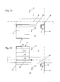
- Fig. 12 is the workpiece part 9 in turn pre-positioned on the left stop rail 12, so that the feed device at the same time let go of the right stop rail 13 abutting workpiece part 9 or remainder piece 14 and with the corresponding grippers 22 pre-positioned on the other stop rail 12 and aligned other workpiece part 9 can grab and the latter can retract counter to the feed direction 5 over the saw line 6, in order to then cut the second cuts along the in Fig.
- Fig. 22 by drawing the first, second, third and fourth cutting lines 32, 33, 34, 35 and the final formats 9 and the waste parts 36 shows an example of another sawing plan, after which a workpiece 1 is divided into the final formats.
- the same method according to the invention is used here, in that the corresponding method steps are processed one after the other.
- the workpiece 1 is in carrying out Siegismee along Clearismelinien 32 with its longest edge parallel to the saw line 6.
- Another difference from the first embodiment is that here in the second embodiment, as based on Fig.
- the other procedure basically corresponds to the procedure explained with respect to the first exemplary embodiment and does not need to be explained again here.
- each sawing or cutting plan is completely processed before the next sawing plan or the next workpiece 1 follows.
- the workpiece parts 9 successive shegerise are preferably not mixed together.
- the cutting plans can be optimized with regard to the position of the blanks and wastes so that the alternating sawing and the workpiece handling can take place in parallel as far as possible without waiting times.
Landscapes
- Life Sciences & Earth Sciences (AREA)
- Engineering & Computer Science (AREA)
- Mechanical Engineering (AREA)
- Wood Science & Technology (AREA)
- Forests & Forestry (AREA)
- Sawing (AREA)
Abstract
Verfahren zum Zersägen von zumindest einem Werkstück (1) mit einer Plattenaufteilanlage (2), wobei das Werkstück (1) auf einem Auflagetisch (3) aus einem ersten Arbeitsbereich (7) des Auflagetisches (3) der Sägelinie (6) zugeführt und mittels zumindest einer Sägeeinrichtung (8) der Plattenaufteilanlage (2) entlang der Sägelinie (6) in zumindest zwei Werkstückteile (9) zersägt wird und wobei zumindest eines der Werkstückteile (9) über die Sägelinie (6) hinweg in einen hinter der Sägelinie (6) der Plattenaufteilanlage (2) angeordneten zweiten Arbeitsbereich (10) des Auflagetisches (3) transportiert wird, wobei der erste Arbeitsbereich (7) und/oder der zweite Arbeitsbereich (10) in einer orthogonal zur Zuführrichtung (5) ausgerichteten Querrichtung (11) von zwei einander gegenüberliegenden Anschlagschienen (12, 13) begrenzt ist bzw. sind und zumindest eines der Werkstückteile (9) hin zu einer der Anschlagschienen (12, 13) befördert wird, während zumindest ein anderes der Werkstückteile (9) an der anderen Anschlagschiene (12, 13) anliegend an der Sägelinie (6) weiter zersägt wird.Method for sawing at least one workpiece (1) with a plate dividing plant (2), wherein the workpiece (1) is fed on a support table (3) from a first working area (7) of the support table (3) to the saw line (6) and by means of at least a sawing device (8) of the plate dividing plant (2) along the saw line (6) is sawed into at least two workpiece parts (9) and wherein at least one of the workpiece parts (9) over the saw line (6) in a behind the saw line (6) of the The first work area (7) and / or the second work area (10) in a direction orthogonal to the feed direction (5) aligned transverse direction (11) of two each other opposite stop rails (12, 13) is limited and / or are and at least one of the workpiece parts (9) towards one of the stop rails (12, 13) is conveyed, while at least one other of Workpiece parts (9) on the other stop rail (12, 13) adjacent to the sawing line (6) further sawn.
Description
Die vorliegende Erfindung betrifft ein Verfahren zum Zersägen von zumindest einem, aus einer Platte oder einem Plattenstapel bestehenden Werkstück mit einer Plattenaufteilanlage, wobei das Werkstück auf einem Auflagetisch der Plattenaufteilanlage liegend zum Zersägen in einer Zuführrichtung aus einem, in Zuführrichtung gesehen vor einer Sägelinie der Plattenaufteilanlage angeordneten, ersten Arbeitsbereich des Auflagetisches der Sägelinie zugeführt und mittels zumindest einer Sägeeinrichtung der Plattenaufteilanlage entlang der Sägelinie in zumindest zwei Werkstückteile zersägt wird und wobei zumindest eines der Werkstückteile über die Sägelinie hinweg in einen, in Zuführrichtung gesehen, hinter der Sägelinie der Plattenaufteilanlage angeordneten zweiten Arbeitsbereich des Auflagetisches transportiert wird.The present invention relates to a method for sawing at least one consisting of a plate or a plate stack workpiece with a Plattenaufteilanlage, the workpiece lying on a support table of the Plattenaufteilanlage for sawing in a feed direction from a, as seen in the feed direction in front of a sawing line of the Plattenaufteilanlage , at least one of the workpiece parts over the saw line away in a, seen in the feed direction, behind the sawing line of the Plattenaufteilanlage arranged second working area of the Supporting table is transported.
Plattenaufteilanlagen werden z.B. bei der Möbelfertigung dazu verwendet, Werkstücke, welche aus Platten oder Plattenstapeln bestehen, zuzusägen bis sie in Werkstückteile bzw. Zuschnitte zerteilt sind, die dann der endgültigen gewünschten Größe entsprechen. In Folge der fortschreitenden Individualisierung, insbesondere im Bereich der Möbelfertigung, ergeben sich für den Zuschnitt der Werkstücke immer geringere Stückzahlen von Werkstückteilen mit derselben Endgröße bzw. - geometrie.Panel dividers are used e.g. used in furniture production to saw workpieces, which consist of plates or plate stacks, sawed until they are divided into workpiece parts or blanks, which then correspond to the final desired size. As a result of the progressive individualization, in particular in the field of furniture production, resulting in the cutting of the workpieces ever smaller quantities of workpiece parts with the same final size or - geometry.
Um den Abfall möglichst gering zu halten, ergeben sich dadurch immer komplexere Sägepläne, denen folgend ein Werkstück zersägt werden soll. Bei der Abarbeitung dieser Säge-, Schnitt- bzw. Aufteilpläne werden die Werkstückteile mehrfach einer Sägelinie zugeführt, bis sie in Werkstückteile mit der endgültigen Größe zerteilt sind.In order to keep the waste as low as possible, this results in increasingly complex sawing plans, which are to be sawn following a workpiece. During the execution of these sawing, cutting or splitting plans, the workpiece parts are repeatedly fed to a sawing line until they are divided into workpiece parts with the final size.
Um diese komplexen Sägepläne vollautomatisch abarbeiten zu können, werden bis jetzt aufwendige Plattenaufteilanlagen mit mehreren Sägen und/oder aufwendiger Fördertechnik zum Transport der Werkstückteile eingesetzt, wie dies z.B. in der
Ein gattungsgemäßes Verfahren wird z.B. in der
Aufgabe der Erfindung ist es, ein gattungsgemäßes Verfahren dahingehend zu verbessern, dass auch komplexe Sägepläne effektiv mit einer vergleichsweise einfachen Plattenaufteilanlage einfach und schnell abgearbeitet werden können.The object of the invention is to improve a generic method to the extent that even complex Sägepläne can be processed easily and quickly effectively with a comparatively simple Plattenaufteilanlage.
Die Erfindung schlägt hierfür vor, dass der erste Arbeitsbereich und/oder der zweite Arbeitsbereich in einer orthogonal zur Zuführrichtung ausgerichteten Querrichtung von zwei einander gegenüberliegenden Anschlagschienen begrenzt ist bzw. sind und zumindest eines der Werkstückteile hin zu einer der Anschlagschienen befördert wird, während zumindest ein anderes der Werkstückteile (9) an der anderen Anschlagschiene (12, 13) anliegend an der Sägelinie (6) weiter zersägt wird.The invention proposes for this purpose that the first working area and / or the second working area is bounded in a direction orthogonal to the feed direction transverse direction of two opposing stop rails and at least one of the workpiece parts is transported to one of the stop rails, while at least one other the workpiece parts (9) on the other stop rail (12, 13) adjacent to the saw line (6) further sawn.
Es ist somit ein Grundgedanke der Erfindung, zumindest eines der Werkstückteile hin zu einer den ersten Arbeitsbereich und/oder den zweiten Arbeitsbereich seitlich begrenzenden Anschlagschiene zu befördern, während zumindest ein anderes der Werkstückteile an der anderen Anschlagschiene anliegend an der Sägelinie weiter zersägt wird. Hierdurch kann die Plattenaufteilanlage relativ einfach ausgestaltet sein und trotzdem sehr effektiv auch komplizierte Sägepläne mit verschiedenen Endformaten abarbeiten. Bezüglich der Formulierung, dass das Befördern des zumindest einen Werkstückteils hin zur einen Anschlagschiene während des Zersägens des zumindest anderen Werkstückteils anliegend an der anderen Anschlagschiene erfolgt, ist darauf hinzuweisen, dass diese beiden Vorgänge durchaus unterschiedlich lang dauern können. Bevorzugt ist dabei vorgesehen, dass das erwähnte Befördern schneller geht als das Zersägen, da dann sichergestellt ist, dass die Sägevorgänge schnellstmöglich hintereinander durchgeführt werden können und die Sägeeinrichtung im Sinne einer möglichst raschen Abarbeitung des Sägeplans zeitoptimiert eingesetzt werden kann. Die Formulierung mit "während" bedeutet somit, dass sich das genannte Befördern des zumindest einen Werkstückteils mit dem genannten Zersägen des zumindest einen anderen Werkstückteils zumindest zeitlich überlappt.It is thus a basic idea of the invention to convey at least one of the workpiece parts to a stop rail laterally delimiting the first work area and / or the second work area, while at least one other of the workpiece parts is sawed on to the other stop rail adjoining the saw line. As a result, the panel splitter can be designed relatively simple and still work very effectively even complicated Sägepläne with different final formats. With regard to the formulation that the conveying of the at least one workpiece part towards a stop rail takes place during the sawing of the at least one workpiece part adjacent to the other stop rail, it should be pointed out that these two processes can definitely take different lengths. Preferably, it is provided that the mentioned conveying is faster than the sawing, since then it is ensured that the sawing operations can be carried out as quickly as possible in succession and the sawing device in terms of the fastest possible processing of Sawing plan can be used time-optimized. The wording "during" thus means that the said conveying of the at least one workpiece part overlaps with the said sawing of the at least one other workpiece part at least temporally.
Die Anschlagschienen können nur den ersten Arbeitsbereich oder nur den zweiten Arbeitsbereich oder beide Arbeitsbereiche in Querrichtung seitlich begrenzen. Bezüglich einer zur Zuführrichtung parallelen Symmetrieachse achsensymmetrische Anordnungen der Anschlagschienen sind dabei bevorzugt. Es kann aber auch eine diagonale Art der Anordnung der Anschlagschienen gewählt werden, z.B. indem die eine Anschlagschiene den ersten Arbeitsbereich auf der einen Seite begrenzt und eine zweite, gegenüberliegende Anschlagschiene den zweiten Arbeitsbereich auf der gegenüberliegenden Seite begrenzt. All dies sind mögliche Ausgestaltungsformen der Erfindung.The stop rails can limit only the first work area or only the second work area or both work areas in the transverse direction laterally. With respect to an axis of symmetry parallel to the feed direction, axisymmetric arrangements of the stop rails are preferred. However, it is also possible to choose a diagonal type of arrangement of the stop rails, e.g. in that the one stop rail delimits the first work area on one side and a second, opposite stop rail limits the second work area on the opposite side. All of these are possible embodiments of the invention.
Zur Zuführrichtung ist anzumerken, dass dies die Richtung ist, in der das Werkstück oder die Werkstückteile in der Regel unmittelbar vor oder beim Sägevorgang selbst der Sägelinie zugeführt werden. Dies bedeutet aber nicht zwingend, dass das Werkstück also z.B. die Rohplatte bzw. der Rohplattenstapel, vor Beginn des erfindungsgemäßen Verfahrens nicht auch erst einmal entgegen der Zuführrichtung, z.B. manuel oder mittels der weiter unten genannten Vorschubeinrichtung, in den ersten Arbeitsbereich eingeschoben oder eingezogen werden können.It should be noted with respect to the feed direction that this is the direction in which the workpiece or workpiece parts are usually fed to the sawing line directly before or during the sawing process. However, this does not necessarily mean that the workpiece, e.g. the raw plate or the raw plate stack, before the start of the method according to the invention not once against the feeding direction, e.g. manuel or by means of the feed device mentioned below, can be inserted or retracted in the first work area.
Beim Befördern der Werkstückteile hin zu einer der Anschlagschienen kann bereits ein Ausrichten an der Anschlagschiene erfolgen. Dies muss aber nicht sein. Das exakte Ausrichten des Werkstückteils bzw. der Werkstückteile durch flächiges Andrücken an die Anschlagschiene in Vorbereitung auf den nächsten Sägevorgang kann auch separat z.B. erst unmittelbar vor dem Weiterzersägen des zumindest einen Werkstückteils erfolgen. Hierzu kann z.B. vorgesehen sein, dass das Werkstück und/oder zumindest eines der Werkstückteile, vorzugsweise unmittelbar vor seinem bzw. ihrem Zersägen und/oder Absenken des Druckbalkens, von zumindest einem Ausrichter, vorzugsweise der Plattenaufteilanlage, zur Ausrichtung in einer Querrichtung an eine der Anschlagschienen angedrückt wird bzw. werden. Der oder die Ausrichter ist bzw. sind günstigerweise möglichst nah an der Sägelinie angeordnet. Dies kann z.B. realisiert werden, indem sie verfahrbar, und vorzugsweise auch heb- und senkbar, an dem weiter hinten noch erwähnten Druckbalken oder am weiter hinten ebenfalls noch genauer geschilderten Sägewagen angeordnet sind. Ausrichter können auch als, insbesondere in Querrichtung verfahrbare, vorzugsweise heb- und absenkbare, Zapfen oder Nocken in den Auflagetisch integriert sein.When conveying the workpiece parts towards one of the stop rails can already be done aligning the stop rail. But this does not have to be. The exact alignment of the workpiece part or the workpiece parts by pressing flat against the stop rail in preparation for the next sawing can also be done separately eg only immediately before Weiterzersägen the at least one workpiece part. For this purpose, it can be provided, for example, that the workpiece and / or at least one of the workpiece parts, preferably immediately before his or her sawing and / or lowering of the pressure bar, of at least one aligner, preferably the panel splitter, for alignment in one Transverse direction is pressed against one of the stop rails or be. The organizer (s) is / are conveniently located as close as possible to the saw line. This can be realized, for example, by being movable, and preferably also raised and lowered, arranged on the pressure bar mentioned further on at the back or on the saw carriage also described in more detail further down. Aligners can also be integrated as, in particular in the transverse direction movable, preferably raised and lowered, pins or cams in the support table.
Besonders bevorzugte Ausgestaltungsformen der Erfindung vor, dass in nacheinander durchgeführten Verfahrensschritten abwechselnd in einem der Verfahrensschritte zumindest eines der Werkstückteile hin zu einer der Anschlagschienen befördert wird, während zumindest ein anderes der Werkstückteile an der anderen Anschlagschiene anliegend an der Sägelinie weiter zersägt wird und in einem später durchgeführten Verfahrensschritt zumindest eines der Werkstückteile an der einen der Anschlagschienen anliegend weiter an der Sägelinie zersägt wird, während zumindest ein anderes der Werkstückteile hin zu der anderen Anschlagschiene befördert wird.Particularly preferred embodiments of the invention that in successive steps alternately carried in one of the steps at least one of the workpiece parts to one of the stop rails, while at least another of the workpiece parts on the other stop rail adjacent to the saw line further sawed and in a later performed method step at least one of the workpiece parts on the one of the stop rails adjacent further sawed on the saw line, while at least one other of the workpiece parts is transported to the other stop rail.
Es wird somit eine bevorzugte alternierende Vorgehensweise vorgeschlagen, bei der zumindest ein Werkstück auf die eine Seite an eine der Anschlagschienen befördert und damit für den nächsten Sägevorgang vorpositioniert wird, während zumindest ein anderes Werkstückteil an der anderen Anschlagschiene anliegend weiter zersägt wird. Sind alle an diesem Werkstückteil bzw. diesen Werkstückteilen in diesem Verfahrensschritt durchgeführten Sägevorgänge vollführt, so können die Werkstückteile, welche bereits ihre endgültige Dimension erreicht haben, abtransportiert werden. Die anderen Werkstückteile bleiben dann an der Anschlagschiene liegen und es wird nun das bzw. die bereits für den nächsten Sägevorgang vorbereitete Werkstückteil(e) an der auf der anderen Seite liegenden Anschlagschiene weiter zersägt. Dieses Abwechseln der Bearbeitung auf den verschiedenen Seiten des ersten und/oder zweiten Arbeitsbereichs, an jeweils einer der Anschlagschienen, kann so lange alternierend bzw. abwechselnd fortgeführt werden, bis jedes der Werkstückteile seine endgültige Dimension erreicht hat. Es können so effektiv und einfach mit relativ geringem maschinentechnischen Aufwand Sägepläne mit beliebig vielen Schnittebenen, also mit Erst-, Zweit-, Dritt- und Viertschnittlinien usw. realisiert werden. Das Verfahren kann auf Plattenaufteilanlagen mit manuellem, teilautomatisierten oder vollautomatisierten Handling der Werkstücke vor und hinter der Sägelinie angewendet werden. Die nach diesem Verfahren arbeitetenden Plattenaufteilanlagen können sehr kompakt aufgebaut sein und bieten gleichzeitig eine hohe Flexiblität und eine hohe Aufteilleistung.Thus, a preferred alternating procedure is proposed in which at least one workpiece is conveyed on one side to one of the stop rails and thus pre-positioned for the next sawing operation, while at least one other workpiece part is further sawed on the other stop rail. If all sawing operations carried out on this workpiece part or workpiece parts in this method step are carried out, the workpiece parts which have already reached their final dimension can be removed. The other parts of the workpiece then remain on the stop rail and it is now that or the already prepared for the next sawing workpiece workpiece (e) further sawed on the lying on the other side stop rail. This alternation of machining on the different sides of the first and / or second working area, on each one of the stop rails, can be continued alternately until each of the workpiece parts has reached its final dimension. It Sawing plans with as many cutting planes as possible, ie with first, second, third and fourth cutting lines, etc., can be realized in such an effective and simple manner with relatively little mechanical outlay. The method can be applied to panel dividers with manual, semi-automated or fully automated handling of the workpieces in front of and behind the saw line. The plate dividing systems working according to this method can be very compact and at the same time offer high flexibility and a high dividing performance.
In diesem Sinne sehen besonders bevorzugte Ausgestaltungsformen vor, dass alle Sägevorgänge bis zur vollständigen Aufteilung des Werkstücks an der einen Sägelinie der Plattenaufteilanlage durchgeführt werden. Erfindungsgemäße Verfahren können somit an einer Plattenaufteilanlage durchgeführt werden, welche nur eine einzige Sägelinie aufweist. Die Sägelinie kann über eine einzige aber auch über mehrere Sägeeinrichtungen verfügen, welche entlang der Sägelinie verfahrbar sind, um den jeweiligen Sägevorgang durchzuführen. Es kann sich z.B. um an sich bekannte Unterflurkreissägen handeln, welche für den Sägevorgang mit ihrem Sägeblatt über die Auflageebene des Auflagetisches angehoben und für Rückfahrten entlang der Sägelinie unter die Auflageebene abgesenkt werden können. Die Sägeeinrichtungen können ein oder mehrere, vorzugsweise zwei Sägeblätter aufweisen, wobei eines der Sägeblätter z.B. als Vorritzter und das zweite der Sägeblätter dann als den eigentlichen Sägevorgang durchführendes Sägeblatt verwendet werden. Die Sägeeinrichtungen weisen günstigerweise einen Sägewagen auf, mit dem sie bzw. die Sägeblätter entlang der Sägelinie verfahrbar sind. Solche Sägeeinrichtungen sind in Form von Unterflurkreissägen bekannt. Der eigentliche Sägevorgang wird günstigerweise in Richtung hin zu der Anlageschiene, an der das zu zersägende Werkstück oder Werkstückteil gerade anliegt, vorgenommen.In this sense, particularly preferred embodiments provide that all sawing operations are carried out until the complete division of the workpiece on the one sawing line of the panel-splitting installation. Methods according to the invention can thus be carried out on a panel-splitting machine which has only a single sawing line. The sawing line may have a single but also several sawing devices which can be moved along the sawing line in order to carry out the respective sawing process. It can be e.g. to be known underground circular saws, which can be raised for the sawing process with her saw blade on the support plane of the support table and lowered for return travel along the saw line under the support plane. The sawing means may comprise one or more, preferably two, saw blades, one of the saw blades e.g. as a scorer and the second of the saw blades then be used as the actual sawing performing saw blade. The sawing means conveniently have a saw carriage with which they or the saw blades can be moved along the sawing line. Such sawing devices are known in the form of underfloor circular saws. The actual sawing process is favorably carried out in the direction of the abutment rail against which the workpiece or workpiece part to be sawn is being applied.
Im ersten Arbeitsbereich des Auflagetisches ist günstigerweise zumindest eine Vorschubeinrichtung vorgesehen. Mit dieser können die zu zersägenden Werkstücke bzw. Werkstückteile in Zuführrichtung hin zur Sägelinie transportiert werden. Günstigerweise ist mit der zumindest einen Vorschubeinrichtung aber auch ein Rücktransport entgegen der Zuführrichtung möglich. Genauso gut kann es vorgesehen sein, dass die Vorschubeinrichtung bzw. die Vorschubeinrichtungen über die Sägelinie hinweg zumindest ein Stück weit in den zweiten Arbeitsbereich hineingreifen kann bzw. können. Allgemein gesprochen, ist bevorzugt vorgesehen, dass das Werkstück und/oder zumindest eines der Werkstückteile von zumindest einer Vorschubeinrichtung der Plattenaufteilanlage in oder entgegen der Zuführrichtung im ersten Arbeitsbereich und/oder im zweiten Arbeitsbereich transportiert wird bzw. werden. Geeignete Vorschubeinrichtungen sind beim Stand der Technik grundsätzlich in verschiedenen Ausgestaltungsformen bekannt. Sie weisen bevorzugt einen oder mehrere Greifer auf, mit dem sie die Werkstücke bzw. Werkstückteile greifen und festhalten können. Darüber hinaus weisen sie auch einen geeigneten Antrieb zur Bewegung der Vorschubeinrichtung, gegebenenfalls samt Werkstück bzw. Werkstückteil in Zuführrichtung und auch in Gegenrichtung auf. Die zumindest eine Vorschubeinrichtung und die gegebenenfalls vorhandenen Greifer sind günstigerweise höhenverstellbar, so dass sie über einzelne Werkstücke auch hinweggefahren werden können. Erfindungsgemäße Verfahren können den Transport mittels einer oder auch mehrerer solcher Vorschubeinrichtungen im ersten und auch im zweiten Arbeitsbereich vorsehen. Es sind aber auch Varianten erfindungsgemäßer Verfahren denkbar, bei denen das Zuführen der Werkstücke oder Werkstückteile in Zuführrichtung oder auch das Zurückziehen in Gegenrichtung im ersten und auch im zweiten Arbeitsbereich manuell durchgeführt wird.In the first working area of the support table, at least one feed device is advantageously provided. With this, the workpieces or workpiece parts to be sawn can be transported in the feed direction to the sawing line. Conveniently, with the at least one feed device but also a Return transport possible contrary to the feed direction. It can just as well be provided that the feed device or the feed devices can reach into the second work area at least a little beyond the saw line. Generally speaking, it is preferably provided that the workpiece and / or at least one of the workpiece parts is / are transported by at least one feed device of the panel dividing installation in or against the feed direction in the first working area and / or in the second working area. Suitable feed devices are known in the prior art in principle in various embodiments. They preferably have one or more grippers, with which they can grip and hold the workpieces or workpiece parts. In addition, they also have a suitable drive for moving the feed device, possibly together with the workpiece or workpiece part in the feed direction and also in the opposite direction. The at least one feed device and possibly existing grippers are conveniently adjustable in height, so that they can also be passed over individual workpieces. Inventive methods can provide transport by means of one or more such feed devices in the first and also in the second working range. However, variants of methods according to the invention are also conceivable in which the feeding of the workpieces or workpiece parts in the feed direction or else the retraction in the opposite direction is carried out manually in the first and also in the second working range.
Für die Ausbildung des Auflagetisches sowohl im ersten als auch im zweiten Arbeitsbereich können verschiedene, beim Stand der Technik an sich bekannte Varianten herangezogen werden. Um die Reibung zwischen Auflagetisch und Werkstück bzw. Werkstückteil möglichst gering zu halten sehen bevorzugte Varianten vor, dass die Auflagefläche des Auflagetisches auf der das Werkstück bzw. die Werkstücke aufliegen, als Rollenbahn, als Luftkissenplatte, als Bürstenoberfläche oder dergleichen ausgebildet sind.For the formation of the support table both in the first and in the second working range, different variants known per se in the prior art can be used. To keep the friction between the support table and the workpiece or workpiece part as low as possible, preferred variants provide that the bearing surface of the support table on which the workpiece or the workpieces rest, are designed as a roller conveyor, as an air cushion plate, as a brush surface or the like.
Die Sägelinie verläuft günstigerweise linear bzw. gerade. Bevorzugt erstreckt sie sich über die gesamte Breite des ersten und zweiten Arbeitsbereichs. Die Anschlagschienen, welche den ersten und/oder zweiten Arbeitsbereich in Querrichtung begrenzen, sind bevorzugt jeweils parallel zur Zuführrichtung ausgerichtet. Sie liegen also günstigerweise auch parallel zueinander und sind bevorzugt justierbar. Es handelt sich bei den Anschlagschienen somit nicht um beliebige Flächen sondern um sehr exakt in ihrer Lage und Richtung ausgerichtete Anschlagschienen, welche als Anschläge vorgesehen sind und damit eine Möglichkeit bilden, die Werkstückteile für die weitere Verarbeitung exakt so auszurichten, wie dies für die folgenden Sägevorgänge benötigt wird.The saw line is conveniently linear or straight. Preferably, it extends over the entire width of the first and second working area. The Stop rails, which limit the first and / or second working area in the transverse direction, are preferably aligned parallel to the feed direction. So they are conveniently also parallel to each other and are preferably adjustable. It is in the stop rails thus not to any surfaces but aligned very accurately in their position and direction stop rails, which are provided as stops and thus provide a way to align the workpiece parts for further processing exactly as for the following Sägevorgänge is needed.
Zum Begriff der Werkstückteile sei darauf hingewiesen, dass ein Werkstückteil entweder durch Zersägen des Werkstücks oder aber auch durch Zersägen eines, durch einen vorherigen Sägevorgang hergestellten Werkstückteils entstehen kann. Werkstückteile sind also Teile des Werkstücks, welche durch zumindest einen, aber auch durch mehrere Sägevorgänge erzeugt wurden. Diese Werkstückteile können jeweils weiter zersägt werden, um noch kleinere Werkstückteile herzustellen. Sie können aber auch dem jeweiligen Endformat entsprechen und nicht weiter zersägt werden. Werkstückteile sind also z.B. Teilplatten, Plattenstreifen oder entsprechende Stapel von Teilplatten oder Plattenstreifen oder eben entsprechende Zwischen- oder Endformate.It should be pointed out to the term of the workpiece parts that a workpiece part can be produced either by sawing the workpiece or else by sawing a workpiece part produced by a previous sawing process. Workpiece parts are thus parts of the workpiece, which were produced by at least one, but also by several sawing operations. These workpiece parts can each be sawn further to produce even smaller workpiece parts. But they can also correspond to the respective end format and not be sawn further. Workpiece parts are thus e.g. Partial plates, plate strips or corresponding stacks of partial plates or plate strips or just corresponding intermediate or final formats.
Günstigerweise sieht das erfindungsgemäße Verfahren vor, dass bei einem Sägevorgang das Werkstück oder das Werkstückteil bzw. die Werkstückteile immer entlang seiner gesamten Breite entlang der Sägelinie komplett zersägt wird bzw. werden.Conveniently, the method according to the invention provides that during a sawing process the workpiece or the workpiece part or the workpiece parts are always completely sawed along its entire width along the saw line.
Bei bevorzugten Varianten des erfindungsgemäßen Verfahrens kann auch vorgesehen sein, dass zumindest ein Werkstückteil, welches an einer der Anschlagschienen anliegend zersägt wurde, zur Weiterverarbeitung anschließend hin zur anderen Anschlagschiene befördert wird. Es kann somit ein Hin- und Hertransport der Werkstückteile zwischen den Anschlagschienen vorgesehen sein. Weiters sehen bevorzugte Varianten des erfindungsgemäßen Verfahrens vor, dass zumindest eines der Werkstückteile vor dem Weiterzersägen dieses Werkstückteils, vorzugsweise im zweiten Arbeitsbereich, auf dem Auflagetisch um eine zum Auflagetisch normal stehende Drehachse gedreht wird und hin zu einer der Anschlagschienen befördert wird.In preferred variants of the method according to the invention, provision may also be made for at least one workpiece part, which has been sawed on one of the stop rails, to be conveyed subsequently to the other stop rail for further processing. It can thus be provided between the stop rails a back and forth transport of the workpiece parts. Furthermore, preferred variants of the method according to the invention provide that at least one of the workpiece parts is rotated on the support table about a rotation axis normal to the support table before further sawing this workpiece part, preferably in the second work area, and is conveyed to one of the stop rails.
Das Bewegen der Werkstückteile im zweiten Arbeitsbereich, also das Befördern zur jeweiligen Anschlagschiene, das Drehen und/oder auch das Entnehmen oder Auslagern in einen später noch genannten Ablagebereich, kann bei erfindungsgemäßem Verfahren grundsätzlich auch manuell durchgeführt werden. Bevorzugte Ausgestaltungsformen der Erfindung sehen aber vor, dass die Werkstückteile im zweiten Arbeitsbereich von zumindest einer, insbesondere zusätzlich zur Vorschubeinrichtung vorgesehenen, Positioniereinrichtung der Plattenaufteilanlage hin zu einer der Anschlagschienen befördert und/oder um eine zum Auflagetisch normal ausgerichtet stehende Drehachse gedreht und/oder in einem Ablagebereich auf dem Auflagetisch zwischengelagert werden. Bei dieser Positioniereinrichtung handelt es sich somit um ein Handlinggerät, welches die Werkstückteile im zweiten Arbeitsbereich bewegt, um sie in Vorbereitung eines späteren Sägevorgangs abzulegen bzw. vorzupositionieren oder um eine normal zum Auflagetisch angeordnete Drehachse zu drehen. Weiters kann mit der Positioniereinrichtung auch ein Zwischenlagern der Werkstückteile in einem Ablagebereich erfolgen. Die Positioniereinrichtung kann zumindest eine, in zumindest zwei, vorzugsweise in drei Raumrichtungen verfahrbare und gegebenenfalls auch um eine normal zum Auflagetisch stehende Drehachse drehbare Einrichtung zum Aufnehmen bzw. Greifen und Transportieren der Werkstückteile aufweisen. Bei dieser Einrichtung kann es sich um zumindest eine Ansaugeinrichtung zum Ansaugen der Werkstückteile handeln. Solche Ansaugeinrichtungen sind als Vakuumgreifer grundsätzlich bekannt. Günstigerweise weist die Positioniereinrichtung mehrere Ansaugeinrichtungen auf, die einzeln oder in Gruppen aktivierbar sind um verschieden große Werkstückteile effektiv aufnehmen bzw. ansaugen und transportieren zu können. Es sind aber auch andere Einrichtungen bzw. Greifer denkbar, mit denen die Positioniereinrichtung die Werkstückteile greifen, transportieren, drehen und/oder aus dem zweiten Arbeitsbereich auslagern und in diesen wieder einführen kann, insbesondere wenn es um das Handling von Werkstücken bzw. Werkstückteilen geht, welche aus Plattenstapeln bestehen. Im Sinne einer raschen Vorgehensweise kann bei erfindungsgemäßen Verfahren auch eine Plattenaufteilanlage mehrere Positioniereinrichtungen dieser Art aufweisen.Moving the workpiece parts in the second working area, ie conveying to the respective stop rail, turning and / or removal or removal into a later mentioned storage area, can in principle be carried out manually in the inventive method. Preferred embodiments of the invention provide, however, that the workpiece parts in the second working area of at least one, in particular in addition to the feed device, provided positioning of the Plattenaufteilanlage promoted to one of the stop rails and / or rotated about a support table normal aligned rotation axis and / or in one Storage area be stored on the support table. This positioning device is thus a handling device which moves the workpiece parts in the second working area in order to deposit or pre-position them in preparation for a later sawing process or to turn a rotation axis arranged normal to the support table. Furthermore, the positioning device can also be used to temporarily store the workpiece parts in a storage area. The positioning device can have at least one device which can be moved in at least two, preferably in three spatial directions and possibly also rotatable about a rotation axis normal to the support table for receiving or gripping and transporting the workpiece parts. This device may be at least one suction device for sucking the workpiece parts. Such suction devices are basically known as vacuum grippers. Conveniently, the positioning device has a plurality of suction devices which can be activated individually or in groups in order to effectively absorb or suck in and transport different sized workpiece parts. But there are also other devices or grippers conceivable with which the positioning Grasping workpiece parts, transport, rotate and / or outsource from the second work area and can reintroduce into this, especially when it comes to the handling of workpieces or workpiece parts, which consist of plate stacks. In the sense of a rapid procedure, in the case of the method according to the invention, a panel dividing installation can also have a plurality of positioning units of this type.
Bei entsprechend aufwendigen Sägeplänen kann es sein, dass ein Werkstück oder ein Werkstückteil in mehr als zwei, also drei, vier oder fünf Werkstückteile zersägt wird, wobei im nächsten Verfahrensschritt eines der Werkstückteile hin zu einer der Anschlagschienen befördert wird, das zweite der Werkstückteile an der anderen Anschlagschiene anliegend zersägt wird und die weiteren Werkstückteile derweil zwischengelagert werden müssen. Bevorzugte Ausgestaltungsformen des Verfahrens sehen hierzu vor, dass zusätzlich zum Befördern eines der Werkstückteile hin zu einer der Anschlagschienen und während des Zersägens des anderen der Werkstückteile anliegend an der anderen Anschlagschiene an der Sägelinie zumindest ein zusätzliches Werkstückteil in zumindest einem Ablagebereich auf dem Auflagetisch zwischengelagert wird. Der Ablagebereich auf dem Auflagetisch kann grundsätzlich auch im ersten Arbeitsbereich und/oder im zweiten Arbeitsbereich angeordnet sein. Bevorzugte Varianten sehen aber vor, dass der Ablagebereich auf dem Auflagetisch außerhalb des ersten Arbeitsbereichs und außerhalb des zweiten Arbeitsbereichs angeordnet ist. Im Sinne von kurzen Transportwegen und einer guten Erreichbarkeit der Ablagebereiche sehen besonders bevorzugte Varianten dann vor, dass der Ablagebereich bzw. die Ablagebereiche in der Querrichtung seitlich neben dem ersten und/oder zweiten Arbeitsbereich angeordnet ist bzw. sind.In accordance with elaborate Sägeplänen it may be that a workpiece or a workpiece part is sawed in more than two, so three, four or five workpiece parts, in the next step, one of the workpiece parts is transported to one of the stop rails, the second of the workpiece parts on the other stop rail adjacent sawing is sawed and the other parts of the workpiece must meanwhile be stored. Preferred embodiments of the method provide for this purpose that in addition to conveying one of the workpiece parts towards one of the stop rails and during the sawing of the other of the workpiece parts adjacent to the other stop rail on the saw line at least one additional workpiece part is stored in at least one storage area on the support table. The storage area on the support table can in principle also be arranged in the first work area and / or in the second work area. However, preferred variants provide that the storage area is arranged on the support table outside the first work area and outside the second work area. In the sense of short transport paths and good accessibility of the storage areas, particularly preferred variants then provide for the storage area or the storage areas to be arranged laterally next to the first and / or second work area in the transverse direction.
Im Sinne einer besonders effektiven und schnellen Vorgehensweise sehen besonders bevorzugte Ausgestaltungsformen des erfindungsgemäßen Verfahrens vor, dass das zumindest eine hin zu einer der Anschlagschienen beförderte Werkstückteil in eine Position gebracht wird, in der es von der Vorschubeinrichtung bei Verharren der Vorschubeinrichtung in der Zuführrichtung wieder aufgenommen werden kann, während ein Reststück des zumindest einen anderen der Werkstückteile nach dessen Zersägen an der Sägelinie von der Vorschubeinrichtung an der anderen Anschlagschiene abgelegt wird. Hierbei ist es möglich, mit der Vorschubeinrichtung das zumindest eine im nächsten Sägevorgang zu zersägende Werkstückteil zu greifen und gleichzeitig das zumindest eine Reststück des zumindest einen vorab zersägten Werkstückteils loszulassen, ohne dass hierzu die Vorschubeinrichtung parallel zur Zuführrichtung ihre Lage ändern müsste. Die Position, in der das zumindest eine Werkstückteil abgelegt wird, befindet sich günstigerweise im Bereich eines Abfallabwurfs des Auflagetisches, durch den hindurch Abfallstücke, welche nicht weiter benötigt werden, einer Abfallentsorgung zugeführt werden können. Es kann sich bei den an sich bekannten Abfallabwürfen z.B. um durch Klappen oder anderweitig verschließbare Öffnungen im Auflagetisch handeln.In terms of a particularly effective and rapid procedure, particularly preferred embodiments of the method according to the invention provide that the at least one workpiece part conveyed towards one of the stop rails is brought into a position in which it is picked up again by the feed device when the feed device remains in the feed direction can be, while a remainder of the at least one other of the workpiece parts is stored after the sawing of the saw line from the feed device to the other stop rail. In this case, it is possible to grasp with the feed device the at least one workpiece part to be sawed in the next sawing operation and at the same time release the at least one remnant of the at least one pre-sawed workpiece part, without the feed device having to change its position parallel to the feed direction. The position in which the at least one workpiece part is deposited is conveniently located in the region of a waste discharge of the support table, through which waste pieces which are no longer needed can be supplied to waste disposal. For example, the waste drops known per se may be flaps or otherwise closable openings in the support table.
Um den Sägevorgang möglichst vibrationsarm ausgestalten zu können, sehen bevorzugte Ausgestaltungsformen des Verfahrens vor, dass das zu zersägende Werkstück oder Werkstückteil von einem Druckbalken im Bereich der Sägelinie an den Auflagetisch angedrückt wird. Geeignete Druckbalken für Plattenaufteilanlagen sind beim Stand der Technik an sich bekannt. Sie können auf den Auflagetisch bzw. das darauf aufliegende Werkstück bzw. Werkstückteil bzw. die Werkstückteile abgesenkt und wieder abgehoben werden. In der Regel sind sie vertikal verfahrbar. Besonders bevorzugte Ausgestaltungsformen von solchen Druckbalken haben eine integrierte Absaugung, was an sich auch bekannt ist. Eine Absaugung der Sägespäne kann alternativ oder zusätzlich auch durch einen im Bereich der Sägelinie im Auflagetisch vorgesehenen Spalt erfolgen, durch die die Sägeeinrichtung bzw. das Sägeblatt oder die Sägeblätter hindurchtreten. Bevorzugt ist jedenfalls vorgesehen, dass die Vorschubeinrichtung bei angehobenen Druckbalken unter dem Druckbalken hindurchfahren kann, um zumindest ein Stück weit in den zweiten Arbeitsbereich hineingreifen zu können.In order to be able to design the sawing process with as little vibration as possible, preferred embodiments of the method provide that the workpiece or workpiece part to be sawn is pressed against the support table by a pressure bar in the region of the saw line. Suitable pressure bars for panel dividing systems are known per se in the prior art. They can be lowered onto the support table or the workpiece resting thereon or workpiece part or the workpiece parts and lifted off again. As a rule, they can be moved vertically. Particularly preferred embodiments of such pressure bar have an integrated suction, which is also known per se. Suction of the sawdust can alternatively or additionally also be effected by a gap provided in the area of the saw line in the support table, through which the sawing device or the saw blade or the saw blades pass. In any case, it is preferably provided that the feed device can pass under the pressure bar when the pressure bar is raised in order to be able to reach into the second working area at least to some extent.
Neben dem bereits genannten Verfahren betrifft die Erfindung auch eine Plattenaufteilanlage, welche zumindest Folgendes aufweist:
- einen Auflagetisch zum darauf Auflegen zumindest eines, aus einer Platte oder einem Plattenstapel bestehenden Werkstücks und
- eine Zuführrichtung für die Zuführung des Werkstücks zu einer Sägelinie der Plattenaufteilanlage und
- einen, in Zuführrichtung gesehen vor der Sägelinie angeordneten, ersten Arbeitsbereich des Auflagetisches und
- zumindest eine Sägeeinrichtung zum Zersägen des Werkstücks entlang der Sägelinie in zumindest zwei Werkstückteile und
- einen, in Zuführrichtung gesehen hinter der Sägelinie der Plattenaufteilanlage angeordneten, zweiten Arbeitsbereich des Auflagetisches,
- a support table for laying at least one, consisting of a plate or a plate stack workpiece and
- a feed direction for the supply of the workpiece to a sawing line of the Plattenaufteilanlage and
- a, seen in the feed before the saw line arranged, first working area of the support table and
- at least one sawing device for sawing the workpiece along the sawing line in at least two workpiece parts and
- a, arranged in the feed direction behind the sawing line of the panel splitter, second working area of the support table,
Erfindungsgemäße Plattenaufteilanlagen weisen in bevorzugten Ausgestaltungsformen die oben bezüglich des Verfahrens bereits genannten Bauteile, Merkmale und Eigenschaften auf, auch wenn diese im Sinne einer gerafften Darstellung hier nicht noch einmal explizit wiederholt werden.In accordance with a preferred embodiment of the present invention, panel dividing systems have the components, features and properties already mentioned above with respect to the method, even if they are not explicitly repeated here in the sense of a shirred representation.
Weitere Merkmale und Einzelheiten bevorzugter Varianten der Erfindung werden nachfolgend anhand von Ausführungsbeispielen erläutert. Es zeigen:
-
Fig. 1 eine Draufsicht auf eine schematisierte Darstellung einer ersten erfindungsgemäßen Plattenaufteilanlage; -
Fig. 2 eine gegenüber derFig. 1 abgewandelte zweite erfindungsgemäße Variante einer Plattenaufteilanlage; -
Fig. 3 schematische, beispielhaft ausgewählte Darstellungen zu verschiedenen Ausgestaltungsformen geeigneter Sägeeinrichtungen;bis 5 -
Fig. 6 Darstellungen zu einem exemplarisch dargestellten ersten Sägeplan und Ablauf eines erfindungsgemäßen Verfahrens undbis 21 -
Fig. 22 ein weiteres Beispiel eines erfindungsgemäßen Verfahrens in einer verkürzten Darstellung.bis 24
-
Fig. 1 a plan view of a schematic representation of a first Plattenaufteilanlage invention according to the invention; -
Fig. 2 one opposite theFig. 1 modified second variant according to the invention a Plattenaufteilanlage; -
Fig. 3 to 5 schematic, exemplified selected representations to various embodiments of suitable sawing devices; -
Fig. 6 to 21 Representations of an exemplary illustrated first sawing plan and flow of a method according to the invention and -
FIGS. 22 to 24 a further example of a method according to the invention in a shortened representation.
In
Das hier für die weitere Bearbeitung im ersten Arbeitsbereich 7 bereitgelegte Werkstück 1 in Form einer Platte oder eines Plattenstapels ist hier nur schematisiert eingezeichnet. Sein Antransport zu der Startposition für das nachfolgend geschilderte erfindungsgemäße Verfahren kann, wie beim Stand der Technik an sich bekannt, aus einem Plattenlager oder dergleichen und/oder in oder entgegen der Zuführrichtung 5 oder auch von der Seite her erfolgen. Die durch zumindest einen Sägevorgang aus dem Werkstück entstehenden und entstandenen Werkstückteile werden mit dem Bezugszeichen 9 bezeichnet, egal wie viele Sägevorgänge notwendig sind, bis das jeweilige Werkstückteil erzeugt wird. Wie eingangs bereits erläutert, kann ein Werkstückteil 9 weiter zersägt werden und es entstehen wiederum Werkstückteile 9. Beim Werkstückteil 9 kann es sich also sowohl um ein Zwischenformat wie auch ein Endformat handeln. Für die Sägeeinrichtungen 8, welche die Werkstücke 1 bzw. Werkstückteile 9 entlang der Sägelinie 6 zersägen, gibt es unterschiedliche, beim Stand der Technik bekannte Ausgestaltungsformen. In den
Über der Sägelinie 6 selbst befindet sich ein an sich bekannter Druckbalken 18, welcher in den
In der in
In den Ausführungsvarianten gemäß
In
Zur weiteren Effektivierung und Beschleunigung des Abarbeitungsprozesses des Sägeplans sind in diesem Ausführungsbeispiel im zweiten Arbeitsbereich 10 hinter der Sägelinie 6 auch zwei Positioniereinrichtungen 17 vorgesehen, welche ansonsten entsprechend der Positioniereinrichtung 17 des ersten Ausführungsbeispiels aufgebaut sein können.To further effecting and accelerating the processing of the sawing plan, two
Als dritte Änderung gegenüber dem zweiten Ausführungsbeispiel ist hier auch noch eine Zwischenspeicheranbindung 29 vorgesehen, welche den Austrag und die Zwischenspeicherung von Restteilen beim Aufteilprozess des Werkstücks 1 ermöglicht. Entsprechende Transportmittel in dieser Zwischenspeicheranbindung 29 sind hier nicht explizit dargestellt. Es kann sich aber z.B. um an sich bekannte, angetriebene Rollen, Förderbänder und dergleichen handeln.As a third change with respect to the second exemplary embodiment, a
Bei den in den Ausführungsbeispielen gemäß der
In den
In
Eine Variante hierzu ist in
In
Günstig ist es jedenfalls, wenn die Schnittrichtung 31 immer in Richtung hin zu der Anschlagschiene 12 oder 13 ausgerichtet ist, an der das gerade zu zersägende Werkstück 1 oder Werkstückteil 9 anliegt. Dies ermöglicht es, wie oben im Detail erläutert, die beim Sägevorgang anfallenden Sägespäne möglichst effektiv über den Druckbalken 18 oder nach unten durch einen entlang der Sägelinie 6 im Auflagetisch 3 verlaufenden Spalt abzusaugen.In any case, it is advantageous if the cutting
Anhand der
Im Sinne einer übersichtlichen Darstellung sind von der jeweiligen Plattenaufteilanlage 3 in den
Hierdurch ist ein besonders effektives Ablegen des zuletzt zersägten Werkstückteils 9 und gleichzeitiges Aufnehmen des bereits an der anderen Anschlagschiene vorbereiteten bzw. vorpositionierten, im nächsten Sägevorgang zu zersägenden Werkstückteils 9 realisiert. Verallgemeinert gesprochen ist somit, wie eingangs bereits erläutert, günstigerweise vorgesehen, dass hin zu einer der Anschlagschienen 12, 13 beförderte Werkstückteil 9 in eine Position gebracht wird, in der es von der Vorschubeinrichtung 4 bei Verharren der Vorschubeinrichtung 4 in der Zuführrichtung 5 wieder aufgenommen werden kann, während ein Reststück 14 des anderen der Werkstückteile 9 nach dessen Zersägen an der Sägelinie 6 von der Vorschubeinrichtung 4 an der anderen Anschlagschiene 12, 13 abgelegt wird. Unter dem Reststück 14 versteht man dabei das Werkstückteil 9, welches am Ende des jeweiligen Sägevorgangs noch nicht in Abführrichtung 28 weitertransportiert worden ist, sondern für einen weiteren Sägevorgang an der jeweiligen Anschlagschiene 12 oder 13 vorpositioniert wird.As a result, a particularly effective depositing of the last sawed
Das exakte Ausrichten der Werkstückteile 9 für den nächsten Sägevorgang durch flächiges Andrücken an eine der Anschlagschienen 12 oder 13 kann, vorzugsweise kurz vor dem Absenken des Druckbalkens 18 bzw. kurz vor dem Sägevorgang, mittels der vorab geschilderten Ausrichter 37 oder bereits mittels der Positioniereinrichtung 17 erfolgen, ohne dass hier im Folgenden jedes Mal einzeln darauf eingegangen wird.The exact alignment of the
In
Während an dem an der rechten Anschlagschiene 13 anliegenden Werkstück 9 die entsprechenden Zweitschnitte durchgeführt werden, wird das linke Werkstückteil 9 bzw. Reststück 14 von der Positioniereinrichtung 17 um die vertikal zur Auflageoberfläche des Auflagetisches stehende Drehachse 15 gedreht und so für den nächsten Sägevorgang an der linken Anschlagschiene 12 vorpositioniert. In
Die sonstige Vorgehensweise entspricht grundsätzlich dem bezüglich des ersten Ausführungsbeispiels erläuterten Ablauf und muss hier nicht noch einmal näher erläutert werden.The other procedure basically corresponds to the procedure explained with respect to the first exemplary embodiment and does not need to be explained again here.
Der Vollständigkeit halber wird mit Bezug auf das Beispiel der
Günstigerweise ist jedenfalls vorgesehen, dass jeder Säge- bzw. Schnittplan komplett abgearbeitet wird, bevor der nächste Sägeplan bzw. das nächste Werkstück 1 folgt. Bei diesen Ausgestaltungsformen werden die Werkstückteile 9 aufeinander folgender Sägepläne bevorzugt nicht miteinander vermischt. Die Schnittpläne können erfindungsgemäß hinsichtlich der Lage der Zuschnitte und Abfälle dahingehend optimiert werden, dass das alternierende Sägen und das Werkstückhandling möglichst ohne Wartezeiten parallel erfolgen kann.
Claims (15)
dadurch gekennzeichnet, dass die Plattenaufteilanlage (2) zwei einander gegenüberliegende Anschlagschienen (12, 13) für die Werkstückteile (9) aufweist, welche den ersten Arbeitsbereich und/oder den zweiten Arbeitsbereich (10) in einer orthogonal zur Zuführrichtung (5) ausgerichteten Querrichtung (11) begrenzen.
characterized in that the panel dividing installation (2) comprises two opposing stop rails (12, 13) for the workpiece parts (9), which guide the first working area and / or the second working area (10) in a transverse direction orthogonal to the feed direction (5) (Fig. 11) limit.
Priority Applications (2)
| Application Number | Priority Date | Filing Date | Title |
|---|---|---|---|
| EP13003773.2A EP2832507B1 (en) | 2013-07-29 | 2013-07-29 | Method and board separation assembly for sawing workpieces |
| PCT/EP2014/001581 WO2015014423A1 (en) | 2013-07-29 | 2014-06-11 | Method for sawing up workpieces |
Applications Claiming Priority (1)
| Application Number | Priority Date | Filing Date | Title |
|---|---|---|---|
| EP13003773.2A EP2832507B1 (en) | 2013-07-29 | 2013-07-29 | Method and board separation assembly for sawing workpieces |
Publications (2)
| Publication Number | Publication Date |
|---|---|
| EP2832507A1 true EP2832507A1 (en) | 2015-02-04 |
| EP2832507B1 EP2832507B1 (en) | 2020-04-01 |
Family
ID=48906085
Family Applications (1)
| Application Number | Title | Priority Date | Filing Date |
|---|---|---|---|
| EP13003773.2A Active EP2832507B1 (en) | 2013-07-29 | 2013-07-29 | Method and board separation assembly for sawing workpieces |
Country Status (2)
| Country | Link |
|---|---|
| EP (1) | EP2832507B1 (en) |
| WO (1) | WO2015014423A1 (en) |
Cited By (7)
| Publication number | Priority date | Publication date | Assignee | Title |
|---|---|---|---|---|
| EP3461607A1 (en) * | 2017-10-02 | 2019-04-03 | HOMAG Plattenaufteiltechnik GmbH | Workpiece processing system and method for operating same |
| WO2020019010A3 (en) * | 2018-07-26 | 2020-03-26 | Fill Gesellschaft M.B.H. | Panel saw |
| IT201800009492A1 (en) * | 2018-10-16 | 2020-04-16 | Biesse Spa | SECTIONING MACHINE FOR CUTTING WOODEN OR SIMILAR PANELS |
| IT201800009497A1 (en) * | 2018-10-16 | 2020-04-16 | Biesse Spa | SECTIONING MACHINE FOR CUTTING WOODEN OR SIMILAR PANELS |
| IT201800010039A1 (en) * | 2018-11-05 | 2020-05-05 | Biesse Spa | SECTIONING MACHINE FOR CUTTING WOODEN OR SIMILAR PANELS |
| EP3834976A1 (en) * | 2019-12-11 | 2021-06-16 | HOMAG Plattenaufteiltechnik GmbH | Workpiece processing plant, in particular panel cutting plant, as well as process for operating a workpiece processing plant |
| IT202000021115A1 (en) * | 2020-09-07 | 2022-03-07 | Scm Group Spa | SAW MACHINE FOR SECTING PIECES. |
Families Citing this family (2)
| Publication number | Priority date | Publication date | Assignee | Title |
|---|---|---|---|---|
| DE102019101387A1 (en) * | 2019-01-21 | 2020-07-23 | Homag Plattenaufteiltechnik Gmbh | Process for operating a plate dividing system, and plate dividing system |
| DE102021110333A1 (en) | 2021-04-22 | 2022-10-27 | Homag Plattenaufteiltechnik Gmbh | Preparatory method for preparing the division of at least two workpieces, computer program product, computer-readable storage medium, and panel dividing system |
Citations (5)
| Publication number | Priority date | Publication date | Assignee | Title |
|---|---|---|---|---|
| EP1439044A1 (en) * | 2003-01-17 | 2004-07-21 | Otto Martin Maschinenbau GmbH & Co. | Wood working machine with a work stop system |
| EP1854600A1 (en) * | 2006-05-12 | 2007-11-14 | GIBEN INTERNATIONAL S.p.A. | Panel saw machine with mobile table. |
| EP2147760A2 (en) * | 2008-07-22 | 2010-01-27 | HOLZMA Plattenaufteiltechnik GmbH | Plate partitioning centre for complete processing of plate-shaped workpieces, in particular furniture items |
| DE102010010746A1 (en) | 2010-03-02 | 2011-09-08 | Holzma Plattenaufteiltechnik Gmbh | Board processing plant |
| AT510304A1 (en) | 2010-08-23 | 2012-03-15 | Schelling Anlagenbau Gmbh | METHOD OF CUTTING AT LEAST ONE PLATE |
-
2013
- 2013-07-29 EP EP13003773.2A patent/EP2832507B1/en active Active
-
2014
- 2014-06-11 WO PCT/EP2014/001581 patent/WO2015014423A1/en active Application Filing
Patent Citations (5)
| Publication number | Priority date | Publication date | Assignee | Title |
|---|---|---|---|---|
| EP1439044A1 (en) * | 2003-01-17 | 2004-07-21 | Otto Martin Maschinenbau GmbH & Co. | Wood working machine with a work stop system |
| EP1854600A1 (en) * | 2006-05-12 | 2007-11-14 | GIBEN INTERNATIONAL S.p.A. | Panel saw machine with mobile table. |
| EP2147760A2 (en) * | 2008-07-22 | 2010-01-27 | HOLZMA Plattenaufteiltechnik GmbH | Plate partitioning centre for complete processing of plate-shaped workpieces, in particular furniture items |
| DE102010010746A1 (en) | 2010-03-02 | 2011-09-08 | Holzma Plattenaufteiltechnik Gmbh | Board processing plant |
| AT510304A1 (en) | 2010-08-23 | 2012-03-15 | Schelling Anlagenbau Gmbh | METHOD OF CUTTING AT LEAST ONE PLATE |
Cited By (12)
| Publication number | Priority date | Publication date | Assignee | Title |
|---|---|---|---|---|
| EP3461607A1 (en) * | 2017-10-02 | 2019-04-03 | HOMAG Plattenaufteiltechnik GmbH | Workpiece processing system and method for operating same |
| WO2020019010A3 (en) * | 2018-07-26 | 2020-03-26 | Fill Gesellschaft M.B.H. | Panel saw |
| IT201800009492A1 (en) * | 2018-10-16 | 2020-04-16 | Biesse Spa | SECTIONING MACHINE FOR CUTTING WOODEN OR SIMILAR PANELS |
| IT201800009497A1 (en) * | 2018-10-16 | 2020-04-16 | Biesse Spa | SECTIONING MACHINE FOR CUTTING WOODEN OR SIMILAR PANELS |
| EP3639994A1 (en) * | 2018-10-16 | 2020-04-22 | BIESSE S.p.A. | Cutting machine to cut panels made of wood or the like |
| EP3639957A1 (en) * | 2018-10-16 | 2020-04-22 | BIESSE S.p.A. | Cutting machine to cut panels made of wood or the like |
| IT201800010039A1 (en) * | 2018-11-05 | 2020-05-05 | Biesse Spa | SECTIONING MACHINE FOR CUTTING WOODEN OR SIMILAR PANELS |
| EP3647004A1 (en) * | 2018-11-05 | 2020-05-06 | BIESSE S.p.A. | Cutting machine to cut panels made of wood or the like |
| EP3647004B1 (en) | 2018-11-05 | 2022-09-07 | BIESSE S.p.A. | Cutting machine to cut panels made of wood or the like |
| EP3834976A1 (en) * | 2019-12-11 | 2021-06-16 | HOMAG Plattenaufteiltechnik GmbH | Workpiece processing plant, in particular panel cutting plant, as well as process for operating a workpiece processing plant |
| IT202000021115A1 (en) * | 2020-09-07 | 2022-03-07 | Scm Group Spa | SAW MACHINE FOR SECTING PIECES. |
| EP3964316A1 (en) * | 2020-09-07 | 2022-03-09 | SCM Group S.p.A. | Sawing machine for sawing pieces |
Also Published As
| Publication number | Publication date |
|---|---|
| EP2832507B1 (en) | 2020-04-01 |
| WO2015014423A1 (en) | 2015-02-05 |
Similar Documents
| Publication | Publication Date | Title |
|---|---|---|
| EP2832507B1 (en) | Method and board separation assembly for sawing workpieces | |
| EP3081343B1 (en) | Plate partitioning facility and method for partitioning plate-shaped workpieces | |
| DE10114263C1 (en) | Feed off method, for sawn sections, uses clamp plates for movement of sawn section away from sawing plane and deposition on feed off surface | |
| EP3227072B1 (en) | Plate-dividing system for dividing plate-like workpieces, and method for the operation thereof | |
| DE3607454A1 (en) | Dividing-up installation for plate-like workpieces | |
| DE3716666C2 (en) | Panel slicer with a rip saw and a cross saw | |
| EP3227069B1 (en) | Panel-dividing system for dividing panel-shaped workpieces and method for the operation thereof | |
| EP4008506A1 (en) | Panel cutting system for sawing workpieces | |
| AT390026B (en) | DEVICE FOR COLORFUL DISTRIBUTION OF PLATE-SHAPED WORKPIECES | |
| EP2481540B1 (en) | Device for sawing at least two plate or plate stack shaped workpieces | |
| EP2147760B1 (en) | Plate partitioning centre for complete processing of plate-shaped workpieces, in particular furniture items | |
| EP4008508A1 (en) | Method for sawing at least one workpiece | |
| DE4234681C2 (en) | Transfer device for plate-shaped workpieces, such as furniture parts | |
| EP2774708A1 (en) | Sawing machine for sawing up at least one plate-shaped workpiece | |
| EP3369663B1 (en) | Collar forming device for elongated workpieces and method for bundling elongated workpieces | |
| DE102009045319B4 (en) | Formateinstellvorrichtung | |
| EP4353432A1 (en) | Panel partitioning facility | |
| DE4315133A1 (en) | Plate-section assembly and stacking system - has workpiece-supports one above the other lifted together and slid sideways in relation to roller conveyor | |
| EP2578370B1 (en) | Sawing device for dividing at least one workpiece | |
| EP4230369A1 (en) | Panel cutting system | |
| AT398745B (en) | Apparatus for sorting different cut-to-size formats which are obtained from panel-like workpieces, by longitudinal and transverse cuts, on dividing systems | |
| EP2055454B1 (en) | Processing device | |
| EP3904025A1 (en) | Method for sawing at least one board | |
| AT410541B (en) | DEVICE FOR STACKING FORMAT CUTS WITH A TRAVELABLE FORK CAR | |
| DE3819142A1 (en) | METHOD AND DEVICE FOR ROUNDING THE CORNERS OF STAGES |
Legal Events
| Date | Code | Title | Description |
|---|---|---|---|
| 17P | Request for examination filed |
Effective date: 20130729 |
|
| AK | Designated contracting states |
Kind code of ref document: A1 Designated state(s): AL AT BE BG CH CY CZ DE DK EE ES FI FR GB GR HR HU IE IS IT LI LT LU LV MC MK MT NL NO PL PT RO RS SE SI SK SM TR |
|
| AX | Request for extension of the european patent |
Extension state: BA ME |
|
| PUAI | Public reference made under article 153(3) epc to a published international application that has entered the european phase |
Free format text: ORIGINAL CODE: 0009012 |
|
| R17P | Request for examination filed (corrected) |
Effective date: 20150505 |
|
| RBV | Designated contracting states (corrected) |
Designated state(s): AL AT BE BG CH CY CZ DE DK EE ES FI FR GB GR HR HU IE IS IT LI LT LU LV MC MK MT NL NO PL PT RO RS SE SI SK SM TR |
|
| STAA | Information on the status of an ep patent application or granted ep patent |
Free format text: STATUS: EXAMINATION IS IN PROGRESS |
|
| 17Q | First examination report despatched |
Effective date: 20170712 |
|
| GRAP | Despatch of communication of intention to grant a patent |
Free format text: ORIGINAL CODE: EPIDOSNIGR1 |
|
| STAA | Information on the status of an ep patent application or granted ep patent |
Free format text: STATUS: GRANT OF PATENT IS INTENDED |
|
| INTG | Intention to grant announced |
Effective date: 20191127 |
|
| RAP1 | Party data changed (applicant data changed or rights of an application transferred) |
Owner name: IMA SCHELLING AUSTRIA GMBH |
|
| GRAS | Grant fee paid |
Free format text: ORIGINAL CODE: EPIDOSNIGR3 |
|
| GRAJ | Information related to disapproval of communication of intention to grant by the applicant or resumption of examination proceedings by the epo deleted |
Free format text: ORIGINAL CODE: EPIDOSDIGR1 |
|
| GRAL | Information related to payment of fee for publishing/printing deleted |
Free format text: ORIGINAL CODE: EPIDOSDIGR3 |
|
| STAA | Information on the status of an ep patent application or granted ep patent |
Free format text: STATUS: EXAMINATION IS IN PROGRESS |
|
| GRAR | Information related to intention to grant a patent recorded |
Free format text: ORIGINAL CODE: EPIDOSNIGR71 |
|
| STAA | Information on the status of an ep patent application or granted ep patent |
Free format text: STATUS: GRANT OF PATENT IS INTENDED |
|
| GRAA | (expected) grant |
Free format text: ORIGINAL CODE: 0009210 |
|
| STAA | Information on the status of an ep patent application or granted ep patent |
Free format text: STATUS: THE PATENT HAS BEEN GRANTED |
|
| INTC | Intention to grant announced (deleted) | ||
| INTG | Intention to grant announced |
Effective date: 20200220 |
|
| AK | Designated contracting states |
Kind code of ref document: B1 Designated state(s): AL AT BE BG CH CY CZ DE DK EE ES FI FR GB GR HR HU IE IS IT LI LT LU LV MC MK MT NL NO PL PT RO RS SE SI SK SM TR |
|
| REG | Reference to a national code |
Ref country code: GB Ref legal event code: FG4D Free format text: NOT ENGLISH |
|
| REG | Reference to a national code |
Ref country code: CH Ref legal event code: EP Ref country code: AT Ref legal event code: REF Ref document number: 1250792 Country of ref document: AT Kind code of ref document: T Effective date: 20200415 |
|
| REG | Reference to a national code |
Ref country code: DE Ref legal event code: R096 Ref document number: 502013014505 Country of ref document: DE |
|
| REG | Reference to a national code |
Ref country code: IE Ref legal event code: FG4D Free format text: LANGUAGE OF EP DOCUMENT: GERMAN |
|
| PG25 | Lapsed in a contracting state [announced via postgrant information from national office to epo] |
Ref country code: BG Free format text: LAPSE BECAUSE OF FAILURE TO SUBMIT A TRANSLATION OF THE DESCRIPTION OR TO PAY THE FEE WITHIN THE PRESCRIBED TIME-LIMIT Effective date: 20200701 |
|
| REG | Reference to a national code |
Ref country code: NL Ref legal event code: MP Effective date: 20200401 |
|
| REG | Reference to a national code |
Ref country code: LT Ref legal event code: MG4D |
|
| PG25 | Lapsed in a contracting state [announced via postgrant information from national office to epo] |
Ref country code: SE Free format text: LAPSE BECAUSE OF FAILURE TO SUBMIT A TRANSLATION OF THE DESCRIPTION OR TO PAY THE FEE WITHIN THE PRESCRIBED TIME-LIMIT Effective date: 20200401 Ref country code: NO Free format text: LAPSE BECAUSE OF FAILURE TO SUBMIT A TRANSLATION OF THE DESCRIPTION OR TO PAY THE FEE WITHIN THE PRESCRIBED TIME-LIMIT Effective date: 20200701 Ref country code: IS Free format text: LAPSE BECAUSE OF FAILURE TO SUBMIT A TRANSLATION OF THE DESCRIPTION OR TO PAY THE FEE WITHIN THE PRESCRIBED TIME-LIMIT Effective date: 20200801 Ref country code: FI Free format text: LAPSE BECAUSE OF FAILURE TO SUBMIT A TRANSLATION OF THE DESCRIPTION OR TO PAY THE FEE WITHIN THE PRESCRIBED TIME-LIMIT Effective date: 20200401 Ref country code: GR Free format text: LAPSE BECAUSE OF FAILURE TO SUBMIT A TRANSLATION OF THE DESCRIPTION OR TO PAY THE FEE WITHIN THE PRESCRIBED TIME-LIMIT Effective date: 20200702 Ref country code: LT Free format text: LAPSE BECAUSE OF FAILURE TO SUBMIT A TRANSLATION OF THE DESCRIPTION OR TO PAY THE FEE WITHIN THE PRESCRIBED TIME-LIMIT Effective date: 20200401 Ref country code: CZ Free format text: LAPSE BECAUSE OF FAILURE TO SUBMIT A TRANSLATION OF THE DESCRIPTION OR TO PAY THE FEE WITHIN THE PRESCRIBED TIME-LIMIT Effective date: 20200401 Ref country code: NL Free format text: LAPSE BECAUSE OF FAILURE TO SUBMIT A TRANSLATION OF THE DESCRIPTION OR TO PAY THE FEE WITHIN THE PRESCRIBED TIME-LIMIT Effective date: 20200401 Ref country code: PT Free format text: LAPSE BECAUSE OF FAILURE TO SUBMIT A TRANSLATION OF THE DESCRIPTION OR TO PAY THE FEE WITHIN THE PRESCRIBED TIME-LIMIT Effective date: 20200817 |
|
| PG25 | Lapsed in a contracting state [announced via postgrant information from national office to epo] |
Ref country code: RS Free format text: LAPSE BECAUSE OF FAILURE TO SUBMIT A TRANSLATION OF THE DESCRIPTION OR TO PAY THE FEE WITHIN THE PRESCRIBED TIME-LIMIT Effective date: 20200401 Ref country code: LV Free format text: LAPSE BECAUSE OF FAILURE TO SUBMIT A TRANSLATION OF THE DESCRIPTION OR TO PAY THE FEE WITHIN THE PRESCRIBED TIME-LIMIT Effective date: 20200401 Ref country code: HR Free format text: LAPSE BECAUSE OF FAILURE TO SUBMIT A TRANSLATION OF THE DESCRIPTION OR TO PAY THE FEE WITHIN THE PRESCRIBED TIME-LIMIT Effective date: 20200401 |
|
| PG25 | Lapsed in a contracting state [announced via postgrant information from national office to epo] |
Ref country code: AL Free format text: LAPSE BECAUSE OF FAILURE TO SUBMIT A TRANSLATION OF THE DESCRIPTION OR TO PAY THE FEE WITHIN THE PRESCRIBED TIME-LIMIT Effective date: 20200401 |
|
| REG | Reference to a national code |
Ref country code: DE Ref legal event code: R097 Ref document number: 502013014505 Country of ref document: DE |
|
| PG25 | Lapsed in a contracting state [announced via postgrant information from national office to epo] |
Ref country code: RO Free format text: LAPSE BECAUSE OF FAILURE TO SUBMIT A TRANSLATION OF THE DESCRIPTION OR TO PAY THE FEE WITHIN THE PRESCRIBED TIME-LIMIT Effective date: 20200401 Ref country code: EE Free format text: LAPSE BECAUSE OF FAILURE TO SUBMIT A TRANSLATION OF THE DESCRIPTION OR TO PAY THE FEE WITHIN THE PRESCRIBED TIME-LIMIT Effective date: 20200401 Ref country code: SM Free format text: LAPSE BECAUSE OF FAILURE TO SUBMIT A TRANSLATION OF THE DESCRIPTION OR TO PAY THE FEE WITHIN THE PRESCRIBED TIME-LIMIT Effective date: 20200401 Ref country code: DK Free format text: LAPSE BECAUSE OF FAILURE TO SUBMIT A TRANSLATION OF THE DESCRIPTION OR TO PAY THE FEE WITHIN THE PRESCRIBED TIME-LIMIT Effective date: 20200401 Ref country code: ES Free format text: LAPSE BECAUSE OF FAILURE TO SUBMIT A TRANSLATION OF THE DESCRIPTION OR TO PAY THE FEE WITHIN THE PRESCRIBED TIME-LIMIT Effective date: 20200401 |
|
| PLBE | No opposition filed within time limit |
Free format text: ORIGINAL CODE: 0009261 |
|
| STAA | Information on the status of an ep patent application or granted ep patent |
Free format text: STATUS: NO OPPOSITION FILED WITHIN TIME LIMIT |
|
| PG25 | Lapsed in a contracting state [announced via postgrant information from national office to epo] |
Ref country code: SK Free format text: LAPSE BECAUSE OF FAILURE TO SUBMIT A TRANSLATION OF THE DESCRIPTION OR TO PAY THE FEE WITHIN THE PRESCRIBED TIME-LIMIT Effective date: 20200401 Ref country code: PL Free format text: LAPSE BECAUSE OF FAILURE TO SUBMIT A TRANSLATION OF THE DESCRIPTION OR TO PAY THE FEE WITHIN THE PRESCRIBED TIME-LIMIT Effective date: 20200401 Ref country code: MC Free format text: LAPSE BECAUSE OF FAILURE TO SUBMIT A TRANSLATION OF THE DESCRIPTION OR TO PAY THE FEE WITHIN THE PRESCRIBED TIME-LIMIT Effective date: 20200401 |
|
| REG | Reference to a national code |
Ref country code: CH Ref legal event code: PL |
|
| 26N | No opposition filed |
Effective date: 20210112 |
|
| GBPC | Gb: european patent ceased through non-payment of renewal fee |
Effective date: 20200729 |
|
| REG | Reference to a national code |
Ref country code: BE Ref legal event code: MM Effective date: 20200731 |
|
| PG25 | Lapsed in a contracting state [announced via postgrant information from national office to epo] |
Ref country code: CH Free format text: LAPSE BECAUSE OF NON-PAYMENT OF DUE FEES Effective date: 20200731 Ref country code: LI Free format text: LAPSE BECAUSE OF NON-PAYMENT OF DUE FEES Effective date: 20200731 Ref country code: GB Free format text: LAPSE BECAUSE OF NON-PAYMENT OF DUE FEES Effective date: 20200729 Ref country code: LU Free format text: LAPSE BECAUSE OF NON-PAYMENT OF DUE FEES Effective date: 20200729 |
|
| PG25 | Lapsed in a contracting state [announced via postgrant information from national office to epo] |
Ref country code: BE Free format text: LAPSE BECAUSE OF NON-PAYMENT OF DUE FEES Effective date: 20200731 Ref country code: SI Free format text: LAPSE BECAUSE OF FAILURE TO SUBMIT A TRANSLATION OF THE DESCRIPTION OR TO PAY THE FEE WITHIN THE PRESCRIBED TIME-LIMIT Effective date: 20200401 |
|
| PG25 | Lapsed in a contracting state [announced via postgrant information from national office to epo] |
Ref country code: IE Free format text: LAPSE BECAUSE OF NON-PAYMENT OF DUE FEES Effective date: 20200729 |
|
| PG25 | Lapsed in a contracting state [announced via postgrant information from national office to epo] |
Ref country code: TR Free format text: LAPSE BECAUSE OF FAILURE TO SUBMIT A TRANSLATION OF THE DESCRIPTION OR TO PAY THE FEE WITHIN THE PRESCRIBED TIME-LIMIT Effective date: 20200401 Ref country code: MT Free format text: LAPSE BECAUSE OF FAILURE TO SUBMIT A TRANSLATION OF THE DESCRIPTION OR TO PAY THE FEE WITHIN THE PRESCRIBED TIME-LIMIT Effective date: 20200401 Ref country code: CY Free format text: LAPSE BECAUSE OF FAILURE TO SUBMIT A TRANSLATION OF THE DESCRIPTION OR TO PAY THE FEE WITHIN THE PRESCRIBED TIME-LIMIT Effective date: 20200401 |
|
| PG25 | Lapsed in a contracting state [announced via postgrant information from national office to epo] |
Ref country code: MK Free format text: LAPSE BECAUSE OF FAILURE TO SUBMIT A TRANSLATION OF THE DESCRIPTION OR TO PAY THE FEE WITHIN THE PRESCRIBED TIME-LIMIT Effective date: 20200401 |
|
| PGFP | Annual fee paid to national office [announced via postgrant information from national office to epo] |
Ref country code: IT Payment date: 20230721 Year of fee payment: 11 Ref country code: AT Payment date: 20230712 Year of fee payment: 11 |
|
| PGFP | Annual fee paid to national office [announced via postgrant information from national office to epo] |
Ref country code: FR Payment date: 20230725 Year of fee payment: 11 Ref country code: DE Payment date: 20230726 Year of fee payment: 11 |