EP4166277B1 - Spannvorrichtung - Google Patents
Spannvorrichtung Download PDFInfo
- Publication number
- EP4166277B1 EP4166277B1 EP22201352.6A EP22201352A EP4166277B1 EP 4166277 B1 EP4166277 B1 EP 4166277B1 EP 22201352 A EP22201352 A EP 22201352A EP 4166277 B1 EP4166277 B1 EP 4166277B1
- Authority
- EP
- European Patent Office
- Prior art keywords
- clamping device
- actuating arm
- clamping
- base
- parallel guide
- Prior art date
- Legal status (The legal status is an assumption and is not a legal conclusion. Google has not performed a legal analysis and makes no representation as to the accuracy of the status listed.)
- Active
Links
Images







Classifications
-
- B—PERFORMING OPERATIONS; TRANSPORTING
- B25—HAND TOOLS; PORTABLE POWER-DRIVEN TOOLS; MANIPULATORS
- B25B—TOOLS OR BENCH DEVICES NOT OTHERWISE PROVIDED FOR, FOR FASTENING, CONNECTING, DISENGAGING, OR HOLDING
- B25B5/00—Clamps
- B25B5/06—Arrangements for positively actuating jaws
- B25B5/12—Arrangements for positively actuating jaws using toggle links
-
- B—PERFORMING OPERATIONS; TRANSPORTING
- B25—HAND TOOLS; PORTABLE POWER-DRIVEN TOOLS; MANIPULATORS
- B25B—TOOLS OR BENCH DEVICES NOT OTHERWISE PROVIDED FOR, FOR FASTENING, CONNECTING, DISENGAGING, OR HOLDING
- B25B5/00—Clamps
- B25B5/006—Supporting devices for clamps
Definitions
- the present invention relates to a clamping device, in particular a quick release, which comprises a base, a holding arm articulated to the base, an actuating arm and at least one clamping piece articulated to the actuating arm and articulated to the holding arm.
- Such a clamping device which is designed in particular as a quick release, can be manually transferred by an operator from an open position into a clamping position in which a workpiece to be clamped can be subjected to a clamping force.
- the present invention is based on the object of creating a clamping device of the type mentioned at the beginning, in which the transfer of the clamping device from the open position to the clamping position and/or from the clamping position to the open position can be carried out by an operator in a manner that is favorable from a physiological point of view.
- a clamping device having the features of the preamble of claim 1 in that the clamping device comprises at least one pair of parallel guide members, wherein each of the parallel guide members of a pair is hingedly connected to the base and hingedly connected to the actuating arm, and the pair of parallel guide members, the base and the actuating arm together form a parallel guide for the actuating arm, by means of which the actuating arm maintains its angular orientation relative to the base when the clamping device is transferred from an open position of the clamping device to a clamping position of the clamping device.
- the transfer of the clamping device from the open position to the clamping position is preferably carried out by a movement in which the forearm of the operator is moved forwards from the elbow joint, substantially parallel to a support surface of the base and without performing a bending movement in the wrist of the operator.
- the operator's hand preferably always remains in a position which corresponds to an extension of the operator's forearm during the transfer of the clamping device from the open position to the clamping position.
- the height of the forearm changes only minimally. Only the operator's upper arm changes its angle relative to the operator's torso by a maximum of 20°, based on the operator's shoulder joint.
- an adduction of 20° is preferably not exceeded.
- the operator's forearm preferably always remains in an ergonomically favorable angle interval with a deviation of at least 60° and a maximum of 100° from the vertical, relative to the operator's elbow joint, during the entire operation of the clamping device. Any number of operations can be carried out within this angle interval without causing damage to the operator's musculoskeletal system and/or impairing the operator's well-being.
- the operator's hand preferably remains within an ergonomically favorable angle range of -20° to +25° deviation from the longitudinal direction of the operator's forearm, relative to the operator's wrist.
- a maximum flexion of 20° and/or a maximum extension of 25° is preferably not exceeded.
- An extension is understood to mean a bending of the operator's hand upwards and a flexion is understood to mean a bending of the operator's hand downwards.
- the position of the operator's hand is always in an ergonomically favorable angle range relative to the wrist, so that the clamping device can be operated by the operator as often as desired without causing damage to the operator's musculoskeletal system and/or impairing the operator's well-being.
- intersection points at which the joint axes of the joints, by means of which the parallel guide members of a pair are articulated to the base or articulated to the actuating arm, intersect the longitudinal center plane of the clamping device, form the corners of a parallelogram.
- the actuating arm is preferably angled.
- the actuating arm has two parts which are aligned relative to one another at an angle of more than 60°, preferably more than 80°, particularly preferably approximately 90°.
- At least a portion of the actuating arm may have an edge facing the base, which is aligned parallel to a support surface of the base, with which the base can be placed on a substrate.
- the parallel guide members of a pair rest against one another in the open position of the clamping position.
- the actuating arm can be provided with an actuating handle, wherein the actuating handle comprises an actuating portion which, in the open position and in the clamping position of the clamping device, is aligned substantially perpendicular to a support surface of the base, with which the base can be placed on a substrate.
- the support surface of the base can, for example, be aligned horizontally.
- At least one clamping piece of the clamping device has a cam which, in the open position of the clamping device, engages with a cam guide recess of the actuating arm.
- At least one clamping piece of the clamping device has a cam which, in the clamping position of the clamping device, engages with a cam guide recess of the holding arm.
- the cam In the clamping position of the clamping device, the cam can rest on an edge of the cam guide recess of the holding arm.
- the clamping device comprises two pairs of parallel guide members.
- the actuating arm is preferably arranged between the two pairs of parallel guide members.
- the actuating arm comprises two actuating arm cheeks and the at least one clamping piece is arranged between the two actuating arm cheeks.
- the tensioning device according to the invention prevents tension and pain for the operator.
- the clamping device relieves the hand and wrist apparatus as well as the shoulder, neck and back of the operator.
- the overall result is a contribution to a healthier posture and thus to a significantly improved well-being of the operator.
- the tensioning device according to the invention can reduce the risk of carpal tunnel syndrome occurring.
- the clamping device shown designated as a whole with 100, is designed as a quick release 102 in the embodiment shown in the drawing.
- the clamping device 100 comprises a base 104, a holding arm 108 which is articulated to the base 104 by means of a holding arm bearing 106, an actuating arm 110 and two clamping pieces 112, which are each articulated to the actuating arm 112 via an actuating arm clamping piece bearing 114 and articulated to the holding arm 108 via a holding arm clamping piece bearing 116.
- the clamping device 100 comprises two pairs 118 of two parallel guide members 120 each, wherein each of the parallel guide members 120 of a pair 118 is connected in an articulated manner to the base 104 via a base-parallel guide member joint 122 and in an articulated manner to the actuating arm 110 via an actuating arm-parallel guide member joint 124.
- each pair 118 of parallel guide members 120 together with the base 104 and the actuating arm 110 forms a parallel guide 126 for the actuating arm 110, by means of which the actuating arm 110 is guided during the transfer of the clamping device 100 from one (for example in the Fig. 6 and 7 shown) disclosure of a (for example in the Fig. 8 and 9 shown) intermediate position in one (for example in the Fig. 1 to 5 and 10 and 11) clamping position of the clamping device 100 maintains its angular orientation relative to the base 104.
- each pair 118 of parallel guide members 120 comprises a front parallel guide member 120a and a rear parallel guide member 120b, wherein the base parallel guide member joint 122a, by means of which the front parallel guide member 120a is pivotable about a first joint axis 128a relative to the base 104, is arranged closer to a front end 130 of the base 104 than the base parallel guide member joint 122b, by means of which the rear parallel guide member 120b is pivotable about a second joint axis 128b relative to the base 104.
- the front parallel guide member 120a is pivotable about a third joint axis 128c relative to the actuating arm 110 by means of the actuating arm parallel guide member joint 124a.
- the rear parallel guide member 120b is pivotable about a fourth joint axis 128d relative to the actuating arm 110 by means of the actuating arm parallel guide member joint 124b.
- the distance A 1 between the first joint axis 128a and the second joint axis 128b is equal to the distance A 2 between the third joint axis 128c and the fourth joint axis 128d.
- the distance B 1 between the first joint axis 128a and the third joint axis 128c is equal to the distance B 2 between the second joint axis 128b and the fourth joint axis 128d.
- the parallel guide members 120 of the pairs 118 of parallel guide members 120 are designed and arranged mirror-symmetrically to one another with respect to the longitudinal center plane 132 of the clamping device 100.
- the longitudinal center plane 132 of the clamping device 100 is aligned perpendicular to a support surface 134 with which the base 104 can be placed on a substrate 135.
- the first joint axis 128a and the second joint axis 128b lie in a plane which is aligned parallel to the support surface 134 of the base 104.
- the third joint axis 128c and the fourth joint axis 128d are always in a plane which is aligned parallel to the support surface 134 of the base 104.
- an edge 136 of the actuating arm 110 facing the base 104 is aligned parallel or substantially parallel to the support surface 134 of the base 104.
- the two clamping pieces 112 of the clamping device 100 are preferably arranged between the parallel guide members 120 of the pair 118 of parallel guide members 120 arranged to the left of the actuating arm 110 on the one hand and the parallel guide members 120 of the pair 118 of parallel guide members 120 arranged to the right of the actuating arm 110 on the other hand.
- the information "left of the actuating arm” and “right of the actuating arm” refer to the position to the left or right of the longitudinal center plane 132 of the clamping device 100, respectively, wherein the viewing direction is directed from an actuating handle 138 of the actuating arm 110 to the free end 140 of the holding arm 108.
- the actuating arm 110 comprises two actuating arm cheeks 142, which preferably lie flat against one another.
- Each actuating arm cheek 142 has a bearing part 144 and a handle part 146, which are connected to each other via a bend 148.
- the handle parts 146 of the actuating arm 110 are at least partially surrounded by the actuating handle 138 of the clamping device 100.
- the actuating handle 138 serves to enable an operator to grasp it in order to move the actuating arm 110 relative to the base 104 from the position shown in the Fig. 6 and 7 presented disclosure of the information contained in the Fig. 8 and 9 shown intermediate position up to the one in the Fig. 10 and 11 shown clamping position of the clamping device 100.
- the actuating handle 138 comprises an actuating portion 150 which is oriented substantially perpendicular to the support surface 134 of the base 104 in the open position, in the intermediate position and in the clamping position of the clamping device 100.
- the two clamping pieces 112 of the clamping device 100 are preferably arranged between the two actuating arm cheeks 142 of the actuating arm 110.
- the actuating arm 110 is preferably arranged between the two pairs 118 of parallel guide members 120.
- each of the parallel guide members 120 is preferably provided with a first offset 152 which connects a central part 154 of the parallel guide member 120 to a first bearing section 156 of the parallel guide member 120 on which the base parallel guide member joint 122 is arranged, and with a second offset 158 which connects the central part 154 of the parallel guide member 120 to a second bearing section 160 on which the actuating arm parallel guide member joint 124 is arranged.
- the holding arm 108 of the clamping device 100 comprises two holding arm legs 162, one of which is arranged to the left of the longitudinal center plane 132 of the clamping device 100 and the other to the right of the longitudinal center plane 132 of the clamping device 100.
- the two holding arm legs 162 run essentially parallel to each other and are designed to carry a pressure piece 164, by means of which the holding arm 108, in the clamping position of the clamping device 100, exerts a clamping force on a workpiece 198 clamped to the base 135 by means of the clamping device 100.
- the pressure piece 164 is arranged on the holding arm 108 so as to be displaceable in the longitudinal direction of the holding arm 108 and can be locked in a desired position relative to the holding arm 108, for example by means of a nut 166.
- the base 104 of the clamping device 100 is formed from two base elements 168.
- Each of the base elements 168 comprises a bearing part 170 and a foot part 172, which are connected to each other via a bend 174.
- Each foot part 172 can have one or more fastening means passage openings 176 through which (in the Fig. 6 to 11 shown) fastening means 178 with which the base 104 can be fixed to the substrate 135.
- the bearing parts 170 of the two base elements 168 preferably lie flat against one another and carry the holding arm bearing 106 as well as the base parallel guide member joints 122.
- At least one clamping piece 112 of the clamping device 100 has a cam 180 which, in the open position of the clamping device, engages with a cam guide recess 182 of the actuating arm 110.
- the cam 180 rests against an end region 183 of the cam guide recess 182 of the actuating arm 110 in the open position of the clamping device 100.
- the end region 183 of the cam guide recess 182 of the actuating arm 110 forms a stop which limits the movement of the cam 180 relative to the actuating arm 110 and thus ends the transfer of the clamping device 100 from the clamping position to the open position.
- an edge 190 of the cam guide recess 186 of the holding arm 108 forms a stop for the cam 180, which terminates the transfer of the clamping device 100 from the open position to the clamping position.
- the holding arm 108, the actuating arm 110, the base 104, the clamping pieces 112 and/or the parallel guide members 120 can, for example, be formed from a metallic material, in particular from a cold-rolled flat product, preferably from a steel material or a stainless steel material.
- the metallic material in particular the cold-rolled flat product, preferably steel material, can be galvanized.
- the clamping device 100 described above functions as follows: In the Fig. 6 and 7 In the open position of the clamping device 100 shown, the base 104 of the clamping device 100 is fixed by means of the fastening means 178 to the substrate 135, which in the illustrated embodiment is designed as a base 192 which has a support surface 194 for the base 104 and a clamping surface 196 for placing the workpiece 198 to be clamped.
- the cam 180 rests on the end region 183 of the cam guide recess 182 of the actuating arm 110.
- the parallel guide members 120 of each pair 118 of parallel guide members 120 can abut one another or be spaced apart from one another in the open position of the clamping device 100.
- the actuating handle 138 maintains its orientation relative to the support surface 134 of the base 104 of the clamping device 100.
- actuating arm 110 is not directly hinged to the base 104, but indirectly via the parallel guide 126, which is formed by the parallel guide members 120 of the two pairs 118 of parallel guide members 120.
- the two parallel guide members 120 of a pair 118 of parallel guide members 120 are always aligned parallel to each other.
- the transfer of the clamping device 100 from the open position to the clamping position takes place by a movement in which the forearm of the operator is moved forward from the elbow joint, substantially parallel to the support surface 134 of the base 104 and without performing a bending movement in the wrist of the operator.
- the operator's hand always remains in a position which corresponds to an extension of the operator's forearm during the transfer of the clamping device 100 from the open position to the clamping position.
- the tensioning device 100 When the tensioning device 100 is operated, the lower arm changes its height only minimally. Only the upper arm of the operator changes its angle relative to the operator's torso by a maximum of 20°, related to the operator's shoulder joint, as shown in Fig. 14 shown.
- the operator's forearm remains in an ergonomically favourable angle interval of a minimum deviation of 60° and a maximum of 100° from the vertical (flexion F in Fig. 12 ), relative to the operator's elbow joint. Within this angular interval any number of operations can be carried out without causing damage to the operator's musculoskeletal system and/or impairing the operator's well-being.
- the hand of the operator is within an ergonomically favorable angle range of -20° to +25° deviation from the longitudinal direction of the forearm of the operator, relative to the wrist of the operator.
- the position of the operator's hand is always in an ergonomically favorable angle range relative to the wrist, so that the clamping device 100 can be operated by the operator as often as desired without causing damage to the operator's musculoskeletal system and/or impairing the operator's well-being.
- the cam 180 engages the cam guide recess 186 of the support arm 108 until the cam 180 abuts the edge 190 of the cam guide recess 186 of the support arm 108.
- the transfer of the clamping device 100 from the clamping position to the open position is carried out by the operator moving the operating handle 138 in the opposite direction.
- the operating handle 138 always maintains its angular orientation relative to the support surface 134 of the base 104 of the clamping device 100, so that even during this transfer movement the upper arm of the operator always remains in the ergonomically favorable range of adduction from 0° to a maximum of 20°, the forearm of the operator always remains in the ergonomically favorable range of flexion of the elbow joint of a minimum of 60° and a maximum of 100° and the hand of the operator always remains in the ergonomically favorable range of extension of the wrist of a maximum of 25° and flexion of the wrist of a maximum of 20°.
Landscapes
- Engineering & Computer Science (AREA)
- Mechanical Engineering (AREA)
- Manipulator (AREA)
- Jigs For Machine Tools (AREA)
Description
- Die vorliegende Erfindung betrifft eine Spannvorrichtung, insbesondere einen Schnellspanner, die eine Basis, einen gelenkig mit der Basis verbundenen Haltearm, einen Betätigungsarm und mindestens ein gelenkig mit dem Betätigungsarm und gelenkig mit dem Haltearm verbundenes Spannstück umfasst.
- Eine solche Spannvorrichtung, die insbesondere als ein Schnellspanner ausgebildet ist, ist von einer Bedienungsperson manuell von einer Offenstellung in eine Spannstellung, in welcher ein einzuspannendes Werkstück mit einer Einspannkraft beaufschlagbar ist, überführbar.
- Bei der Überführung bekannter Spannvorrichtungen dieser Art von der Offenstellung in die Spannstellung verändert sich die Ausrichtung des Betätigungsarms und eines an dem Betätigungsarm angeordneten Betätigungsgriffs in Bezug auf eine Auflagefläche der Basis, mit welcher die Basis an einem Untergrund, beispielsweise an einem Maschinentisch, aufliegt. Die
DE102014115432 A1 zeigt eine Spannvorrichtung nach dem Oberbegriff von Anspruch 1. - Um solche bekannten Spannvorrichtungen von der Offenstellung in die Spannstellung zu überführen, muss die Hand der Bedienungsperson daher eine Knickbewegung ausführen, welche bewegungsphysiologisch ungünstig ist. Der vorliegenden Erfindung liegt die Aufgabe zugrunde, eine Spannvorrichtung der eingangs genannten Art zu schaffen, bei welcher die Überführung der Spannvorrichtung von der Offenstellung in die Spannstellung und/oder von der Spannstellung in die Offenstellung durch eine Bedienungsperson in bewegungsphysiologisch günstiger Weise erfolgen kann.
- Diese Aufgabe wird bei einer Spannvorrichtung mit den Merkmalen des Oberbegriffs von Anspruch 1 erfindungsgemäß dadurch gelöst, dass die Spannvorrichtung mindestens ein Paar von Parallelführungsgliedern umfasst, wobei jedes der Parallelführungsglieder eines Paares gelenkig mit der Basis und gelenkig mit dem Betätigungsarm verbunden ist und das Paar von Parallelführungsgliedern, die Basis und der Betätigungsarm zusammen eine Parallelführung für den Betätigungsarm bilden, durch welche der Betätigungsarm bei der Überführung der Spannvorrichtung von einer Offenstellung der Spannvorrichtung in eine Spannstellung der Spannvorrichtung seine Winkelausrichtung relativ zu der Basis beibehält.
- Dadurch, dass der Betätigungsarm und damit ein gegebenenfalls an dem Betätigungsarm angeordneter Betätigungsgriff seine Ausrichtung relativ zu der Basis nicht verändert, während die Spannvorrichtung von der Offenstellung in die Spannstellung überführt wird, erfolgt die Überführung der Spannvorrichtung von der Offenstellung in die Spannstellung vorzugsweise durch eine Bewegung, bei welcher der Unterarm der Bedienungsperson aus dem Ellenbogengelenk heraus nach vorne bewegt wird, im Wesentlichen parallel zu einer Auflagefläche der Basis und ohne Durchführung einer Abknickbewegung im Handgelenk der Bedienungsperson.
- Die Hand der Bedienungsperson bleibt hierdurch während der Überführung der Spannvorrichtung von der Offenstellung in die Spannstellung vorzugsweise immer in einer Position, welche einer Verlängerung des Unterarms der Bedienungsperson entspricht.
- Bei der Betätigung der Spannvorrichtung verändert der Unterarm seine Höhe nur minimal. Nur der Oberarm der Bedienungsperson verändert seinen Winkel relativ zum Rumpf der Bedienungsperson um maximal 20°, bezogen auf das Schultergelenk der Bedienungsperson.
- Bei der Betätigung der Spannvorrichtung wird somit vorzugsweise eine Adduktion von 20° nicht überschritten.
- Der Unterarm der Bedienungsperson verbleibt hingegen während des gesamten Betätigungsvorgangs der Spannvorrichtung vorzugsweise stets in einem ergonomisch günstigen Winkelintervall einer Abweichung von minimal 60° und maximal 100° von der Vertikalen, bezogen auf das Ellenbogengelenk der Bedienungsperson. Innerhalb dieses Winkelintervalls können beliebig viele Betätigungsvorgänge durchgeführt werden, ohne dass eine Schädigung des Bewegungsapparates der Bedienungsperson und/oder eine Beeinträchtigung des Wohlbefindens der Bedienungsperson eintritt.
- Ferner verbleibt während der gesamten Überführung der Spannvorrichtung von der Offenstellung in die Spannstellung die Hand der Bedienungsperson vorzugsweise innerhalb eines ergonomisch günstigen Winkelbereichs von -20° bis +25° Abweichung gegenüber der Längsrichtung des Unterarms der Bedienungsperson, bezogen auf das Handgelenk der Bedienungsperson.
- Bei der Betätigung der Spannvorrichtung wird somit vorzugsweise eine maximale Flexion von 20° und/oder eine maximale Extension von 25° nicht überschritten.
- Dabei versteht man unter einer Extension ein Abknicken der Hand der Bedienungsperson nach oben und unter einer Flexion ein Abknicken der Hand der Bedienungsperson nach unten.
- Somit befindet sich die Stellung der Hand der Bedienungsperson bei der Betätigung der erfindungsgemäßen Spannvorrichtung stets in einem ergonomisch günstigen Winkelbereich relativ zum Handgelenk, so dass die Spannvorrichtung beliebig häufig von der Bedienungsperson betätigt werden kann, ohne dass hierdurch eine Schädigung des Bewegungsapparates der Bedienungsperson und/oder eine Beeinträchtigung des Wohlbefindens der Bedienungsperson verursacht werden würde.
- Bei einer bevorzugten Ausgestaltung der Erfindung ist vorgesehen, dass die Schnittpunkte, an denen die Gelenkachsen der Gelenke, mittels welcher die Parallelführungsglieder eines Paars gelenkig mit der Basis beziehungsweise gelenkig mit dem Betätigungsarm verbunden sind, die Längsmittelebene der Spannvorrichtung schneiden, die Ecken eines Parallelogramms bilden.
- Der Betätigungsarm ist vorzugsweise gewinkelt ausgebildet.
- Insbesondere kann vorgesehen sein, dass der Betätigungsarm zwei Teile aufweist, welche unter einem Winkel von mehr als 60°, vorzugsweise von mehr als 80°, besonders bevorzugt von ungefähr 90°, relativ zueinander ausgerichtet sind.
- Mindestens ein Teil des Betätigungsarms kann einen der Basis zugewandten Rand aufweisen, welcher parallel zu einer Auflagefläche der Basis ausgerichtet ist, mit welcher die Basis an einem Untergrund auflegbar ist.
- Bei einer bevorzugten Ausgestaltung der Erfindung ist vorgesehen, dass die Parallelführungsglieder eines Paars in der Offenstellung der Spannstellung aneinander anliegen.
- Der Betätigungsarm kann mit einem Betätigungsgriff versehen sein, wobei der Betätigungsgriff einen Betätigungsabschnitt umfasst, der in der Offenstellung und in der Spannstellung der Spannvorrichtung im Wesentlichen senkrecht zu einer Auflagefläche der Basis ausgerichtet ist, mit welcher die Basis an einem Untergrund auflegbar ist.
- In der Offenstellung und/oder in der Spannstellung der Spannvorrichtung kann die Auflagefläche der Basis beispielsweise horizontal ausgerichtet sein.
- Bei einer besonderen Ausgestaltung der Erfindung ist vorgesehen, dass mindestens ein Spannstück der Spannvorrichtung einen Nocken aufweist, der in der Offenstellung der Spannvorrichtung mit einer Nockenführungsausnehmung des Betätigungsarms in Eingriff steht.
- Der Nocken kann in der Offenstellung der Spannvorrichtung an einem Endbereich der Nockenführungsausnehmung des Betätigungsarmes anliegen.
- Ferner kann vorgesehen sein, dass mindestens ein Spannstück der Spannvorrichtung einen Nocken aufweist, der in der Spannstellung der Spannvorrichtung mit einer Nockenführungsausnehmung des Haltearms in Eingriff steht.
- Dabei kann der Nocken in der Spannstellung der Spannvorrichtung an einem Rand der Nockenführungsausnehmung des Haltearms anliegen.
- Bei einer bevorzugten Ausgestaltung der Erfindung ist vorgesehen, dass die Spannvorrichtung zwei Paare von Parallelführungsgliedern umfasst.
- Dabei ist der Betätigungsarm vorzugsweise zwischen den beiden Paaren von Parallelführungsgliedern angeordnet.
- Ferner kann vorgesehen sein, dass der Betätigungsarm zwei Betätigungsarmwangen umfasst und das mindestens eine Spannstück zwischen den beiden Betätigungsarmwangen angeordnet ist.
- Die erfindungsgemäße Spannvorrichtung beugt Verspannungen und Schmerzen der Bedienungsperson vor.
- Dank eines an die Bedürfnisse des Körpers der Bedienungsperson besser angepassten Aufbaus entlastet die erfindungsgemäße Spannvorrichtung den Hand- und Handgelenksapparat sowie Schulter, Nacken und Rücken der Bedienungsperson. Das Gesamtergebnis ist ein Beitrag zu einer gesünderen Körperhaltung und damit zu einem deutlich verbesserten Wohlbefinden der Bedienungsperson.
- Hierdurch werden eine schlechte Haltungskontrolle und eine schlechte Bewegungskontrolle der Bedienungsperson, welche aus ungünstigen Körperhaltungen resultieren können, vermieden.
- Dies führt zu geringeren Fehlzeiten der Bedienungsperson, zu einem verringerten Fehlerrisiko und zu einem verringerten Sicherheitsrisiko.
- Dadurch wird die Produktivität der Bedienungsperson erhöht und die Qualität der Arbeit der Bedienungsperson verbessert.
- Insbesondere kann durch die erfindungsgemäße Spannvorrichtung das Risiko des Auftretens eines Karpaltunnelsyndroms vermindert werden.
- Weitere Merkmale und Vorteile der Erfindung sind Gegenstand der nachfolgenden Beschreibung und der zeichnerischen Darstellung eines Ausführungsbeispiels.
- In den Zeichnungen zeigen:
- Fig. 1
- eine perspektivische Darstellung einer Spannvorrichtung in Form eines Schnellspanners, der eine Basis, einen gelenkig mit der Basis verbundenen Haltearm, einen Betätigungsarm und zwei gelenkig mit dem Betätigungsarm und gelenkig mit dem Haltearm verbundene Spannstücke umfasst, wobei der Schnellspanner zusätzlich zwei Paare von Parallelführungsgliedern umfasst, wobei jedes der Parallelführungsglieder eines Paares gelenkig mit der Basis und gelenkig mit dem Betätigungsarm verbunden ist und das Paar von Parallelführungsgliedern, die Basis und der Betätigungsarm zusammen eine Parallelführung für den Betätigungsarm bilden, durch welche der Betätigungsarm bei der Überführung der Spannvorrichtung von einer Offenstellung der Spannvorrichtung in eine in
Fig. 1 dargestellte Spannstellung der Spannvorrichtung seine Winkelausrichtung relativ zu der Basis beibehält; - Fig. 2
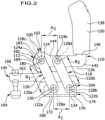
- eine Seitenansicht der Spannvorrichtung aus
Fig. 1 , in der Spannstellung der Spannvorrichtung, mit Blick auf die linke Seite der Spannvorrichtung; - Fig. 3
- eine Draufsicht auf die Spannvorrichtung aus den
Fig. 1 und2 von oben, in der Spannstellung der Spannvorrichtung; - Fig. 4
- eine Ansicht der Spannvorrichtung aus den
Fig. 1 bis 3 von vorne, in der Spannstellung der Spannvorrichtung; - Fig. 5
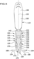
- eine Ansicht der Spannvorrichtung aus den
Fig. 1 bis 4 von hinten, in der Spannstellung der Spannvorrichtung; - Fig. 6
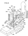
- eine perspektivische Darstellung der Spannvorrichtung aus den
Fig. 1 bis 5 , welche an einem Untergrund montiert ist, in einer Offenstellung der Spannvorrichtung; - Fig. 7
- eine Seitenansicht der Spannvorrichtung und des Untergrundes aus
Fig. 6 , in der Offenstellung der Spannvorrichtung; - Fig. 8
- eine perspektivische Darstellung der Spannvorrichtung und des Untergrundes aus den
Fig. 6 und7 in einer zwischen der Offenstellung der Spannstellung der Spannvorrichtung liegenden Zwischenstellung der Spannvorrichtung; - Fig. 9
- eine Seitenansicht der Spannvorrichtung und des Untergrundes der Spannvorrichtung aus
Fig. 8 , in der Zwischenstellung der Spannvorrichtung; - Fig. 10
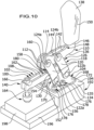
- eine perspektivische Darstellung der Spannvorrichtung und des Untergrundes aus den
Fig. 6 bis 9 , in der Spannstellung der Spannvorrichtung; - Fig. 11
- eine Seitenansicht der Spannvorrichtung und des Untergrundes aus
Fig. 10 , in der Spannstellung der Spannvorrichtung; - Fig. 12
- eine schematische Darstellung der ergonomisch verträglichen Winkelstellungen eines Ellenbogengelenks einer Bedienungsperson der Spannvorrichtung;
- Fig. 13
- eine schematische Darstellung der ergonomisch verträglichen Winkelstellungen eines Handgelenks einer Bedienungsperson der Spannvorrichtung; und
- Fig. 14
- eine schematische Darstellung der ergonomisch verträglichen Winkelstellungen eines Schultergelenks einer Bedienungsperson der Spannvorrichtung.
- Gleiche oder funktional äquivalente Elemente sind in allen Figuren mit denselben Bezugszeichen bezeichnet.
- Eine in den
Fig. 1 bis 11 dargestellte, als Ganzes mit 100 bezeichnete Spannvorrichtung ist im zeichnerisch dargestellten Ausführungsbeispiel als ein Schnellspanner 102 ausgebildet. - Die Spannvorrichtung 100 umfasst eine Basis 104, einen mittels eines Haltearmlagers 106 gelenkig mit der Basis 104 verbundenen Haltearm 108, einen Betätigungsarm 110 und zwei Spannstücke 112, die jeweils über ein Betätigungsarm-Spannstück-Lager 114 gelenkig mit dem Betätigungsarm 112 und über ein Haltearm-Spannstück-Lager 116 gelenkig mit dem Haltearm 108 verbunden sind.
- Ferner umfasst die Spannvorrichtung 100 zwei Paare 118 von jeweils zwei Parallelführungsgliedern 120, wobei jedes der Parallelführungsglieder 120 eines Paares 118 jeweils über ein Basis-Parallelführungsglied-Gelenk 122 gelenkig mit der Basis 104 und über ein Betätigungsarm-Parallelführungsglied-Gelenk 124 gelenkig mit dem Betätigungsarm 110 verbunden ist.
- Wie im Folgenden noch näher erläutert werden wird, bildet jedes Paar 118 von Parallelführungsgliedern 120 zusammen mit der Basis 104 und dem Betätigungsarm 110 jeweils eine Parallelführung 126 für den Betätigungsarm 110, durch welche der Betätigungsarm 110 bei der Überführung der Spannvorrichtung 100 von einer (beispielsweise in den
Fig. 6 und7 dargestellten) Offenstellung über eine (beispielsweise in denFig. 8 und9 dargestellte) Zwischenstellung in eine (beispielsweise in denFig. 1 bis 5 sowie 10 und 11 dargestellte) Spannstellung der Spannvorrichtung 100 seine Winkelausrichtung relativ zu der Basis 104 beibehält. - Wie beispielsweise aus
Fig. 2 zu ersehen ist, umfasst jedes Paar 118 von Parallelführungsgliedern 120 ein vorderes Parallelführungsglied 120a und ein hinteres Parallelführungsglied 120b, wobei das Basis-Parallelführungsglied-Gelenk 122a, mittels welchem das vordere Parallelführungsglied 120a um eine erste Gelenkachse 128a relativ zu der Basis 104 schwenkbar ist, näher an einem vorderen Ende 130 der Basis 104 angeordnet ist als das Basis-Parallelführungsglied-Gelenk 122b, mittels welchem das hintere Parallelführungsglied 120b um eine zweite Gelenkachse 128b relativ zu der Basis 104 schwenkbar ist. - Das vordere Parallelführungsglied 120a ist mittels des Betätigungsarm-Parallelführungsglied-Gelenks 124a um eine dritte Gelenkachse 128c relativ zu dem Betätigungsarm 110 schwenkbar.
- Das hintere Parallelführungsglied 120b ist mittels des Betätigungsarm-Parallelführungsglied-Gelenks 124b um eine vierte Gelenkachse 128d relativ zu dem Betätigungsarm 110 schwenkbar.
- Wie aus
Fig. 2 zu ersehen ist, ist der Abstand A1 zwischen der ersten Gelenkachse 128a und der zweiten Gelenkachse 128b gleich groß wie der Abstand A2 zwischen der dritten Gelenkachse 128c und der vierten Gelenkachse 128d. - Ferner ist der Abstand B1 zwischen der ersten Gelenkachse 128a und der dritten Gelenkachse 128c gleich groß wie der Abstand B2 zwischen der zweiten Gelenkachse 128b und der vierten Gelenkachse 128d.
- Die Schnittpunkte, an denen die Gelenkachsen 128a, 128b, 128c und 128d die Längsmittelebene 132 (siehe
Fig. 3 ) der Spannvorrichtung 100 schneiden, bilden somit die Ecken eines Parallelogramms. - Die Parallelführungsglieder 120 der Paare 118 von Parallelführungsgliedern 120 sind bezüglich der Längsmittelebene 132 der Spannvorrichtung 100 spiegelsymmetrisch zueinander ausgebildet und angeordnet.
- Die Längsmittelebene 132 der Spannvorrichtung 100 ist senkrecht zu einer Auflagefläche 134, mit welcher die Basis 104 an einem Untergrund 135 auflegbar ist, ausgerichtet.
- Die erste Gelenkachse 128a und die zweite Gelenkachse 128b liegen in einer Ebene, welche parallel zu der Auflagefläche 134 der Basis 104 ausgerichtet ist.
- Weil die Parallelführungsglieder 120a und 120b jedes Paars 118 von Parallelführungsgliedern 120 gleich lang und stets parallel zueinander ausgerichtet sind, liegen dann auch die dritte Gelenkachse 128c und die vierte Gelenkachse 128d stets in einer Ebene, welche parallel zu der Auflagefläche 134 der Basis 104 ausgerichtet ist.
- Hierdurch ist gewährleistet, dass der Betätigungsarm 110 in jeder Stellung der Spannvorrichtung 100 dieselbe Winkelausrichtung relativ zu der Auflagefläche 134 der Basis 104 aufweist.
- Insbesondere kann vorgesehen sein, dass ein der Basis 104 zugewandter Rand 136 des Betätigungsarms 110 parallel oder im Wesentlichen parallel zu der Auflagefläche 134 der Basis 104 ausgerichtet ist.
- Die beiden Spannstücke 112 der Spannvorrichtung 100 sind vorzugsweise zwischen den Parallelführungsgliedern 120 des links von dem Betätigungsarm 110 angeordneten Paares 118 von Parallelführungsgliedern 120 einerseits und den Parallelführungsgliedern 120 des rechts von dem Betätigungsarm 110 angeordneten Paares 118 von Parallelführungsgliedern 120 andererseits angeordnet.
- Dabei beziehen sich die Angaben "links von dem Betätigungsarm" und "rechts von dem Betätigungsarm" jeweils auf die Position links beziehungsweise rechts von der Längsmittelebene 132 der Spannvorrichtung 100, wobei die Blickrichtung von einem Betätigungsgriff 138 des Betätigungsarms 110 zum freien Ende 140 des Haltearms 108 gerichtet ist.
- Der Betätigungsarm 110 umfasst bei der zeichnerisch dargestellten Ausführungsform einer Spannvorrichtung 100 zwei Betätigungsarmwangen 142, welche vorzugsweise flächig aneinander anliegen.
- Jede Betätigungsarmwange 142 weist jeweils einen Lagerteil 144 und einen Griffteil 146 auf, die über eine Abkröpfung 148 miteinander verbunden sind.
- Die Griffteile 146 des Betätigungsarms 110 sind zumindest abschnittsweise von dem Betätigungsgriff 138 der Spannvorrichtung 100 umgeben.
- Der Betätigungsgriff 138 dient dazu, dass eine Bedienungsperson an demselben angreifen kann, um den Betätigungsarm 110 relativ zu der Basis 104 aus der in den
Fig. 6 und7 dargestellten Offenstellung über die in denFig. 8 und9 dargestellte Zwischenstellung bis in die in denFig. 10 und11 dargestellte Spannstellung der Spannvorrichtung 100 zu bewegen. - Der Betätigungsgriff 138 umfasst einen Betätigungsabschnitt 150, der in der Offenstellung, in der Zwischenstellung und in der Spannstellung der Spannvorrichtung 100 im Wesentlichen senkrecht zu der Auflagefläche 134 der Basis 104 ausgerichtet ist.
- Die beiden Spannstücke 112 der Spannvorrichtung 100 sind vorzugsweise zwischen den beiden Betätigungsarmwangen 142 des Betätigungsarms 110 angeordnet.
- Der Betätigungsarm 110 ist vorzugsweise zwischen den beiden Paaren 118 von Parallelführungsgliedern 120 angeordnet.
- Wie am besten aus den
Fig. 4 und5 zu ersehen ist, ist jedes der Parallelführungsglieder 120 vorzugsweise mit einer ersten Abkröpfung 152 versehen, welche einen Mittelteil 154 des Parallelführungsglieds 120 mit einem ersten Lagerabschnitt 156 des Parallelführungsglieds 120, an dem das Basis-Parallelführungsglied-Gelenk 122 angeordnet ist, verbindet, und mit einer zweiten Abkröpfung 158 versehen, welche den Mittelteil 154 des Parallelführungsglieds 120 mit einem zweiten Lagerabschnitt 160, an dem das Betätigungsarm-Parallelführungsglied-Gelenk 124 angeordnet ist, verbindet. - Der Haltearm 108 der Spannvorrichtung 100 umfasst zwei Haltearmschenkel 162, von denen einer links von der Längsmittelebene 132 der Spannvorrichtung 100 und der andere rechts von der Längsmittelebene 132 der Spannvorrichtung 100 angeordnet ist.
- Die beiden Haltearmschenkel 162 verlaufen im Wesentlichen parallel zueinander und sind dazu ausgebildet, ein Druckstück 164 zu tragen, mittels welchem der Haltearm 108 in der Spannstellung der Spannvorrichtung 100 eine Spannkraft auf ein mittels der Spannvorrichtung 100 an dem Untergrund 135 eingespanntes Werkstück 198 ausübt.
- Das Druckstück 164 ist in der Längsrichtung des Haltearms 108 verschiebbar an dem Haltearm 108 angeordnet und, beispielsweise mittels einer Mutter 166, in einer gewünschten Position relativ zu dem Haltearm 108 arretierbar.
- Die Basis 104 der Spannvorrichtung 100 ist bei der zeichnerisch dargestellten Ausführungsform der Spannvorrichtung 100 aus zwei Basiselementen 168 gebildet.
- Jedes der Basiselemente 168 umfasst einen Lagerteil 170 und einen Fußteil 172, die über eine Abkröpfung 174 miteinander verbunden sind.
- Jeder Fußteil 172 kann eine oder mehrere Befestigungsmittel-Durchtrittsöffnungen 176 aufweisen, durch welche sich (in den
Fig. 6 bis 11 dargestellte) Befestigungsmittel 178 hindurch erstrecken können, mit welchen die Basis 104 an dem Untergrund 135 festlegbar ist. - Die Lagerteile 170 der beiden Basiselemente 168 liegen vorzugsweise flächig aneinander an und tragen das Haltearmlager 106 sowie die Basis-Parallelführungsglied-Gelenke 122.
- Wie am besten aus den
Fig. 6 und7 zu ersehen ist, weist mindestens ein Spannstück 112 der Spannvorrichtung 100 einen Nocken 180 auf, der in der Offenstellung der Spannvorrichtung mit einer Nockenführungsausnehmung 182 des Betätigungsarms 110 in Eingriff steht. - Vorzugsweise ist vorgesehen, dass der Nocken 180 in der Offenstellung der Spannvorrichtung 100 an einem Endbereich 183 der Nockenführungsausnehmung 182 des Betätigungsarms 110 anliegt.
- Dabei bildet der Endbereich 183 der Nockenführungsausnehmung 182 des Betätigungsarms 110 einen Anschlag, welcher die Bewegung des Nockens 180 relativ zu dem Betätigungsarm 110 begrenzt und somit die Überführung der Spannvorrichtung 100 von der Spannstellung in die Offenstellung beendet.
- Der Nocken 180 gelangt bei der Überführung der Spannvorrichtung 100 von der Offenstellung in die Spannstellung aus der Nockenführungsausnehmung 182 des Betätigungsarms 110 heraus(siehe insbesondere die
Fig. 8 und9 ). - In der in den
Fig. 10 und11 dargestellten Spannstellung der Spannvorrichtung 100 steht der Nocken 180 des Spannstücks 112 mit einer Nockenführungsausnehmung 186 des Haltearms 108 in Eingriff. - Dabei bildet ein Rand 190 der Nockenführungsausnehmung 186 des Haltearms 108 einen Anschlag für den Nocken 180, welcher die Überführung der Spannvorrichtung 100 von der Offenstellung in die Spannstellung beendet.
- Der Haltearm 108, der Betätigungsarm 110, die Basis 104, die Spannstücke 112 und/oder die Parallelführungsglieder 120 können beispielsweise aus einem metallischen Material, insbesondere aus einem kaltgewalzten Flacherzeugnis, vorzugsweise aus einem Stahlmaterial oder einem Edelstahlmaterial, gebildet sein.
- Das metallische Material, insbesondere das kaltgewalzte Flacherzeugnis, vorzugsweise Stahlmaterial, kann verzinkt sein.
- Die vorstehend beschriebene Spannvorrichtung 100 funktioniert wie folgt:
In der in denFig. 6 und7 dargestellten Offenstellung der Spannvorrichtung 100 ist die Basis 104 der Spannvorrichtung 100 mittels der Befestigungsmittel 178 an dem Untergrund 135 festgelegt, welcher im dargestellten Ausführungsbeispiel als ein Sockel 192 ausgebildet ist, der eine Auflegefläche 194 für die Basis 104 und eine Einspannfläche 196 für das Auflegen des einzuspannenden Werkstücks 198 aufweist. - In dieser Offenstellung der Spannvorrichtung 100 liegt der Nocken 180 an dem Endbereich 183 der Nockenführungsausnehmung 182 des Betätigungsarms 110 an.
- Die Parallelführungsglieder 120 jedes Paares 118 von Parallelführungsgliedern 120 können in der Offenstellung der Spannvorrichtung 100 aneinander anliegen oder voneinander beabstandet sein.
- Wenn nun eine Bedienungsperson an dem Betätigungsgriff 138 der Spannvorrichtung 100 angreift, um die Spannvorrichtung 100 von der in den
Fig. 6 und7 dargestellten Offenstellung in die in denFig. 10 und11 dargestellte Spannstellung zu überführen, behält der Betätigungsgriff 138 seine Ausrichtung relativ zu der Auflagefläche 134 der Basis 104 der Spannvorrichtung 100 bei. - Dies wird dadurch erreicht, dass der Betätigungsarm 110 nicht direkt an der Basis 104 angelenkt ist, sondern indirekt über die Parallelführung 126, welche von den Parallelführungsgliedern 120 der beiden Paare 118 von Parallelführungsgliedern 120 gebildet wird.
- Die beiden Parallelführungsglieder 120 eines Paares 118 von Parallelführungsgliedern 120 sind stets parallel zueinander ausgerichtet.
- Dadurch, dass der Betätigungsgriff 138 seine Ausrichtung relativ zu der Auflagefläche 134 der Basis 104 nicht verändert, erfolgt die Überführung der Spannvorrichtung 100 von der Offenstellung in die Spannstellung durch eine Bewegung, bei welcher der Unterarm der Bedienungsperson aus dem Ellenbogengelenk heraus nach vorne bewegt wird, im Wesentlichen parallel zu der Auflagefläche 134 der Basis 104 und ohne Durchführung einer Abknickbewegung im Handgelenk der Bedienungsperson.
- Wie in
Fig. 12 dargestellt, bleibt die Hand der Bedienungsperson während der Überführung der Spannvorrichtung 100 von der Offenstellung in die Spannstellung immer in einer Position, welche einer Verlängerung des Unterarms der Bedienungsperson entspricht. - Bei der Betätigung der Spannvorrichtung 100 verändert der Unterarm seine Höhe nur minimal. Nur der Oberarm der Bedienungsperson verändert seinen Winkel relativ zum Rumpf der Bedienungsperson um maximal 20°, bezogen auf das Schultergelenk der Bedienungsperson, wie in
Fig. 14 dargestellt. - Dabei spricht man bei einem Schwenken des Oberarms nach vorne von einer Adduktion (AD in
Fig. 14 ) und bei einem Schwenken des Oberarms nach hinten von einer Abduktion (AB inFig. 14 ). - Der Unterarm der Bedienungsperson verbleibt hingegen während des gesamten Betätigungsvorgangs der Spannvorrichtung 100 stets in einem ergonomisch günstigen Winkelintervall einer Abweichung von minimal 60° und maximal 100° von der Vertikalen (Flexion F in
Fig. 12 ), bezogen auf das Ellenbogengelenk der Bedienungsperson. Innerhalb dieses Winkelintervalls können beliebig viele Betätigungsvorgänge durchgeführt werden, ohne dass eine Schädigung des Bewegungsapparats der Bedienungsperson und/oder eine Beeinträchtigung des Wohlbefindens der Bedienungsperson eintritt. - Ferner verbleibt, wie in
Fig. 13 dargestellt, während der gesamten Überführung der Spannvorrichtung 100 von der Offenstellung in die Spannstellung die Hand der Bedienungsperson innerhalb eines ergonomisch günstigen Winkelbereichs von -20° bis +25° Abweichung gegenüber der Längsrichtung des Unterarms der Bedienungsperson, bezogen auf das Handgelenk der Bedienungsperson. - Dabei spricht man bei einem Abknicken der Hand der Bedienungsperson nach oben von einer Extension (in
Fig. 13 mit E bezeichnet) und bei einer Abknickung der Hand der Bedienungsperson nach unten von einer Flexion (inFig. 13 mit F bezeichnet). - Bei der Betätigung der Spannvorrichtung 100 wird somit eine maximale Flexion von 20° und/oder eine maximale Extension von 25° nicht überschritten.
- Somit befindet sich die Stellung der Hand der Bedienungsperson bei der Betätigung der Spannvorrichtung 100 stets in einem ergonomisch günstigen Winkelbereich relativ zum Handgelenk, so dass die Spannvorrichtung 100 beliebig häufig von der Bedienungsperson betätigt werden kann, ohne dass hierdurch eine Schädigung des Bewegungsapparats der Bedienungsperson und/oder eine Beeinträchtigung des Wohlbefindens der Bedienungsperson verursacht werden würde.
- Bei der Überführung der Spannvorrichtung 100 von der in den
Fig. 6 und7 dargestellten Offenstellung in die in denFig. 8 und9 dargestellte Zwischenstellung gelangt der Nocken 180 aus der Nockenführungsausnehmung 182 des Betätigungsarms 110 heraus. - Wenn die Überführungsbewegung der Spannvorrichtung 100 von der Bedienungsperson fortgesetzt wird, gelangt der Nocken 180 in Eingriff mit der Nockenführungsausnehmung 186 des Haltearms 108, bis der Nocken 180 an dem Rand 190 der Nockenführungsausnehmung 186 des Haltearms 108 anliegt.
- Dann ist die in den
Fig. 10 und11 dargestellte Spannstellung der Spannvorrichtung 100 erreicht. - Die Überführung der Spannvorrichtung 100 von der Spannstellung in die Offenstellung erfolgt dadurch, dass die Bedienungsperson den Betätigungsgriff 138 in entgegengesetzter Richtung bewegt.
- Auch bei der Überführung der Spannvorrichtung 100 von der in den
Fig. 10 und11 dargestellten Spannstellung in die in denFig. 6 und7 dargestellte Offenstellung behält der Betätigungsgriff 138 seine Winkelausrichtung relativ zu der Auflagefläche 134 der Basis 104 der Spannvorrichtung 100 stets bei, so dass auch bei dieser Überführungsbewegung der Oberarm der Bedienungsperson stets in dem ergonomisch günstigen Bereich einer Adduktion von 0° bis maximal 20° verbleibt, der Unterarm der Bedienungsperson stets in dem ergonomisch günstigen Bereich einer Flexion des Ellenbogengelenks von minimal 60° und maximal 100° verbleibt und die Hand der Bedienungsperson stets in dem ergonomisch günstigen Bereich einer Extension des Handgelenks von höchstens 25° und einer Flexion des Handgelenks von höchstens 20° verbleibt.
Claims (13)
- Spannvorrichtung, insbesondere Schnellspanner (102), umfassend eine Basis (104),einen gelenkig mit der Basis (104) verbundenen Haltearm (108),einen Betätigungsarm (110) undmindestens ein gelenkig mit dem Betätigungsarm (110) und gelenkig mit dem Haltearm (108) verbundenes Spannstück (112),dadurch gekennzeichnet,dass die Spannvorrichtung (100) mindestens ein Paar (118) von Parallelführungsgliedern (120) umfasst,wobei jedes der Parallelführungsglieder (120) eines Paares (118) gelenkig mit der Basis (104) und gelenkig mit dem Betätigungsarm (110) verbunden ist und das Paar (118) von Parallelführungsgliedern (120), die Basis (104) und der Betätigungsarm (110) zusammen eine Parallelführung (126) für den Betätigungsarm (110) bilden, durch welche der Betätigungsarm (110) bei der Überführung der Spannvorrichtung (100) von einer Offenstellung der Spannvorrichtung (100) in eine Spannstellung der Spannvorrichtung (100) seine Winkelausrichtung relativ zu der Basis (104) beibehält.
- Spannvorrichtung nach Anspruch 1, dadurch gekennzeichnet, dass die Schnittpunkte, an denen die Gelenkachsen (128a, 128b, 128c, 128d) der Gelenke (122a, 122b, 124a, 124b), mittels welcher die Parallelführungsglieder (120) eines Paars (118) gelenkig mit der Basis (104) beziehungsweise gelenkig mit dem Betätigungsarm (110) verbunden sind, die Längsmittelebene (132) der Spannvorrichtung (100) schneiden, die Ecken eines Parallelogramms bilden.
- Spannvorrichtung nach einem der Ansprüche 1 oder 2, dadurch gekennzeichnet, dass der Betätigungsarm (110) gewinkelt ausgebildet ist.
- Spannvorrichtung nach einem der Ansprüche 1 bis 3, dadurch gekennzeichnet, dass mindestens ein Teil des Betätigungsarms (110) einen der Basis (104) zugewandten Rand (136) aufweist, welcher parallel zu einer Auflagefläche (134) der Basis (104) ausgerichtet ist, mit welcher die Basis (104) an einen Untergrund (135) auflegbar ist.
- Spannvorrichtung nach einem der Ansprüche 1 bis 4, dadurch gekennzeichnet, dass die Parallelführungsglieder (120) eines Paares (118) in der Offenstellung der Spannvorrichtung (100) aneinander anliegen.
- Spannvorrichtung nach einem der Ansprüche 1 bis 5, dadurch gekennzeichnet, dass der Betätigungsarm (110) mit einem Betätigungsgriff (138) versehen ist, welcher einen Betätigungsabschnitt (150) umfasst, der in der Offenstellung und in der Spannstellung der Spannvorrichtung (100) im Wesentlichen senkrecht zu einer Auflagefläche (134) der Basis (104) ausgerichtet ist, mit welcher die Basis (104) an einen Untergrund (135) auflegbar ist.
- Spannvorrichtung nach einem der Ansprüche 1 bis 6, dadurch gekennzeichnet, dass mindestens ein Spannstück (112) der Spannvorrichtung (100) einen Nocken (180) aufweist, der in der Offenstellung der Spannvorrichtung (100) mit einer Nockenführungsausnehmung (182) des Betätigungsarms (110) in Eingriff steht.
- Spannvorrichtung nach Anspruch 7, dadurch gekennzeichnet, dass der Nocken (180) in der Offenstellung der Spannvorrichtung (100) an einem Endbereich (183) der Nockenführungsausnehmung (182) des Betätigungsarms (110) anliegt.
- Spannvorrichtung nach einem der Ansprüche 1 bis 8, dadurch gekennzeichnet, dass mindestens ein Spannstück (112) der Spannvorrichtung (100) einen Nocken (180) aufweist, der in der Spannstellung der Spannvorrichtung (100) mit einer Nockenführungsausnehmung (186) des Haltearms (108) in Eingriff steht.
- Spannvorrichtung nach Anspruch 9, dadurch gekennzeichnet, dass der Nocken (180) in der Spannstellung der Spannvorrichtung (100) an einem Rand (190) der Nockenführungsausnehmung (186) des Haltearms (108) anliegt.
- Spannvorrichtung nach einem der Ansprüche 1 bis 10, dadurch gekennzeichnet, dass die Spannvorrichtung (100) zwei Paare (118) von Parallelführungsgliedern (120) umfasst,
- Spannvorrichtung nach Anspruch 11, dadurch gekennzeichnet, dass der Betätigungsarm (110) zwischen den beiden Paaren (118) von Parallelführungsgliedern (120) angeordnet ist.
- Spannvorrichtung nach einem der Ansprüche 1 bis 12, dadurch gekennzeichnet, dass der Betätigungsarm (110) zwei Betätigungsarmwangen (142) umfasst und das mindestens eine Spannstück (112) zwischen den beiden Betätigungsarmwangen (142) angeordnet ist.
Applications Claiming Priority (1)
| Application Number | Priority Date | Filing Date | Title |
|---|---|---|---|
| DE102021126798.6A DE102021126798A1 (de) | 2021-10-15 | 2021-10-15 | Spannvorrichtung |
Publications (2)
| Publication Number | Publication Date |
|---|---|
| EP4166277A1 EP4166277A1 (de) | 2023-04-19 |
| EP4166277B1 true EP4166277B1 (de) | 2024-10-02 |
Family
ID=83693075
Family Applications (1)
| Application Number | Title | Priority Date | Filing Date |
|---|---|---|---|
| EP22201352.6A Active EP4166277B1 (de) | 2021-10-15 | 2022-10-13 | Spannvorrichtung |
Country Status (2)
| Country | Link |
|---|---|
| EP (1) | EP4166277B1 (de) |
| DE (1) | DE102021126798A1 (de) |
Family Cites Families (4)
| Publication number | Priority date | Publication date | Assignee | Title |
|---|---|---|---|---|
| GB670218A (en) | 1949-10-06 | 1952-04-16 | C F Moore & Sons Ltd | Improvements relating to the work clamps of mitreing machines |
| GB778865A (en) | 1954-12-08 | 1957-07-10 | Speed Tools Ltd | Improvements in or relating to clamps |
| DE102014115432B4 (de) * | 2014-10-23 | 2019-05-09 | Andreas Maier Gmbh & Co. Kg | Spannvorrichtung mit lösbar gehaltenem Handgriff und Verfahren zum Einspannen eines Werkstücks mittels einer solchen Spannvorrichtung |
| DE102018121568A1 (de) | 2018-09-04 | 2020-03-05 | KUIPERS technologies GmbH | Greifvorrichtung zum Greifen von Metallblechen |
-
2021
- 2021-10-15 DE DE102021126798.6A patent/DE102021126798A1/de active Pending
-
2022
- 2022-10-13 EP EP22201352.6A patent/EP4166277B1/de active Active
Also Published As
| Publication number | Publication date |
|---|---|
| EP4166277A1 (de) | 2023-04-19 |
| DE102021126798A1 (de) | 2023-04-20 |
Similar Documents
| Publication | Publication Date | Title |
|---|---|---|
| DE69507991T2 (de) | Verriegelbare zange mit achsialer spannbewegung | |
| DE3877578T2 (de) | Anordnung zum halten einer hand. | |
| EP3837094B1 (de) | Vorrichtung zum unterstützen wenigstens eines armes eines benutzers | |
| DE60000575T2 (de) | Spannvorrichtung | |
| DE7902275U1 (de) | Vorrichtung zum selbsttaetigen transportieren von gegenstaenden | |
| EP0916446A1 (de) | Werkzeugmaschine zur 3-achsigen Bearbeitung von Werkstücken | |
| DE102019204393A1 (de) | Greiferelemente für Handhabungseinrichtungen | |
| DE3410515A1 (de) | Vorrichtung zur erzeugung von geradlinigen bewegungen bei handhabungsgeraeten | |
| DE102014109377A1 (de) | Vorrichtung zur Höhenverstellung eines Operationstischs | |
| EP0128330A1 (de) | Vorrichtung zur Erzeugung einer geradlinigen Bewegung bei Handhabungsgeräten | |
| DE69708095T2 (de) | Vorschubmechanismus für anschlussklemmenanbringvorrichtung | |
| EP4166277A1 (de) | Spannvorrichtung | |
| EP0684112A1 (de) | Spanntisch | |
| DE60005268T2 (de) | Heuwerbungsmaschine | |
| DE60223987T2 (de) | Stanzmaschine | |
| DE202009002066U1 (de) | Befestigungsbandzange | |
| DE1291098B (de) | Vorrichtung zum Aufbringen von Umleimern aus Furnier oder Kunststoff | |
| DE3042677A1 (de) | Schraubstock | |
| EP3511131A1 (de) | Vorrichtung und verfahren zum handhaben von brillengläsern sowie verfahren zur herstellung von brillengläsern | |
| EP1377395B1 (de) | Biegemaschine, insbesondere gesenk- oder abkantpresse, mit einem verstellbaren unterwerkzeug | |
| EP0074487B1 (de) | Spannvorrichtung | |
| AT526774B1 (de) | Pult zur Ablage eines Werkstücks aus Blech | |
| EP0144304A1 (de) | Vorrichtung zum Biegen von Blechen | |
| EP4417368A1 (de) | Spannvorrichtung | |
| DE202023002364U1 (de) | Arbeits- oder Sammelwerkzeug zur einarmigen Bedienung |
Legal Events
| Date | Code | Title | Description |
|---|---|---|---|
| PUAI | Public reference made under article 153(3) epc to a published international application that has entered the european phase |
Free format text: ORIGINAL CODE: 0009012 |
|
| STAA | Information on the status of an ep patent application or granted ep patent |
Free format text: STATUS: THE APPLICATION HAS BEEN PUBLISHED |
|
| AK | Designated contracting states |
Kind code of ref document: A1 Designated state(s): AL AT BE BG CH CY CZ DE DK EE ES FI FR GB GR HR HU IE IS IT LI LT LU LV MC ME MK MT NL NO PL PT RO RS SE SI SK SM TR |
|
| P01 | Opt-out of the competence of the unified patent court (upc) registered |
Effective date: 20230519 |
|
| STAA | Information on the status of an ep patent application or granted ep patent |
Free format text: STATUS: REQUEST FOR EXAMINATION WAS MADE |
|
| 17P | Request for examination filed |
Effective date: 20231005 |
|
| RBV | Designated contracting states (corrected) |
Designated state(s): AL AT BE BG CH CY CZ DE DK EE ES FI FR GB GR HR HU IE IS IT LI LT LU LV MC ME MK MT NL NO PL PT RO RS SE SI SK SM TR |
|
| GRAP | Despatch of communication of intention to grant a patent |
Free format text: ORIGINAL CODE: EPIDOSNIGR1 |
|
| STAA | Information on the status of an ep patent application or granted ep patent |
Free format text: STATUS: GRANT OF PATENT IS INTENDED |
|
| INTG | Intention to grant announced |
Effective date: 20240227 |
|
| GRAJ | Information related to disapproval of communication of intention to grant by the applicant or resumption of examination proceedings by the epo deleted |
Free format text: ORIGINAL CODE: EPIDOSDIGR1 |
|
| STAA | Information on the status of an ep patent application or granted ep patent |
Free format text: STATUS: REQUEST FOR EXAMINATION WAS MADE |
|
| GRAP | Despatch of communication of intention to grant a patent |
Free format text: ORIGINAL CODE: EPIDOSNIGR1 |
|
| STAA | Information on the status of an ep patent application or granted ep patent |
Free format text: STATUS: GRANT OF PATENT IS INTENDED |
|
| INTC | Intention to grant announced (deleted) | ||
| GRAS | Grant fee paid |
Free format text: ORIGINAL CODE: EPIDOSNIGR3 |
|
| INTG | Intention to grant announced |
Effective date: 20240725 |
|
| GRAA | (expected) grant |
Free format text: ORIGINAL CODE: 0009210 |
|
| STAA | Information on the status of an ep patent application or granted ep patent |
Free format text: STATUS: THE PATENT HAS BEEN GRANTED |
|
| AK | Designated contracting states |
Kind code of ref document: B1 Designated state(s): AL AT BE BG CH CY CZ DE DK EE ES FI FR GB GR HR HU IE IS IT LI LT LU LV MC ME MK MT NL NO PL PT RO RS SE SI SK SM TR |
|
| REG | Reference to a national code |
Ref country code: GB Ref legal event code: FG4D Free format text: NOT ENGLISH |
|
| REG | Reference to a national code |
Ref country code: CH Ref legal event code: EP |
|
| REG | Reference to a national code |
Ref country code: IE Ref legal event code: FG4D Free format text: LANGUAGE OF EP DOCUMENT: GERMAN |
|
| REG | Reference to a national code |
Ref country code: DE Ref legal event code: R096 Ref document number: 502022001806 Country of ref document: DE |
|
| REG | Reference to a national code |
Ref country code: LT Ref legal event code: MG9D |
|
| REG | Reference to a national code |
Ref country code: NL Ref legal event code: MP Effective date: 20241002 |
|
| PG25 | Lapsed in a contracting state [announced via postgrant information from national office to epo] |
Ref country code: NL Free format text: LAPSE BECAUSE OF FAILURE TO SUBMIT A TRANSLATION OF THE DESCRIPTION OR TO PAY THE FEE WITHIN THE PRESCRIBED TIME-LIMIT Effective date: 20241002 |
|
| PG25 | Lapsed in a contracting state [announced via postgrant information from national office to epo] |
Ref country code: NL Free format text: LAPSE BECAUSE OF FAILURE TO SUBMIT A TRANSLATION OF THE DESCRIPTION OR TO PAY THE FEE WITHIN THE PRESCRIBED TIME-LIMIT Effective date: 20241002 |
|
| PG25 | Lapsed in a contracting state [announced via postgrant information from national office to epo] |
Ref country code: IS Free format text: LAPSE BECAUSE OF FAILURE TO SUBMIT A TRANSLATION OF THE DESCRIPTION OR TO PAY THE FEE WITHIN THE PRESCRIBED TIME-LIMIT Effective date: 20250202 Ref country code: PT Free format text: LAPSE BECAUSE OF FAILURE TO SUBMIT A TRANSLATION OF THE DESCRIPTION OR TO PAY THE FEE WITHIN THE PRESCRIBED TIME-LIMIT Effective date: 20250203 Ref country code: HR Free format text: LAPSE BECAUSE OF FAILURE TO SUBMIT A TRANSLATION OF THE DESCRIPTION OR TO PAY THE FEE WITHIN THE PRESCRIBED TIME-LIMIT Effective date: 20241002 |
|
| PG25 | Lapsed in a contracting state [announced via postgrant information from national office to epo] |
Ref country code: FI Free format text: LAPSE BECAUSE OF FAILURE TO SUBMIT A TRANSLATION OF THE DESCRIPTION OR TO PAY THE FEE WITHIN THE PRESCRIBED TIME-LIMIT Effective date: 20241002 |
|
| PG25 | Lapsed in a contracting state [announced via postgrant information from national office to epo] |
Ref country code: BG Free format text: LAPSE BECAUSE OF FAILURE TO SUBMIT A TRANSLATION OF THE DESCRIPTION OR TO PAY THE FEE WITHIN THE PRESCRIBED TIME-LIMIT Effective date: 20241002 |
|
| PG25 | Lapsed in a contracting state [announced via postgrant information from national office to epo] |
Ref country code: ES Free format text: LAPSE BECAUSE OF FAILURE TO SUBMIT A TRANSLATION OF THE DESCRIPTION OR TO PAY THE FEE WITHIN THE PRESCRIBED TIME-LIMIT Effective date: 20241002 |
|
| PG25 | Lapsed in a contracting state [announced via postgrant information from national office to epo] |
Ref country code: NO Free format text: LAPSE BECAUSE OF FAILURE TO SUBMIT A TRANSLATION OF THE DESCRIPTION OR TO PAY THE FEE WITHIN THE PRESCRIBED TIME-LIMIT Effective date: 20250102 |
|
| PG25 | Lapsed in a contracting state [announced via postgrant information from national office to epo] |
Ref country code: GR Free format text: LAPSE BECAUSE OF FAILURE TO SUBMIT A TRANSLATION OF THE DESCRIPTION OR TO PAY THE FEE WITHIN THE PRESCRIBED TIME-LIMIT Effective date: 20250103 Ref country code: LV Free format text: LAPSE BECAUSE OF FAILURE TO SUBMIT A TRANSLATION OF THE DESCRIPTION OR TO PAY THE FEE WITHIN THE PRESCRIBED TIME-LIMIT Effective date: 20241002 |
|
| PG25 | Lapsed in a contracting state [announced via postgrant information from national office to epo] |
Ref country code: PL Free format text: LAPSE BECAUSE OF FAILURE TO SUBMIT A TRANSLATION OF THE DESCRIPTION OR TO PAY THE FEE WITHIN THE PRESCRIBED TIME-LIMIT Effective date: 20241002 Ref country code: CZ Free format text: LAPSE BECAUSE OF FAILURE TO SUBMIT A TRANSLATION OF THE DESCRIPTION OR TO PAY THE FEE WITHIN THE PRESCRIBED TIME-LIMIT Effective date: 20241002 |
|
| PG25 | Lapsed in a contracting state [announced via postgrant information from national office to epo] |
Ref country code: IT Free format text: LAPSE BECAUSE OF NON-PAYMENT OF DUE FEES Effective date: 20241013 |
|
| PG25 | Lapsed in a contracting state [announced via postgrant information from national office to epo] |
Ref country code: RS Free format text: LAPSE BECAUSE OF FAILURE TO SUBMIT A TRANSLATION OF THE DESCRIPTION OR TO PAY THE FEE WITHIN THE PRESCRIBED TIME-LIMIT Effective date: 20250102 |
|
| PG25 | Lapsed in a contracting state [announced via postgrant information from national office to epo] |
Ref country code: SM Free format text: LAPSE BECAUSE OF FAILURE TO SUBMIT A TRANSLATION OF THE DESCRIPTION OR TO PAY THE FEE WITHIN THE PRESCRIBED TIME-LIMIT Effective date: 20241002 |
|
| REG | Reference to a national code |
Ref country code: DE Ref legal event code: R097 Ref document number: 502022001806 Country of ref document: DE |
|
| PG25 | Lapsed in a contracting state [announced via postgrant information from national office to epo] |
Ref country code: MC Free format text: LAPSE BECAUSE OF FAILURE TO SUBMIT A TRANSLATION OF THE DESCRIPTION OR TO PAY THE FEE WITHIN THE PRESCRIBED TIME-LIMIT Effective date: 20241002 |
|
| PG25 | Lapsed in a contracting state [announced via postgrant information from national office to epo] |
Ref country code: DK Free format text: LAPSE BECAUSE OF FAILURE TO SUBMIT A TRANSLATION OF THE DESCRIPTION OR TO PAY THE FEE WITHIN THE PRESCRIBED TIME-LIMIT Effective date: 20241002 |
|
| PG25 | Lapsed in a contracting state [announced via postgrant information from national office to epo] |
Ref country code: BE Free format text: LAPSE BECAUSE OF NON-PAYMENT OF DUE FEES Effective date: 20241031 Ref country code: LU Free format text: LAPSE BECAUSE OF NON-PAYMENT OF DUE FEES Effective date: 20241013 |
|
| PG25 | Lapsed in a contracting state [announced via postgrant information from national office to epo] |
Ref country code: EE Free format text: LAPSE BECAUSE OF FAILURE TO SUBMIT A TRANSLATION OF THE DESCRIPTION OR TO PAY THE FEE WITHIN THE PRESCRIBED TIME-LIMIT Effective date: 20241002 |
|
| PG25 | Lapsed in a contracting state [announced via postgrant information from national office to epo] |
Ref country code: RO Free format text: LAPSE BECAUSE OF FAILURE TO SUBMIT A TRANSLATION OF THE DESCRIPTION OR TO PAY THE FEE WITHIN THE PRESCRIBED TIME-LIMIT Effective date: 20241002 |
|
| PG25 | Lapsed in a contracting state [announced via postgrant information from national office to epo] |
Ref country code: SK Free format text: LAPSE BECAUSE OF FAILURE TO SUBMIT A TRANSLATION OF THE DESCRIPTION OR TO PAY THE FEE WITHIN THE PRESCRIBED TIME-LIMIT Effective date: 20241002 |
|
| REG | Reference to a national code |
Ref country code: BE Ref legal event code: MM Effective date: 20241031 |
|
| PLBE | No opposition filed within time limit |
Free format text: ORIGINAL CODE: 0009261 |
|
| STAA | Information on the status of an ep patent application or granted ep patent |
Free format text: STATUS: NO OPPOSITION FILED WITHIN TIME LIMIT |
|
| PG25 | Lapsed in a contracting state [announced via postgrant information from national office to epo] |
Ref country code: SE Free format text: LAPSE BECAUSE OF FAILURE TO SUBMIT A TRANSLATION OF THE DESCRIPTION OR TO PAY THE FEE WITHIN THE PRESCRIBED TIME-LIMIT Effective date: 20241002 |
|
| 26N | No opposition filed |
Effective date: 20250703 |
|
| PG25 | Lapsed in a contracting state [announced via postgrant information from national office to epo] |
Ref country code: FR Free format text: LAPSE BECAUSE OF NON-PAYMENT OF DUE FEES Effective date: 20241202 |
|
| PG25 | Lapsed in a contracting state [announced via postgrant information from national office to epo] |
Ref country code: IE Free format text: LAPSE BECAUSE OF NON-PAYMENT OF DUE FEES Effective date: 20241013 |
|
| PGFP | Annual fee paid to national office [announced via postgrant information from national office to epo] |
Ref country code: DE Payment date: 20251023 Year of fee payment: 4 |
|
| PGFP | Annual fee paid to national office [announced via postgrant information from national office to epo] |
Ref country code: AT Payment date: 20260113 Year of fee payment: 4 |
|
| PG25 | Lapsed in a contracting state [announced via postgrant information from national office to epo] |
Ref country code: IT Free format text: LAPSE BECAUSE OF NON-PAYMENT OF DUE FEES Effective date: 20241013 |
|
| PGFP | Annual fee paid to national office [announced via postgrant information from national office to epo] |
Ref country code: IT Payment date: 20251031 Year of fee payment: 4 |
|
| PGRI | Patent reinstated in contracting state [announced from national office to epo] |
Ref country code: IT Effective date: 20241031 |
|
| PGFP | Annual fee paid to national office [announced via postgrant information from national office to epo] |
Ref country code: TR Payment date: 20251008 Year of fee payment: 4 |
|
| PG25 | Lapsed in a contracting state [announced via postgrant information from national office to epo] |
Ref country code: CY Free format text: LAPSE BECAUSE OF FAILURE TO SUBMIT A TRANSLATION OF THE DESCRIPTION OR TO PAY THE FEE WITHIN THE PRESCRIBED TIME-LIMIT; INVALID AB INITIO Effective date: 20221013 |
|
| PG25 | Lapsed in a contracting state [announced via postgrant information from national office to epo] |
Ref country code: HU Free format text: LAPSE BECAUSE OF FAILURE TO SUBMIT A TRANSLATION OF THE DESCRIPTION OR TO PAY THE FEE WITHIN THE PRESCRIBED TIME-LIMIT; INVALID AB INITIO Effective date: 20221013 |
|
| REG | Reference to a national code |
Ref country code: CH Ref legal event code: H13 Free format text: ST27 STATUS EVENT CODE: U-0-0-H10-H13 (AS PROVIDED BY THE NATIONAL OFFICE) Effective date: 20260527 |
|
| PG25 | Lapsed in a contracting state [announced via postgrant information from national office to epo] |
Ref country code: SI Free format text: LAPSE BECAUSE OF FAILURE TO SUBMIT A TRANSLATION OF THE DESCRIPTION OR TO PAY THE FEE WITHIN THE PRESCRIBED TIME-LIMIT Effective date: 20241002 |
|
| PG25 | Lapsed in a contracting state [announced via postgrant information from national office to epo] |
Ref country code: LT Free format text: LAPSE BECAUSE OF FAILURE TO SUBMIT A TRANSLATION OF THE DESCRIPTION OR TO PAY THE FEE WITHIN THE PRESCRIBED TIME-LIMIT Effective date: 20241002 |
|
| PG25 | Lapsed in a contracting state [announced via postgrant information from national office to epo] |
Ref country code: CH Free format text: LAPSE BECAUSE OF NON-PAYMENT OF DUE FEES Effective date: 20251031 |
|
| PG25 | Lapsed in a contracting state [announced via postgrant information from national office to epo] |
Ref country code: ME Free format text: LAPSE BECAUSE OF FAILURE TO SUBMIT A TRANSLATION OF THE DESCRIPTION OR TO PAY THE FEE WITHIN THE PRESCRIBED TIME-LIMIT Effective date: 20241002 |