EP4162972B1 - Intra-aortic balloon apparatus, assist devices, for improving flow, counterpulsation, and haemodynamics - Google Patents
Intra-aortic balloon apparatus, assist devices, for improving flow, counterpulsation, and haemodynamics Download PDFInfo
- Publication number
- EP4162972B1 EP4162972B1 EP22208142.4A EP22208142A EP4162972B1 EP 4162972 B1 EP4162972 B1 EP 4162972B1 EP 22208142 A EP22208142 A EP 22208142A EP 4162972 B1 EP4162972 B1 EP 4162972B1
- Authority
- EP
- European Patent Office
- Prior art keywords
- balloon
- expandable frame
- distal
- proximal
- flow
- Prior art date
- Legal status (The legal status is an assumption and is not a legal conclusion. Google has not performed a legal analysis and makes no representation as to the accuracy of the status listed.)
- Active
Links
Images


Classifications
-
- A—HUMAN NECESSITIES
- A61—MEDICAL OR VETERINARY SCIENCE; HYGIENE
- A61M—DEVICES FOR INTRODUCING MEDIA INTO, OR ONTO, THE BODY; DEVICES FOR TRANSDUCING BODY MEDIA OR FOR TAKING MEDIA FROM THE BODY; DEVICES FOR PRODUCING OR ENDING SLEEP OR STUPOR
- A61M60/00—Blood pumps; Devices for mechanical circulatory actuation; Balloon pumps for circulatory assistance
- A61M60/80—Constructional details other than related to driving
- A61M60/855—Constructional details other than related to driving of implantable pumps or pumping devices
- A61M60/89—Valves
- A61M60/894—Passive valves, i.e. valves actuated by the blood
- A61M60/896—Passive valves, i.e. valves actuated by the blood having flexible or resilient parts, e.g. flap valves
-
- A—HUMAN NECESSITIES
- A61—MEDICAL OR VETERINARY SCIENCE; HYGIENE
- A61M—DEVICES FOR INTRODUCING MEDIA INTO, OR ONTO, THE BODY; DEVICES FOR TRANSDUCING BODY MEDIA OR FOR TAKING MEDIA FROM THE BODY; DEVICES FOR PRODUCING OR ENDING SLEEP OR STUPOR
- A61M60/00—Blood pumps; Devices for mechanical circulatory actuation; Balloon pumps for circulatory assistance
- A61M60/10—Location thereof with respect to the patient's body
- A61M60/122—Implantable pumps or pumping devices, i.e. the blood being pumped inside the patient's body
- A61M60/126—Implantable pumps or pumping devices, i.e. the blood being pumped inside the patient's body implantable via, into, inside, in line, branching on, or around a blood vessel
- A61M60/13—Implantable pumps or pumping devices, i.e. the blood being pumped inside the patient's body implantable via, into, inside, in line, branching on, or around a blood vessel by means of a catheter allowing explantation, e.g. catheter pumps temporarily introduced via the vascular system
-
- A—HUMAN NECESSITIES
- A61—MEDICAL OR VETERINARY SCIENCE; HYGIENE
- A61M—DEVICES FOR INTRODUCING MEDIA INTO, OR ONTO, THE BODY; DEVICES FOR TRANSDUCING BODY MEDIA OR FOR TAKING MEDIA FROM THE BODY; DEVICES FOR PRODUCING OR ENDING SLEEP OR STUPOR
- A61M60/00—Blood pumps; Devices for mechanical circulatory actuation; Balloon pumps for circulatory assistance
- A61M60/10—Location thereof with respect to the patient's body
- A61M60/122—Implantable pumps or pumping devices, i.e. the blood being pumped inside the patient's body
- A61M60/126—Implantable pumps or pumping devices, i.e. the blood being pumped inside the patient's body implantable via, into, inside, in line, branching on, or around a blood vessel
- A61M60/135—Implantable pumps or pumping devices, i.e. the blood being pumped inside the patient's body implantable via, into, inside, in line, branching on, or around a blood vessel inside a blood vessel, e.g. using grafting
- A61M60/139—Implantable pumps or pumping devices, i.e. the blood being pumped inside the patient's body implantable via, into, inside, in line, branching on, or around a blood vessel inside a blood vessel, e.g. using grafting inside the aorta, e.g. intra-aortic balloon pumps
-
- A—HUMAN NECESSITIES
- A61—MEDICAL OR VETERINARY SCIENCE; HYGIENE
- A61M—DEVICES FOR INTRODUCING MEDIA INTO, OR ONTO, THE BODY; DEVICES FOR TRANSDUCING BODY MEDIA OR FOR TAKING MEDIA FROM THE BODY; DEVICES FOR PRODUCING OR ENDING SLEEP OR STUPOR
- A61M60/00—Blood pumps; Devices for mechanical circulatory actuation; Balloon pumps for circulatory assistance
- A61M60/20—Type thereof
- A61M60/295—Balloon pumps for circulatory assistance
-
- A—HUMAN NECESSITIES
- A61—MEDICAL OR VETERINARY SCIENCE; HYGIENE
- A61M—DEVICES FOR INTRODUCING MEDIA INTO, OR ONTO, THE BODY; DEVICES FOR TRANSDUCING BODY MEDIA OR FOR TAKING MEDIA FROM THE BODY; DEVICES FOR PRODUCING OR ENDING SLEEP OR STUPOR
- A61M60/00—Blood pumps; Devices for mechanical circulatory actuation; Balloon pumps for circulatory assistance
- A61M60/30—Medical purposes thereof other than the enhancement of the cardiac output
- A61M60/31—Medical purposes thereof other than the enhancement of the cardiac output for enhancement of in vivo organ perfusion, e.g. retroperfusion
- A61M60/33—Medical purposes thereof other than the enhancement of the cardiac output for enhancement of in vivo organ perfusion, e.g. retroperfusion of kidneys
-
- A—HUMAN NECESSITIES
- A61—MEDICAL OR VETERINARY SCIENCE; HYGIENE
- A61M—DEVICES FOR INTRODUCING MEDIA INTO, OR ONTO, THE BODY; DEVICES FOR TRANSDUCING BODY MEDIA OR FOR TAKING MEDIA FROM THE BODY; DEVICES FOR PRODUCING OR ENDING SLEEP OR STUPOR
- A61M60/00—Blood pumps; Devices for mechanical circulatory actuation; Balloon pumps for circulatory assistance
- A61M60/40—Details relating to driving
- A61M60/497—Details relating to driving for balloon pumps for circulatory assistance
-
- A—HUMAN NECESSITIES
- A61—MEDICAL OR VETERINARY SCIENCE; HYGIENE
- A61M—DEVICES FOR INTRODUCING MEDIA INTO, OR ONTO, THE BODY; DEVICES FOR TRANSDUCING BODY MEDIA OR FOR TAKING MEDIA FROM THE BODY; DEVICES FOR PRODUCING OR ENDING SLEEP OR STUPOR
- A61M60/00—Blood pumps; Devices for mechanical circulatory actuation; Balloon pumps for circulatory assistance
- A61M60/80—Constructional details other than related to driving
- A61M60/841—Constructional details other than related to driving of balloon pumps for circulatory assistance
- A61M60/843—Balloon aspects, e.g. shapes or materials
-
- A—HUMAN NECESSITIES
- A61—MEDICAL OR VETERINARY SCIENCE; HYGIENE
- A61M—DEVICES FOR INTRODUCING MEDIA INTO, OR ONTO, THE BODY; DEVICES FOR TRANSDUCING BODY MEDIA OR FOR TAKING MEDIA FROM THE BODY; DEVICES FOR PRODUCING OR ENDING SLEEP OR STUPOR
- A61M60/00—Blood pumps; Devices for mechanical circulatory actuation; Balloon pumps for circulatory assistance
- A61M60/80—Constructional details other than related to driving
- A61M60/855—Constructional details other than related to driving of implantable pumps or pumping devices
- A61M60/861—Connections or anchorings for connecting or anchoring pumps or pumping devices to parts of the patient's body
-
- A—HUMAN NECESSITIES
- A61—MEDICAL OR VETERINARY SCIENCE; HYGIENE
- A61M—DEVICES FOR INTRODUCING MEDIA INTO, OR ONTO, THE BODY; DEVICES FOR TRANSDUCING BODY MEDIA OR FOR TAKING MEDIA FROM THE BODY; DEVICES FOR PRODUCING OR ENDING SLEEP OR STUPOR
- A61M60/00—Blood pumps; Devices for mechanical circulatory actuation; Balloon pumps for circulatory assistance
- A61M60/80—Constructional details other than related to driving
- A61M60/855—Constructional details other than related to driving of implantable pumps or pumping devices
- A61M60/865—Devices for guiding or inserting pumps or pumping devices into the patient's body
-
- A—HUMAN NECESSITIES
- A61—MEDICAL OR VETERINARY SCIENCE; HYGIENE
- A61M—DEVICES FOR INTRODUCING MEDIA INTO, OR ONTO, THE BODY; DEVICES FOR TRANSDUCING BODY MEDIA OR FOR TAKING MEDIA FROM THE BODY; DEVICES FOR PRODUCING OR ENDING SLEEP OR STUPOR
- A61M60/00—Blood pumps; Devices for mechanical circulatory actuation; Balloon pumps for circulatory assistance
- A61M60/10—Location thereof with respect to the patient's body
- A61M60/122—Implantable pumps or pumping devices, i.e. the blood being pumped inside the patient's body
- A61M60/126—Implantable pumps or pumping devices, i.e. the blood being pumped inside the patient's body implantable via, into, inside, in line, branching on, or around a blood vessel
- A61M60/148—Implantable pumps or pumping devices, i.e. the blood being pumped inside the patient's body implantable via, into, inside, in line, branching on, or around a blood vessel in line with a blood vessel using resection or like techniques, e.g. permanent endovascular heart assist devices
-
- A—HUMAN NECESSITIES
- A61—MEDICAL OR VETERINARY SCIENCE; HYGIENE
- A61M—DEVICES FOR INTRODUCING MEDIA INTO, OR ONTO, THE BODY; DEVICES FOR TRANSDUCING BODY MEDIA OR FOR TAKING MEDIA FROM THE BODY; DEVICES FOR PRODUCING OR ENDING SLEEP OR STUPOR
- A61M60/00—Blood pumps; Devices for mechanical circulatory actuation; Balloon pumps for circulatory assistance
- A61M60/20—Type thereof
- A61M60/247—Positive displacement blood pumps
- A61M60/253—Positive displacement blood pumps including a displacement member directly acting on the blood
- A61M60/268—Positive displacement blood pumps including a displacement member directly acting on the blood the displacement member being flexible, e.g. membranes, diaphragms or bladders
- A61M60/274—Positive displacement blood pumps including a displacement member directly acting on the blood the displacement member being flexible, e.g. membranes, diaphragms or bladders the inlet and outlet being the same, e.g. para-aortic counter-pulsation blood pumps
Definitions
- the catheter tube has a distal end joined via a traditional technique (e.g. welded, molded or adhered with adhesive, or any other method suitable for joining the edges of two plastic portions) to the balloon's proximal end, and a proximal end extending freely outside of the body, connected to an external balloon pump and receiving positive and negative pressure pulses for the balloon's inflation and deflation.
- the catheter tube is preferably made of polyethylene, although any other biocompatible material used for medical tubes, i.e., PVC, urethanes, polypropylene, polycarbonate, silicone, ABS, Pebax TM , Hytrel TM , C-Flex TM , Texin TM , Tecoflex TM can be used. Alternatively a superelastic metal alloy, such as nitinol, may be used.
- the catheter tube may have a single lumen (operating one balloon), or multiple lumens (based upon the number of balloons and pressure sensors used).
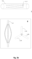
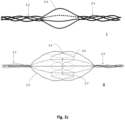
- FIG. 2a depicts exemplary lateral and superior views of slit tubes having 3 (ii), 4 (iii) and 6 (iv) radially expandable members 1.31, 1.32, 1.33, 1.34, etc.
- Different heat-set tooling can produce any kind of three dimensional structure (e.g., Fig. 2 sub i ), ellipsoidal, ellipsoid hyperboloid, ovoid, trapezoid, spherical, disciform or any combination thereof, depending on the interior of the surface that needs to be conformed with.
- ellipsoid paraboloidal is particularly useful in cases where a stent member needs to conform to a central smaller diameter.
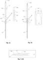
- Figs. 1a through 1o show embodiments illustrative of the invention in which frames 1.3 are expanded in conjunction with deployment of a pumping balloon 1.1 carried by the balloon catheter 1.20.
- the frames will be described in relation to the balloon 1.1 as proximal if they are positioned more toward the catheter end extending freely outside of the body, and distal if they are positioned more toward the catheter end positioned within the circulation lumen. They are further divided to upper (more distal) and lower (more proximal), when more than one proximal or distal stent members are described.
- a proximal expandable frame 1.3 is delivered in a collapsed state, mounted on an elongated shaft 1.2.
- the expandable frame 1.3 comprises the distal portion of the shaft, which is advanced through the balloon's insertion site and operated from out of the body, surrounding the balloon catheter 1.20.
- the shaft is inserted separately to the balloon and pushed against a stopping element 1.86 that surrounds the balloon catheter 1.20; the expandable frame 1.3 is pretreated, heat set, and biased to obtain an ellipsoid configuration upon expansion, and thus longitudinal sliding 1.4 is transformed to radial expansion ( Fig. 1b ).
- the applied force/longitudinal shortening (F/dL) relationship curve may be continuously monitored using an electronic interface connected to an external control handle and a potentiometer applying the force to the proximal portion for the sliding of the shaft 1.2.
- the interface may display continuously in a graphical or numerical manner the applied force for a given longitudinal motion, and the zero point may be the moment the shaft 1.2 reaches the stopping element 1.86.
- the inventors have determined that there is a curve point where more force is needed to achieve more expansion and this is may be different for each stent member size and circulation lumen.
- An electronic automatic system may be used to apply longitudinal force and detect substantial deviation from the relationship curve indicating contact between the expandable frame and the walls of the vessel or cavity, allowing expansion up to contact or a maximum desired diameter.
- gradation markers and indices reflecting the actual diameter of the stent member may be printed upon the balloon catheter portion 1.20, where the proximal portion of the shaft is rested outside of the body, so that the operator may be aware of the expanded diameter.
- manual opening up to a predetermined diameter may be used in cases where the circulation lumen wall is able to sustain small expansion force without significant risk for perforation.
- this second lumen is commonly referred to as "pressure line” or “pressure sensor line” or “pressure tube”.
- this second lumen is also routinely used to thread a guiding wire.
- a lumen like a pressure-sensor lumen is still provided to support the balloon 1.1 along its length and prevent longitudinal folding of the balloon during inflation/deflation, as well as to provide a path for a guiding wire.
- both lumens as intra-balloon lumens 1.22, where pressure sensing may or may not be provided in some implementations of the apparatus.
- Fig. 1 sub ii corresponds to the addition of a sleeve tube 1.87 that may be used to keep the expandable frame restrained to reduce the device's profile and facilitate insertion.
- the balloon catheter 1.20 incorporates a stopping element 1.79 positioned within the expandable frame 1.3 so that it becomes abutted against the proximal shaft portion of the expandable frame 1.3 to prevent excessive travel thereof and limit expansion to a predetermined diameter.
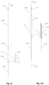
- the expandable frame 1.3 Two expansion methods of the expandable frame 1.3, an induced-one and a self-expanding one, will be described.
- the elongate hollow shaft 1.45 integrating the expandable frame 1.3
- a stopping element 1.46 By stopping element in this case is meant a widened end of the guiding wire 1.47 or an end cap joined to the end of the guiding wire.
- the expandable frame 1.3 is pretreated and heat set, to obtain a biased ellipsoid configuration upon expansion.
- the inner diameter of the expandable frame 1.3 is less than the outer diameter of the stopping element 1.46.
- the shaft 1.45 is advanced through the balloon's insertion site, surrounding the guiding wire 1.47, and operated from outside of the body.
- a sleeve tube may be used to facilitate insertion of the shaft 1.45 and to restrain the integrated expandable frame 1.3 from deploying.
- the stopping element 1.46 Upon reaching the stopping element 1.46, further longitudinal sliding toward the stopping element is transformed to radial expansion of the expandable frame 1.3.
- the widened end of the guiding wire 1.47 and the elongate hollow shaft 1.45 may be fixed together at their distal ends and advanced to the operation site as a unit.
- Preferred joint methods are welding, molding, crimping, adherence with glue, or any other method suitable for joining the edges of two plastic portions or plastic/metal portions, or metal portions.
- the hollow shaft 1.45 operated from outside the body, slides freely over the guiding wire 1.47 and the expandable frame 1.3 expands when pushed against the fixed-together ends.
- the expandable frame 1.3 on the elongated hollow shaft is pretreated to deploy to a predetermined desired diameter.
- the distal ends of the hollow shaft 1.45 and guiding wire 1.47 may slide freely to be fixed together.
- An outer sleeve tube 1.87 like that shown in Fig. 1 sub ii, may be manipulated for delivery and deployment control.
- the outer sleeve tube 1.87 has an inner diameter larger than the outer diameter of the expandable frame 1.3 and elongate shaft 1.45 (substituting for the balloon catheter 1.20 of the cited figure).
- the elongate shaft and sleeve tube are hollow structures comprising of a reasonably flexible biocompatible plastic material or a metal material, preferably superelastic Nitinol, such as Nitinol alloy S.
- plastic materials are biocompatible polypropylene, polyethylene, PVC, silicone, polyurethane, polystyrene and combinations thereof.
- the intra-balloon lumen 1.22 has an inner diameter larger than the outer diameter of the expandable frame 1.3 and elongate shaft 1.45, during removal of the balloon apparatus the intra-balloon lumen may be used as a sleeve tube.
- the stopping element 1.46 may again be a widened end of the guiding wire 1.47 or an end cap joined to the end of the guiding wire. In either case, for either of the above methods, the stopping element 1.46 needs to have a sufficiently small diameter to threat through a needle or obturator during percutaneous insertion.
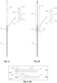
- Fig 1k depicts an exemplary combination of distal and proximal expandable frames 1.3.
- Each one can be separately controllable as described above, being self-expandable or induced-expandable.
- the proximal expandable frame 1.3c is integrated in a hollow shaft 1.2 and forced to expand due to the longitudinal sliding 1.4 of the shaft with respect to the balloon catheter 1.20.
- the distal expandable frame 1.3d is in an initial collapsed state and forced to expand due to longitudinal pulling 1.42 of the operating member 1.18 or guiding wire 1.47, in accordance with the alternatives described above.
- the distal expandable frame 1.3d is fixed on the balloon's tip 1.23 and traction of the member or wire engages the respective stopping element 1.17 or 1.46 with the distal shaft portion of the expandable frame, forcing it to expand.
- Figs. 1n and 1o show a preferred controlled expansion combination of two distal expandable frames 1.3a and 1.3b and a proximal expandable frame 1.3c mounted upon a balloon apparatus on either side of a pumping balloon 1.1.
- All stent members 1.3a, 1.3b and 1.3c comprise self-expanding frames predetermined to expand up to a desired diameter. They are delivered in a collapsed state, Fig 1n , and they are restrained by a sleeve tube 1.51.
- the expandable frames have their proximal portions 1.81 joined to a balloon tip portion 1.24, whereas their distal ends are free to slide along the balloon tip portion 1.24.
- An important advantage of the system is that can be used to increase the blood pressure and flow in any part of the circulation during CPB (celiac arteries, carotids, renal arteries, etc.). In this case it is used to augment pressure and flow in the renal arteries 4.6 through operation of a proximal, passive, and distally-opening unidirectional valve, preventing upstream flow (opposite to CPB flow) as shown.
- the valve 4.5 opens and closes periodically in conjunction with the balloon pumping.
- the valve opens ( Fig. 4b ) when downstream flow originating from the CPB forces the leaflets 4.5a, 4.5b, etc. to open, and vice versa closes ( Fig 4a ) when pressure and upstream flow originating from the balloon's pumping exceeds the blood pressure 4.7 on the proximal side of the valve.
- the exact positioning of the expandable frame 4.2 in relation with the renal arteries 4.6 remains to be ascertained. However it is anticipated that: the best position of the expandable frame 4.5 will be 4-5 cm upstream from the renal arteries, and the best position for the distal end of the balloon is likely 1-2 cm below the renal arteries.. These help both to minimize retrograde flow from the renal arteries during the balloon's deflation, and to optimize blood pooling and flow towards the renal arteries without balloon itself impeding the flow.
- this application is expected to reduce dramatically the size of the balloon 4.1 and subsequently the size of the balloon catheter 4.9 needed to achieve the same pressure effect in the renal arteries in comparison with the current conventional IAB.
- Figs. 5a and 5b depict another exemplary or preferred embodiment. It integrates an additional, distal expandable frame 5.4 for better centering and fixing of a 'renal' IAB.
- the distal expandable frame 5.4 when fully expanded, can be used solely to space the balloon 5.1 in the center of the abdominal aorta 5.8, thereby avoiding balloon-to-wall contact.
- the expandable frame 5.3 is shown to integrate occlusion device 5.14, such as a membrane attached to the inner surface 5.13, or any portion thereof, of the frame members.
- distal expandable frame 5.4 could combine with any other occlusion device.
- An inflatable occlusion balloon of a diameter between 0.5-2.5 cm, residing within, below, or above the distal expandable frame 5.4, would occlude partially the downstream flow and serve equally the same purposes of an occlusion device, thereby localizing and maximizing the pressure and flow effect between this valve/balloon and the proximal expandable frame 5.2.
- This same apparatus in a smaller version, is particularly useful in the cases where a cerebral artery is ruptured in the course of a bleeding stroke.
- selective lateral branch augmentation perfusion analogous to selective perfusion of the renal arteries 5.6, is likely warranted to compensate the lack of perfusion via collateral vascular routes.
- the device is fed collapsed and percutaneously inserted to a position upstream of the bleeding area and the occlusion device 5.14 is deployed.
- the pumping balloon 5.1 starts to operate in non-gating mode.
- the upstream (as shown, distal) check valve 5.5 opens and vacuums blood into the lumen surrounding the pumping balloon.
- the upstream check valve 5.5 closes and the blood is ejected towards the lateral branch 5.6a.
- the rate and volume of the balloon inflation cycles determine the desired output.
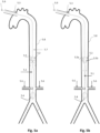
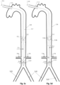
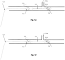
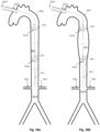
- Figs. 7a and 7b , 8a and 8b , and 9a and 9b depict other exemplary or preferred embodiments where the entry site of the IAB is the traditional femoral access 7.11, 8.11, and 9.11, respectively, and the IAB is gated with the aortic valve 7.12, 8.12, and 9.12 respectively, in counterpulsation mode.
- the current invention can be used to augment pressure and blood flow in any branches of the lower (abdominal) and upper (thoracic) aorta, an exemplary emphasis will continue to be given to the renal arteries and lower aorta where they originate.
- Fig. 7a the aortic valve 7. 12 is closed, the pumping balloon 7.1 is inflated, and check valve 7.5 is closed, thereby 'isolating' the pressure augmentation effect in the lower aorta 7.10 below the valve, where the renal arteries 7.6 originate.
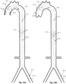
- the IAB is combined with a proximal expandable frame 9.2 including a occlusion device 9.14 and a distal expandable frame 9.4 including a distally-opening check valve 9.5.
- the occlusion device may comprise a membrane 9.14 attached to the inner surface 9.13 of the expandable frame 9.2.
- a similar occlusion device could be an inflated occlusion balloon, positioned at the same level.
- the occlusion device 9.14 provides a twofold advantage: 1. a partial downstream flow obstruction which augments retrograde flow to the renal arteries 9.6 and 2. a prevention of retrograde flow from more peripheral sites 9.15 which reduces 'steal phenomenon' from the periphery thereby increasing blood flow in the lower aorta 9.10 between the respective expandable frames 9.2 and 9.4.
- Figs. 10a and 10b illustrate an exemplary IAB including a pumping balloon 10.1 combined with a single expandable frame 10.2 placed at its proximal end.
- This proximal expandable frame 10.2 shown in an expanded state, is carrying a proximally-opening unidirectional check valve 10.5.
- semi-lunar leaflets 10.5a and 10.5b originating from an annular portion of the expandable frame 10.2 are depicted.
- the leaflets of the check valve are thin, supple and move easily from the completely open position (when the pumping balloon 10.1 inflates) to the closed position (when the pumping balloon 10.1 deflates).
- the aorta 10.8, the aortic valve 10.12, and renal 10.6 and common iliac/femoral arteries 10.11 are shown.
- the exact positioning of the expandable frame 10.2 in relation with the renal arteries 10.6 remains to be ascertained. However it is anticipated that the best position of the expandable frame 10.2 will be 4-5 cm just above the renal arteries. This helps to prevent retrograde flow from the renal arteries during the balloon's deflation, and yet allow downstream flow towards the renal arteries 10.6 without impeding the flow.
- the doctor may evaluate the exact positioning by looking at an image produced by an angiogram with contrast injection performed after the insertion of the system. Ideally, contrast agent injected below the check valve 10.5 of the expandable frame 10.2, shouldn't reach the upper aorta 10.7 above the check valve 10.5.
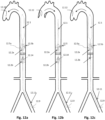
- Figs. 11a and 11b and 12a to 12c illustrate two other exemplary or preferred embodiments related to the apparatus shown in Figs. 10a and 10b , incorporating a femorally inserted 11.11, 12.11 apparatus, upper proximal expandable frames 11.2a and 12.2a, respectively, having proximally-opening check valves 11.5 and 12.5, respectively, and pumping balloons 11.1 and 12.1, respectively, operating in counterpulsation mode, but additionally lower proximal expandable frames 11.2b and 12.2b, respectively, which function as selectively deployable blocking elements.
- Figs. 11a, 11b , 12a, and 12b show the deployed configurations
- Fig. 12c shows the collapsed, 'normal state' configuration.
- the former embodiment, 11.2b integrates a 'complete' blocking element, i.e. a distally-opening unidirectional check valve 11.5, while the letter integrates a occlusion device 12.14 providing partial blocking, such as a continuous membrane mounted thereupon or an inflatable occlusive balloon.
- the lower proximal expandable frame 11.2b, 12.2b is deployed to at least partially block the downstream flow (at 11.9, 12.10 ). That way the limited cardiac output and the pressure generated from the heart is used momentarily to perfuse the upper part of the body, the brain and the heart, until cardiac output is restored.
- Figs. 13a and 13b depict a preferred embodiment for increasing aortic pressure in a specific compartment of the aorta 13.8, with the embodiment incorporating a pumping balloon 13.1 fluidically connected to more proximal bi-directional valve 13.25, such as an occlusive balloon.
- Fluidically connected bi-directional valves specifically assist balloons to IAB
- IAB Fluidically connected bi-directional valves
- this pressure split relies on the proximity of the assisted balloon to the vessel wall. It is easily understood by those familiar with the art that close proximity predisposes to aortic wall trauma. Subsequently there is a fine balance between pressure effect compartmentalization and aortic wall trauma, making it apparently impossible to achieve both.
- the embodiment shown in Figs. 13a and 13b circumvents the aforementioned limitations by integrating a proximal expandable frame 13.2, including a distally-opening, unidirectional check valve, proximate the bi-directional valve 13.25 and
- This proximal expandable frame 13.2 conforms precisely the interior of the Aorta and centralizes the bi-directional valve balloon 13.25 within the aorta 13.8.
- the check valve 13.5 on the interposed expandable frame 13.2 closes and prevents retrograde flow.
- the check valve 13.5 on the interposed expandable frame 13.2 would normally open.
- the close proximity of the bi-directional valve balloon 13.25 to the proximal side of the check valve 13.5 compared to the pumping balloon 13.1, creates locally higher pressure which either prevents or delays opening of the interposed check valve.
- a variety of bi-directional valve balloon volumes and distance relationships can be used in order to predetermine the interposed check valve's opening delay. Both the distance and balloon volume determine local pressure augmentation and check valve closure delay/opening timing. It is important to understand that the proximal bi-directional valve 13.25 is an alternative to the lower proximal expandable frame 12.2b shown in Figs 12a and 12b .
- Figs. 14a and 14b , 15a and 15b , and 16a and 16b show exemplary embodiments particularly useful in enforcing pressure and flow in peripheral parts of the circulation.
- the apparatuses will be described in conjunction with methods of venous flow and carotid flow augmentation. Despite that, it must be understood that usage is not restricted to these cases, as the apparatuses and methods have a wider range of clinical applicability in circulatory lumens generally.
- Figs. 14a and 14b show a circulatory assist apparatus including a pumping balloon 14.1 and one proximal expandable frame 14.2 including a distally-opening, unidirectional check valve 14.5.
- This system may be used when pressure increase in a body cavity or vessel is more important compared to axial flow such as the in the cases where stenoses exist in several arterial branches originating from a main artery.
- the flow increase in the main artery doesn't necessarily generate flow increases in all arterial branches given the fact that higher flow will occur mainly in the non-stenotic branches. In those cases pressure increase is more appropriate means of increased perfusion.
- the pumping balloon 14.1 deflates the pressure drop causes the proximal check valve 14.5 to open and allow flow into the arterial space surrounding the balloon. Subsequently when the pumping balloon 14.1 inflates the proximal check valve 14.5 closes and the pressure and flow increase on the distal side of the check valve 13.5.
- the pressure increase is proportional to the balloon displacement volume.
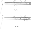
- Figs. 15a and 15b illustrate a preferred circulatory assist apparatus, inserted through a peripheral artery, incorporating two expandable frames, a proximal expandable frame 15.2 and a distal expandable frame 15.4, each including a distally-opening, unidirectional check valve 15.5, and a pumping balloon 15.1 therebetween.
- the apparatus enhances blood flow towards its distal end, opposite to the insertion site.
- the apparatus could be for instance inserted in the upper portion of the jugular vein and advanced towards the heart.
- the proximal check valve 15.5 on expandable frame 15.2 is open, and the distal check valve 15.5 on expandable frame 15.4 is closed, vacuuming, in the described instance, venous blood from the brain.
- the proximal check valve 15.5 on expandable frame 15.2 closes, the distal check valve 15.5 on expandable frame 15.4 opens, and the blood is ejected, in the described instance, towards the right atrium.
- the apparatus is used to enhance venous flow, gating in counterpulsation is not needed.
- small or big balloon volumes and fast or slow inflation rates can be used.
- small balloons in high pumping frequencies may be advantageous in order to prevent stasis and thrombogenesis.
- the balloon volume is sufficient to achieve a pressure increase adjacent the pumping balloon 15.1 above the pressure of the distal site 15.16, in every inflation cycle, in order for blood to be ejected.
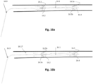
- Figs. 16a and 16b depicts a variant embodiment where the orientation of the unidirectional check valves 16.5 with respect to the apparatus and insertion site are reversed. It is apparent that reverse flow assist apparatuses can be used to achieve fluid vacuum from a body vessel or body cavity, and can be inserted via a distal site and advanced towards the area of deployment. This system can be inserted percutaneously, for example via the femoral vein and advanced upwards into the jugular vein for deployment. In such instances the blood is ejected towards the balloon catheter 16.9 and insertion site, on the proximal sides of the check valves 16.5.
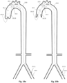
- Figs. 17a and 17b depict another exemplary or preferred embodiment as well as a method of using with a system including expandable-frame-mounted check valve and blocking elements for selectively increasing the blood flow and pressure in a specific compartment of the arterial circulation.
- the apparatus may be inserted through an incision made upstream or downstream from a selected position, with the relative position of the expandable frames (proximal and distal), relative orientation of the check valves (distally-opening and proximally-opening), and relative placement of the blocking element (within the distal or proximal expandable frame) varying appropriately as described earlier above.
- the apparatus may sequentially integrate a distal expandable frame 17.4 including a proximally-opening check valve 17.5 , , a pumping balloon 17.1 , preferably operated in counterpulsation mode, a proximal expandable frame 17.2a including a proximally-opening check valve 17.5, and a more proximal expandable frame 17.2b including a occlusion device 17.14 or other blocking element.
- a distal expandable frame 17.4 including a proximally-opening check valve 17.5 preferably operated in counterpulsation mode
- a proximal expandable frame 17.2a including a proximally-opening check valve 17.5
- a more proximal expandable frame 17.2b including a occlusion device 17.14 or other blocking element.
- the distal check valve 17.5 on the expandable frame 17.4 is a unidirectional 'downstream' valve that defines the most upstream point where pressure augmentation occurs. This may have clinical significance if, for example, one wants to augment flow in the left common carotid artery but not the right subclavian artery. This may be needed in a case where the left common carotid artery is stenotic producing an evolving stroke.
- the proximal check valve 17.5 on the expandable frame 17.2a is also a unidirectional 'downstream' valve that closes with balloon deflation, prevents retrograde flow from below the balloon 17.1, and increases blood flow from above, such as from the LV.
- proximal check valve 17.5 is sufficient to prevent retrograde flow, it is not sufficient to compartmentalize the aorta 17.8 and prioritize for pressure augmentation compartmentalization, e.g., above the lower extremities.
- a second expandable frame 17.2b including a blocking element is used.
- the level of the blocking element defines the lower limit where pressure increase mainly occurs.
- the degree of expansion of the blocking element defines the pressure ratio between the compartmentalized space above and uncompartmentalized space below the blocking element.
- Figs. 17a and 17b illustrate an exemplary implementation where the apparatus is used to increase the blood pressure in an aortic compartment extending from the Aortic Arch 17.17 to the lower aorta 17.10, aiming to prioritize a flow increase towards the brain and renal arteries 17.6, thus the more proximal expandable frame 17.2b is placed under the renal arteries. It has a particular use in ischemic stroke and renal failure patient.
- the pumping balloon 17.1 deflates just prior to the aortic valve 17.12 opening to assist the LV to eject blood out.
- the proximal check valve 17.5 on the expandable frame 17.2a closes because of the pressure fall and the distal check valve 17.5 on the expandable frame 17.4 opens allowing the balloon to vacuum blood out of the heart.
- the upper valve closes 17.2, the lower valve 17.4 opens 17.9 and the blocking element 17.3 directs the flow towards the renal arteries 17.11.
- Deflation of the pumping balloon 18.1 draws blood into the aorta 18.8 which forces the respective valves to an open configuration.
- expansion of the balloon pushes blood downstream, e.g., into the renal arteries 18.6, but also upstream which temporarily closes the upper proximal valve 18.5 on expandable frame 18.2a and therefore impedes retrograde flow.
- This pressure effect may be transmitted as a rebound wave to the aortic insertion site 18.3 and damage the cannulation point, i.e., rupture of the tissue around the cannulation point.
- the more proximal check valve 18.5 on the lower proximal expandable frame 18.2b prevents the direct pressure transmission to the insertion site 18.3 and causes part of the upper aorta 18.7 between the proximal expandable frames 18.2a, 18.2b to dilate, behaving as a buffer chamber, which prevents acute pressure changes.
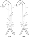
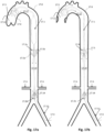
- Figs. 19a and 19b , and 19c and 19d illustrate additional exemplary or preferred embodiments and the basic advantage of the disclosed system. It is generally desirable to position the pumping balloon 19.1 as close as possible to the left ventricle (LV) so as to more efficiently induce a 'vacuum effect.' However under 'normal circumstances' a straight pumping balloon cannot be placed in the aortic arch 19.17 or any other curved vessel. The pumping balloon would traumatize the aortic wall during inflation, because of a 'whipping' phenomenon, attributed mainly to continuous balloon movement during inflation/deflation, the fact that the straight pumping balloon cannot fit in the aortic arch's curvature after inflation, and secondary turbulent flow.
- LV left ventricle
- Figs. 19a and 19b show an apparatus having smaller size and diameter pumping balloon 19.1 that has been advanced in the ascending aorta through a peripheral artery, such as a femoral artery site 19.11.
- the pumping balloon may have an inflated diameter of 12-30 mm and a length of 35-90 mm depending upon patient's size (1.5-1.90 m).
- the pumping balloon shape may be spheroid, oval, cylindrical or any combination thereof.
- a typical pumping balloon of this size wouldn't be able to produce any significant vacuum effect, as blood would be vacuumed also from the brain vessels and other arterial branches from the aortic arch 19.17 (a phenomenon that can be described as 'steal flow') towards the ascending aorta 19.18.
- the balloon preferably operates in a gated, counterpulsation mode, but it can equally effectively operate in a non-gated mode if the cardiac output drops to zero, as it occurs in the context of a cardiac arrest.
- Fig. 19b when the pumping balloon 19.1 deflates, the pressure in the ascending aorta 19.18 drops.
- check valve 19.5 on the proximal expandable frame 19.2 closes, and blood is vacuumed into the ascending aorta from the LV through the open aortic valve 19.12.
- the pumping balloon 19.1 inflates and its total displacement volume is pushed away at high pressure.
- the aortic valve 19.12 has closed, and therefore a substantial fraction of the generated blood flow is compressed between the expanding balloon and against the aortic valve, where the coronary ostiae reside. That increases dramatically the coronary flow compared to any other current device.
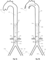
- an additional, distal expandable frame 19.4 may be attached at the distal end of the pumping balloon to centralize the balloon tip portion, further reducing potential for a whipping effect.
- Other structures such as fluidically connected, more proximal balloon 19.26, e.g., an occlusive balloon (as discussed and shown in the context of Figs. 13a and 13b ) or fluidly connected, additional pumping balloon, and/or a lower proximal expandable frame 19.2b including a check valve 19.5 may be added for the purposes described above.
- the additional balloon 19.26 is an additional pumping balloon fluidly connected to the pumping balloon 19.1.
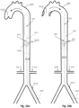
- a modification of this embodiment is presented where the pumping balloon 19.1 is contained within a surrounding expandable frame 19.20 to avoid aortic wall trauma.
- the surrounding expandable frame 19.20 and the proximal expandable frame 19.2 share the same general design features as they have been described above (particularly with reference to Figs 2a through 2c ).
- the dimensions of the expandable frame 19.20 match the dimensions of the inflated pumping balloon 19.1 in diameter, length and volume to avoid mechanical disruption of the frame.
- the expandable frame 19.20 is preferably pretreated to self-expand to a predetermined diameter, having its proximal end joined to the balloon catheter 19.9 or to catheter portions interconnecting the balloon with the proximal expandable frame 19.2, and its distal end sliding freely along a distally-projecting segment from the balloon (as discussed in the context of Figures 1g through 1j ).
- the length of the interconnecting catheter portion(s) must be sufficient to accommodate the collapsed expandable frame.
- the interconnecting catheter portion(s) are preferably made of a hollow tube resistant to kinking, having an elongate shape conforming to the generally curved shape of the aortic arch.
- the distance of each pumping balloon from the previous or next such balloon is such that each pumping balloon has the 'smallest degree of freedom' to move about, preventing balloon to wall contact.
- a length equal to the collapsed length of the interposed expandable frame is desirable.
- Figs. 20a and 20b depict an embodiment and method for augmenting the pressure within the ascending aorta 20.18 and aortic arch 20.17, when a patient is in a state of cardiac arrest, by advancing blood towards the heart from the periphery. If cardiac function ceases completely, the only pool of blood that can be mobilized and sent to the brain and heart is the one that resides within the aorta 20.8.
- the inventor has observed in a series of experiments that if the aortic pressure is increased substantially, to 180 mm Hg or more temporarily (for 10-30 sec), this increases substantially the coronary perfusion to the extent that even a > 1 min completely arrested heart may be restarted.
- Figs. 20a and 20b can be inserted to mobilize all residual arterial aortic blood towards the heart and the brain.
- the apparatus in this embodiment is essentially the same as the apparatus shown in Figs. 6a and 6b , but is inserted through a peripheral artery 20.11 (here the left femoral) at a state of cardiac arrest.
- Distally-opening check valves 20.5 thus enable forced, intentional upstream flow to the ascending aorta 20.18 and aortic arch 20.17, supplying arterial blood to the coronary ostiae.
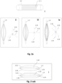
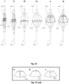
- Fig. 21 shows an exemplary, pre-sized expandable frame or stent structure including a check valve, from fully collapsed ( i ) to partially ( iii-v ) and fully deployed ( vi ).
- the expandable frame can be either self-expanding or inducibly-expanding, and biases the frame into either a loose or tight engagement with the surrounding lumen. The mode of engagement (tight or loose) will depends upon the lumen tissue's elasticity, fragility, and pathology.
- the deployed check valve ( vi ) 21.5 creates an essentially unidirectional fluid passageway.
- the frame has a predetermined size and exhibits a predetermined expansion force. If inducibly-expanding, its size can be assessed either as mentioned earlier or radiographically with suitable radiopaque markers on its surface via fluoroscopy or ultrasound techniques. Generally, whether self-expanding or inducibly-expanding, the expandable frame is pre-sized to open 1-5 mm beyond the width of the lumen and in sufficiently conformity with it to prevent damaging it. A thin synthetic coating may cover the frame member surfaces that engage the surrounding tissue, thereby preventing direct contact between the members and the tissue.
- the check valve 21.5 is composed of a thin synthetic material, forming a membrane and is anchored on the frame, preferably on the inner surface of the frame members.
- This membrane is made of a biocompatible material (such us TEFLON, DACRON, polyethylene, polyamide, nylon, polyurethane, natural rubber, synthetic rubber, thermoplastic elastomer or thermoset polymer and the like), and may be treated to have anti-thrombotic properties. It preferably takes the form of a truncated cone. The diameter and perimeter of the neck of the cone is larger than the corresponding diameter and perimeter of the expanded frame 21.2 at the same axial location so as to be able to bulge towards the center of the frame.
- the diameter of the base of the cone matches the diameter of the expanded frame 21.2 at the same axial location, and the perimeter is the same as an imaginary continuous perimeter of the frame at the same axial location.
- the number frame members corresponds to the number of leaflets 21.5a, 21.5b, etc.
- the frame members support the check valve structure in the same way that stent arms support a tissue bioprosthesis, like those used for tissue valve replacement in humans.
- the check valve structure is generally attached to the inner surfaces and/or sides of the individual frame members, such that when the frame 21.2 is expanded the check valve 21.5 almost simulates a truncated cone, as it is shown in figure 24 sub c, with its neck end portions bulging towards the lumen walls.
- the check valve 21.5 closes the collapsing neck structure forms a bileaflet shape (not shown), a trileaflet shape ( Fig. 21 sub b , a quadrileaflet shape, ( Fig. 21 sub a ), etc. depending upon whether the neck is attached to each frame member, each other frame member, etc. and the number of frame members.
- the thicker the check valve material the more difficult it is for the check valve at the same axial location 21.5 to collapse at a small size, but the more supple and resistant it becomes.
- multi-leaflet valves (2-8 leaflets) made of thin material collapse well to produce a thin structure whilst maintaining their resistance and ability to follow a patterned movement even with repetitive opening and closure.
- Illustrated and suggested embodiments may be particularly useful in the common case where a femorally inserted IAB is more or less used to draw ('vacuum') blood from a failing heart.
- An expandable frame, mounted upon the balloon catheter tube and combined with check valve placed just below the IAB allows blood to flow downstream -with relation to normal blood flow- but not upstream. Subsequently during the pumping balloon's inflation there is no 'retrograde' flow towards the balloon, e.g., from the lower aorta. This augments the off-loading effect of the apparatus' counterpulsation on a failing or compromised heart compared with conventional IABs.
- Illustrated and suggested embodiments may act like an LVAD. More specifically a small pumping balloon (5-12 cm in length, 1-3.5 cm in diameter) may be mounted on a balloon catheter and placed in the ascending aorta. It may be further combined with an expandable frame, integrating a check valve, on its proximal balloon portion thus allowing downstream flow but preventing upstream flow. The system may be fed through the femoral artery and positioned such that the check valve resides at the level of the right subclavian artery.
- the pumping balloon may be surrounded by an expandable frame thereby preventing elastic recoil during the balloon's deflation and trauma to the ascending aorta during the balloon's inflation.
- the expandable frame may be funnel-shaped or malecot-type.
- renal failure may occur due to a transient decrease of renal flow, although the heart and the brain may not be particularly on demand.
- brain ischemia may occur although the kidneys may not be particularly on demand.
- Illustrated and suggested embodiments eliminate this 'flow waste' by including a check valve placed just downstream form the arteries supplying the organ that is not on demand, thereby preventing 'flow waste' upon said level and giving priority to an organ below this level.
- This downstream-opening check valve is combined with a more downstream pumping balloon so that the check valve is positioned above it. This combination will allow downstream flow (in relation to the normal blood flow from the heart) during the balloon's deflation, but prevent upstream flow during the balloon's inflation.
- An additional downstream-opening check valve placed downstream from the balloon -as described before- will increase 'vacuuming' from the heart.
- Illustrated and suggested embodiments may be particularly useful in the case of a heart on CPB, and may supply counterpulsation through an aortic cannulation site.
- an pumping balloon mounted on a balloon catheter, having expandable frames on either side of pumping balloon, each including a check valve, may be fed through the aortic cannulation site. Both check valves allow downstream flow, but prevent upstream flow.
- the pumping balloon is placed at the level of the renal arteries and appropriately centered -thereby avoiding transient renal artery flow blockade during counterpulsation.
- the expandable frames deploy outwardly and position the check valves above and below the renal arteries, defining a 'renal arteries compartment'.
- the proximal or upstream check valve will allow blood to enter the 'renal arteries compartment' upon the pumping balloon's deflation, but it will prevent blood 'flow waste' above said proximal check valve during the pumping balloon's inflation, thereby increasing the flow to the renal arteries.
- the distal or downstream check valve will prevent retrograde flow from the lower limbs during the pumping balloon's inflation, thereby increasing downstream flow, 'vacuum' effect, and blood pooling in the 'renal arteries compartment'.
- Illustrated and suggested embodiments may be particularly useful in the case of pre-renal failure where an increase of renal blood flow is desired. More specifically an pumping balloon mounted on a balloon catheter as described above may be inserted through the femoral artery and used to specifically increase renal blood flow.
- Illustrated and suggested embodiments may be particularly useful in the case of the brain ischemia where an increase of brain blood flow is desired.
- An pumping balloon mounted on a balloon catheter, having expandable frames on either side of pumping balloon, each including a check valve, is fed through the femoral artery. Both check valves allow downstream flow, but prevent upstream flow.
- the pumping balloon is placed at the level of the thoracic aorta and appropriately centered - thereby avoiding balloon-to-aortic-wall contact during counterpulsation.
- the expandable frames deploy outwardly and position the check valves above and below the level of the innominate and right subclavian arteries, defining a 'brain arteries compartment'.
- the pumping balloon operates in counterpulsation mode, and the distal or upstream check valve will allow blood to enter upon the pumping balloon's deflation, but it will prevent blood 'flow waste' towards the heart during the pumping balloon's inflation, thereby increasing the flow to the encephalic arteries.
- the proximal or downstream check valve will prevent retrograde flow from the lower limbs during the balloon's deflation, thereby increasing downstream flow, 'vacuum' effect and, blood pooling in the 'brain arteries compartment'.
- the system may further comprise a lower proximal or downstream valve, which functions as a blocking element during the pumping balloon's inflation.
- Illustrated and suggested embodiments for such applications typically include a pumping balloon, mounted on a balloon catheter, with expandable frames (proximal and distal) disposed on either side, which are fed through a peripheral vessel.
- Either expandable frame may include a passive unidirectional check valve mounted thereupon.
- the pumping balloon is placed within the peripheral vessel and appropriately centered - thereby avoiding transient flow blockade during counterpulsation, if used.
- the expandable frames are deployed outwardly, and thus said unidirectional check valves are also deployed, above and below the peripheral arteries defining an 'underperfused area'.
- Proximal expandable frame's check valve allows downstream flow towards the pumping balloon, but prevents upstream flow, allowing blood to enter the underperfused area upon the pumping balloon's deflation, but preventing blood 'flow waste' above said proximal check valve during the pumping balloon's inflation, thereby increasing the flow into the specific underperfused area.
- Distal expandable frame's check valve will prevent retrograde flow from the lower limbs during pumping balloon's inflation, thereby increasing downstream flow, 'vacuum' effect, and blood pooling in the 'underperfused area'.
- an expandable member in combination with an IAB-like pumping balloon, creating upstream flow to the brain or any part of the arterial circulation.
- This comprise a pumping balloon, placed downstream in relation with an expandable 'blocking element' and the normal blood flow, which counterbalances the decrease of the downstream flow secondary to the obstruction.
- a small pumping balloon, combined with a proximal expandable frame having a 'blocking element,' is inserted through a peripheral vessel (such as the femoral artery) and placed below the aortic arch. Upon expansion said expandable frame and blocking element occludes partially the aortic flow, thereby creating retrograde flow to the brain or any portion of the arterial circulation.
Landscapes
- Health & Medical Sciences (AREA)
- Heart & Thoracic Surgery (AREA)
- Engineering & Computer Science (AREA)
- Cardiology (AREA)
- General Health & Medical Sciences (AREA)
- Biomedical Technology (AREA)
- Hematology (AREA)
- Life Sciences & Earth Sciences (AREA)
- Animal Behavior & Ethology (AREA)
- Mechanical Engineering (AREA)
- Public Health (AREA)
- Veterinary Medicine (AREA)
- Anesthesiology (AREA)
- Vascular Medicine (AREA)
- Physics & Mathematics (AREA)
- Transplantation (AREA)
- Geometry (AREA)
- Urology & Nephrology (AREA)
- Optics & Photonics (AREA)
- Media Introduction/Drainage Providing Device (AREA)
- External Artificial Organs (AREA)
- Prostheses (AREA)
Applications Claiming Priority (4)
| Application Number | Priority Date | Filing Date | Title |
|---|---|---|---|
| US201361837173P | 2013-06-20 | 2013-06-20 | |
| EP14793282.6A EP3010563B1 (en) | 2013-06-20 | 2014-06-20 | Intra-aortic balloon apparatus for improving flow, counterpulsation and haemodynamics |
| EP18204523.7A EP3466458B1 (en) | 2013-06-20 | 2014-06-20 | Intra-aortic balloon apparatus and assist devices, for improving flow, counterpulsation, and haemodynamics |
| PCT/IB2014/001672 WO2014203078A2 (en) | 2013-06-20 | 2014-06-20 | Intra-aortic balloon apparatus, assist devices and methods for improving flow, counterpulsation and haemodynamics |
Related Parent Applications (2)
| Application Number | Title | Priority Date | Filing Date |
|---|---|---|---|
| EP14793282.6A Division EP3010563B1 (en) | 2013-06-20 | 2014-06-20 | Intra-aortic balloon apparatus for improving flow, counterpulsation and haemodynamics |
| EP18204523.7A Division EP3466458B1 (en) | 2013-06-20 | 2014-06-20 | Intra-aortic balloon apparatus and assist devices, for improving flow, counterpulsation, and haemodynamics |
Publications (2)
| Publication Number | Publication Date |
|---|---|
| EP4162972A1 EP4162972A1 (en) | 2023-04-12 |
| EP4162972B1 true EP4162972B1 (en) | 2025-04-16 |
Family
ID=51846712
Family Applications (3)
| Application Number | Title | Priority Date | Filing Date |
|---|---|---|---|
| EP22208142.4A Active EP4162972B1 (en) | 2013-06-20 | 2014-06-20 | Intra-aortic balloon apparatus, assist devices, for improving flow, counterpulsation, and haemodynamics |
| EP18204523.7A Active EP3466458B1 (en) | 2013-06-20 | 2014-06-20 | Intra-aortic balloon apparatus and assist devices, for improving flow, counterpulsation, and haemodynamics |
| EP14793282.6A Active EP3010563B1 (en) | 2013-06-20 | 2014-06-20 | Intra-aortic balloon apparatus for improving flow, counterpulsation and haemodynamics |
Family Applications After (2)
| Application Number | Title | Priority Date | Filing Date |
|---|---|---|---|
| EP18204523.7A Active EP3466458B1 (en) | 2013-06-20 | 2014-06-20 | Intra-aortic balloon apparatus and assist devices, for improving flow, counterpulsation, and haemodynamics |
| EP14793282.6A Active EP3010563B1 (en) | 2013-06-20 | 2014-06-20 | Intra-aortic balloon apparatus for improving flow, counterpulsation and haemodynamics |
Country Status (7)
| Country | Link |
|---|---|
| US (4) | US10137231B2 (enExample) |
| EP (3) | EP4162972B1 (enExample) |
| JP (4) | JP6725414B2 (enExample) |
| AU (5) | AU2014282904B2 (enExample) |
| CA (2) | CA3115509C (enExample) |
| ES (3) | ES2937726T3 (enExample) |
| WO (1) | WO2014203078A2 (enExample) |
Families Citing this family (49)
| Publication number | Priority date | Publication date | Assignee | Title |
|---|---|---|---|---|
| CN104470579B (zh) | 2012-06-06 | 2018-06-01 | 洋红医疗有限公司 | 人工肾脏瓣膜 |
| EP4233702A3 (en) | 2013-03-13 | 2023-12-20 | Magenta Medical Ltd. | Manufacture of an impeller |
| US10583231B2 (en) | 2013-03-13 | 2020-03-10 | Magenta Medical Ltd. | Blood pump |
| WO2016004355A1 (en) * | 2014-07-03 | 2016-01-07 | The Trustees Of Columbia University In The City Of New York | Introducer for accessing coronary sinus via right parasternal mediastinotomy |
| US20160055985A1 (en) * | 2014-08-25 | 2016-02-25 | Siemens Industry, Inc. | Circuit breakers, circuit breaker line power assemblies, and operational methods |
| US11291824B2 (en) | 2015-05-18 | 2022-04-05 | Magenta Medical Ltd. | Blood pump |
| WO2018039461A1 (en) * | 2016-08-24 | 2018-03-01 | Nupulsecv, Inc. | Blood pump assembly and method of use thereof |
| US11389169B2 (en) | 2016-09-01 | 2022-07-19 | Microvention, Inc. | Temporary aortic occlusion device |
| EP3506840A4 (en) * | 2016-09-01 | 2020-05-06 | Microvention, Inc. | TEMPORARY AERIAL LOCKING DEVICE |
| EP3518825B1 (en) | 2016-09-29 | 2020-05-27 | Magenta Medical Ltd. | Blood vessel tube |
| CN115040776A (zh) * | 2016-10-25 | 2022-09-13 | 马真塔医药有限公司 | 心室辅助装置 |
| DE102016122268B4 (de) * | 2016-11-18 | 2021-12-30 | Cardiobridge Gmbh | Katheterpumpe mit einem Pumpenkopf zum Einsetzen in die Aorta |
| US10179197B2 (en) | 2016-11-21 | 2019-01-15 | Cardiobridge Gmbh | Catheter pump with a pump head for insertion into the aorta |
| US11033727B2 (en) * | 2016-11-23 | 2021-06-15 | Magenta Medical Ltd. | Blood pumps |
| ES2863628T3 (es) * | 2017-05-04 | 2021-10-11 | Abiomed Europe Gmbh | Bomba de sangre intravascular con balón |
| EP3691710A4 (en) * | 2017-10-06 | 2021-07-21 | Troy Thornton | DEVICE FOR CLEANSING THE KIDNEY |
| US11351355B2 (en) * | 2017-10-19 | 2022-06-07 | Datascope Corporation | Devices for pumping blood, related systems, and related methods |
| CN115192897B (zh) | 2018-01-10 | 2025-08-05 | 马真塔医药有限公司 | 心室辅助装置 |
| US10905808B2 (en) | 2018-01-10 | 2021-02-02 | Magenta Medical Ltd. | Drive cable for use with a blood pump |
| US10893927B2 (en) | 2018-03-29 | 2021-01-19 | Magenta Medical Ltd. | Inferior vena cava blood-flow implant |
| US11020582B2 (en) * | 2018-04-20 | 2021-06-01 | Cardiovascular Systems, Inc. | Intravascular pump with expandable region |
| US11167121B2 (en) * | 2018-05-15 | 2021-11-09 | Cardiovascular Systems, Inc. | Intravascular pump with integrated isolated conductor(s) and methods thereof |
| US11141580B2 (en) * | 2018-05-15 | 2021-10-12 | Cardiovascular Systems, Inc. | Intravascular blood pump system with integrated conductor(s) in housing and methods thereof |
| EP3586900A1 (en) * | 2018-06-28 | 2020-01-01 | Medinice S.A. | Cannula for minimally invasive surgical tricuspid valve repair |
| US11219753B2 (en) * | 2018-07-30 | 2022-01-11 | Cardiovascular Systems, Inc. | Intravascular pump with expandable and collapsible inlet region and methods thereof |
| CN109395185A (zh) * | 2018-11-15 | 2019-03-01 | 安徽通灵仿生科技有限公司 | 一种辅助左心室功能的搏动式导管装置 |
| US11426563B2 (en) | 2018-12-03 | 2022-08-30 | Nxt Biomedical, Llc | Blood pump or balloon cycling and venous occlusion |
| CN115040778B (zh) | 2019-01-24 | 2025-07-25 | 马真塔医药有限公司 | 心室辅助装置 |
| AU2020230048B2 (en) * | 2019-02-26 | 2025-06-26 | White Swell Medical Ltd | Devices and methods for treating edema |
| NL2022660B1 (en) | 2019-03-01 | 2020-09-15 | Stichting Katholieke Univ | Heart Assist Device |
| US11185334B2 (en) | 2019-03-28 | 2021-11-30 | DePuy Synthes Products, Inc. | Single lumen reduced profile occlusion balloon catheter |
| US12156978B2 (en) | 2019-05-17 | 2024-12-03 | Nupulsecv, Inc. | Intravascularly delivered blood pumps and associated devices, systems, and methods |
| EP3972661B1 (en) | 2019-05-23 | 2024-09-11 | Magenta Medical Ltd. | Blood pumps |
| CN110876673B (zh) * | 2019-11-08 | 2022-04-22 | 中国医学科学院阜外医院 | 主动脉内双气囊驱动反搏导管装置 |
| EP4052754B1 (en) | 2020-04-07 | 2023-10-25 | Magenta Medical Ltd. | Axial shaft with joint |
| US11219754B2 (en) | 2020-05-20 | 2022-01-11 | Rainbow Medical Ltd. | Passive pump |
| US11395910B2 (en) | 2020-05-20 | 2022-07-26 | Rainbow Medical Ltd. | Passive pump |
| CN113893444B (zh) * | 2020-06-22 | 2025-02-07 | 上海微创心脉医疗科技(集团)股份有限公司 | 一种医用装置 |
| US20240024657A1 (en) * | 2020-12-09 | 2024-01-25 | Nxt Biomedical, Llc | Circulatory support devices and methods |
| WO2022140628A1 (en) | 2020-12-22 | 2022-06-30 | Boston Scientific Scimed Inc. | Constraint delivery - hinge & constraint delivery - corset |
| NL2028130B1 (en) | 2021-05-03 | 2022-11-10 | Cardiacbooster B V | Cardiac assist device with high frequency operation |
| US11484700B1 (en) | 2021-10-25 | 2022-11-01 | Yossi Gross | Mechanical treatment of heart failure |
| US11357629B1 (en) | 2021-10-25 | 2022-06-14 | Rainbow Medical Ltd. | Diastolic heart failure treatment |
| US20240390665A1 (en) * | 2023-05-22 | 2024-11-28 | Phap Medical, Llc | Systems and methods for an intra-aortic peristalsis heart assist pump |
| WO2025041109A1 (en) * | 2023-08-24 | 2025-02-27 | Cardiacbooster B.V. | Circulatory assist device with vascular lumen sealing |
| WO2025083650A1 (en) * | 2023-10-20 | 2025-04-24 | Cardiacbooster B.V. | Circulatory assist device with multi-leaflet valve |
| CN117582577B (zh) * | 2024-01-19 | 2024-04-12 | 中国人民解放军总医院第四医学中心 | 一种改进的肢体灌注装置 |
| WO2025169124A1 (en) | 2024-02-06 | 2025-08-14 | Anagnostopoulos Constantinos | Intra-aortic balloon assist devices, circulatory assist devices, and one-way valve devices for use with the same |
| CN119971268B (zh) * | 2025-04-11 | 2025-07-08 | 鼎科医疗技术(苏州)有限公司 | 一种光纤球囊导管 |
Family Cites Families (60)
| Publication number | Priority date | Publication date | Assignee | Title |
|---|---|---|---|---|
| US4077394A (en) | 1976-08-25 | 1978-03-07 | Mccurdy Martin D | Integral pressure sensor probe for a cardiac assistance device |
| US4407271A (en) | 1980-07-28 | 1983-10-04 | Peter Schiff | Apparatus for left heart assist |
| US4522195A (en) | 1981-05-25 | 1985-06-11 | Peter Schiff | Apparatus for left heart assist |
| US4444186A (en) | 1981-06-15 | 1984-04-24 | Datascope Corporation | Envelope wrapping system for intra-aortic balloon |
| US4515587A (en) | 1983-02-14 | 1985-05-07 | Smec, Inc. | IAB having apparatus for assuring proper balloon inflation and deflation |
| US4785795A (en) | 1985-07-15 | 1988-11-22 | Abiomed Cardiovascular, Inc. | High-frequency intra-arterial cardiac support system |
| US5176619A (en) | 1989-05-05 | 1993-01-05 | Jacob Segalowitz | Heart-assist balloon pump with segmented ventricular balloon |
| ES2020787A6 (es) | 1990-07-20 | 1991-09-16 | Figuera Aymerich Diego | Bomba intra-ventricular expansible de asistencia circulatoria. |
| US5122113A (en) | 1991-03-27 | 1992-06-16 | Hattler Brack G | Inflatable percutaneous oxygenator |
| US5405378A (en) | 1992-05-20 | 1995-04-11 | Strecker; Ernst P. | Device with a prosthesis implantable in the body of a patient |
| US5318501A (en) | 1992-09-24 | 1994-06-07 | Medtronic, Inc. | Linear motion, muscle-actuated cardiac assist device |
| US5336178A (en) | 1992-11-02 | 1994-08-09 | Localmed, Inc. | Intravascular catheter with infusion array |
| DE4240177C2 (de) | 1992-11-30 | 1997-02-13 | Ruesch Willy Ag | Selbstexpandierender Stent für Hohlorgane |
| JPH06296703A (ja) * | 1993-04-19 | 1994-10-25 | Toyobo Co Ltd | 心補助システム |
| JPH07265410A (ja) * | 1994-03-31 | 1995-10-17 | Terumo Corp | 大動脈内用バルーンカテーテルおよび血液補助循環装置 |
| US5913871A (en) | 1996-09-25 | 1999-06-22 | Medtronic, Inc. | Balloon modification for improved stent fixation and deployment |
| US5820542A (en) * | 1996-10-31 | 1998-10-13 | Momentum Medical, Inc. | Modified circulatory assist device |
| EP0850607A1 (en) * | 1996-12-31 | 1998-07-01 | Cordis Corporation | Valve prosthesis for implantation in body channels |
| US5868783A (en) | 1997-04-16 | 1999-02-09 | Numed, Inc. | Intravascular stent with limited axial shrinkage |
| US6143016A (en) | 1997-04-21 | 2000-11-07 | Advanced Cardiovascular Systems, Inc. | Sheath and method of use for a stent delivery system |
| US5810871A (en) | 1997-04-29 | 1998-09-22 | Medtronic, Inc. | Stent delivery system |
| US5957949A (en) | 1997-05-01 | 1999-09-28 | World Medical Manufacturing Corp. | Percutaneous placement valve stent |
| US5976181A (en) | 1997-09-22 | 1999-11-02 | Ave Connaught | Balloon mounted stent and method therefor |
| ATE404123T1 (de) | 1997-11-12 | 2008-08-15 | Genesis Technologies Llc | Vorrichtung zum entfernen von okklusionen in biologischen durchgängen |
| US7044134B2 (en) | 1999-11-08 | 2006-05-16 | Ev3 Sunnyvale, Inc | Method of implanting a device in the left atrial appendage |
| US6149578A (en) | 1999-02-04 | 2000-11-21 | My-Tech, Inc. | Piston-action intra-aortic coronary assist device |
| US6210318B1 (en) | 1999-03-09 | 2001-04-03 | Abiomed, Inc. | Stented balloon pump system and method for using same |
| US6136025A (en) | 1999-07-27 | 2000-10-24 | Barbut; Denise R. | Endoscopic arterial pumps for treatment of cardiac insufficiency and venous pumps for right-sided cardiac support |
| US6506202B1 (en) | 2000-07-10 | 2003-01-14 | Advanced Cardiovascular Systems, Inc. | Expandable stent dimensional retention system and method |
| EP1412014A4 (en) | 2001-06-14 | 2005-06-15 | Cook Inc | ENDOVASCULAR FILTER |
| US7063679B2 (en) * | 2002-09-20 | 2006-06-20 | Flowmedica, Inc. | Intra-aortic renal delivery catheter |
| AU2002952730A0 (en) | 2002-11-15 | 2002-12-05 | Sunshine Heart Company Pty Ltd | An Intraluminal Inflatable Counter-pulsation Heart Assist Device |
| US7686824B2 (en) | 2003-01-21 | 2010-03-30 | Angioscore, Inc. | Apparatus and methods for treating hardened vascular lesions |
| US20040215311A1 (en) * | 2003-04-28 | 2004-10-28 | Kantor John D. | Method and system for improving stent retention using stent openings |
| US8226541B2 (en) * | 2003-06-11 | 2012-07-24 | L. Vad Technology, Inc. | Methods of making aortic counter pulsation cardiac assist devices with three dimensional tortuous shape |
| US7374531B1 (en) | 2003-06-11 | 2008-05-20 | L. Vad Technology, Inc. | Long term ambulatory intra-aortic balloon pump with three dimensional tortuous shape |
| CN1946449A (zh) * | 2004-02-26 | 2007-04-11 | V-卡迪亚控股有限公司 | 分离心脏循环 |
| US20090038752A1 (en) * | 2005-02-09 | 2009-02-12 | Adel Weng | Reinforced balloon for a catheter |
| CN101049267B (zh) | 2006-04-03 | 2010-12-22 | 孟坚 | 医疗用闭塞器械 |
| US7914436B1 (en) | 2006-06-12 | 2011-03-29 | Abiomed, Inc. | Method and apparatus for pumping blood |
| US20080033476A1 (en) | 2006-08-07 | 2008-02-07 | Greene Joel M | Catheter balloon with controlled failure sheath |
| US7722568B2 (en) * | 2007-01-29 | 2010-05-25 | Onset Medical Corporation | Expandable intra-aortic balloon pump sheath |
| WO2009126747A1 (en) | 2008-04-08 | 2009-10-15 | Reverse Medical Corporation | Occlusion device and method of use |
| DE602007004842D1 (de) | 2007-07-18 | 2010-04-01 | Surgery In Motion Ltd | Vorrichtung zur Unterstützung bei der Herzbehandlung |
| WO2009091965A1 (en) | 2008-01-18 | 2009-07-23 | Med Institute, Inc. | Intravascular device attachment system having tubular expandable body |
| EP2594230B1 (en) | 2008-02-29 | 2021-04-28 | Edwards Lifesciences Corporation | Expandable member for deploying a prosthetic device |
| CA2728576C (en) | 2008-05-06 | 2014-07-08 | The Cleveland Clinic Foundation | Balloon for a body lumen and method of use |
| GB2469072A (en) * | 2009-03-31 | 2010-10-06 | Royal Brompton & Harefield Nhs | Guidewire with Anchor for a catheter |
| US20100298922A1 (en) | 2009-05-22 | 2010-11-25 | Ulbrich Precision Metals Limited | Angioplasty Assembly |
| US8740961B2 (en) * | 2009-08-13 | 2014-06-03 | Richard Eustis Fulton, III | Method for treating a target site in a vascular body channel |
| EP2338539A1 (de) | 2009-12-23 | 2011-06-29 | ECP Entwicklungsgesellschaft mbH | Pumpeneinrichtung mit einer Detektionseinrichtung |
| US8540669B2 (en) * | 2010-04-30 | 2013-09-24 | Abbott Cardiovascular Systems Inc. | Catheter system providing step reduction for postconditioning |
| WO2011136815A1 (en) * | 2010-04-30 | 2011-11-03 | Abbott Cardiovascular Systems Inc. | Catheter system having a fluid circuit |
| CN103561686B (zh) * | 2011-03-03 | 2016-03-30 | 英派尔科技开发有限公司 | 用于可膨胀球囊支架的经皮输送的临时灌注通道 |
| US9415193B2 (en) | 2011-03-04 | 2016-08-16 | W. L. Gore & Associates, Inc. | Eluting medical devices |
| US20120330092A1 (en) | 2011-06-23 | 2012-12-27 | Akira Shiose | Device, system, and method for modulating cardiac function |
| US10327790B2 (en) * | 2011-08-05 | 2019-06-25 | Route 92 Medical, Inc. | Methods and systems for treatment of acute ischemic stroke |
| US9474882B2 (en) | 2013-02-26 | 2016-10-25 | Prytime Medical Devices, Inc. | Fluoroscopy-independent balloon guided occlusion catheter and methods |
| JP2022097269A (ja) * | 2020-12-18 | 2022-06-30 | ユニ・チャーム株式会社 | 情報処理装置、情報処理方法及び情報処理プログラム |
| JP2023173233A (ja) * | 2022-05-25 | 2023-12-07 | 富士電機株式会社 | ワイヤリフトオフ検出装置及びワイヤリフトオフ検出方法 |
-
2014
- 2014-06-20 ES ES18204523T patent/ES2937726T3/es active Active
- 2014-06-20 ES ES14793282T patent/ES2774270T3/es active Active
- 2014-06-20 JP JP2016520757A patent/JP6725414B2/ja active Active
- 2014-06-20 EP EP22208142.4A patent/EP4162972B1/en active Active
- 2014-06-20 CA CA3115509A patent/CA3115509C/en active Active
- 2014-06-20 WO PCT/IB2014/001672 patent/WO2014203078A2/en not_active Ceased
- 2014-06-20 EP EP18204523.7A patent/EP3466458B1/en active Active
- 2014-06-20 CA CA2916140A patent/CA2916140C/en active Active
- 2014-06-20 ES ES22208142T patent/ES3036176T3/es active Active
- 2014-06-20 US US14/899,804 patent/US10137231B2/en active Active
- 2014-06-20 AU AU2014282904A patent/AU2014282904B2/en active Active
- 2014-06-20 EP EP14793282.6A patent/EP3010563B1/en active Active
-
2018
- 2018-06-12 US US16/006,111 patent/US11602628B2/en active Active
-
2019
- 2019-03-05 AU AU2019201522A patent/AU2019201522B2/en active Active
-
2020
- 2020-06-25 JP JP2020109995A patent/JP7092827B2/ja active Active
-
2021
- 2021-03-24 AU AU2021201849A patent/AU2021201849B2/en active Active
-
2022
- 2022-06-16 JP JP2022097269A patent/JP2022123061A/ja active Pending
-
2023
- 2023-03-13 US US18/182,738 patent/US12023481B2/en active Active
- 2023-07-27 AU AU2023208180A patent/AU2023208180A1/en not_active Abandoned
- 2023-10-04 JP JP2023173233A patent/JP2023171940A/ja active Pending
-
2024
- 2024-07-02 US US18/761,466 patent/US20240350795A1/en active Pending
-
2025
- 2025-09-23 AU AU2025237909A patent/AU2025237909A1/en active Pending
Also Published As
Similar Documents
| Publication | Publication Date | Title |
|---|---|---|
| US12023481B2 (en) | Intra-aortic balloon apparatus, assist devices and methods for improving flow, counterpulsation and haemodynamics | |
| CN111246897B (zh) | 用于泵送血液的装置、相关系统和相关方法 | |
| US20230102060A1 (en) | Methods for managing blood flow | |
| CN106714861B (zh) | 导管 | |
| CN115942919A (zh) | 用于修改体腔中的流动的急性和慢性装置以及其使用方法 | |
| US6136025A (en) | Endoscopic arterial pumps for treatment of cardiac insufficiency and venous pumps for right-sided cardiac support | |
| WO2000053240A1 (en) | Intra-aortic balloon pump system with associated stent and method for using same | |
| US20180317932A1 (en) | Aortic Occlusion Balloon Apparatus, System and Method of Making | |
| HK40092583B (en) | Intra-aortic balloon apparatus, assist devices, for improving flow, counterpulsation, and haemodynamics | |
| HK40092583A (en) | Intra-aortic balloon apparatus, assist devices, for improving flow, counterpulsation, and haemodynamics | |
| HK40007055B (en) | Intra-aortic balloon apparatus, assist devices, and methods for improving flow, counterpulsation, and haemodynamics | |
| HK40007055A (en) | Intra-aortic balloon apparatus, assist devices, and methods for improving flow, counterpulsation, and haemodynamics |
Legal Events
| Date | Code | Title | Description |
|---|---|---|---|
| PUAI | Public reference made under article 153(3) epc to a published international application that has entered the european phase |
Free format text: ORIGINAL CODE: 0009012 |
|
| STAA | Information on the status of an ep patent application or granted ep patent |
Free format text: STATUS: REQUEST FOR EXAMINATION WAS MADE |
|
| 17P | Request for examination filed |
Effective date: 20221117 |
|
| AC | Divisional application: reference to earlier application |
Ref document number: 3010563 Country of ref document: EP Kind code of ref document: P Ref document number: 3466458 Country of ref document: EP Kind code of ref document: P |
|
| AK | Designated contracting states |
Kind code of ref document: A1 Designated state(s): AL AT BE BG CH CY CZ DE DK EE ES FI FR GB GR HR HU IE IS IT LI LT LU LV MC MK MT NL NO PL PT RO RS SE SI SK SM TR |
|
| REG | Reference to a national code |
Ref country code: HK Ref legal event code: DE Ref document number: 40092583 Country of ref document: HK |
|
| GRAP | Despatch of communication of intention to grant a patent |
Free format text: ORIGINAL CODE: EPIDOSNIGR1 |
|
| STAA | Information on the status of an ep patent application or granted ep patent |
Free format text: STATUS: GRANT OF PATENT IS INTENDED |
|
| RIC1 | Information provided on ipc code assigned before grant |
Ipc: A61M 60/896 20210101ALI20241024BHEP Ipc: A61M 60/865 20210101ALI20241024BHEP Ipc: A61M 60/861 20210101ALI20241024BHEP Ipc: A61M 60/843 20210101ALI20241024BHEP Ipc: A61M 60/841 20210101ALI20241024BHEP Ipc: A61M 60/497 20210101ALI20241024BHEP Ipc: A61M 60/33 20210101ALI20241024BHEP Ipc: A61M 60/295 20210101ALI20241024BHEP Ipc: A61M 60/139 20210101ALI20241024BHEP Ipc: A61M 60/13 20210101AFI20241024BHEP |
|
| INTG | Intention to grant announced |
Effective date: 20241104 |
|
| GRAS | Grant fee paid |
Free format text: ORIGINAL CODE: EPIDOSNIGR3 |
|
| GRAA | (expected) grant |
Free format text: ORIGINAL CODE: 0009210 |
|
| STAA | Information on the status of an ep patent application or granted ep patent |
Free format text: STATUS: THE PATENT HAS BEEN GRANTED |
|
| AC | Divisional application: reference to earlier application |
Ref document number: 3010563 Country of ref document: EP Kind code of ref document: P Ref document number: 3466458 Country of ref document: EP Kind code of ref document: P |
|
| AK | Designated contracting states |
Kind code of ref document: B1 Designated state(s): AL AT BE BG CH CY CZ DE DK EE ES FI FR GB GR HR HU IE IS IT LI LT LU LV MC MK MT NL NO PL PT RO RS SE SI SK SM TR |
|
| REG | Reference to a national code |
Ref country code: GB Ref legal event code: FG4D |
|
| REG | Reference to a national code |
Ref country code: CH Ref legal event code: EP Ref country code: DE Ref legal event code: R096 Ref document number: 602014091819 Country of ref document: DE |
|
| REG | Reference to a national code |
Ref country code: IE Ref legal event code: FG4D |
|
| REG | Reference to a national code |
Ref country code: NL Ref legal event code: FP |
|
| REG | Reference to a national code |
Ref country code: ES Ref legal event code: FG2A Ref document number: 3036176 Country of ref document: ES Kind code of ref document: T3 Effective date: 20250915 Ref country code: AT Ref legal event code: MK05 Ref document number: 1785152 Country of ref document: AT Kind code of ref document: T Effective date: 20250416 |
|
| PG25 | Lapsed in a contracting state [announced via postgrant information from national office to epo] |
Ref country code: FI Free format text: LAPSE BECAUSE OF FAILURE TO SUBMIT A TRANSLATION OF THE DESCRIPTION OR TO PAY THE FEE WITHIN THE PRESCRIBED TIME-LIMIT Effective date: 20250416 Ref country code: PT Free format text: LAPSE BECAUSE OF FAILURE TO SUBMIT A TRANSLATION OF THE DESCRIPTION OR TO PAY THE FEE WITHIN THE PRESCRIBED TIME-LIMIT Effective date: 20250818 |
|
| REG | Reference to a national code |
Ref country code: LT Ref legal event code: MG9D |
|
| PG25 | Lapsed in a contracting state [announced via postgrant information from national office to epo] |
Ref country code: NO Free format text: LAPSE BECAUSE OF FAILURE TO SUBMIT A TRANSLATION OF THE DESCRIPTION OR TO PAY THE FEE WITHIN THE PRESCRIBED TIME-LIMIT Effective date: 20250716 Ref country code: GR Free format text: LAPSE BECAUSE OF FAILURE TO SUBMIT A TRANSLATION OF THE DESCRIPTION OR TO PAY THE FEE WITHIN THE PRESCRIBED TIME-LIMIT Effective date: 20250717 |
|
| PG25 | Lapsed in a contracting state [announced via postgrant information from national office to epo] |
Ref country code: PL Free format text: LAPSE BECAUSE OF FAILURE TO SUBMIT A TRANSLATION OF THE DESCRIPTION OR TO PAY THE FEE WITHIN THE PRESCRIBED TIME-LIMIT Effective date: 20250416 |
|
| PG25 | Lapsed in a contracting state [announced via postgrant information from national office to epo] |
Ref country code: BG Free format text: LAPSE BECAUSE OF FAILURE TO SUBMIT A TRANSLATION OF THE DESCRIPTION OR TO PAY THE FEE WITHIN THE PRESCRIBED TIME-LIMIT Effective date: 20250416 |
|
| PG25 | Lapsed in a contracting state [announced via postgrant information from national office to epo] |
Ref country code: HR Free format text: LAPSE BECAUSE OF FAILURE TO SUBMIT A TRANSLATION OF THE DESCRIPTION OR TO PAY THE FEE WITHIN THE PRESCRIBED TIME-LIMIT Effective date: 20250416 |
|
| PG25 | Lapsed in a contracting state [announced via postgrant information from national office to epo] |
Ref country code: AT Free format text: LAPSE BECAUSE OF FAILURE TO SUBMIT A TRANSLATION OF THE DESCRIPTION OR TO PAY THE FEE WITHIN THE PRESCRIBED TIME-LIMIT Effective date: 20250416 |
|
| PG25 | Lapsed in a contracting state [announced via postgrant information from national office to epo] |
Ref country code: RS Free format text: LAPSE BECAUSE OF FAILURE TO SUBMIT A TRANSLATION OF THE DESCRIPTION OR TO PAY THE FEE WITHIN THE PRESCRIBED TIME-LIMIT Effective date: 20250716 |
|
| PG25 | Lapsed in a contracting state [announced via postgrant information from national office to epo] |
Ref country code: IS Free format text: LAPSE BECAUSE OF FAILURE TO SUBMIT A TRANSLATION OF THE DESCRIPTION OR TO PAY THE FEE WITHIN THE PRESCRIBED TIME-LIMIT Effective date: 20250816 |
|
| PG25 | Lapsed in a contracting state [announced via postgrant information from national office to epo] |
Ref country code: LV Free format text: LAPSE BECAUSE OF FAILURE TO SUBMIT A TRANSLATION OF THE DESCRIPTION OR TO PAY THE FEE WITHIN THE PRESCRIBED TIME-LIMIT Effective date: 20250416 |
|
| PG25 | Lapsed in a contracting state [announced via postgrant information from national office to epo] |
Ref country code: DK Free format text: LAPSE BECAUSE OF FAILURE TO SUBMIT A TRANSLATION OF THE DESCRIPTION OR TO PAY THE FEE WITHIN THE PRESCRIBED TIME-LIMIT Effective date: 20250416 Ref country code: SM Free format text: LAPSE BECAUSE OF FAILURE TO SUBMIT A TRANSLATION OF THE DESCRIPTION OR TO PAY THE FEE WITHIN THE PRESCRIBED TIME-LIMIT Effective date: 20250416 |
|
| PG25 | Lapsed in a contracting state [announced via postgrant information from national office to epo] |
Ref country code: CZ Free format text: LAPSE BECAUSE OF FAILURE TO SUBMIT A TRANSLATION OF THE DESCRIPTION OR TO PAY THE FEE WITHIN THE PRESCRIBED TIME-LIMIT Effective date: 20250416 |
|
| PG25 | Lapsed in a contracting state [announced via postgrant information from national office to epo] |
Ref country code: EE Free format text: LAPSE BECAUSE OF FAILURE TO SUBMIT A TRANSLATION OF THE DESCRIPTION OR TO PAY THE FEE WITHIN THE PRESCRIBED TIME-LIMIT Effective date: 20250416 |
|
| PG25 | Lapsed in a contracting state [announced via postgrant information from national office to epo] |
Ref country code: SK Free format text: LAPSE BECAUSE OF FAILURE TO SUBMIT A TRANSLATION OF THE DESCRIPTION OR TO PAY THE FEE WITHIN THE PRESCRIBED TIME-LIMIT Effective date: 20250416 |
|
| REG | Reference to a national code |
Ref country code: CH Ref legal event code: H13 Free format text: ST27 STATUS EVENT CODE: U-0-0-H10-H13 (AS PROVIDED BY THE NATIONAL OFFICE) Effective date: 20260127 |
|
| PG25 | Lapsed in a contracting state [announced via postgrant information from national office to epo] |
Ref country code: MC Free format text: LAPSE BECAUSE OF FAILURE TO SUBMIT A TRANSLATION OF THE DESCRIPTION OR TO PAY THE FEE WITHIN THE PRESCRIBED TIME-LIMIT Effective date: 20250416 |