EP4162852A2 - Vacuum cleaner with side brush - Google Patents
Vacuum cleaner with side brush Download PDFInfo
- Publication number
- EP4162852A2 EP4162852A2 EP22194617.1A EP22194617A EP4162852A2 EP 4162852 A2 EP4162852 A2 EP 4162852A2 EP 22194617 A EP22194617 A EP 22194617A EP 4162852 A2 EP4162852 A2 EP 4162852A2
- Authority
- EP
- European Patent Office
- Prior art keywords
- suction mouth
- vacuum cleaner
- rotation
- brush
- axis
- Prior art date
- Legal status (The legal status is an assumption and is not a legal conclusion. Google has not performed a legal analysis and makes no representation as to the accuracy of the status listed.)
- Pending
Links
- 238000004140 cleaning Methods 0.000 claims abstract description 21
- 239000000758 substrate Substances 0.000 claims abstract description 21
- 230000009969 flowable effect Effects 0.000 claims 1
- 230000000694 effects Effects 0.000 abstract description 8
- 239000000428 dust Substances 0.000 description 4
- 239000002245 particle Substances 0.000 description 3
- 238000005096 rolling process Methods 0.000 description 3
- 230000001419 dependent effect Effects 0.000 description 2
- 230000033001 locomotion Effects 0.000 description 2
- 230000008878 coupling Effects 0.000 description 1
- 238000010168 coupling process Methods 0.000 description 1
- 238000005859 coupling reaction Methods 0.000 description 1
- 230000035515 penetration Effects 0.000 description 1
- 238000007789 sealing Methods 0.000 description 1
- 210000004894 snout Anatomy 0.000 description 1
Images


Classifications
-
- A—HUMAN NECESSITIES
- A47—FURNITURE; DOMESTIC ARTICLES OR APPLIANCES; COFFEE MILLS; SPICE MILLS; SUCTION CLEANERS IN GENERAL
- A47L—DOMESTIC WASHING OR CLEANING; SUCTION CLEANERS IN GENERAL
- A47L9/00—Details or accessories of suction cleaners, e.g. mechanical means for controlling the suction or for effecting pulsating action; Storing devices specially adapted to suction cleaners or parts thereof; Carrying-vehicles specially adapted for suction cleaners
- A47L9/02—Nozzles
- A47L9/06—Nozzles with fixed, e.g. adjustably fixed brushes or the like
- A47L9/0606—Nozzles with fixed, e.g. adjustably fixed brushes or the like rigidly anchored brushes, combs, lips or pads
- A47L9/062—Rigidly anchored edge brushes
-
- A—HUMAN NECESSITIES
- A47—FURNITURE; DOMESTIC ARTICLES OR APPLIANCES; COFFEE MILLS; SPICE MILLS; SUCTION CLEANERS IN GENERAL
- A47L—DOMESTIC WASHING OR CLEANING; SUCTION CLEANERS IN GENERAL
- A47L9/00—Details or accessories of suction cleaners, e.g. mechanical means for controlling the suction or for effecting pulsating action; Storing devices specially adapted to suction cleaners or parts thereof; Carrying-vehicles specially adapted for suction cleaners
- A47L9/02—Nozzles
- A47L9/04—Nozzles with driven brushes or agitators
- A47L9/0405—Driving means for the brushes or agitators
- A47L9/0411—Driving means for the brushes or agitators driven by electric motor
-
- A—HUMAN NECESSITIES
- A47—FURNITURE; DOMESTIC ARTICLES OR APPLIANCES; COFFEE MILLS; SPICE MILLS; SUCTION CLEANERS IN GENERAL
- A47L—DOMESTIC WASHING OR CLEANING; SUCTION CLEANERS IN GENERAL
- A47L9/00—Details or accessories of suction cleaners, e.g. mechanical means for controlling the suction or for effecting pulsating action; Storing devices specially adapted to suction cleaners or parts thereof; Carrying-vehicles specially adapted for suction cleaners
- A47L9/02—Nozzles
- A47L9/04—Nozzles with driven brushes or agitators
- A47L9/0461—Dust-loosening tools, e.g. agitators, brushes
- A47L9/0488—Combinations or arrangements of several tools, e.g. edge cleaning tools
-
- A—HUMAN NECESSITIES
- A47—FURNITURE; DOMESTIC ARTICLES OR APPLIANCES; COFFEE MILLS; SPICE MILLS; SUCTION CLEANERS IN GENERAL
- A47L—DOMESTIC WASHING OR CLEANING; SUCTION CLEANERS IN GENERAL
- A47L9/00—Details or accessories of suction cleaners, e.g. mechanical means for controlling the suction or for effecting pulsating action; Storing devices specially adapted to suction cleaners or parts thereof; Carrying-vehicles specially adapted for suction cleaners
- A47L9/02—Nozzles
- A47L9/06—Nozzles with fixed, e.g. adjustably fixed brushes or the like
- A47L9/068—Nozzles combined with a different cleaning side, e.g. duplex nozzles or dual purpose nozzles
-
- A—HUMAN NECESSITIES
- A47—FURNITURE; DOMESTIC ARTICLES OR APPLIANCES; COFFEE MILLS; SPICE MILLS; SUCTION CLEANERS IN GENERAL
- A47L—DOMESTIC WASHING OR CLEANING; SUCTION CLEANERS IN GENERAL
- A47L2201/00—Robotic cleaning machines, i.e. with automatic control of the travelling movement or the cleaning operation
Landscapes
- Engineering & Computer Science (AREA)
- Mechanical Engineering (AREA)
- Nozzles For Electric Vacuum Cleaners (AREA)
Abstract
Die vorliegende Erfindung betrifft einen Staubsauger (1) mit einer im Betrieb einem zu reinigenden Untergrund zugewandten Unterseite (7) sowie einer an der Unterseite (7) angeordneten Seitenbürste (6) mit zumindest einem Bürstenbüschel (11), wobei die Seitenbürste (6) in einem Eckbereich (10) der Unterseite (7) angeordnet und um eine quer oder geneigt zum Untergrund verlaufende Rotationsachse (8) rotierbar ist.Eine verbesserte Reinigungswirkung und eine einfache Umsetzung des Staubsaugers (1) werden dadurch erreicht, dass der Staubsauger (1) im Eckbereich (10) einen bezüglich des zur reinigenden Untergrunds (3) von dem zumindest einen Bürstenbüschel (11) höhenmäßig zurückversetzten Seitensaugmund (13) aufweist, welcher zur Rotationsachse (8) zumindest abschnittsweise beabstandet ist und über welchen im Betrieb mittels einer Saugeinrichtung Luft eingesaugt wird.The present invention relates to a vacuum cleaner (1) with an underside (7) facing a surface to be cleaned during operation and a side brush (6) arranged on the underside (7) with at least one tuft of brushes (11), the side brush (6) in arranged in a corner area (10) of the underside (7) and can be rotated about an axis of rotation (8) running transversely or at an angle to the ground. An improved cleaning effect and simple relocation of the vacuum cleaner (1) are achieved in that the vacuum cleaner (1) is Corner area (10) has a side suction mouth (13) which is set back in height from the at least one brush tuft (11) with respect to the substrate (3) to be cleaned, which is spaced at least in sections from the axis of rotation (8) and via which air is sucked in during operation by means of a suction device .
Description
Die vorliegende Erfindung betrifft einen Staubsauger, insbesondere einen Saugroboter, zum Reinigen eines Untergrunds, welcher an einer dem Untergrund zugewandten Unterseite eine im Betrieb rotierende Seitenbürste aufweist.The present invention relates to a vacuum cleaner, in particular a vacuum robot, for cleaning a substrate, which has a side brush that rotates during operation on an underside facing the substrate.
Staubsauger kommen zum Reinigen eines Untergrunds zum Einsatz. Zu diesem Zweck weisen Staubsauger gewöhnlich an einer dem zu reinigenden Untergrund zugewandten Unterseite eine Saugöffnung auf, über welche Schmutz abgesaugt wird.Vacuum cleaners are used to clean a surface. For this purpose, vacuum cleaners usually have a suction opening on an underside facing the substrate to be cleaned, through which dirt is sucked off.
Aus der
In der
Aus der
Aus der
In der
Aus der
Die vorliegende Erfindung beschäftigt sich mit der Aufgabe, für einen Staubsauger der vorstehend genannten Art eine verbesserte oder zumindest andere Ausführungsform anzugeben, welche Nachteile von aus dem Stand der Technik bekannten Lösungen beseitigt. Insbesondere beschäftigt sich die vorliegende Erfindung mit der Aufgabe, einen Staubsauger bereitzustellen, welcher sich durch eine verbesserte Reinigung von Ecken eines zu reinigenden Untergrunds und eine vereinfachte Umsetzung auszeichnet.The present invention is concerned with the task of specifying an improved or at least different embodiment for a vacuum cleaner of the type mentioned above, which embodiment eliminates the disadvantages of solutions known from the prior art. In particular, the present invention is concerned with the task of providing a vacuum cleaner which is characterized by improved cleaning of corners of a substrate to be cleaned and simplified implementation.
Diese Aufgabe wird erfindungsgemäß durch den Gegenstand des unabhängigen Anspruchs 1 gelöst. Vorteilhafte Ausführungsformen sind Gegenstand der abhängigen Ansprüche.According to the invention, this object is achieved by the subject matter of independent claim 1 . Advantageous embodiments are the subject matter of the dependent claims.
Die vorliegende Erfindung beruht demnach auf dem allgemeinen Gedanken, im Bereich einer Seitenbürste eines Staubsaugers, insbesondere eines Saugroboters, einen Saugmund vorzusehen, der relativ zur einer Rotationsachse der Seitenbürste in Fahrtrichtung nach vorne versetzt angeordnet ist und über welchen im Betrieb Luft angesaugt wird. In der Folge wird mittels des Saugmunds im Betrieb durch die Seitenbürste aufgewirbelter Staub abgesaugt. Zudem können mit dem Saugmund bereits kleinere Schmutzpartikel abgesaugt werden. Daraus resultiert eine verbesserte Reinigung von wandnahen Bereichen sowie Ecken eines zu reinigenden Untergrunds, wobei der Staubsauger zugleich vereinfacht umgesetzt ist.The present invention is therefore based on the general idea of providing a suction mouth in the area of a side brush of a vacuum cleaner, in particular a robotic vacuum cleaner, which is offset forward relative to a rotation axis of the side brush in the direction of travel and via which air is sucked in during operation. As a result, dust whirled up by the side brush is sucked off by means of the suction mouth during operation. In addition, even smaller dirt particles can be sucked off with the suction mouth. This results in improved cleaning of areas close to walls and corners of a substrate to be cleaned, with the vacuum cleaner being implemented in a simplified manner at the same time.
Dem Erfindungsgedanken entsprechend weist der Staubsauger zum Reinigen des Untergrunds eine Saugeinrichtung sowie einen Schmutzbehälter auf. Die Saugeinrichtung saugt im Betrieb Luft an. Der Staubsauger weist ferner eine Seitenbürste auf. Die Seitenbürste ist an einer im Betrieb dem zu reinigenden Untergrund zugewandten Unterseite und in einem in Fahrrichtung vorderen Eckbereich der Unterseite des Staubsaugers angeordnet. Die Seitenbürste ist um eine quer oder geneigt zum Untergrund verlaufende Achse rotierbar, welche nachfolgend auch als Rotationsachse bezeichnet wird. Die Seitenbürste weist zumindest ein abstehendes Bürstenbüschel auf. Eine Antriebseinrichtung rotiert im Betrieb die Seitenbürste um die Rotationsachse. Somit rotiert auch das zumindest eine Bürstenbüschel im Betrieb um die Rotationsachse. Der Staubsauger weist zudem im Eckbereich einen Saugmund auf, der nachfolgend auch als Seitensaugmund bezeichnet wird. Der Seitensaugmund ist bezüglich des zu reinigenden Untergrunds von dem zumindest einen Bürstenbüschel, insbesondere von der Seitenbürste, höhenmäßig zurückversetzt, und zumindest abschnittsweise zur Rotationsachse beabstandet. Dabei überragt zumindest eines der wenigstens einen Bürstenbüschel, vorteilhaft das jeweilige Bürstenbüschen, bei Rotation um die Rotationsachse den Seitensaugmund quer zur Rotationsachse. Ein Strömungspfad, nachfolgend auch als Nebenströmungspfad bezeichnet, führt vom Seitensaugmund zum Schmutzbehälter, sodass die Saugeinrichtung im Betrieb Schmutz über den Seitensaugmund in den Schmutzbehälter saugt.According to the idea of the invention, the vacuum cleaner has a suction device and a dirt container for cleaning the underground. The suction device sucks in air during operation. The vacuum cleaner also has a side brush. The Side brush is arranged on an underside facing the surface to be cleaned during operation and in a front corner region of the underside of the vacuum cleaner in the direction of travel. The side brush can be rotated about an axis running transversely or at an angle to the ground, which is also referred to below as the axis of rotation. The side brush has at least one protruding brush tuft. During operation, a drive device rotates the side brush about the axis of rotation. Thus, the at least one tuft of brushes also rotates about the axis of rotation during operation. The vacuum cleaner also has a suction mouth in the corner area, which is also referred to below as a side suction mouth. The side suction nozzle is set back in height from the at least one brush tuft, in particular from the side brush, with respect to the surface to be cleaned and is spaced at least in sections from the axis of rotation. At least one of the at least one brush tufts, advantageously the respective brush tuft, protrudes beyond the lateral suction mouth transversely to the axis of rotation during rotation about the axis of rotation. A flow path, also referred to below as a secondary flow path, leads from the side suction mouth to the dirt container, so that the suction device sucks dirt into the dirt container via the side suction mouth during operation.
Vorteilhaft verläuft die Rotationsachse der Seitenbürste quer zum Untergrund und somit in einer Höhenrichtung.Advantageously, the axis of rotation of the side brush runs transversely to the ground and thus in a vertical direction.
Der Staubsauger kann prinzipiell beliebig ausgestaltet sein.In principle, the vacuum cleaner can have any configuration.
Vorteilhaft handelt es sich bei dem Staubsauger um einen Saugroboter, der zumindest teilautonom über einen Untergrund fährt und diesen reinigt.Advantageously, the vacuum cleaner is a vacuum robot that moves at least partially autonomously over a surface and cleans it.
Der Staubsauger weist zweckmäßig ein Gehäuse auf. Bevorzugt handelt es sich bei der Unterseite um eine Wand des Gehäuses. Das heißt, dass der Seitensaugmund im Gehäuse an der Unterseite ausgebildet sein kann.The vacuum cleaner expediently has a housing. The underside is preferably a wall of the housing. That is, the side suction mouth can be formed in the case at the bottom.
Vorteilhaft sind die Saugeinrichtung und der Schmutzbehälter im Gehäuse aufgenommenen.The suction device and the dirt container are advantageously accommodated in the housing.
Der Staubsauger weist zweckmäßig zumindest eine Fortbewegungseinrichtung auf, sodass der Staubsauger in Fahrtrichtung über den zu reinigenden Untergrund bewegt werden kann. Die Fahrtrichtung ist dabei insbesondere diejenige Richtung, in welcher sich der Staubsauger bei Geradeausfahrt bewegt.The vacuum cleaner expediently has at least one locomotion device, so that the vacuum cleaner can be moved in the direction of travel over the surface to be cleaned. The direction of travel is in particular that direction in which the vacuum cleaner moves when driving straight ahead.
Bei einem Saugroboter ist zumindest ein Rad bzw. eine Rolle angetrieben.At least one wheel or roller is driven in a vacuum robot.
Vorliegend ist unter Untergrund, falls nicht anders angegeben, ein ebener und flacher Untergrund zu verstehen.In the present case, the subsurface is to be understood as meaning an even and flat subsurface, unless otherwise stated.
Die Unterseite kann prinzipiell eine beliebige Form aufweisen.In principle, the underside can have any shape.
Vorteilhaft weist die Unterseite eine D-förmige Ausbildung auf. Das heißt, dass die Kontur der Unterseite einen gebogenen und einen flachen Abschnitt aufweist. Bevorzugt ist der flache Abschnitt quer zur Fahrtrichtung orientiert. Bevorzugt ist es ferner, wenn der flache Abschnitt in Fahrtrichtung vor dem gebogenen Abschnitt angeordnet ist. Das heißt, dass die Seitenbürste bevorzugt im flachen Abschnitt in einem Eckbereich angeordnet ist. Somit gelangt die Seitenbürste, insbesondere das zumindest eine Bürstenbüschel, vereinfacht in Ecken des zu reinigenden Untergrunds, nachfolgend auch als Raumecken bezeichnet. Daraus resultiert eine verbesserte Reinigungswirkung des Staubsaugers.The underside advantageously has a D-shaped configuration. This means that the contour of the underside has a curved section and a flat section. The flat section is preferably oriented transversely to the direction of travel. It is also preferred if the flat section is arranged in front of the curved section in the direction of travel. That is, the side brush is preferably arranged in the flat portion in a corner area. The side brush, in particular the at least one tuft of brushes, thus reaches, in a simplified manner, corners of the substrate to be cleaned, also referred to below as room corners. This results in an improved cleaning effect of the vacuum cleaner.
Der Staubsauger weist zweckmäßig an der Unterseite zusätzlich zum Seitensaugmund einen Hauptsaugmund auf, über den im Betrieb Schmutz eingesaugt und der Untergrund somit gereinigt wird. Der Hauptsaugmund ist vorteilhaft zum Seitensaugmund beabstandet.The vacuum cleaner expediently has a main suction mouth on the underside in addition to the side suction mouth, via which dirt is sucked in during operation and the subsurface is thus cleaned. The main suction mouth is advantageously spaced apart from the side suction mouth.
Bei bevorzugten Ausführungsformen führt ein dem Hauptsaugmund zugehöriger Strömungspfad vom Hauptsaugmund zum Schmutzbehälter, wobei der Strömungspfad nachfolgend auch als Hauptströmungspfad bezeichnet wird. Bevorzugt saugt dabei die Saugeinrichtung im Betrieb Schmutz über den Hauptsaugmund in den Schmutzbehälter. Das heißt insbesondere, dass eine gemeinsame Saugeinrichtung Luft und folglich Schmutz sowohl über den Hauptsaugmund als auch über den Seitensaugmund ansaugt. Auf diese Weise wird der Aufbau der Saugeinrichtung vereinfacht. Ferner herrscht auf diese Weise eine Kopplung zwischen der Strömung über den Hauptsaugmund und den Seitensaugmund.In preferred embodiments, a flow path associated with the main suction mouth leads from the main suction mouth to the dirt container, the flow path also being referred to below as the main flow path. During operation, the suction device preferably sucks dirt into the dirt container via the main suction mouth. This means in particular that a common suction device sucks in air and consequently dirt both via the main suction mouth and via the side suction mouth. In this way, the structure of the suction device is simplified. Furthermore prevails in this way a coupling between the flow via the main suction mouth and the side suction mouth.
Zweckmäßig ist der Hauptsaugmund größer als der Seitensaugmund. Das heißt, dass ein Querschnitt des Seitensaugmunds zweckmäßig kleiner ist als ein Querschnitt des Hauptsaugmunds. Somit ist die Strömungsgeschwindigkeit der Luft am Seitensaugmund größer als am Hauptsaugmund, insbesondere, wenn die gemeinsame Saugeinrichtung über beide Saugmünder Luft ansaugt.The main suction mouth is expediently larger than the side suction mouth. This means that a cross section of the side suction mouth is expediently smaller than a cross section of the main suction mouth. The flow speed of the air at the side suction mouth is therefore greater than at the main suction mouth, in particular when the common suction device sucks in air via both suction mouths.
Unter Saugmund ist vorliegend zweckmäßig die Öffnung an der Unterseite zu verstehen, über welche im Betrieb Schmutz in einen den zugehörigen Strömungspfad begrenzenden Kanal gelangt. Das heißt, insbesondere das der Nebenströmungspfad von einem Kanal begrenzt wird, welcher nachfolgend auch als Nebenzuführkanal bezeichnet wird und der an der Unterseite in den Seitensaugmund mündet. Zudem wird der Hauptströmungspfad von einem Kanal begrenzt, welcher nachfolgend auch als Hauptzuführkanal bezeichnet wird und der an der Unterseite in den Hauptsaugmund mündet.In the present case, the suction mouth is expediently understood to mean the opening on the underside, via which dirt gets into a channel delimiting the associated flow path during operation. This means, in particular, that the secondary flow path is delimited by a duct, which is also referred to below as the secondary feed duct and which opens into the side suction mouth on the underside. In addition, the main flow path is delimited by a channel, which is also referred to below as the main feed channel and which opens into the main suction mouth on the underside.
Bevorzugt ist es dabei, wenn der durchströmbare Querschnitt des Nebenzuführkanals kleiner ist als der durchströmbare Querschnitt des Hauptzuführkanals ist. Auch dies führt dazu, dass die Strömungsgeschwindigkeiten entlang des Nebenströmungspfad größer sind als entlang des Hauptströmungspfad.It is preferred if the flow cross section of the secondary supply channel is smaller than the flow cross section of the main supply channel. This also means that the flow velocities are greater along the secondary flow path than along the main flow path.
Vorteilhaft sind Ausführungsformen, bei denen sich der Hauptsaugmund entlang der Unterseite, bevorzugt quer zur Fahrtrichtung, länglich erstreckt. Insbesondere ist es vorstellbar, den Hauptsaugmund quer zur Fahrtrichtung außermittig, vorteilhaft hin zur Seitenbürste versetzt, anzuordnen. Auf diese Weise wird die Reinigung von Raumecken verbessert.Embodiments are advantageous in which the main suction mouth extends longitudinally along the underside, preferably transversely to the direction of travel. In particular, it is conceivable to arrange the main suction mouth off-centre transversely to the direction of travel, advantageously offset towards the side brush. This improves the cleaning of room corners.
Bevorzugt ist es, wenn der Hauptsaugmund in Fahrtrichtung außermittig nach vorne verlagert ist. Auf diese Weise wird eine Reinigungswirkung von wandnahen Bereichen des zu reinigenden Untergrunds verbessert.It is preferred if the main suction mouth is shifted forward eccentrically in the direction of travel. In this way, a cleaning effect of areas close to the wall of the substrate to be cleaned is improved.
Vorteilhaft sind Ausführungsformen, bei denen der Hauptsaugmund in Fahrtrichtung von der Rotationsachse der Seitenbürste zurückversetzt ist. Das heißt, dass die Rotationsachse in Fahrtrichtung zumindest außermittig des Hauptsaugmunds in Fahrtrichtung versetzt angeordnet ist. Insbesondere kann die Rotationsachse dabei zum Hauptsaugmund in Fahrtrichtung beabstandet sein. Somit ist es insbesondere möglich, mittels der Seitenbürste gekehrte Schmutzpartikel in Richtung des Hauptsaugmunds zu bewegen, sodass der Hauptsaugmund diese einfach und effektiv einsaugt.Embodiments are advantageous in which the main suction mouth is set back from the axis of rotation of the side brush in the direction of travel. That means that the Axis of rotation is arranged offset in the direction of travel at least eccentrically of the main suction mouth. In particular, the axis of rotation can be spaced apart from the main suction mouth in the direction of travel. It is thus possible, in particular, to move dirt particles swept by the side brush in the direction of the main suction mouth, so that the main suction mouth sucks them in easily and effectively.
Im Hauptsaugmund kann eine Bürstenwalze zum Fördern von Schmutz in den Hauptsaugmund angeordnet sein. Die Bürstenwalze ist vorteilhaft um eine zum Untergrund parallele und somit insbesondere quer zur Rotationsachse der Seitenbürste verlaufende Achse rotierbar, welche nachfolgend auch als Rollachse bezeichnet wird. Die Rollachse verläuft bevorzugt quer zur Fahrrichtung.A brush roller for conveying dirt into the main suction mouth can be arranged in the main suction mouth. The brush roller is advantageously rotatable about an axis which is parallel to the ground and thus in particular runs transversely to the axis of rotation of the side brush, which is also referred to below as the rolling axis. The roll axis preferably runs transversely to the direction of travel.
Als vorteilhaft gelten Ausführungsformen, bei denen der Seitensaugmund bezüglich des zu reinigenden Untergrunds vom Hauptsaugmund zurückversetzt angeordnet ist. Das heißt, dass der Seitensaugmund von einem flachen und ebenen Untergrund weiter entfernt ist als der Hauptsaugmund, also zum Hauptsaugmund höhenversetzt ist. Insbesondere ergeben sich somit Vorteile bei der Reinigung von Teppichen oder teppichartigen Untergründen. Bei solchen Untergründen dringt der Untergrund nämlich hin zum Hauptsaugmund, insbesondere in den Hauptsaugmund ein, wogegen der Seitensaugmund frei oder zumindest freier ist als der Hauptsaugmund. Somit kann mit dem Seitensaugmund weiterhin Schmutz eingesaugt werden. Durch das Eindringen des Untergrunds in den Hauptsaugmund wird der Hauptsaugmund ferner zumindest abschnittsweise abgedichtet. Wird eine gemeinsame Saugeinrichtung eingesetzt, kommt es somit und durch das zumindest teilweise Abdichten des Hauptsaugmunds zu einer erhöhten Strömungsgeschwindigkeit im Seitensaugmund. Folglich wird insbesondere auf teppichartigen Unterlagen, auf denen die rotierende Seitenbürste Staub und/oder Schmutz weniger gut zum Hauptsaugmund fördern kann als auf glatten Untergründen, die Reinigungswirkung, insbesondere in Raumecken, verbessert. Auch wird mittels des höhenversetzten Seitensaugmunds ein verbessertes Einsagen von aufgewirbeltem Staub erreicht.Embodiments are considered to be advantageous in which the side suction mouth is set back from the main suction mouth with respect to the substrate to be cleaned. This means that the side suction mouth is further away from a flat and level surface than the main suction mouth, i.e. it is offset in height to the main suction mouth. In particular, this results in advantages when cleaning carpets or carpet-like substrates. In the case of such subsurfaces, the subsurface penetrates towards the main suction mouth, in particular into the main suction mouth, whereas the side suction mouth is free or at least freer than the main suction mouth. This means that dirt can continue to be sucked in with the side suction mouth. The penetration of the ground into the main suction mouth also seals the main suction mouth at least in sections. If a common suction device is used, this results in an increased flow speed in the side suction mouth due to the at least partial sealing of the main suction mouth. Consequently, the cleaning effect, particularly in room corners, is improved, particularly on carpet-like surfaces on which the rotating side brush is less able to transport dust and/or dirt to the main suction mouth than on smooth surfaces. Improved intake of dust that is thrown up is also achieved by means of the height-offset side suction mouth.
Bei vorteilhaften Ausführungsformen weist der Staubsauger an der Unterseite im Eckbereich hin zum Untergrund abstehende und feststehende Borsten auf, welche den Saugmund bereichsweise umgeben. Die Borsten werden nachfolgend auch als Begrenzungsborsten bezeichnet. Die Begrenzungsborsten sind dabei bevorzugt in Fahrtrichtung dem Seitensaugmund vorgelagert angeordnet und/oder quer zur Fahrtrichtung seitlich des Seitensaugmunds angeordnet, sodass die Begrenzungsborsten eine Luftströmung durch die Begrenzungsborsten zum Seitensaugmund zumindest reduzieren. Der Seitensaugmund wird also mittels den Begrenzungsborsten frontal und/oder seitlich abgedichtet, sodass der Seitensaugmund im Betrieb Luft überwiegend parallel zur Rotationsachse einsaugt. Somit kommt es zu einer verbesserten Reinigungswirkung, insbesondere von Raumecken.In advantageous embodiments, the vacuum cleaner has on the underside in the corner area protruding and fixed bristles which surround the suction mouth in some areas. The bristles are also referred to below as referred to as boundary bristles. The limiting bristles are preferably arranged in front of the side suction mouth in the direction of travel and/or arranged transversely to the direction of travel to the side of the side suction mouth, so that the limiting bristles at least reduce an air flow through the limiting bristles to the side suction mouth. The lateral suction mouth is thus sealed frontally and/or laterally by means of the limiting bristles, so that the lateral suction mouth sucks in air predominantly parallel to the axis of rotation during operation. This results in an improved cleaning effect, especially of room corners.
Vorteilhaft umgeben die Begrenzungsborsten den Seitensaugmund zumindest teilweise.The delimiting bristles advantageously at least partially surround the lateral suction mouth.
Bevorzugt sind die Begrenzungsborsten in Fahrtrichtung dem Seitensaugmund vorgelagert und quer zur Fahrtrichtung seitlich des Seitensaugmunds angeordnet. Dabei sind die Begrenzungsborsten vorteilhaft L-förmig oder U-förmig angeordnet. Auch können die Begrenzungsborsten den Seitensaugmund geschlossen umgeben.The limiting bristles are preferably positioned in front of the side suction mouth in the direction of travel and are arranged laterally to the side of the side suction mouth transversely to the direction of travel. The limiting bristles are advantageously arranged in an L-shape or U-shape. The delimiting bristles can also surround the side suction mouth in a closed manner.
Vorteilhaft ist zumindest eines der wenigstens einen Bürstenbüschel, bevorzugt das jeweilige Bürstenbüschel, derart dimensioniert, dass es bei Rotation um die Rotationsachse den Seitensaugmund überragt und/oder vom Gehäuse vorsteht. Somit kommt es zu einer verbesserten Reinigung von Raumecken und wandnahen Bereichen.At least one of the at least one brush tufts, preferably the respective brush tuft, is advantageously dimensioned in such a way that it protrudes beyond the side suction mouth and/or protrudes from the housing when rotating about the axis of rotation. This results in improved cleaning of room corners and areas close to walls.
Das Gehäuse weist also eine quer zur Rotationsachse äußerste Außenseite auf, wobei vorteilhaft zumindest eines der wenigstens einen Bürstenbüschel, bevorzugt das jeweilige Bürstenbüschel, bei Rotation um die Rotationsachse von der Außenseite quer zur Rotationsachse vorsteht.The housing thus has an outermost side transverse to the axis of rotation, with at least one of the at least one brush tufts, preferably the respective brush tuft, advantageously protruding from the outside transverse to the axis of rotation during rotation about the axis of rotation.
Alternativ oder zusätzlich, bevorzugt zusätzlich, überragt zumindest eines der wenigstens einen Bürstenbüschel, vorteilhaft das jeweilige Bürstenbüschel, bei Rotation um die Rotationsachse den Seitensaugmund.Alternatively or additionally, preferably additionally, at least one of the at least one brush tufts, advantageously the respective brush tuft, protrudes beyond the side suction mouth when rotating about the axis of rotation.
Als vorteilhaft gelten Ausführungsformen, bei denen zumindest eines der wenigstens einen Bürstenbüschel, bevorzugt das jeweilige Bürstenbüschel, die Begrenzungsborsten bei Rotation um die Rotationsachse quer zur Rotationsachse überragt.Embodiments are considered to be advantageous in which at least one of the at least one brush tufts, preferably the respective brush tuft, protrudes beyond the limiting bristles during rotation about the axis of rotation transversely to the axis of rotation.
Prinzipiell sind die Begrenzungsborsten entlang der oder parallel zur Rotationsachse und somit in Höhenrichtung zum zumindest einen Bürstenbüschel beabstandet.In principle, the limiting bristles are spaced apart from the at least one brush tuft along or parallel to the axis of rotation and thus in the vertical direction.
Bei vorteilhaften Ausführungsformen, steht ein Teil der Begrenzungsborsten soweit hin zum Untergrund ab, dass zumindest eines der wenigstens einen Bürstenbüschel, bevorzugt das jeweilige Bürstenbüschel, bei Rotation um die Rotationsachse an dem Teil der Begrenzungsborsten entlang streift. Somit kommt es zu einer Reinigung des jeweiligen Bürstenbüschels mit dem weiter abstehenden Teil der Begrenzungsborsten.In advantageous embodiments, some of the limiting bristles protrude so far towards the ground that at least one of the at least one brush tufts, preferably the respective brush tuft, brushes along the part of the limiting bristles when rotating about the axis of rotation. This results in a cleaning of the respective brush tuft with the part of the delimiting bristles that protrudes further.
Bei bevorzugten Ausführungsformen überlappt zumindest eines der wenigstens einen Bürstenbüschel, bevorzugt das jeweilige Bürstenbüschel, bei Rotation um die Rotationsachse zumindest abschnittsweise mit dem Hauptsaugmund. Somit werden Schmutzpartikel mittels des jeweiligen Bürstenbüschels direkt zum Hauptsaugmund gefördert. Daraus resultiert eine verbesserte Reinigungswirkung, insbesondere von Raumecken und wandnahen Bereichen.In preferred embodiments, at least one of the at least one brush tufts, preferably the respective brush tuft, overlaps at least in sections with the main suction mouth during rotation about the axis of rotation. Thus, dirt particles are conveyed directly to the main suction mouth by means of the respective brush tuft. This results in an improved cleaning effect, especially of room corners and areas close to walls.
Der Staubsauger weist im Allgemeinen einen einzigen Schmutzbehälter auf, zu welchem der Nebenströmungspfad und der Hauptströmungspfad führen.The vacuum cleaner generally has a single dirt container to which the secondary flow path and the main flow path lead.
Der Staubsauger kann selbstverständlich auch zwei oder mehr Schmutzbehälter aufweisen. Hierbei führen der Nebenströmungspfad und der Hauptströmungspfad jeweils zu zumindest einem der Schmutzbehälter.Of course, the vacuum cleaner can also have two or more dirt containers. In this case, the secondary flow path and the main flow path each lead to at least one of the dirt containers.
Die Seitenbürste ist vorteilhaft lösbar im Staubsauger aufgenommen. Somit lässt sich die Seitenbürste bei Bedarf vom Staubsauger abnehmen, um sie beispielsweise zu reinigen oder auszutauschen.The side brush is advantageously accommodated in the vacuum cleaner in a detachable manner. This means that the side brush can be removed from the vacuum cleaner if necessary, for example to clean or replace it.
Der Staubsauger kann prinzipiell derart ausgestaltet sein, dass die Saugeinrichtung im Betrieb permanent Luft über die den Seitensaugmund und den Hauptsaugmund einsaugt.In principle, the vacuum cleaner can be designed in such a way that the suction device permanently sucks in air via the side suction mouth and the main suction mouth during operation.
Bevorzugt weist der Staubsauger eine Einrichtung auf, welche derart ausgestaltet ist, dass sie den Nebenströmungspfad und/oder Hauptströmungspfad wahlweise freigibt und sperrt. Somit kann die bereitstehende Saugleistung der Saugeinrichtung wahlweise verstärkt, insbesondere ausschließlich, am Seitensaugmund oder am Hauptsaugmund anliegen. In der Folge ist es beispielsweise möglich, den Nebenströmungspfad zu sperren, wenn der Staubsauger aktuell keine Raumecke und/oder keinen wandnahen Bereich reinigt. Ebenso ist es möglich, den Hauptströmungspfad zu sperren, wenn der Staubsauber aktuell eine Raumecke und/oder einen wandnahen Bereich reinigt. Somit kann beim Reinigen der Raumecke eine erhöhte, insbesondere die gesamte, Saugleistung über den Seitensaugmund bereitgestellt werden. Dies führt zu einer verbesserten Reinigungswirkung.The vacuum cleaner preferably has a device which is designed in such a way that it selectively opens and blocks the secondary flow path and/or the main flow path. Thus, the available suction power of the suction device can optionally be increased, in particular exclusively, at the side suction mouth or at the main suction mouth issue. As a result, it is possible, for example, to block the secondary flow path if the vacuum cleaner is not currently cleaning a corner of the room and/or an area close to a wall. It is also possible to block the main flow path if the vacuum cleaner is currently cleaning a corner of the room and/or an area close to a wall. Thus, when cleaning the corner of the room, an increased suction power, in particular the entire suction power, can be provided via the side suction mouth. This leads to an improved cleaning effect.
Es versteht sich, dass der Staubsauger auch zwei oder mehr solche Seitenbürsten aufweisen kann. Dabei kann für zumindest zwei der Seitenbürsten eine jeweils zugehöriger solcher Seitensaugmund vorgesehen sein.It goes without saying that the vacuum cleaner can also have two or more such side brushes. For at least two of the side brushes, one associated side suction mouth of this type can be provided.
Weitere wichtige Merkmale und Vorteile der Erfindung ergeben sich aus den Unteransprüchen, aus den Zeichnungen und aus der zugehörigen Figurenbeschreibung anhand der Zeichnungen.Further important features and advantages of the invention result from the dependent claims, from the drawings and from the associated description of the figures with reference to the drawings.
Es versteht sich, dass die vorstehend genannten und die nachstehend noch zu erläuternden Merkmale nicht nur in der jeweils angegebenen Kombination, sondern auch in anderen Kombinationen oder in Alleinstellung verwendbar sind, ohne den Rahmen der vorliegenden Erfindung zu verlassen.It goes without saying that the features mentioned above and those still to be explained below can be used not only in the combination specified in each case, but also in other combinations or on their own, without departing from the scope of the present invention.
Bevorzugte Ausführungsbeispiele der Erfindung sind in den Zeichnungen dargestellt und werden in der nachfolgenden Beschreibung näher erläutert, wobei sich gleiche Bezugszeichen auf gleiche oder ähnliche oder funktional gleiche Bauteile beziehen.Preferred exemplary embodiments of the invention are illustrated in the drawings and are explained in more detail in the following description, with the same reference numbers referring to identical or similar or functionally identical components.
Es zeigen, jeweils schematisch:
- Figur 1
- eine Draufsicht auf eine Unterseite eines Staubsaugers mit einer Seitenbürste,
- Figur 2
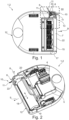
- eine isometrische, teilweise transparente Ansicht des Staubsaugers,
Figur 3- eine vergrößerte Ansicht des in
Figur 1 mit III bezeichneten Bereichs, Figur 4- einen Schnitt durch den Staubsauger im Bereich der Seitenbürste,
Figur 5- eine isometrische Ansicht des Staubsaugers hin zur Seitenbürste bei einem anderen Ausführungsbeispiel,
Figur 6- die
Ansicht aus Figur 4 beim Ausführungsbeispiel derFigur 5
- figure 1
- a top view of an underside of a vacuum cleaner with a side brush,
- figure 2
- an isometric, partially transparent view of the vacuum cleaner,
- figure 3
- an enlarged view of the in
figure 1 area marked III, - figure 4
- a cut through the vacuum cleaner in the area of the side brush,
- figure 5
- an isometric view of the vacuum cleaner towards the side brush in another embodiment,
- figure 6
- the view off
figure 4 in the embodiment offigure 5 .
Ein Staubsauger 1, wie er beispielsweise in den
Das Gehäuse 12 weist eine quer zur Rotationsachse 8 äußerste Außenseite 22 auf. Dabei steht das jeweilige Bürstenbüschel 11 bei Rotation um die Rotationsachse 8 von der Außenseite 22 quer zur Rotationsachse 8 vor.The
Wie insbesondere den
Wie beispielsweise
Der Staubsauger 1 weist, wie insbesondere den
Wie insbesondere
Wie insbesondere den
Beim in den
- 11
- StaubsaugerVacuum cleaner
- 22
- Saugrobotervacuum robot
- 33
- Untergrundunderground
- 44
- Saugeinrichtungsuction device
- 55
- Schmutzbehälterdirt container
- 66
- Seitenbürsteside brush
- 77
- Unterseitebottom
- 88th
- Rotationsachseaxis of rotation
- 99
- Fahrtrichtungdriving direction
- 1010
- Eckbereichcorner area
- 1111
- Bürstenbüschelbrush tuft
- 1212
- GehäuseHousing
- 1313
- Seitensaugmundside suction mouth
- 1414
- Nebenströmungspfadbypass flow path
- 1515
- Hauptsaugmundmain suction mouth
- 1616
- Hauptströmungspfadmain flow path
- 1717
- Bürstenwalzebrush roller
- 1818
- Rollachseroll axis
- 1919
- Hauptzuführkanalmain feed channel
- 2020
- Nebenzuführkanalauxiliary feed channel
- 2121
- Begrenzungsborstenboundary bristles
- 2222
- Außenseiteoutside
Claims (10)
Applications Claiming Priority (1)
| Application Number | Priority Date | Filing Date | Title |
|---|---|---|---|
| DE102021211189.0A DE102021211189A1 (en) | 2021-10-05 | 2021-10-05 | Vacuum cleaner with side brush |
Publications (2)
| Publication Number | Publication Date |
|---|---|
| EP4162852A2 true EP4162852A2 (en) | 2023-04-12 |
| EP4162852A3 EP4162852A3 (en) | 2023-04-26 |
Family
ID=83232636
Family Applications (1)
| Application Number | Title | Priority Date | Filing Date |
|---|---|---|---|
| EP22194617.1A Pending EP4162852A3 (en) | 2021-10-05 | 2022-09-08 | Vacuum cleaner with side brush |
Country Status (2)
| Country | Link |
|---|---|
| EP (1) | EP4162852A3 (en) |
| DE (1) | DE102021211189A1 (en) |
Citations (6)
| Publication number | Priority date | Publication date | Assignee | Title |
|---|---|---|---|---|
| DE102007060750A1 (en) | 2007-12-17 | 2009-06-25 | Vorwerk & Co. Interholding Gmbh | Household vacuum cleaner for cleaning hard floors comprises a brush which is displaced in a position relative to the outer contour while maintaining its horizontal extension |
| EP2561783A2 (en) | 2011-08-23 | 2013-02-27 | Bissell Homecare, Inc. | Auxiliary suction nozzle and port for vacuum cleaner |
| JP2013233305A (en) | 2012-05-09 | 2013-11-21 | Mitsubishi Electric Corp | Self-propelled vacuum cleaner |
| EP2891442A2 (en) | 2014-01-06 | 2015-07-08 | Samsung Electronics Co., Ltd | Robot cleaner and control method thereof |
| DE102015114775A1 (en) | 2015-09-03 | 2017-03-09 | Wessel-Werk Gmbh | robotic vacuum |
| DE102016110817A1 (en) | 2016-06-13 | 2017-12-14 | Wessel-Werk Gmbh | Suction robot with side suction pipes |
Family Cites Families (3)
| Publication number | Priority date | Publication date | Assignee | Title |
|---|---|---|---|---|
| US10729297B2 (en) * | 2014-09-08 | 2020-08-04 | Aktiebolaget Electrolux | Robotic vacuum cleaner |
| US10568483B2 (en) * | 2014-12-12 | 2020-02-25 | Irobot Corporation | Cleaning system for autonomous robot |
| DE102018111845A1 (en) * | 2018-05-17 | 2019-11-21 | Miele & Cie. Kg | Land maintenance equipment |
-
2021
- 2021-10-05 DE DE102021211189.0A patent/DE102021211189A1/en active Pending
-
2022
- 2022-09-08 EP EP22194617.1A patent/EP4162852A3/en active Pending
Patent Citations (6)
| Publication number | Priority date | Publication date | Assignee | Title |
|---|---|---|---|---|
| DE102007060750A1 (en) | 2007-12-17 | 2009-06-25 | Vorwerk & Co. Interholding Gmbh | Household vacuum cleaner for cleaning hard floors comprises a brush which is displaced in a position relative to the outer contour while maintaining its horizontal extension |
| EP2561783A2 (en) | 2011-08-23 | 2013-02-27 | Bissell Homecare, Inc. | Auxiliary suction nozzle and port for vacuum cleaner |
| JP2013233305A (en) | 2012-05-09 | 2013-11-21 | Mitsubishi Electric Corp | Self-propelled vacuum cleaner |
| EP2891442A2 (en) | 2014-01-06 | 2015-07-08 | Samsung Electronics Co., Ltd | Robot cleaner and control method thereof |
| DE102015114775A1 (en) | 2015-09-03 | 2017-03-09 | Wessel-Werk Gmbh | robotic vacuum |
| DE102016110817A1 (en) | 2016-06-13 | 2017-12-14 | Wessel-Werk Gmbh | Suction robot with side suction pipes |
Also Published As
| Publication number | Publication date |
|---|---|
| DE102021211189A1 (en) | 2023-04-06 |
| EP4162852A3 (en) | 2023-04-26 |
Similar Documents
| Publication | Publication Date | Title |
|---|---|---|
| DE2411471C3 (en) | Floor care machine | |
| EP2893860B1 (en) | Floor cleaning device comprising a driven brush roller | |
| DE102015114775A1 (en) | robotic vacuum | |
| DE102012104706B4 (en) | Suction nozzle with two suction mouths | |
| EP3409165A2 (en) | Support assembly to a robot cleaner | |
| DE102017208963A1 (en) | Corner cleaning module for modular cleaning robots | |
| DE102014111702A1 (en) | Electric carpet brush for cleaning a substrate | |
| DE102013106996B4 (en) | Waggon cleaning system | |
| DE1252870C2 (en) | DRIVING CLEANING DEVICE FOR THE REMOVAL OF THE GASER FLIGHT, etc. OF MACHINE PARTS AND THE FLOOR IN TEXTILE MACHINE SHELVES | |
| DE102015108052B4 (en) | Suction nozzle for the collection of coarse and fine dust | |
| EP4162852A2 (en) | Vacuum cleaner with side brush | |
| DE102018111845A1 (en) | Land maintenance equipment | |
| DE102014103686A1 (en) | Floor care device with a front and a rear suction mouth | |
| DE102008030707A1 (en) | Vacuum cleaner dust collection chamber has an opening at the base in front of the filter, for dust removal, activated on diversion of the flow from the normal outflow | |
| DE102015114265A1 (en) | Vacuum robot and method for cleaning a floor surface | |
| DE10208507B4 (en) | Device for cleaning conductor rails | |
| DE1903416A1 (en) | Carpet and floor cleaning device | |
| EP3222186A1 (en) | Vacuum robot | |
| DE3830847C2 (en) | Mobile floor cleaning device | |
| DE3602926A1 (en) | Suction nozzle | |
| EP0565780B1 (en) | Cleaning device for textile machines | |
| DE102021211191B4 (en) | Vacuum cleaner with side brush | |
| DE10241491B4 (en) | Floor nozzle for vacuum cleaner | |
| DE102019116294A1 (en) | Self-cleaning floor cleaning machine | |
| EP3808241B1 (en) | Vacuum cleaning robot for autonomous cleaning of floor surfaces of a room |
Legal Events
| Date | Code | Title | Description |
|---|---|---|---|
| PUAI | Public reference made under article 153(3) epc to a published international application that has entered the european phase |
Free format text: ORIGINAL CODE: 0009012 |
|
| STAA | Information on the status of an ep patent application or granted ep patent |
Free format text: STATUS: THE APPLICATION HAS BEEN PUBLISHED |
|
| PUAL | Search report despatched |
Free format text: ORIGINAL CODE: 0009013 |
|
| AK | Designated contracting states |
Kind code of ref document: A2 Designated state(s): AL AT BE BG CH CY CZ DE DK EE ES FI FR GB GR HR HU IE IS IT LI LT LU LV MC MK MT NL NO PL PT RO RS SE SI SK SM TR |
|
| AK | Designated contracting states |
Kind code of ref document: A3 Designated state(s): AL AT BE BG CH CY CZ DE DK EE ES FI FR GB GR HR HU IE IS IT LI LT LU LV MC MK MT NL NO PL PT RO RS SE SI SK SM TR |
|
| RIC1 | Information provided on ipc code assigned before grant |
Ipc: A47L 9/06 20060101ALI20230323BHEP Ipc: A47L 9/04 20060101AFI20230323BHEP |
|
| STAA | Information on the status of an ep patent application or granted ep patent |
Free format text: STATUS: REQUEST FOR EXAMINATION WAS MADE |
|
| 17P | Request for examination filed |
Effective date: 20231026 |
|
| RBV | Designated contracting states (corrected) |
Designated state(s): AL AT BE BG CH CY CZ DE DK EE ES FI FR GB GR HR HU IE IS IT LI LT LU LV MC MK MT NL NO PL PT RO RS SE SI SK SM TR |