EP4162209B1 - System zum erwärmen einer flüssigkeit mit einem hocheffizienten heizer und einem optimierer - Google Patents
System zum erwärmen einer flüssigkeit mit einem hocheffizienten heizer und einem optimierer Download PDFInfo
- Publication number
- EP4162209B1 EP4162209B1 EP21736693.9A EP21736693A EP4162209B1 EP 4162209 B1 EP4162209 B1 EP 4162209B1 EP 21736693 A EP21736693 A EP 21736693A EP 4162209 B1 EP4162209 B1 EP 4162209B1
- Authority
- EP
- European Patent Office
- Prior art keywords
- liquid
- optimizer
- hydrosonic
- pump
- heating
- Prior art date
- Legal status (The legal status is an assumption and is not a legal conclusion. Google has not performed a legal analysis and makes no representation as to the accuracy of the status listed.)
- Active
Links
Images

Classifications
-
- F—MECHANICAL ENGINEERING; LIGHTING; HEATING; WEAPONS; BLASTING
- F24—HEATING; RANGES; VENTILATING
- F24D—DOMESTIC- OR SPACE-HEATING SYSTEMS, e.g. CENTRAL HEATING SYSTEMS; DOMESTIC HOT-WATER SUPPLY SYSTEMS; ELEMENTS OR COMPONENTS THEREFOR
- F24D15/00—Other domestic- or space-heating systems
- F24D15/02—Other domestic- or space-heating systems consisting of self-contained heating units, e.g. storage heaters
-
- F—MECHANICAL ENGINEERING; LIGHTING; HEATING; WEAPONS; BLASTING
- F22—STEAM GENERATION
- F22B—METHODS OF STEAM GENERATION; STEAM BOILERS
- F22B3/00—Other methods of steam generation; Steam boilers not provided for in other groups of this subclass
- F22B3/06—Other methods of steam generation; Steam boilers not provided for in other groups of this subclass by transformation of mechanical, e.g. kinetic, energy into heat energy
-
- F—MECHANICAL ENGINEERING; LIGHTING; HEATING; WEAPONS; BLASTING
- F24—HEATING; RANGES; VENTILATING
- F24V—COLLECTION, PRODUCTION OR USE OF HEAT NOT OTHERWISE PROVIDED FOR
- F24V99/00—Subject matter not provided for in other main groups of this subclass
-
- F—MECHANICAL ENGINEERING; LIGHTING; HEATING; WEAPONS; BLASTING
- F24—HEATING; RANGES; VENTILATING
- F24D—DOMESTIC- OR SPACE-HEATING SYSTEMS, e.g. CENTRAL HEATING SYSTEMS; DOMESTIC HOT-WATER SUPPLY SYSTEMS; ELEMENTS OR COMPONENTS THEREFOR
- F24D2200/00—Heat sources or energy sources
- F24D2200/16—Waste heat
- F24D2200/30—Friction
Definitions
- the present invention is an innovative system for liquid heating, especially for the production of domestic hot water and/or for heating, for household and/or industrial use.
- the object of the present invention is an innovative system for liquid heating based on the so-called “cavitation principle” with a high efficiency and energy performance.
- the invention is included in the field of devices and systems for heating fluids, and in particular liquids.
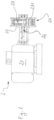
- the present invention is applicable within the field of devices using rotating elements to generate heat in the liquid passing through them, such as the so-called “hydrosonic pumps”, also known as “hydrothermal turbine systems”, schematically shown in the example in Fig. 1 .
- the aforementioned pumps 2 which can be crossed by a liquid to be heated, and generally water, include a perforated cylindrical "rotor” 23, i.e. equipped with a plurality of cavities 231, assembled with a rotation shaft 24, and a "stator" 22 within the mentioned rotor 23, the stator is able to rotate at high speed driven by an electric motor 21 (e.g. three-phase and powered indifferently by electric, solar, wind, pneumatic energy, etc.), it is connected and works together in a known procedure with said shaft 24.
- an electric motor 21 e.g. three-phase and powered indifferently by electric, solar, wind, pneumatic energy, etc.
- the stator 22 is also a cylindrical body which includes a crimped inner surface and a pair of metal discs/covers 25 and 26 for the airtightly closing of its ends (from now on “end plates” or “closing flanges" 25, 26).
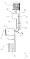
- a specific pipe system connects the abovementioned hydrosonic pump 2 to a primary circuit 3, and in particular to at least one of its liquid storage 30, for the production of domestic hot water and/or to a secondary circuit 4 which includes, for example, a heat exchange unit to heat up a room (see fig. 2 ).
- liquid storage 30 may be implemented to the level of the heat exchange unit, for example a plate unit or a coil unit.
- a prior art document disclosing a system for heating water for domestic purposes based on a cavitation turbine is KR 2011 0032112 A .
- the heating of the cited hydrosonic pumps is achieved thanks to the very high turbulence of the liquid caused by the particular geometric and structural conformation of the rotor 23, and by its cooperation with the stator 22.
- these hydrosonic pumps 2 are able to achieve a much higher efficiency than the traditional thermal generators, the ones generally used for the production of domestic hot water and/or for space heating (e.g., common household boilers).
- This mode during the initial process of activation of the hydrosonic pump 2 (i.e. before reaching full operation), has a series of heating phases of the liquid, each phase is bound to another; in particular, during the first phase, the hydrosonic pump 2 is activated for a first rapid heating of the liquid loaded in it, moreover, during this phase, the circulation towards the primary circuit 3 is locked, as well as a subsequent phase where is passed between the hydrosonic pump 2 and the storage 30 of the primary circuit 3, once this has reached the desired temperature (see fig. 2 ).
- the results may also reflect an increase of the operating costs of the system itself.
- the aim of the present invention is to delete the disadvantages of the known technique listed above, through an innovative system for liquid heating, and preferably for the production of domestic hot water and/or for space heating, and capable of achieving and ensuring maximum efficiency and energy performance quickly and in a simple and reliable manner.
- any dimensional and spatial word refers, unless it is differently specified, to the correct setting of the invention, as indicated in the drawings, and it does not necessarily correspond with the setting of the invention during working conditions.
- 1 represents the system for liquid heating, and preferably for producing domestic hot water and/or for space heating.
- FIG. 1 particularly shows:
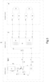
- the system 1 of the present invention may further include a secondary circuit 4 (see Fig. 3 ) to dissipate heat generated in said hydrosonic pump 2 and transmitted to the liquid flowing through it, and to the said secondary circuit 4 which it works with and/or connected to the primary circuit 3.
- a secondary circuit 4 see Fig. 3
- both the hydrosonic pump 2 and the optimizer 5 may also be referred to as "high efficiency cavitation boiler".
- the above-mentioned cavitation boiler may further include an expansion vase (which is not shown in the attached figures) which, as is well known, has the function of containing the volume increase of the liquid heating and the resulting pressure variations, it also avoids pressure surges and water hammer, otherwise they would be absorbed, by the system, and cause a potential damage.
- an expansion vase which is not shown in the attached figures
- the circulation of the liquid between the optimizer 5 and the primary circuit 3 can be ensured by at least one first pump 33 and its flow rate regulated by at least one suitable solenoid valve 34.
- the abovementioned solenoid valve 34 is able to interrupt and/or re-establish, in accordance with the detected temperature, the circulation of the liquid from the optimizer 5 towards the abovementioned primary circuit 3, and it is able to set its circulation temperature.
- the solenoid valve 34 is linked to sensors and/or temperature probes 35 which are placed in correspondence with the hydrosonic pump 2 within the internal circuit 501 and along the outflow pipe 51 from the optimizer 5.
- At least one solenoid valve 34 is placed along the flow line 31 of the primary circuit 3.
- a second circulation pump may also be provided within the cavitation boiler, it can ease liquid's flow to be heated between its cavitational turbine 20 and the optimizer 5.
- the circulation within the cavitation boiler may take place directly through natural flow, without the aid of mechanical pushing devices.
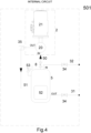
- a flow disconnector 8 see fig. 3 , and fig. 4 , (also named disconnecting valve, analogous to the one of the prior art indicated with reference 36 in fig. 2 ) allows regulation of flow and in particular the flow rates.
- the secondary circuit 4 has the function of dissipating heat generated by the high efficiency cavitation boiler, it consists of:
- At least one circulation pump which ensures the flow of the abovementioned liquid within the secondary circuit 4.
- the cavitation boiler of the invention achieves its maximum energy performance and efficiency when the temperature of the liquid, which goes into the turbine 20 of the hydrosonic pump 2 to be heated, has a temperature "not far” (with reference to the amount of the circulating flow) from the one of the same liquid when it is heated and exits the hydrosonic pump 2. Under such conditions, the hydrosonic pump 2 does not suffer any thermal "shock", and thus avoids any possible slowdowns or unfavourable conditions for liquid heating.
- the cavitation boiler of the invention reaches maximum operating efficiency when the differential (or gradient) between the inlet and outlet temperatures of the liquid in/from the turbine 20 of the hydrosonic pump 2 is kept constant and equal to a value defined from now on as ⁇ Tideal.
- the abovementioned inertial storage is therefore a "small" storage, it corresponds with the optimizer 5 mentioned above.
- the optimizer 5 is arranged to allow the cavitation boiler (and in particular its cavitation turbine 20) to exchange heat with the primary circuit 3 and/or with the secondary circuit 4 without substantial variations of the abovementioned gradient ⁇ Tideal (which is kept constant).
- the ⁇ Tideal is the gradient that ensures the maximum efficiency of the hydrosonic pump 2, it can be advantageously chosen as a fixed and optimal threshold, it can be set through probes or thermostats.
- the aforesaid solenoid valve 34 "manages" the flow of the liquid, between the optimizer 5 and the primary circuit 3, as follows:
- the abovementioned optimizer 5 works in order to keep the ⁇ Toptimizer, on operating conditions, equal to ⁇ Tideal.
- the abovementioned optimizer 5 is a device able to work between a first and a second operating temperature, wherein:
- the first operating temperature is lower than the second operating temperature, indeed their gap defines the abovementioned ⁇ Toptimizer.
- the aforementioned optimizer 5 has a storage tank 52 with a lowered volume, but it is resistant to high pressures in order to allow a swift or a sudden heating.
- the aforementioned optimizer 5 has a capacity intermediate the traditional storages for liquids (generally the tanks have different volumes and they start from 20 - 30 litres, moreover they do not operate at high operating pressure) and a hydraulic compensator (it is well known to the skilled in the art and with a maximum volume between 2 - 3 litres, but it withstands at high operating pressure).
- the optimizer 5 is thermally insulated in order to reduce the unavoidable heat losses of the liquid processed and contained within it; in other words, the insulation is able to reduce heat losses when the hydrosonic pump 2 stalls, it preserves high temperatures inside the tank 52 even for many consecutive hours.
- the tank 52 of the abovementioned optimizer 5 has a volume between 7 and 15 litres and it is able to withstand pressures of even more than 20 bar.
- the tank 52 ideally, has two inlets within the aforementioned pipes 50, 32 for the supply and return flow, and specifically from the hydrosonic pump 2 and from the primary circuit 3, and two outlets within the pipes 31, 51 for the supply and return flow, and specifically from the primary circuit 3 and from the same hydrosonic pump 2.
- reference 53 in Fig. 3 identifies a typical and automatic air escape valve (also known as a wild card valve) from the suppy 52 of the optimizer 5.
- the hydrosonic pump 2, its motor 21 and the optimizer 5 can be settled and placed side by side or stacked vertically on several levels on a frame (also known as a chassis or the housing of the cavity boiler).
- a frame also known as a chassis or the housing of the cavity boiler.
- the abovementioned chassis may also fit a control panel and a screen for the setting, as well as managing and displaying the other working and functional parameters of the system 1 of the invention and the related boiler.
- the secondary circuit 4 for heat dispersion (as already discussed, the aforesaid radiators and/or exchangers inside the storage 30, etc.), can exchange heat with the storage tank 30, once the right temperature for the room "served” thereby has been reached, the secondary circuit will control the switching off or the stand-by of the high-efficiency cavitation boiler, through a special and specific thermostat, until the gradient ⁇ Toptimizer and the ⁇ Tideal have substantially the same value.
- the scheme 1 of the invention is able to supply it immediately, due to the fact that the ⁇ Toptimizer has remained steady and equal to ⁇ Tideal.
- the liquid heating which can be used for hygienic purposes and/or for room heating, has a gradient ⁇ Tideal and a temperature at the inlet and the outlet from/to the abovementioned hydrosonic pump 2 which is substantially steady, so the ideally temperature is:
- the system for liquid heating especially for the production of domestic hot water and/or for heating, and the relative method for optimising its energy performance and efficiency, have achieved its targets; in particular, it is possible to ensure high efficiency and performance by using mechanical components which have the following characteristics: they are simple to construct, economical and highly reliable; all this in a quick, easy and reliable manner.
- system 1 of the invention is suitable for many other purposes; in fact, as well as its application for the production of domestic hot water for civil or industrial use and for space heating, it can be used, as a non exhaustive examples, for climatization, for the supply of hot water in household appliances (e.g., washing machines and dishwashers), for the supply of industrial machines (e.g., hot printing machines, and other), and heat pumps, etc.
- household appliances e.g., washing machines and dishwashers
- industrial machines e.g., hot printing machines, and other
- heat pumps etc.
Landscapes
- Engineering & Computer Science (AREA)
- General Engineering & Computer Science (AREA)
- Physics & Mathematics (AREA)
- Thermal Sciences (AREA)
- Mechanical Engineering (AREA)
- Chemical & Material Sciences (AREA)
- Combustion & Propulsion (AREA)
- Chemical Kinetics & Catalysis (AREA)
- Instantaneous Water Boilers, Portable Hot-Water Supply Apparatuses, And Control Of Portable Hot-Water Supply Apparatuses (AREA)
- Heat-Pump Type And Storage Water Heaters (AREA)
- Steam Or Hot-Water Central Heating Systems (AREA)
- Control Of Steam Boilers And Waste-Gas Boilers (AREA)
- Central Heating Systems (AREA)
- Engine Equipment That Uses Special Cycles (AREA)
Claims (10)
- System (1) zum Erwärmen einer Flüssigkeit, wobei das System (1) zumindest Folgendes umfasst:- eine Hydroschallpumpe (2) zum Erwärmen der Flüssigkeit,- einen primären Kreislauf (3), der mindestens Folgendes umfasst:- einen Speicher (30) der Flüssigkeit oder eine Wärmetauschereinheit (45),- mehrere Rohre (31, 32) zur Verbindung des Speichers (30) oder der Wärmetauschereinheit (45) mit der Hydroschallpumpe (2),- mindestens ein Magnetventil (34), um die Flüssigkeitszirkulation innerhalb des primären Kreislaufs (3) zu öffnen und/oder zu schließen, und- einen Optimierer (5), der mit der Hydroschallpumpe (2) verbunden und dieser nachgelagert angeordnet ist, wobei die Verbindung zwischen der Hydroschallpumpe (2) und dem Optimierer (5) durch einen inneren Kreislauf (501) sichergestellt ist, der ein Druckrohr (51) und ein Rücklaufrohr (50) umfasst;wobei der Optimierer (5) zumindest mit dem primären Kreislauf (3) kommuniziert, um diesem die von der Hydroschallpumpe (2) erzeugte Wärmeenergie zu geben und zu übertragen, wobei der Optimierer (5) einen Speichertank (52) umfasst:- mit verringertem Volumen, zwischen dem Volumen eines gewöhnlichen Flüssigkeitsspeichers und eines Hydraulikkompensators;- der hohem Druck standhalten und dabei arbeiten kann;- der wärmeisoliert ist,dadurch gekennzeichnet, dass der Optimierer (5) mindestens ein Strangventil (8) umfasst, das dazu ausgelegt ist, die Strömungsgeschwindigkeit der in der Hydroschallpumpe (2) zirkulierenden Flüssigkeit zu steuern, innerhalb des inneren Kreislaufs (501) vorzugsweise entlang des Rücklaufrohrs (50) des Optimierers (5) platziert ist, einen Temperaturverlauf ΔTOptimierer zwischen einer Einlass- und Auslassflüssigkeit gleich einem Temperaturverlaufschwellenwert ΔTideal zwischen der Einlass- und Auslasstemperatur der Hydroschallpumpe (2) betreibt und gewährleistet, um maximale Effizienz und energetische Leistung zu ermöglichen.
- System (1) zum Erwärmen einer Flüssigkeit nach Anspruch 1, dadurch gekennzeichnet, dass das mindestens eine Magnetventil (34) dazu ausgelegt ist, die Flüssigkeitsströmung vom Optimierer (5) zum primären Kreislauf (3) zu stoppen und/oder wieder aufzubauen, wobei das Magnetventil (34) dazu angeordnet ist, mit Sensoren und/oder Temperatursonden (35) verbunden zu sein, die in dem inneren Kreislaufs (501) und vorzugsweise entlang des Rücklaufrohrs (50) oder des Druckrohrs (51) des Optimierers (5) platziert sind.
- System (1) zum Erwärmen einer Flüssigkeit nach dem vorstehenden Anspruch, dadurch gekennzeichnet, dass sich das mindestens eine Magnetventil (34) entlang einer Ablaufleitung (31) oder einer Rücklaufleitung (32) der mehreren Rohre (31, 32) des primären Kreislaufs (3) befindet.
- System (1) zum Erwärmen einer Flüssigkeit nach Anspruch 1, dadurch gekennzeichnet, dass es ferner einen zusätzlichen sekundären Kreislauf (4) zum Ableiten von in der Hydroschallpumpe (2) erzeugter und auf die Flüssigkeit übertragener Wärme umfasst, wobei der sekundäre Kreislauf (4) mit dem primären Kreislauf (3) zusammenwirkt und/oder damit verbunden ist.
- System (1) zum Erwärmen einer Flüssigkeit nach dem vorstehenden Anspruch, dadurch gekennzeichnet, dass der sekundäre Kreislauf (4) mindestens Folgendes umfasst:- eine Wärmetauschereinheit (40), die mindestens einen Radiator (40) umfasst, und/oder- einen oder mehrere Rohrschlangenwärmetauscher (30), der/die innerhalb des primären Kreislaufs (3) platziert ist/sind, und/oder- Direktversorgungsvorrichtungen.
- System (1) zum Erwärmen einer Flüssigkeit nach einem der vorstehenden Ansprüche, dadurch gekennzeichnet, dass es ferner ein zusätzliches Dehnungsgefäß umfasst.
- System (1) zum Erwärmen einer Flüssigkeit nach einem der vorstehenden Ansprüche, dadurch gekennzeichnet, dass es eine oder mehrere Umwälzpumpen (33) innerhalb des primären (3) und sekundären (4) Kreislaufs umfasst.
- System (1) zum Erwärmen einer Flüssigkeit nach einem der vorstehenden Ansprüche, dadurch gekennzeichnet, dass der Sammelbehälter (52) des Optimierers (5) ein Fassungsvermögen im Bereich von 7 bis 15 Liter aufweist und dazu funktionsfähig ist, Drücken von mehr als 20 bar standzuhalten.
- System (1) zum Erwärmen einer Flüssigkeit nach einem der vorstehenden Ansprüche, dadurch gekennzeichnet, dass:- eine Kavitationsturbine (20) der Hydroschallpumpe (2) die Strömungsgeschwindigkeit der zirkulierenden Flüssigkeit regelt, die vom Strangventil (8) konstant zwischen 200 und 300 Liter/h gehalten wird,wobei:die Strömungsgeschwindigkeit mit einem Temperaturverlaufschwellenwert ΔTideal von etwa 30 °C bezüglich einer Auslass-/Ausströmtemperatur von etwa 130 °C und einer Rücklauftemperatur innerhalb der Turbine (20) von etwa 100 °C fortfährt;andernfalls die Strömungsgeschwindigkeit mit einem Temperaturverlaufschwellenwert ΔTideal von etwa 35 °C bezüglich einer Auslass-/Ausströmtemperatur von etwa 145 °C und einer Rücklauftemperatur innerhalb der Turbine (20) von etwa 110 °C fortfährt.
- System (1) zum Erwärmen einer Flüssigkeit nach einem der vorstehenden Ansprüche, dadurch gekennzeichnet, dass zumindest die Hydroschallpumpe (2), ihr Motor (21) und der Optimierer (5) auf mehreren Ebenen und auf einem Rahmen oder Chassis vertikal gestapelt angeordnet und montiert sind.
Applications Claiming Priority (2)
| Application Number | Priority Date | Filing Date | Title |
|---|---|---|---|
| IT102020000013645A IT202000013645A1 (it) | 2020-06-08 | 2020-06-08 | Sistema per il riscaldamento di un liquido comprendente una caldaia ad alto rendimento ed un ottimizzatore |
| PCT/IB2021/054976 WO2021250543A1 (en) | 2020-06-08 | 2021-06-07 | System for heating a liquid including a high-efficiency heater and an optimizer |
Publications (3)
| Publication Number | Publication Date |
|---|---|
| EP4162209A1 EP4162209A1 (de) | 2023-04-12 |
| EP4162209C0 EP4162209C0 (de) | 2024-08-21 |
| EP4162209B1 true EP4162209B1 (de) | 2024-08-21 |
Family
ID=72266684
Family Applications (1)
| Application Number | Title | Priority Date | Filing Date |
|---|---|---|---|
| EP21736693.9A Active EP4162209B1 (de) | 2020-06-08 | 2021-06-07 | System zum erwärmen einer flüssigkeit mit einem hocheffizienten heizer und einem optimierer |
Country Status (7)
| Country | Link |
|---|---|
| US (1) | US12215875B2 (de) |
| EP (1) | EP4162209B1 (de) |
| CA (1) | CA3185679A1 (de) |
| ES (1) | ES2995982T3 (de) |
| IT (1) | IT202000013645A1 (de) |
| PL (1) | PL4162209T3 (de) |
| WO (1) | WO2021250543A1 (de) |
Families Citing this family (2)
| Publication number | Priority date | Publication date | Assignee | Title |
|---|---|---|---|---|
| IT202300022170A1 (it) * | 2023-10-23 | 2025-04-23 | Snf Envirotech Srl | Impianto e metodo di riscaldamento di acqua |
| EP4603682A1 (de) * | 2024-02-13 | 2025-08-20 | Staubert, Adolf | System zur nutzung von wärmeenergie |
Family Cites Families (9)
| Publication number | Priority date | Publication date | Assignee | Title |
|---|---|---|---|---|
| FR1419764A (fr) * | 1964-10-19 | 1965-12-03 | Installation de chauffage dont la source de chaleur est constituée par le laminage d'un débit de liquide sous pression | |
| US4372254A (en) * | 1981-01-23 | 1983-02-08 | Edmund Hildebrandt | Hydraulic heat generator |
| US5188090A (en) | 1991-04-08 | 1993-02-23 | Hydro Dynamics, Inc. | Apparatus for heating fluids |
| DE19535062C1 (de) * | 1995-09-21 | 1997-04-17 | Hy Tec Gmbh | Vorrichtung zur Umwandlung einer Energie in eine andere Energieform bzw. in Nutzwärme |
| FR2928442B1 (fr) | 2008-03-06 | 2010-12-17 | Mer Joseph Le | Installation de production d'eau chaude sanitaire |
| KR20110032112A (ko) * | 2009-09-22 | 2011-03-30 | (주)현대이티에스 | 유체마찰가열 회로시스템 |
| US20140290952A1 (en) * | 2010-08-31 | 2014-10-02 | Rusty Lamb | Flameless Heating Method |
| KR101246922B1 (ko) * | 2011-08-05 | 2013-03-25 | 권영중 | 마찰히터를 이용한 급탕 및 난방 시스템 |
| JP2014129978A (ja) * | 2012-12-28 | 2014-07-10 | Kanto Natural Gas Development Co Ltd | 熱交換器の防汚処理方法および防汚処理システム |
-
2020
- 2020-06-08 IT IT102020000013645A patent/IT202000013645A1/it unknown
-
2021
- 2021-06-07 EP EP21736693.9A patent/EP4162209B1/de active Active
- 2021-06-07 US US18/008,335 patent/US12215875B2/en active Active
- 2021-06-07 PL PL21736693.9T patent/PL4162209T3/pl unknown
- 2021-06-07 ES ES21736693T patent/ES2995982T3/es active Active
- 2021-06-07 CA CA3185679A patent/CA3185679A1/en active Pending
- 2021-06-07 WO PCT/IB2021/054976 patent/WO2021250543A1/en not_active Ceased
Also Published As
| Publication number | Publication date |
|---|---|
| US20230204224A1 (en) | 2023-06-29 |
| EP4162209C0 (de) | 2024-08-21 |
| PL4162209T3 (pl) | 2024-12-02 |
| CA3185679A1 (en) | 2021-12-16 |
| WO2021250543A1 (en) | 2021-12-16 |
| CN115667806A (zh) | 2023-01-31 |
| US12215875B2 (en) | 2025-02-04 |
| EP4162209A1 (de) | 2023-04-12 |
| IT202000013645A1 (it) | 2021-12-08 |
| ES2995982T3 (en) | 2025-03-19 |
Similar Documents
| Publication | Publication Date | Title |
|---|---|---|
| JP5012695B2 (ja) | 給湯システム | |
| KR102221181B1 (ko) | 에너지 저장 시스템 | |
| EP4162209B1 (de) | System zum erwärmen einer flüssigkeit mit einem hocheffizienten heizer und einem optimierer | |
| JP6072682B2 (ja) | ヒート・ポンプ・システム | |
| CN206816470U (zh) | 一种空压机余热回收装置 | |
| US20110048404A1 (en) | Heating system | |
| NO143511B (no) | Varmepumpeanlegg. | |
| JP4971838B2 (ja) | 給湯装置および給湯暖房装置 | |
| CN108954456A (zh) | 一种太阳能供暖系统及其供暖方法 | |
| RU2834716C1 (ru) | Система нагрева жидкости, включающая в себя высокоэффективный нагреватель и устройство оптимизации | |
| WO2016042312A1 (en) | A domestic water and space heating system | |
| CN115667806B (en) | System for heating a liquid comprising an efficient heater and an optimizer | |
| WO2021053357A1 (en) | Thermal storage tank for heat pump system | |
| CA2560585A1 (en) | Hot water supply device | |
| KR101024489B1 (ko) | 에너지 절약형 전기보일러 | |
| JP5887230B2 (ja) | 貯湯式給湯機 | |
| KR100926015B1 (ko) | 저탕식 보일러 | |
| CN209415552U (zh) | 一种太阳能供暖系统 | |
| WO2020079460A1 (en) | Fluid circulating heating apparatus | |
| RU2758658C2 (ru) | Система аккумуляторного электроотопления | |
| JP6819815B2 (ja) | 貯湯式給湯機 | |
| JP6700070B2 (ja) | 水対蒸気熱交換システムおよびその運転方法 | |
| WO2024023513A1 (en) | Hot water supply system | |
| JP6148186B2 (ja) | 貯湯式ヒートポンプ給湯装置 | |
| GB2254407A (en) | Domestic hot water heating apparatus |
Legal Events
| Date | Code | Title | Description |
|---|---|---|---|
| STAA | Information on the status of an ep patent application or granted ep patent |
Free format text: STATUS: UNKNOWN |
|
| STAA | Information on the status of an ep patent application or granted ep patent |
Free format text: STATUS: THE INTERNATIONAL PUBLICATION HAS BEEN MADE |
|
| PUAI | Public reference made under article 153(3) epc to a published international application that has entered the european phase |
Free format text: ORIGINAL CODE: 0009012 |
|
| STAA | Information on the status of an ep patent application or granted ep patent |
Free format text: STATUS: REQUEST FOR EXAMINATION WAS MADE |
|
| 17P | Request for examination filed |
Effective date: 20221129 |
|
| AK | Designated contracting states |
Kind code of ref document: A1 Designated state(s): AL AT BE BG CH CY CZ DE DK EE ES FI FR GB GR HR HU IE IS IT LI LT LU LV MC MK MT NL NO PL PT RO RS SE SI SK SM TR |
|
| DAV | Request for validation of the european patent (deleted) | ||
| DAX | Request for extension of the european patent (deleted) | ||
| GRAP | Despatch of communication of intention to grant a patent |
Free format text: ORIGINAL CODE: EPIDOSNIGR1 |
|
| STAA | Information on the status of an ep patent application or granted ep patent |
Free format text: STATUS: GRANT OF PATENT IS INTENDED |
|
| RIC1 | Information provided on ipc code assigned before grant |
Ipc: F24V 99/00 20180101ALI20240304BHEP Ipc: F24D 15/02 20060101AFI20240304BHEP |
|
| INTG | Intention to grant announced |
Effective date: 20240327 |
|
| GRAS | Grant fee paid |
Free format text: ORIGINAL CODE: EPIDOSNIGR3 |
|
| GRAA | (expected) grant |
Free format text: ORIGINAL CODE: 0009210 |
|
| STAA | Information on the status of an ep patent application or granted ep patent |
Free format text: STATUS: THE PATENT HAS BEEN GRANTED |
|
| AK | Designated contracting states |
Kind code of ref document: B1 Designated state(s): AL AT BE BG CH CY CZ DE DK EE ES FI FR GB GR HR HU IE IS IT LI LT LU LV MC MK MT NL NO PL PT RO RS SE SI SK SM TR |
|
| REG | Reference to a national code |
Ref country code: GB Ref legal event code: FG4D |
|
| REG | Reference to a national code |
Ref country code: CH Ref legal event code: EP |
|
| REG | Reference to a national code |
Ref country code: IE Ref legal event code: FG4D |
|
| REG | Reference to a national code |
Ref country code: DE Ref legal event code: R096 Ref document number: 602021017566 Country of ref document: DE |
|
| U01 | Request for unitary effect filed |
Effective date: 20240918 |
|
| U07 | Unitary effect registered |
Designated state(s): AT BE BG DE DK EE FI FR IT LT LU LV MT NL PT RO SE SI Effective date: 20241010 |
|
| PG25 | Lapsed in a contracting state [announced via postgrant information from national office to epo] |
Ref country code: GR Free format text: LAPSE BECAUSE OF FAILURE TO SUBMIT A TRANSLATION OF THE DESCRIPTION OR TO PAY THE FEE WITHIN THE PRESCRIBED TIME-LIMIT Effective date: 20241122 |
|
| PG25 | Lapsed in a contracting state [announced via postgrant information from national office to epo] |
Ref country code: IS Free format text: LAPSE BECAUSE OF FAILURE TO SUBMIT A TRANSLATION OF THE DESCRIPTION OR TO PAY THE FEE WITHIN THE PRESCRIBED TIME-LIMIT Effective date: 20241221 |
|
| PG25 | Lapsed in a contracting state [announced via postgrant information from national office to epo] |
Ref country code: HR Free format text: LAPSE BECAUSE OF FAILURE TO SUBMIT A TRANSLATION OF THE DESCRIPTION OR TO PAY THE FEE WITHIN THE PRESCRIBED TIME-LIMIT Effective date: 20240821 |
|
| PG25 | Lapsed in a contracting state [announced via postgrant information from national office to epo] |
Ref country code: RS Free format text: LAPSE BECAUSE OF FAILURE TO SUBMIT A TRANSLATION OF THE DESCRIPTION OR TO PAY THE FEE WITHIN THE PRESCRIBED TIME-LIMIT Effective date: 20241121 |
|
| PG25 | Lapsed in a contracting state [announced via postgrant information from national office to epo] |
Ref country code: RS Free format text: LAPSE BECAUSE OF FAILURE TO SUBMIT A TRANSLATION OF THE DESCRIPTION OR TO PAY THE FEE WITHIN THE PRESCRIBED TIME-LIMIT Effective date: 20241121 Ref country code: IS Free format text: LAPSE BECAUSE OF FAILURE TO SUBMIT A TRANSLATION OF THE DESCRIPTION OR TO PAY THE FEE WITHIN THE PRESCRIBED TIME-LIMIT Effective date: 20241221 Ref country code: HR Free format text: LAPSE BECAUSE OF FAILURE TO SUBMIT A TRANSLATION OF THE DESCRIPTION OR TO PAY THE FEE WITHIN THE PRESCRIBED TIME-LIMIT Effective date: 20240821 Ref country code: GR Free format text: LAPSE BECAUSE OF FAILURE TO SUBMIT A TRANSLATION OF THE DESCRIPTION OR TO PAY THE FEE WITHIN THE PRESCRIBED TIME-LIMIT Effective date: 20241122 |
|
| REG | Reference to a national code |
Ref country code: ES Ref legal event code: FG2A Ref document number: 2995982 Country of ref document: ES Kind code of ref document: T3 Effective date: 20250319 |
|
| PG25 | Lapsed in a contracting state [announced via postgrant information from national office to epo] |
Ref country code: SM Free format text: LAPSE BECAUSE OF FAILURE TO SUBMIT A TRANSLATION OF THE DESCRIPTION OR TO PAY THE FEE WITHIN THE PRESCRIBED TIME-LIMIT Effective date: 20240821 |
|
| PG25 | Lapsed in a contracting state [announced via postgrant information from national office to epo] |
Ref country code: CZ Free format text: LAPSE BECAUSE OF FAILURE TO SUBMIT A TRANSLATION OF THE DESCRIPTION OR TO PAY THE FEE WITHIN THE PRESCRIBED TIME-LIMIT Effective date: 20240821 |
|
| PG25 | Lapsed in a contracting state [announced via postgrant information from national office to epo] |
Ref country code: SK Free format text: LAPSE BECAUSE OF FAILURE TO SUBMIT A TRANSLATION OF THE DESCRIPTION OR TO PAY THE FEE WITHIN THE PRESCRIBED TIME-LIMIT Effective date: 20240821 |
|
| PLBE | No opposition filed within time limit |
Free format text: ORIGINAL CODE: 0009261 |
|
| STAA | Information on the status of an ep patent application or granted ep patent |
Free format text: STATUS: NO OPPOSITION FILED WITHIN TIME LIMIT |
|
| PGFP | Annual fee paid to national office [announced via postgrant information from national office to epo] |
Ref country code: PL Payment date: 20250602 Year of fee payment: 5 |
|
| U20 | Renewal fee for the european patent with unitary effect paid |
Year of fee payment: 5 Effective date: 20250603 |
|
| PGFP | Annual fee paid to national office [announced via postgrant information from national office to epo] |
Ref country code: GB Payment date: 20250617 Year of fee payment: 5 |
|
| PGFP | Annual fee paid to national office [announced via postgrant information from national office to epo] |
Ref country code: NO Payment date: 20250617 Year of fee payment: 5 |
|
| PGFP | Annual fee paid to national office [announced via postgrant information from national office to epo] |
Ref country code: IE Payment date: 20250617 Year of fee payment: 5 |
|
| 26N | No opposition filed |
Effective date: 20250522 |
|
| PGFP | Annual fee paid to national office [announced via postgrant information from national office to epo] |
Ref country code: ES Payment date: 20250710 Year of fee payment: 5 |
|
| PGFP | Annual fee paid to national office [announced via postgrant information from national office to epo] |
Ref country code: CH Payment date: 20250701 Year of fee payment: 5 |