EP4161850B1 - Système de stockage pour stocker des piles de panneaux en rangées de stockage, destiné à être utilisé dans des usines de fabrication de panneaux - Google Patents
Système de stockage pour stocker des piles de panneaux en rangées de stockage, destiné à être utilisé dans des usines de fabrication de panneaux Download PDFInfo
- Publication number
- EP4161850B1 EP4161850B1 EP21733722.9A EP21733722A EP4161850B1 EP 4161850 B1 EP4161850 B1 EP 4161850B1 EP 21733722 A EP21733722 A EP 21733722A EP 4161850 B1 EP4161850 B1 EP 4161850B1
- Authority
- EP
- European Patent Office
- Prior art keywords
- glued laminated
- storage system
- laminated beams
- storage
- beams
- Prior art date
- Legal status (The legal status is an assumption and is not a legal conclusion. Google has not performed a legal analysis and makes no representation as to the accuracy of the status listed.)
- Active
Links
- 238000003860 storage Methods 0.000 title claims description 60
- 239000002023 wood Substances 0.000 claims description 16
- 229910000831 Steel Inorganic materials 0.000 claims description 8
- 239000010959 steel Substances 0.000 claims description 8
- 239000002245 particle Substances 0.000 claims description 4
- 239000000463 material Substances 0.000 description 3
- 238000010276 construction Methods 0.000 description 2
- 238000009434 installation Methods 0.000 description 2
- 238000000034 method Methods 0.000 description 2
- 230000032258 transport Effects 0.000 description 2
- 230000007547 defect Effects 0.000 description 1
- 238000011065 in-situ storage Methods 0.000 description 1
- 238000012432 intermediate storage Methods 0.000 description 1
- 230000014759 maintenance of location Effects 0.000 description 1
- 238000004519 manufacturing process Methods 0.000 description 1
- 230000000284 resting effect Effects 0.000 description 1
Images

Classifications
-
- B—PERFORMING OPERATIONS; TRANSPORTING
- B65—CONVEYING; PACKING; STORING; HANDLING THIN OR FILAMENTARY MATERIAL
- B65G—TRANSPORT OR STORAGE DEVICES, e.g. CONVEYORS FOR LOADING OR TIPPING, SHOP CONVEYOR SYSTEMS OR PNEUMATIC TUBE CONVEYORS
- B65G47/00—Article or material-handling devices associated with conveyors; Methods employing such devices
- B65G47/52—Devices for transferring articles or materials between conveyors i.e. discharging or feeding devices
- B65G47/53—Devices for transferring articles or materials between conveyors i.e. discharging or feeding devices between conveyors which cross one another
-
- B—PERFORMING OPERATIONS; TRANSPORTING
- B65—CONVEYING; PACKING; STORING; HANDLING THIN OR FILAMENTARY MATERIAL
- B65G—TRANSPORT OR STORAGE DEVICES, e.g. CONVEYORS FOR LOADING OR TIPPING, SHOP CONVEYOR SYSTEMS OR PNEUMATIC TUBE CONVEYORS
- B65G1/00—Storing articles, individually or in orderly arrangement, in warehouses or magazines
- B65G1/02—Storage devices
- B65G1/04—Storage devices mechanical
- B65G1/06—Storage devices mechanical with means for presenting articles for removal at predetermined position or level
- B65G1/065—Storage devices mechanical with means for presenting articles for removal at predetermined position or level with self propelled cars
-
- B—PERFORMING OPERATIONS; TRANSPORTING
- B65—CONVEYING; PACKING; STORING; HANDLING THIN OR FILAMENTARY MATERIAL
- B65G—TRANSPORT OR STORAGE DEVICES, e.g. CONVEYORS FOR LOADING OR TIPPING, SHOP CONVEYOR SYSTEMS OR PNEUMATIC TUBE CONVEYORS
- B65G1/00—Storing articles, individually or in orderly arrangement, in warehouses or magazines
- B65G1/02—Storage devices
- B65G1/04—Storage devices mechanical
- B65G1/0407—Storage devices mechanical using stacker cranes
- B65G1/0414—Storage devices mechanical using stacker cranes provided with satellite cars adapted to travel in storage racks
-
- B—PERFORMING OPERATIONS; TRANSPORTING
- B65—CONVEYING; PACKING; STORING; HANDLING THIN OR FILAMENTARY MATERIAL
- B65G—TRANSPORT OR STORAGE DEVICES, e.g. CONVEYORS FOR LOADING OR TIPPING, SHOP CONVEYOR SYSTEMS OR PNEUMATIC TUBE CONVEYORS
- B65G1/00—Storing articles, individually or in orderly arrangement, in warehouses or magazines
- B65G1/02—Storage devices
- B65G1/04—Storage devices mechanical
- B65G1/0492—Storage devices mechanical with cars adapted to travel in storage aisles
-
- B—PERFORMING OPERATIONS; TRANSPORTING
- B65—CONVEYING; PACKING; STORING; HANDLING THIN OR FILAMENTARY MATERIAL
- B65G—TRANSPORT OR STORAGE DEVICES, e.g. CONVEYORS FOR LOADING OR TIPPING, SHOP CONVEYOR SYSTEMS OR PNEUMATIC TUBE CONVEYORS
- B65G1/00—Storing articles, individually or in orderly arrangement, in warehouses or magazines
- B65G1/16—Special arrangements of articles in storage spaces
-
- B—PERFORMING OPERATIONS; TRANSPORTING
- B65—CONVEYING; PACKING; STORING; HANDLING THIN OR FILAMENTARY MATERIAL
- B65G—TRANSPORT OR STORAGE DEVICES, e.g. CONVEYORS FOR LOADING OR TIPPING, SHOP CONVEYOR SYSTEMS OR PNEUMATIC TUBE CONVEYORS
- B65G35/00—Mechanical conveyors not otherwise provided for
- B65G35/06—Mechanical conveyors not otherwise provided for comprising a load-carrier moving along a path, e.g. a closed path, and adapted to be engaged by any one of a series of traction elements spaced along the path
-
- B—PERFORMING OPERATIONS; TRANSPORTING
- B65—CONVEYING; PACKING; STORING; HANDLING THIN OR FILAMENTARY MATERIAL
- B65G—TRANSPORT OR STORAGE DEVICES, e.g. CONVEYORS FOR LOADING OR TIPPING, SHOP CONVEYOR SYSTEMS OR PNEUMATIC TUBE CONVEYORS
- B65G2201/00—Indexing codes relating to handling devices, e.g. conveyors, characterised by the type of product or load being conveyed or handled
- B65G2201/02—Articles
- B65G2201/0214—Articles of special size, shape or weigh
- B65G2201/022—Flat
-
- B—PERFORMING OPERATIONS; TRANSPORTING
- B65—CONVEYING; PACKING; STORING; HANDLING THIN OR FILAMENTARY MATERIAL
- B65G—TRANSPORT OR STORAGE DEVICES, e.g. CONVEYORS FOR LOADING OR TIPPING, SHOP CONVEYOR SYSTEMS OR PNEUMATIC TUBE CONVEYORS
- B65G2201/00—Indexing codes relating to handling devices, e.g. conveyors, characterised by the type of product or load being conveyed or handled
- B65G2201/02—Articles
- B65G2201/0282—Wooden articles, e.g. logs, trunks or planks
Definitions
- the object of the present invention is a storage system for storing stacks of board on storage rows, for use in factories fabricating boards, especially OSB, MDF, or particle boards, wherein each storage row comprises three parallel elongated supports, between which are spaces for satellite wagons transporting board stacks.
- wood-based boards manufactured on a continuous-action press line are stored for a certain time in intermediate storage before the downstream work phases, such as sanding and sawing.
- the typical mass of large stacks in factories fabricating boards, especially OSB, MDF, or particle boards, is 40-80 tons.
- the typical stack height is 3-5 m, width 1.8-3.6 m and length 5-9 m.
- the stacks in the storage system that is the object of the invention are transported on two wagons running on rails under the stack in the longitudinal direction of the storage, which wagons transfer the stack to rows of the storage resting on three longitudinal supports. These wagons moving in the longitudinal direction are herein called satellite wagons and they always operate in pairs.
- the transfer of stacks to a storage row and the fetching of stacks from a storage row occurs in such a way that a satellite wagon pair lifts a stack from the bottom surface of the stack, such that the stack detaches from its longitudinal supports, and transports the stack to a storage row and lowers the stack onto the longitudinal supports in the storage or, when fetching from the storage, onto the supports on the main wagon.
- the moving of a satellite wagon pair in a crosswise direction, i.e. from one longitudinal row to another longitudinal row, occurs by driving the satellite wagon pair onto the main wagon, which then transports the satellite wagon pair to the next worksite, i.e. to some other longitudinal row.
- the parts of the longitudinal supports of the storage area bearing a continuous longitudinal load are either of steel construction or of ferroconcrete construction.
- the top surface of the supports must be very precisely flat so that deformations do not occur in the boards being stored in a stack.
- a typical flatness requirement for the top surface of the longitudinal supports of the storage is a few millimeters, e.g. ⁇ 2 mm. It is difficult to achieve such high accuracy by using the steel beams generally available, such as I beams, HEA beams and HEB beams, because their normal manufacturing imprecision is worse than what is required.
- ferroconcrete structures cast in situ according to prior art have the same requirement for precision, which is difficult to achieve.
- the part bearing a continuous longitudinal load must be covered with some other material, e.g. with MDF boards, which must be adjusted throughout its length to conform to the flatness requirement. Adjustment can be made e.g. by using washers of different thicknesses. This work, of course, is slow and uneconomic.
- the aim of the present invention is to provide a new type of storage system for large stacks, wherein the longitudinal supports bearing a continuous load can be fabricated inexpensively, can be efficiently transported when packed in a shipping container, and can be easily installed with the required precision.
- the aim is solved by a storage system according to claim 1.
- the horizontal load-bearing part of a support is formed from one or more glued laminated beams.
- One embodiment of the storage system according to the invention is characterized in that the horizontal load-bearing part of a support is formed from two parallel glued laminated beams.
- Another embodiment of the storage system according to the invention is characterized in that the glued laminated beams are situated at a distance from each other.
- Yet another embodiment of the storage system according to the invention is characterized in that between the glued laminated beams are steel parts on which the glued laminated beams are supported from their opposite side surfaces and to which the glued laminated beams are fastened.
- Yet another embodiment of the storage system according to the invention is characterized in that between the glued laminated beams are ferroconcrete parts on which the glued laminated beams are supported from their opposite side surfaces and to which the glued laminated beams are fastened.
- Yet another embodiment of the storage system according to the invention is characterized in that the horizontal load-bearing part of a support is formed from three parallel glued laminated beams.
- Yet another embodiment of the storage system according to the invention is characterized in that the centermost glued laminated beam of the three parallel glued laminated beams is shallower in the height of its cross-section than the glued laminated beams at the edges.
- Yet another embodiment of the storage system according to the invention is characterized in that the glued laminated beams are dimensioned to be suitable in their length for a shipping container.
- Yet another embodiment of the storage system according to the invention is characterized in that the glued laminated beams have on the top surface and bottom surface one or more parts of the beam, the parts having a strength that is greater than the middle layers.
- Yet another embodiment of the storage system according to the invention is characterized in that the two topmost and two bottommost layers of a glued laminated beam are made of wood, the strength of the wood being greater than the strength of the wood of the middle layers.
- the new type of support structure reduces costs because the combined length of the longitudinal supports of the storage area is significantly large.
- costs can be optimized by using glued laminated wood in which the strongest parts of the glued laminated wood are on the top and bottom surfaces of the beam, in which case cheaper wood of a lower strength grade can be used in the middle part of the beam.
- the stress in a beam bearing a continuous load is, of course, greatest in the top surface and bottom surface of the beam.
- a further advantage of the invention that can be mentioned is that by means of a glued laminated beam the top surface of a support can be made sufficiently flat without extra procedures.
- installation of the supports according to the invention is easy and they can be transported advantageously in a shipping container.
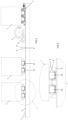
- Fig. 1 thus presents an overview of a storage system for a factory fabricating boards, especially OSB, MDF, or particle boards.
- the board stacks of which there are three, are marked with the reference number 1. There can, of course, be more board stacks but for the sake of clarity not all are presented.
- the board stack at the bottom edge of Fig. 1 is on top of a wagon moving in a crosswise direction, i.e. the main wagon 2.
- the main wagon moves along rails 3. This direction of movement is therefore called the crosswise direction.
- the figure presents a conveyor 4, along which the board stacks come into the storage and exit it.
- the current supply of the main wagon current takes place via the cable 6 of the current supply unit 7.
- the cable 6 winds onto the cable reel 5.
- the main wagon moves away from the current supply unit 7, the cable 6 unwinds from the cable reel 5.
- Fig. 1 presents three longitudinal storage rows 8, each of which is formed from three longitudinal supports 9. There can, of course, be considerably more of these storage rows 8 than three. Additionally, they can be on both sides of the main wagon 2. They are presented here now only on the left-hand side of the main wagon 2 when looking at the figure.
- Fig. 1 also presents a wagon pair comprising two wagons 10 moving side-by-side in a longitudinal direction. They are referred to hereinafter as satellite wagons, and they lift and move board stacks from below.
- a satellite wagon pair that is just going under or coming away from a stack 1.
- the satellite wagon pair 10 is able to lift a stack into the air and to transfer it either from the main wagon 2 onto a storage row 8 or from a storage row 8 onto the main wagon 2.
- a satellite wagon pair 10 is thus disposed in such a way that one satellite wagon is located between the centermost support 9 and one of the outermost supports 9.
- the second satellite wagon is located between the centermost support 9 and the other outermost support 9. Therefore, there are always two satellite wagons side by side and they are called a satellite wagon pair 10.
- Fig. 1 also presents a second pair of satellite wagons, which can be seen slightly under the stack 1 on the left-hand side.
- the main wagon 2 can therefore be arranged to serve more than one satellite wagon pair 10.
- This second satellite wagon pair is not necessarily needed but, particularly in very large storages, it adds capacity.
- a satellite wagon pair 10' can also be seen, which can be a back-up.
- one satellite wagon 10' or both satellite wagons 10' are taken into use from it if a defect occurs in the regular satellite wagons 10 or they otherwise need servicing.
- commissioning of the replacement satellite wagon 10' is easy without requiring installation work or connection work.
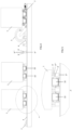
- Fig. 2 presents a storage system as viewed in the direction of the storage rows 8.
- the figure shows how the board stacks 1 are on top of the supports 9 (marked here 9', 9").
- each board stack 1 is supported by three supports 9.
- the satellite wagons 10 are visible between the supports 9.
- more than one satellite wagon pairs are presented, but as presented earlier there might be one or more pairs of them.
- On the right-hand edge of Fig. 2 is the main wagon 2, of which the cable 6 and cable reel 5 are visible.
- a board stack 1 is also on top of the main wagon.
- Fig. 3 shows in more detail one possible structure of a support according to the invention.
- the glued laminated beams of which in this embodiment there are two side by side on each support, are presented with the reference number 9'.
- between the glued laminated beams 9' are e.g. steel parts, such as steel plates, which are supported on the support structure 9'' (or leg) of the support.
- the glued laminated beams 9' are fastened into position from their opposite sides by means of steel plates in a manner described later in this application.
- the support structure 9" of a support is preferably of concrete material or ferroconcrete material.
- the glued laminated beams 9' are fastened into position in such a way that their height when fastened into position is typically greater than their width.
- Commercially available glued laminated beams can be used in the invention and the dimensions can be individually selected according to need.
- Figs. 4 and 5 present an otherwise similar storage system to that in Figs. 2 and 3 , but the structure of the supports is different. Only the structure of the supports, therefore, is described with respect to these drawings.
- the support structure 9'' is again preferably of concrete or ferroconcrete, in which case the part 9′′′ extending between the glued laminated beams 9' is the same structure as the support structure 9".
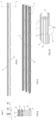
- Fig. 6 presents a side view of the outermost support 9', 9'' of a storage row.
- Fig. 7 presents a C-C section of Fig. 6 while Fig. 8 presents a magnified detail A of Fig. 7 .
- This figure also shows the structure of a glued laminated beam as well as one possible way of fastening it.
- the glued laminated beams 9' are thus placed against the ferroconcrete part 9''' and fastened with bolts 11 extending through the whole structure.
- the structure of a glued laminated beam, wherein the top and bottom layers are of stronger wood than the middle layers, can also be seen from this cross-sectional drawing. They are also of slightly thinner wood than the wood of the middle layers.
- This structure is seen more precisely in Fig. 10 , which presents a magnification of the detail B of Fig. 9 .
- the glued laminated beam 9' comprises eight layers, one on top of the other, the layers being glued to each other, the topmost two and bottommost two layers of which are of stronger wood than the four middle layers. They are also slightly thinner layers. This is, of course, only one possible implementation method, but it is advantageous to use a glued laminated beam having top and bottom layers of stronger wood, because these layers are subjected to greater stresses.
- the middle layers can be of less expensive wood of lower strength.
- Fig. 9 presents one storage row comprising three elongated supports.
- the support structures 9" are arranged at suitable intervals under the glued laminated beams.
- Each satellite wagon has two rails 12 between the longitudinal supports.
- the horizontal load-bearing part of a support can also be formed from three parallel glued laminated beams.
- the centermost glued laminated beam of the three parallel glued laminated beams can be shallower in the height of its cross-section than the glued laminated beams at the edges.
Landscapes
- Engineering & Computer Science (AREA)
- Mechanical Engineering (AREA)
- Warehouses Or Storage Devices (AREA)
Claims (9)
- Système de stockage pour stocker des piles de panneaux (1) dans des rangées de stockage (8), à utiliser dans des usines de fabrication de panneaux, notamment des panneaux OSB, MDF ou de particules, dans lequel chaque rangée de stockage comprend trois supports (9) allongés parallèles, qui sont supportés sur des structures de support (9") agencées à une distance les unes des autres, et entre lesquels supports (9) se trouvent des espaces pour des wagons satellites (10) transportant des piles de panneaux, caractérisé en ce que la partie porteuse horizontale d'un support (9) est formée d'une ou de plusieurs poutres lamellées collées (9').
- Système de stockage selon la revendication 1, caractérisé en ce que la partie porteuse horizontale d'un support (9) est formée de deux poutres lamellées collées (9') parallèles.
- Système de stockage selon la revendication 2, caractérisé en ce que les poutres lamellées collées (9') sont situées à une distance l'une de l'autre.
- Système de stockage selon la revendication 3, caractérisé en ce qu'entre les poutres lamellées collées (9') se trouvent des parties en acier sur lesquelles les poutres lamellées collées (9') sont supportées à partir de leurs surfaces latérales opposées et auxquelles les poutres lamellées collées sont fixées.
- Système de stockage selon la revendication 3, caractérisé en ce qu'entre les poutres lamellées collées (9') se trouvent des parties en béton armé (9‴) sur lesquelles les poutres lamellées collées (9') sont supportées à partir de leurs surfaces latérales opposées et auxquelles les poutres lamellées collées sont fixées.
- Système de stockage selon la revendication 1, caractérisé en ce que la partie porteuse horizontale d'un support est formée de trois poutres lamellées collées (9') parallèles.
- Système de stockage selon la revendication 6, caractérisé en ce que la poutre lamellée collée la plus centrale des trois poutres lamellées collées (9') parallèles est moins profonde dans la hauteur de sa coupe que les poutres lamellées collées au niveau des bords.
- Système de stockage selon l'une quelconque des revendications 1 à 7, caractérisé en ce que les poutres lamellées collées (9') présentent sur la surface haute et la surface basse une ou plusieurs parties de la poutre, les parties ayant une résistance qui est supérieure aux couches intermédiaires.
- Système de stockage selon la revendication 8, caractérisé en ce que les deux couches les plus hautes et les deux couches les plus basses d'une poutre lamellée collée (9') sont en bois, la résistance du bois étant supérieure à celle du bois des couches intermédiaires.
Applications Claiming Priority (2)
| Application Number | Priority Date | Filing Date | Title |
|---|---|---|---|
| FI20205588A FI20205588A1 (fi) | 2020-06-05 | 2020-06-05 | Lastu-, osb- ja mdf-levytehtaissa käytettävä varastojärjestelmä levypinojen varastoimiseksi varastoriveille |
| PCT/EP2021/064470 WO2021244995A1 (fr) | 2020-06-05 | 2021-05-29 | Système de stockage pour stocker des piles de panneaux en rangées de stockage, destiné à être utilisé dans des usines de fabrication de panneaux |
Publications (2)
| Publication Number | Publication Date |
|---|---|
| EP4161850A1 EP4161850A1 (fr) | 2023-04-12 |
| EP4161850B1 true EP4161850B1 (fr) | 2023-10-18 |
Family
ID=76532162
Family Applications (1)
| Application Number | Title | Priority Date | Filing Date |
|---|---|---|---|
| EP21733722.9A Active EP4161850B1 (fr) | 2020-06-05 | 2021-05-29 | Système de stockage pour stocker des piles de panneaux en rangées de stockage, destiné à être utilisé dans des usines de fabrication de panneaux |
Country Status (4)
| Country | Link |
|---|---|
| EP (1) | EP4161850B1 (fr) |
| CN (1) | CN115697862A (fr) |
| FI (1) | FI20205588A1 (fr) |
| WO (1) | WO2021244995A1 (fr) |
Family Cites Families (3)
| Publication number | Priority date | Publication date | Assignee | Title |
|---|---|---|---|---|
| DE9301545U1 (fr) * | 1993-02-04 | 1993-04-22 | Witron Logistik + Informatik Gmbh, 8481 Parkstein, De | |
| CA2233505A1 (fr) * | 1996-07-30 | 1998-02-05 | Westfalia Technologies, Inc. | Systeme de stockage et de recherche automatise pour produits laitiers sans palettes |
| NO324400B1 (no) * | 2002-12-18 | 2007-10-01 | Arne Engebretsen | Konstruksjonselement |
-
2020
- 2020-06-05 FI FI20205588A patent/FI20205588A1/fi unknown
-
2021
- 2021-05-29 EP EP21733722.9A patent/EP4161850B1/fr active Active
- 2021-05-29 WO PCT/EP2021/064470 patent/WO2021244995A1/fr active Application Filing
- 2021-05-29 CN CN202180040201.2A patent/CN115697862A/zh active Pending
Also Published As
| Publication number | Publication date |
|---|---|
| WO2021244995A1 (fr) | 2021-12-09 |
| EP4161850A1 (fr) | 2023-04-12 |
| CN115697862A (zh) | 2023-02-03 |
| FI20205588A1 (fi) | 2021-12-06 |
Similar Documents
| Publication | Publication Date | Title |
|---|---|---|
| KR100843308B1 (ko) | 화물 자동화창고 | |
| US5388955A (en) | High-shelf system store for the storage and the removal from the store of roll-shaped material, more particularly paper rolls, having tracks arranged in pairs for storing paper rolls thereupon | |
| EP4157752A2 (fr) | Système de stockage pour usine de fabrication de panneaux | |
| EP4157753A2 (fr) | Système de stockage destiné à être utilisé dans des usines de fabrication de panneaux, en particulier des panneaux osb, mdf ou de particules | |
| US8397644B2 (en) | Storage and retrieval machine | |
| KR20150034278A (ko) | 오버헤드 크레인 및 적어도 두 개의 오버헤드 크레인의 어셈블리 | |
| US11286112B2 (en) | Warehouse, in particular shuttle warehouse | |
| US20220234827A1 (en) | Storage system | |
| CA2705038A1 (fr) | Palette navette pour systeme de stockage | |
| KR101027232B1 (ko) | 콘테이너 운반선의 화물창에 설치되는 횡격벽 구조 | |
| EP4161850B1 (fr) | Système de stockage pour stocker des piles de panneaux en rangées de stockage, destiné à être utilisé dans des usines de fabrication de panneaux | |
| WO2021240009A1 (fr) | Système de stockage pour stocker des piles de panneaux, destiné à être utilisé dans des usines de fabrication de panneaux | |
| KR101977904B1 (ko) | 이송로봇의 레일가이드 지지장치 | |
| EP4133145A1 (fr) | Station d'assemblage | |
| CN113401498A (zh) | 一种分离式板类构件立体存放转运架 | |
| FI130412B (en) | Lifting system | |
| CN219097294U (zh) | 托盘组件 | |
| JP5662016B2 (ja) | 棒鋼横移し装置 | |
| EP3110724B1 (fr) | Entrepôt | |
| US20080295727A1 (en) | Railcar Support Beam System and Method | |
| CN218116113U (zh) | 一种工字型钢混组合梁用抗震限位装置及限位结构 | |
| CN218023492U (zh) | 货架及储物系统 | |
| CN214453418U (zh) | 一种可调节楼板运输架 | |
| US20170349412A1 (en) | Main girder of crane | |
| CN115258089A (zh) | 甲板片体运输方法 |
Legal Events
| Date | Code | Title | Description |
|---|---|---|---|
| STAA | Information on the status of an ep patent application or granted ep patent |
Free format text: STATUS: UNKNOWN |
|
| STAA | Information on the status of an ep patent application or granted ep patent |
Free format text: STATUS: THE INTERNATIONAL PUBLICATION HAS BEEN MADE |
|
| PUAI | Public reference made under article 153(3) epc to a published international application that has entered the european phase |
Free format text: ORIGINAL CODE: 0009012 |
|
| STAA | Information on the status of an ep patent application or granted ep patent |
Free format text: STATUS: REQUEST FOR EXAMINATION WAS MADE |
|
| 17P | Request for examination filed |
Effective date: 20230102 |
|
| AK | Designated contracting states |
Kind code of ref document: A1 Designated state(s): AL AT BE BG CH CY CZ DE DK EE ES FI FR GB GR HR HU IE IS IT LI LT LU LV MC MK MT NL NO PL PT RO RS SE SI SK SM TR |
|
| GRAP | Despatch of communication of intention to grant a patent |
Free format text: ORIGINAL CODE: EPIDOSNIGR1 |
|
| STAA | Information on the status of an ep patent application or granted ep patent |
Free format text: STATUS: GRANT OF PATENT IS INTENDED |
|
| INTG | Intention to grant announced |
Effective date: 20230705 |
|
| GRAS | Grant fee paid |
Free format text: ORIGINAL CODE: EPIDOSNIGR3 |
|
| DAV | Request for validation of the european patent (deleted) | ||
| DAX | Request for extension of the european patent (deleted) | ||
| P01 | Opt-out of the competence of the unified patent court (upc) registered |
Effective date: 20230808 |
|
| GRAA | (expected) grant |
Free format text: ORIGINAL CODE: 0009210 |
|
| STAA | Information on the status of an ep patent application or granted ep patent |
Free format text: STATUS: THE PATENT HAS BEEN GRANTED |
|
| AK | Designated contracting states |
Kind code of ref document: B1 Designated state(s): AL AT BE BG CH CY CZ DE DK EE ES FI FR GB GR HR HU IE IS IT LI LT LU LV MC MK MT NL NO PL PT RO RS SE SI SK SM TR |
|
| REG | Reference to a national code |
Ref country code: GB Ref legal event code: FG4D |
|
| REG | Reference to a national code |
Ref country code: CH Ref legal event code: EP |
|
| REG | Reference to a national code |
Ref country code: DE Ref legal event code: R096 Ref document number: 602021006047 Country of ref document: DE |
|
| REG | Reference to a national code |
Ref country code: IE Ref legal event code: FG4D |
|
| REG | Reference to a national code |
Ref country code: SE Ref legal event code: TRGR |
|
| REG | Reference to a national code |
Ref country code: LT Ref legal event code: MG9D |
|
| REG | Reference to a national code |
Ref country code: NL Ref legal event code: MP Effective date: 20231018 |
|
| PG25 | Lapsed in a contracting state [announced via postgrant information from national office to epo] |
Ref country code: NL Free format text: LAPSE BECAUSE OF FAILURE TO SUBMIT A TRANSLATION OF THE DESCRIPTION OR TO PAY THE FEE WITHIN THE PRESCRIBED TIME-LIMIT Effective date: 20231018 |
|
| PG25 | Lapsed in a contracting state [announced via postgrant information from national office to epo] |
Ref country code: GR Free format text: LAPSE BECAUSE OF FAILURE TO SUBMIT A TRANSLATION OF THE DESCRIPTION OR TO PAY THE FEE WITHIN THE PRESCRIBED TIME-LIMIT Effective date: 20240119 |
|
| PG25 | Lapsed in a contracting state [announced via postgrant information from national office to epo] |
Ref country code: IS Free format text: LAPSE BECAUSE OF FAILURE TO SUBMIT A TRANSLATION OF THE DESCRIPTION OR TO PAY THE FEE WITHIN THE PRESCRIBED TIME-LIMIT Effective date: 20240218 |
|
| PG25 | Lapsed in a contracting state [announced via postgrant information from national office to epo] |
Ref country code: LT Free format text: LAPSE BECAUSE OF FAILURE TO SUBMIT A TRANSLATION OF THE DESCRIPTION OR TO PAY THE FEE WITHIN THE PRESCRIBED TIME-LIMIT Effective date: 20231018 |
|
| PG25 | Lapsed in a contracting state [announced via postgrant information from national office to epo] |
Ref country code: ES Free format text: LAPSE BECAUSE OF FAILURE TO SUBMIT A TRANSLATION OF THE DESCRIPTION OR TO PAY THE FEE WITHIN THE PRESCRIBED TIME-LIMIT Effective date: 20231018 |
|
| PG25 | Lapsed in a contracting state [announced via postgrant information from national office to epo] |
Ref country code: LT Free format text: LAPSE BECAUSE OF FAILURE TO SUBMIT A TRANSLATION OF THE DESCRIPTION OR TO PAY THE FEE WITHIN THE PRESCRIBED TIME-LIMIT Effective date: 20231018 Ref country code: IS Free format text: LAPSE BECAUSE OF FAILURE TO SUBMIT A TRANSLATION OF THE DESCRIPTION OR TO PAY THE FEE WITHIN THE PRESCRIBED TIME-LIMIT Effective date: 20240218 Ref country code: GR Free format text: LAPSE BECAUSE OF FAILURE TO SUBMIT A TRANSLATION OF THE DESCRIPTION OR TO PAY THE FEE WITHIN THE PRESCRIBED TIME-LIMIT Effective date: 20240119 Ref country code: ES Free format text: LAPSE BECAUSE OF FAILURE TO SUBMIT A TRANSLATION OF THE DESCRIPTION OR TO PAY THE FEE WITHIN THE PRESCRIBED TIME-LIMIT Effective date: 20231018 Ref country code: BG Free format text: LAPSE BECAUSE OF FAILURE TO SUBMIT A TRANSLATION OF THE DESCRIPTION OR TO PAY THE FEE WITHIN THE PRESCRIBED TIME-LIMIT Effective date: 20240118 Ref country code: PT Free format text: LAPSE BECAUSE OF FAILURE TO SUBMIT A TRANSLATION OF THE DESCRIPTION OR TO PAY THE FEE WITHIN THE PRESCRIBED TIME-LIMIT Effective date: 20240219 |