EP4159656A1 - System zur befestigung des freien endes eines spulenfadens - Google Patents
System zur befestigung des freien endes eines spulenfadens Download PDFInfo
- Publication number
- EP4159656A1 EP4159656A1 EP21315193.9A EP21315193A EP4159656A1 EP 4159656 A1 EP4159656 A1 EP 4159656A1 EP 21315193 A EP21315193 A EP 21315193A EP 4159656 A1 EP4159656 A1 EP 4159656A1
- Authority
- EP
- European Patent Office
- Prior art keywords
- wire
- coil
- needle
- turn
- free end
- Prior art date
- Legal status (The legal status is an assumption and is not a legal conclusion. Google has not performed a legal analysis and makes no representation as to the accuracy of the status listed.)
- Granted
Links
Images

Classifications
-
- B—PERFORMING OPERATIONS; TRANSPORTING
- B65—CONVEYING; PACKING; STORING; HANDLING THIN OR FILAMENTARY MATERIAL
- B65H—HANDLING THIN OR FILAMENTARY MATERIAL, e.g. SHEETS, WEBS, CABLES
- B65H65/00—Securing material to cores or formers
- B65H65/005—Securing end of yarn in the wound or completed package
-
- B—PERFORMING OPERATIONS; TRANSPORTING
- B65—CONVEYING; PACKING; STORING; HANDLING THIN OR FILAMENTARY MATERIAL
- B65H—HANDLING THIN OR FILAMENTARY MATERIAL, e.g. SHEETS, WEBS, CABLES
- B65H2701/00—Handled material; Storage means
- B65H2701/30—Handled filamentary material
- B65H2701/31—Textiles threads or artificial strands of filaments
Definitions
- the present invention relates to the field of systems for fixing the free end of a coil wire and more particularly to the field of systems for fixing this free end without adding an additional element to the wire and to the coil.
- the storage of thread or string is conventionally made in the form of balls or in the form of reels.
- the wire is wound around a substantially rectilinear axis over the entire length of this axis, so that the coil thus obtained adopts a substantially cylindrical shape.
- these yarns are wound at the end of the operation in the form of one or more respective coils.
- These spools thus achieve a storage format that allows easy management of the wires until they are used at their final destination.
- Each of the coils of yarn is thus capable of being managed individually within the framework of handling, storage, movement and distribution operations; these operations can be carried out either manually or with the intervention of possibly automated machines.
- a first end of the wire when winding the wire on a reel, a first end of the wire is located at the level of the central axis of the reel and the second end of the wire is positioned on the radial or peripheral surface of the formed coil. If the first end of the wire in the centered position in the coil is perfectly wedged by the various turns of the wound wire which cover it in the coil, such is not the case of the second end of the wire located at the level of the external surface of the coil. Indeed, at the end of winding, this end of the wire is free at the surface of the coil. During the various manipulations and movement of the reel, this end of the wire is then likely to detach from the rest of the reel, dragging at least part of the length of the wire wound on the reel.
- each of the coils is conventionally treated manually by a worker who attaches the free end to the coil by inserting it between two turns of the surface device so as to create a sort of slip knot.
- Such a knot thus avoids detachment of the end of the thread with the rest of the reel, while allowing easy release of this end of the thread when the reel is at its final destination for use. If this solution makes it possible to remove the problem of the management of the free ends of the wires wound on reels, it does however require human intervention with manual management on each of the reels processed. This solution therefore achieves a clear brake in a production line on an industrial scale.
- the object of the present invention is to overcome these drawbacks by proposing a system making it possible to manage the free ends of coil wire by limiting, or even eliminating, any human intervention, while making it possible to discard the intervention of an additional element added to the coil and its wire for fixing the free end of the wire to the coil.
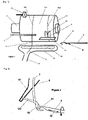
- the attachment system of the invention is configured to allow automation of the attachment of the free end 2 of the wire 1 of a coil 11 to one of the turns 122 of the wire 1 wound on the coil 11 and placed at the level of the peripheral surface 111 of the coil 11.
- This mechanized fixing of the free end 2 of the wire 1 of a coil 11 results in the production of a loop 91 at the level of a portion of the length of the free end 2 of wire 1 of coil 11, then by inserting this loop 91 at the level of a turn 122 of coil 11, so that this loop 91 is pinched by the portion of wire 1 of this turn 122 of the coil 11.
- the loop 91 of the free end 2 of the wire 1 is thus attached to the turn 122 of the coil 11.
- the wire portion 1 of the free end 2 inserted and pinched by the turn 122 of the coil 11 being in the form of a loop 91, this portion of wire 1 attached to the coil 11 is then easily detachable to be recovered when using the coil 11 at its final destination, by simply traction on the free end 2 of the wire 1 outside the loop 91 inserted in a turn 122 of the coil 11.
- the support means 3 has a preferentially axial arrangement, able to be inserted in the axis of a reel 11 of wire 1 to be treated.
- the central axes of the coils 11 are made in the form of a hollow cylindrical element and through which a support means 3 of the coil 11 is able to be inserted.
- the support means 3 has the shape of a concave arrangement of shape substantially complementary to at least a part of the peripheral or radial surface 111 of a coil 11 whose end 2 of the wire 1 is to manage.
- the support means 3 thus forms a housing for receiving the coil 11.
- the support means 3 is likely to be associated with a mechanism for orienting or moving the position of the coil 11 within the framework of its treatment by the attachment system of the invention. Indeed, the position of the coil 11 when it is received by the attachment system of the invention or when it is extracted from the attachment system of the invention is likely to differ from the position of the coil 11 during one or more operating steps of the fastening system of the invention.
- the support means 3 of the coil 11 is arranged to orient the coil 11 in a substantially horizontal manner. It should be noted that this arrangement is likely to involve a motorized mechanism for orienting the axis of the coil 11, once the latter is associated with the support means 3.
- a horizontal orientation of the coil 11 has the advantage of taking advantage of gravity to detach the free end 2 of the wire 1 from the surface 111 of the coil 11. The free end 2 of the wire 1 is then more easily manipulated by the one or other of the elements of the fastening system of the invention.
- the support means 3 is associated with a rotation drive mechanism 5 of the reel 11
- this rotation drive mechanism 5 has the form of a rotating roller about an axis substantially parallel to the axis of the coil 11. The peripheral surface of the roller is then arranged to press against a part of the peripheral surface 111 of the coil 11 and drive it in rotation by friction.
- the rotation drive mechanism 5 is produced by a motor means which operates an axial rotation of the support means 3 when this support means 3 takes the form of a rectilinear axial structure arranged to be inserted into the central axis of the reel 11 and fixed in rotation with the reel 11.
- the rotation drive mechanism 5 of the reel 11 makes it possible to control the unwinding and the winding of the wire 1 with respect to the coil 11 in particular at its free end 2.
- This rotary drive mechanism 5 also makes it possible to operate a tightening of the wire 1 in the coil 11 at the level of the various turns 122 of the coil 11 in particular by jointly operating, on the one hand, a fixed holding of the end 2 free wire 1 and, on the other hand, a rotation of the coil 11 in the direction of a winding of the wire 1.
- the rotation of the coil 11 in the direction of a winding of the wire 1 will in particular make it possible to operate a traction on this wire 1 at the level of the turns which surround the coil 11.
- the rotation drive mechanism 5 involves a motorization which operates the axial rotation of the support means 3, the traction on the wire 1 is exerted from the end of wire 1 located at the level of the central axis of coil 11.
- the needle 4 comprising a hook 41 at its end is of the type used in the context of a knitting machine.
- the orientation of the needle 4 along an axis substantially parallel to the axis of the coil 11 makes it possible to operate an insertion of the needle 4 between the free end 2 of the yarn 1 and the rest of the surface 111 of the coil 11.
- This insertion can be achieved in particular by positioning the needle 4 facing the peripheral surface 111 of the coil 11 then, when the free end 2 of the wire 1 is moved away from the rest of the surface 111 of the coil 11, by moving the needle 4 around the coil 11 in a direction identical to that of the winding of the yarn 1 around the coil 11.
- the needle 4 is thus brought into contact with the yarn 1 at the level of a portion of its free end 2 then to be moved around the coil 11, between the wire 1 and the surface 111 of the coil 11.
- the hook 41 carried by the end of the needle 4 is configured to hook a portion of the thread 1 resting against the surface of the needle 4 when the needle operates an axial translation away from the coil 11.
- the hook 41 is also configured to hook a portion of the thread 1 bearing against the surface of the needle 4 opposite the surface of the needle 4 facing the surface 111 of the coil 11.
- the hook 41 is also configured to allow the portion of the thread 1 positioned inside the hook 41 to be disengaged from the hook 41 in the direction of the part of the needle 4 located on the side opposite the end of the needle 4 which carries the hook 41.
- the hook 41 has a shape configured so that, on the one hand, during a translation of the needle 4 in traction, a portion of yarn 1 positioned inside the hook 41 remains attached to the needle 4 in motion and that, on the other hand, during a translation of the needle 4 in the opposite direction, a portion of thread 1 positioned inside the hook 41 is capable of sliding from the inside of the hook 41 towards the surface of the needle positioned on the opposite side to the end of the needle 4 which carries the hook 41.
- the hook 41 carried by the end of the needle 4 is arranged with an orifice positioned at the level of the lateral surface of the needle 4.
- This orifice has a first edge arranged on the side of the end of the needle 4 and a second edge arranged on the opposite side at the level of the body of the needle 4
- the first edge of the orifice is made by the junction between the concavity of the inside of the hook 41 and the convexity of the end of the needle 4.
- the second edge of the orifice is made by the junction between the inside the hook 41 and the side surface of the body of the needle 4.
- this junction is arranged to present a surface with a relief or limited asperities, or even non-existent. This junction is also likely to have a surface continuity between, on the one hand, the inside of the hook 41 and, on the other hand, the surface of the body of the needle 4.
- the hook 41 carried by the end of the needle 4 is associated with a mechanism 42 for opening/closing the hook 41.
- This mechanism 42 allows a thread to slide against the surface of the needle 4 at the level of the hook 41 without this yarn being hooked by the hook 41 of the needle 4.
- the hook 41 has the shape a closed loop positioned at the end of the needle 4.
- the needle 4 has surface continuity at the level of the portion of the needle 4 which carries the hook 41 so as to facilitate sliding of a thread against the surface of the needle 4.
- the opening/closing mechanism 42 is in the open position, the hook 41 is released and is capable of hooking a thread sliding against the surface of the needle 4.
- this mechanism 42 for opening/closing the hook 41 this mechanism is associated with an actuation motor possibly in combination with an interface for controlling the open/closed position of the hook 41.
- the mechanism 42 for opening/closing the hook 41 of the needle 4 is produced by a valve 42 mounted to pivot around a substantially perpendicular axis. to the axis of the needle 4.
- the pivot axis of the valve 42 is positioned at the level of the side of the orifice of the hook 41 opposite to the end of the needle 4.
- the displacement of the valve 42 takes the form of a pivot radius external to the hook 41.
- this valve 42 is mounted loose with respect to the needle 4 and comprises, at the level of one of its surfaces located level with the surface of the needle 4, a relief with respect to the surface of the needle 4, this relief being capable of interacting with a yarn moving against the surface of the needle 4.
- the movement of a thread 1 against the surface of the needle 4 is hooked by a relief of the valve 42 and causes the pivoting of this valve 42 and therefore the opening or closing of the hook 41 of the needle 4.
- the relative movement of a portion of wire 1 positioned inside the hook 41 with respect to the needle 4 in translation is capable of causing the opening of the valve 42 by the simple force exerted by the portion of yarn 1 against the inner surface of valve 42. This situation is particularly likely to occur when, for example, a portion of yarn 1 has a relaxed tension inside hook 41 and needle 4 is translated axially in a direction opposite to a pull of wire 1.
- the mechanism 42 for opening/closing the hook 41 of the needle 4 is produced by a rod sliding along the axis of the needle 4 to abut against the junction between the concavity of the inside of the hook 41 and the convexity of the end of the needle 4.
- Such a construction of the mechanism 42 of opening/closing of the hook 41 is similar to that of a snap hook.
- the sliding rod is arranged to present, at its outer surface, an optimized surface continuity with the outer surface of the hook 41 and the surface of the needle 4, so that a thread is in able to slide smoothly against the surface of the sliding rod as this yarn moves at hook 41 along the length of needle 4.
- the mechanism 6 for retaining in position a turn 122 of the wire 1 of the coil 11 is an arrangement making it possible to prevent movement along the surface 111 of the coil 11 of a portion of wire 1 separated from the peripheral surface 111 of the coil 11, in particular when this portion of wire 1 is not under tension.
- the retaining mechanism 6 comprises at least one substantially flattened structure arranged to be positioned between, on the one hand, the axis of the needle 4 positioned at a distance from the coil 11 and, on the other hand, on the other hand, the surface 111 of the coil 11.
- This retaining mechanism 6 is preferably associated with a displacement means to allow its positioning between, on the one hand, the needle 4 and, on the other hand, the surface 111 of the spool 11, once the needle 4 has hooked a turn 122 of the thread 1 of the spool 11.
- the structure of the retaining mechanism 6 has a slot 61 open at one of its edges. This slot 61 has a sufficient width to be crossed by a portion of the wire 1 of the coil 11.
- the slot 61 has a shape corresponding substantially to the letter "V" at least at the level of the opening 62 of the slot 61 at the level of the edge of the structure of the retaining mechanism 6, so that this opening 62 of the slot 61 has a width greater than the width of the rest of the slot 61.
- this retaining mechanism 6 is positioned relative to the coil 11, so that the plane of the turn 122 of the coil 11, one of which portion of the wire 1 is intended to be retained in position or placed through the slot 61 and the "V" shaped arrangement of the structure of the retaining mechanism 6.
- the plane of the turn 122 of the coil 11 of which a portion of the wire is intended to be retained corresponds substantially to a plane perpendicular to the axis of the coil 11.
- the system comprises a mechanism for positioning the needle 4 between, on the one hand, a portion of the turn 122 of the wire 1 of the coil 11 which precedes the turn 121 carrying the free end 2 of the wire 1 and, on the other hand, the rest of the coil 11 of wire 1.
- This positioning mechanism is configured to separate the free end 2 of the thread 1 relative to the coil 11 so as to allow the insertion of a part of the needle 4 between the free end 2 of the thread 1 and the coil 11.
- This movement of the needle 4 around the axis of coil 11 is capable of being effected by a pivoting of needle 4 around the axis of coil 11 or by a succession of different translations around the axis of coil 11 .
- the system comprises a mechanism 7 for positioning at least a portion of the turn 121 which carries the free end 2 of wire 1 of the coil 11 at the level of the axis of translation of the needle 4.
- This positioning mechanism 7 of a portion of the turn 121 which carries the free end 2 of the wire 1 is configured to operate a position adjustment of the free end 2 of wire 1 relative to surface 111 of coil 11.
- This mechanism 7 for adjusting the position of a portion of turn 121 which carries free end 2 of wire 1 of coil 11, c that is to say the portion of the wire 1 located between, on the one hand, the free end 2 and, on the other hand, the surface 111 of the coil 11, is also capable of being integrated into the mechanism of positioning of the needle 4 between, on the one hand, a portion of the turn 122 of the thread 1 of the coil 11 which precedes the turn 121 carrying the free end 2 of the thread 1 and, on the other hand, the rest of the coil 11 of wire 1.
- This positioning mechanism 7 of at least a portion of the turn 121 which carries the free end 2 of the wire 1 is thus capable of producing a separation of the free end 2 of the wire 1 with respect to to the surface 111 of the coil 11.
- this positioning mechanism 7 is produced by an element whose structure comprises an axial portion oriented substantially parallel to the axis of the coil 11 of the wire 1.
- This element is configured to be in contact with a portion of the free end 2 of the wire 1 while being movable in a plane perpendicular to the axis of the coil 11, so that the turn 121 which carries the free end 2 of the wire 1, that is to say the portion of the wire 1 located between, on the one hand, the free end 2 and, on the other hand, the surface 111 of the coil 11 , is moved without the coil 11 not supporting any movement.
- this portion of the thread 1 located between the free end 2 and the surface 111 of the coil 11 makes it possible to operate an adjustment of its position relative to the axis of the needle 4. Also, the displacement of this portion of wire 1 allows, on the one hand, its spacing with respect to the surface 111 of the coil 11 and, on the other hand, an adjustment of the position of this portion of wire 1 so that it is aligned on the axial translation axis of the needle 4.
- This alignment thus allows the needle 4 in translation to come into contact with the portion of the wire 1 located between, on the one hand, the free end 2 and, on the other hand, the surface 111 of the coil 11, that is to say the portion of the turn 121 carrying the free end 2 of the wire 1, to hook this portion of the turn 121 by its hook 41 and pull it by needle translation 4.
- the system comprises a mechanism 8 for positioning the free end 2 of the wire 1 of the coil 11 offset with respect to turn 122 of wire 1 of coil 11 which precedes turn 121 carrying free end 2 of wire 1.
- the offset produced by this positioning mechanism 8 is effected along the length of the surface 111 of the coil 11 along the axis of the coil 11. This offset is produced by a displacement of the free end 2 of the wire 1 of the coil 11 according to a translation along an axis substantially parallel to the axis of the coil 11.
- this offset of the free end 2 of the wire 1 is carried out according to a spacing of the free end 2 of the wire 1 with respect to the position of the end of the needle 4 along the surface 111 of the coil 11.
- This offset thus makes it possible to prevent a portion of the wire 1 of the turn 121 carrying the free end 2 of the wire 1 from being superimposed on the turn 122 of the wire 1 of the coil 11 which precedes the turn 121 carrying the free end 2 of the wire 1.
- the mechanism 8 for positioning the free end 2 of the wire 1 of the coil 11 in an offset manner allows the needle 4 to be inserted only between, on the one hand, the surface 111 of the coil 11 and, on the other hand, the turn 122 of the wire 1 which precedes the turn 121 carrying the free end 2 of the wire 1.
- the positioning mechanism 8 of the free end 2 of the wire 1 of the coil 11 is capable of involving a suction means 81 associated with a nozzle 82 whose orifice is substantially elongated and oriented along a substantially horizontal axis and/or parallel to the axis of the coil 11
- the orifice of the nozzle 82 is positioned in a plane, on the one hand, substantially vertical and, on the other hand, disposed in a substantially tangential manner to the surface 111 of the coil 11.
- a construction of the positioning mechanism 8 of the free end 2 of the wire 1 according to this example allows the mechanism to operate a recovery of the free end 2 of the wire 1 which hangs on one side of the coil 11, whatever its position on along the surface 111 of the coil 11.
- the suction means 81 positioned at one end of the nozzle 82 so as to operate a movement of the free end 2 of the wire 1 towards this suction means 81.
- the positioning mechanism 8 of the free end 2 of the wire 1 of the coil 11 is capable of involving an interface for pinching the free end 2 of the wire 1, for example in the form of a pair of counter-rotating rollers arranged along a substantially horizontal axis and/or parallel to the axis of the coil 11, the junction zone of the two rollers being positioned in a plane, on the one hand, substantially vertical and, on the other hand, arranged in a way substantially tangential to the surface 111 of the coil 11.
- This pinching interface is also associated with a means of translation of this pinching interface so as to allow the movement of the free end 2 of the wire 1 of the coil 11 pinched according to a distance from the position of the end of the needle 4 along the surface 111 of the coil 11.
- the system comprises a mechanism for tensioning the free end 2 of the wire 1 of the coil 11.
- This tensioning mechanism is configured to manage the tension or the loosening of the wire 1 with respect in particular to the coil 2, in particular at the level of a portion of the wire 1 corresponding to its free end 2 and to the first turns of the wire 1 from this free end 2 around the coil 11.
- This tensioning mechanism is also capable of being carried out by at least a part of the mechanism 8 for positioning the free end 2 of the wire 1 of the coil 11 detailed above, namely, for example, a suction means 81 or a pair of counter-rotating rollers.
- the support means 3 of the coil 11 is mounted on a structure independent of the other constituent elements of the system. attachment of the invention.
- a construction variant makes it possible to operate an assembly of the various elements which make up the fastening system of the invention at the level of a coil 11 already positioned on an existing support means 3.
- the system of the invention is thus capable of being assembled several times successively level of different coils carried by respective support means 3.
- the structure or structures independent of the support means 3 of the coil 11 which carry one or more of the elements of the system of the invention thus makes it possible to take advantage of the support means 3 of the coil 11 already used at the level of one or more other points.
- the rotation drive mechanism 5 of the coil 11 is capable of being carried by the same structure as that which carries the support means 3 of the coil 11 or, alternatively, by another independent structure.
- the step of axial pivoting of the needle 4 is carried out by an axial rotation of the needle 4 by at least one complete turn for the production of a loop 92 from the portion of wire 1 hooked to needle 4.
- the wire portion 1 of turn 122 of coil 11 hooked to needle 4 is kept in tension at the inside hook 41 of needle 4.
- the method comprises a step of retaining in position the portion of the turn 122 forming the loop 92 of wire 1 made so that the needle 4 translates easily through the loop 92 of wire 1.
- This step of retaining the wire portion 1 of the turn 122 of the spool 11 which makes the loop 92 of yarn 1 around the axis of the needle 4 is carried out thanks to a retaining mechanism 6 in position arranged to block any movement, over the length of the surface 111 of the spool 11 , of the wire portion 1 of the turn 122 which forms the loop 92.
- the tension exerted on the wire portion 1 of the turn 122 which forms the loop 92 is released, so as to facilitate the disengagement of the loop 92 of thread 1 from the hook 41 of the needle 4 and the axial translation of the needle 4 through this loop 91 of thread 1.
- the step of pulling a portion of the turn 121 carrying the free end 2 of the wire 1 of the coil 11 through the loop 92 of wire 1 produced by the portion of the turn 122 of the wire 1 of the coil 11 which precedes the turn 121 carrying the free end 2 of the wire 1 is produced over a length sufficient to allow the production of a loop 91 of wire 1 through the loop 92 of wire 1 previously formed.
- this pulling step is stopped before the free end 2 of wire 1 passes through this loop 92 of wire 1 previously formed, so that the portion of wire 1 positioned at the level of the free end 2 of the yarn 1 makes a slip knot through the loop 92 of yarn 1 previously formed.
- the method comprises a step of tightening the loop 92 formed by the turn 122 of the thread of the bobbin which precedes the turn 121 carrying the end free end 2 of the wire 1, around the portion of the turn 121 carrying the free end 2 of the wire 1 positioned through this loop 92.
- the tightening of the loop 92 is capable of being carried out by pulling the wire 1 at the level of each of the wire portions 1 located on either side of the loop 92.
- the step of tightening the loop 92 is carried out by pulling at a portion of the wire 1 positioned upstream of the loop 92 crossed by the portion of the turn 121 carrying the free end 2 of the thread 1 that the hook 41 of the needle 4 holds.
- this step of tightening the loop 92 is effected by pulling at the portion of the wire 1 positioned on the side opposite the free end 2 of the wire 1 with respect to the position of the loop 122.
- the method prior to the step of pulling a portion of the turn 121 carrying the end free end 2 of wire 1 of coil 11 through loop 92 of wire made by the portion of turn 122 of wire 1 of coil 11 which precedes turn 121 carrying free end 2 of wire 1, the method comprises a step of closing the hook 41 of the needle 4 having hooked the turn 121 carrying the free end 2 of the thread 1 of the coil 11.
- the mechanism 42 for opening/closing the hook 41 involves a valve 42 comprising a relief protruding from relative to the surface of the needle 4 when this valve 42 is in the open position of the hook 41 of the needle 4.
- the yarn 1 of the loop 92 through which the needle 4 slides slides against the surface of the needle 4 in the direction of the hook 41.
- the wire 1 of the loop 92 comes into contact with the relief of the flap 42 and interacts with the latter to push the flap 42 and cause it to pivot into the closed position of the hook 41, so that in reaching the hook 41 of the needle 4, the thread 1 of the loop 92 slides against the surface of the valve 42 which closes the orifice of the hook 41.
- the method comprises beforehand a step of shifting the free end 2 of the wire 1 from the coil 11 with respect to the position of the turn 122 of the wire 1 of the coil 11 which precedes the turn 122 carrying the free end 2 of the wire 1.
- the free end 2 of the wire 1 of the coil 11 is moved in translation along an axis substantially parallel to the axis of the coil 11.
- this offset of the free end 2 of the wire 1 is carried out according to a spacing of the end free 2 of the wire 1 with respect to the position of the end of the needle 4 along the surface 111 of the coil 11.
Landscapes
- Engineering & Computer Science (AREA)
- Textile Engineering (AREA)
- Sewing Machines And Sewing (AREA)
- Spinning Or Twisting Of Yarns (AREA)
- Manufacture Of Motors, Generators (AREA)
Priority Applications (3)
| Application Number | Priority Date | Filing Date | Title |
|---|---|---|---|
| EP21315193.9A EP4159656B1 (de) | 2021-09-30 | 2021-09-30 | System zur befestigung des freien endes eines spulenfadens |
| US17/951,458 US12434939B2 (en) | 2021-09-30 | 2022-09-23 | System for attaching the free end of a spool thread |
| CN202211190423.5A CN115893098A (zh) | 2021-09-30 | 2022-09-28 | 用于系紧线轴的线的自由端的系统 |
Applications Claiming Priority (1)
| Application Number | Priority Date | Filing Date | Title |
|---|---|---|---|
| EP21315193.9A EP4159656B1 (de) | 2021-09-30 | 2021-09-30 | System zur befestigung des freien endes eines spulenfadens |
Publications (3)
| Publication Number | Publication Date |
|---|---|
| EP4159656A1 true EP4159656A1 (de) | 2023-04-05 |
| EP4159656B1 EP4159656B1 (de) | 2024-11-13 |
| EP4159656C0 EP4159656C0 (de) | 2024-11-13 |
Family
ID=78528845
Family Applications (1)
| Application Number | Title | Priority Date | Filing Date |
|---|---|---|---|
| EP21315193.9A Active EP4159656B1 (de) | 2021-09-30 | 2021-09-30 | System zur befestigung des freien endes eines spulenfadens |
Country Status (3)
| Country | Link |
|---|---|
| US (1) | US12434939B2 (de) |
| EP (1) | EP4159656B1 (de) |
| CN (1) | CN115893098A (de) |
Families Citing this family (1)
| Publication number | Priority date | Publication date | Assignee | Title |
|---|---|---|---|---|
| US12129576B2 (en) * | 2021-09-16 | 2024-10-29 | Belmont Textile Machinery Company | Automated yarn package handling system and method |
Citations (3)
| Publication number | Priority date | Publication date | Assignee | Title |
|---|---|---|---|---|
| US3323189A (en) * | 1963-12-28 | 1967-06-06 | Asahi Chemical Ind | Methods and apparatus for lacing yarn masses by strings |
| JPH09240924A (ja) * | 1996-03-12 | 1997-09-16 | Murata Mach Ltd | パッケージの糸結び方法及び糸結び装置 |
| US20020060455A1 (en) * | 2000-10-24 | 2002-05-23 | Thomas Jay Dee | Automatic knot-tying machine |
Family Cites Families (3)
| Publication number | Priority date | Publication date | Assignee | Title |
|---|---|---|---|---|
| JPH0729728B2 (ja) * | 1986-10-24 | 1995-04-05 | 村田機械株式会社 | パッケ−ジの糸処理装置 |
| US6964437B2 (en) * | 2001-12-14 | 2005-11-15 | Superba (Societa Anonyme) | Process and device for knotting a yarn on a spool |
| JP5977127B2 (ja) * | 2012-09-12 | 2016-08-24 | 三工機器株式会社 | ステータコイルのレーシング結束方法及びレーシング結束装置 |
-
2021
- 2021-09-30 EP EP21315193.9A patent/EP4159656B1/de active Active
-
2022
- 2022-09-23 US US17/951,458 patent/US12434939B2/en active Active
- 2022-09-28 CN CN202211190423.5A patent/CN115893098A/zh active Pending
Patent Citations (3)
| Publication number | Priority date | Publication date | Assignee | Title |
|---|---|---|---|---|
| US3323189A (en) * | 1963-12-28 | 1967-06-06 | Asahi Chemical Ind | Methods and apparatus for lacing yarn masses by strings |
| JPH09240924A (ja) * | 1996-03-12 | 1997-09-16 | Murata Mach Ltd | パッケージの糸結び方法及び糸結び装置 |
| US20020060455A1 (en) * | 2000-10-24 | 2002-05-23 | Thomas Jay Dee | Automatic knot-tying machine |
Also Published As
| Publication number | Publication date |
|---|---|
| US12434939B2 (en) | 2025-10-07 |
| US20230114121A1 (en) | 2023-04-13 |
| EP4159656B1 (de) | 2024-11-13 |
| CN115893098A (zh) | 2023-04-04 |
| EP4159656C0 (de) | 2024-11-13 |
Similar Documents
| Publication | Publication Date | Title |
|---|---|---|
| EP0554212B1 (de) | Wickelvorrichtung für die Aufhängungsseile eines Stores | |
| EP0340102B1 (de) | Vorrichtung zum Aufwickeln von fadenförmigem Material auf einen Wickeldorn beliebiger Form und dieselbe verwendende Aufwickelmaschine | |
| WO2019073131A1 (fr) | Dispositif de suture d'une prothese valvulaire cardiaque | |
| EP4159656B1 (de) | System zur befestigung des freien endes eines spulenfadens | |
| EP2004534B1 (de) | Verfahren zur herstellung einer wicklung mit getrennten fäden | |
| EP3288878B1 (de) | Maschine zur herstellung von optischen fasern und verfahren zur positionierung der optischen faser in solch einer maschine | |
| FR2878241A1 (fr) | Machine automatique pour la formation d'un noeud a l'aide d'une ficelle en extremite d'une gaine tubulaire en vue de l'obturer par constriction sous l'effet du serrage du noeud | |
| FR2531311A1 (fr) | Appareil de halage et d'arrimage d'une longue ligne a peche comportant plusieurs hamecons | |
| EP0500433B1 (de) | Verfahren und Vorrichtung zum Befestigen des Fadenendes einer Spule | |
| FR2710238A1 (fr) | Moulinet de pêche à dispositif de tension de fil . | |
| EP0266286B1 (de) | Vorrichtung zum Schusseintrag bei schützenlosen Webmaschinen | |
| WO2002030176A1 (fr) | Devidoir suspendu, notamment pour cultures | |
| EP4186836A1 (de) | System zum aufwickeln eines garnendes | |
| FR2537961A1 (fr) | Procede de raccordement de files | |
| EP4469240A1 (de) | Tragbare elektrische bindemaschine zum binden von pflanzen | |
| EP1319623B1 (de) | Verfahren und Vorrichtung zum Knoten eines Fadens an einer Spule | |
| FR2842263A1 (fr) | Agrafes implantables par vissage dans une structure a mailles notamment pour joint de four et procede de fabrication d'un joint de four equipe de telles agrafes | |
| FR2460126A1 (fr) | Distributeur de fil, en particulier pour les sutures chirurgicales | |
| CH290852A (fr) | Machine à bobiner les canettes. | |
| EP2242387B1 (de) | Verfahren und vorrichtung zur anordnung von trägern mit einem achter-ring | |
| FR2651761A1 (fr) | Appareil pour la pose automatique notamment d'un ruban adhesif sur un produit. | |
| CH633832A5 (fr) | Dispositif manuel d'amorcage avec formation d'une reserve de fil sur une machine textile equipee d'un mecanisme de bobinage. | |
| WO2023148664A1 (fr) | Dispositif d'aide à l'enfilage d'une aiguille a chas | |
| FR2859351A1 (fr) | Dispositif pour guider les plantes et methode pour la fabrication d'un tel dispositif | |
| CH287531A (fr) | Procédé de tissage et métier pour la mise en oeuvre de ce procédé. |
Legal Events
| Date | Code | Title | Description |
|---|---|---|---|
| PUAI | Public reference made under article 153(3) epc to a published international application that has entered the european phase |
Free format text: ORIGINAL CODE: 0009012 |
|
| STAA | Information on the status of an ep patent application or granted ep patent |
Free format text: STATUS: THE APPLICATION HAS BEEN PUBLISHED |
|
| STAA | Information on the status of an ep patent application or granted ep patent |
Free format text: STATUS: REQUEST FOR EXAMINATION WAS MADE |
|
| AK | Designated contracting states |
Kind code of ref document: A1 Designated state(s): AL AT BE BG CH CY CZ DE DK EE ES FI FR GB GR HR HU IE IS IT LI LT LU LV MC MK MT NL NO PL PT RO RS SE SI SK SM TR |
|
| 17P | Request for examination filed |
Effective date: 20230327 |
|
| RBV | Designated contracting states (corrected) |
Designated state(s): AL AT BE BG CH CY CZ DE DK EE ES FI FR GB GR HR HU IE IS IT LI LT LU LV MC MK MT NL NO PL PT RO RS SE SI SK SM TR |
|
| GRAP | Despatch of communication of intention to grant a patent |
Free format text: ORIGINAL CODE: EPIDOSNIGR1 |
|
| STAA | Information on the status of an ep patent application or granted ep patent |
Free format text: STATUS: GRANT OF PATENT IS INTENDED |
|
| INTG | Intention to grant announced |
Effective date: 20240613 |
|
| GRAS | Grant fee paid |
Free format text: ORIGINAL CODE: EPIDOSNIGR3 |
|
| GRAA | (expected) grant |
Free format text: ORIGINAL CODE: 0009210 |
|
| STAA | Information on the status of an ep patent application or granted ep patent |
Free format text: STATUS: THE PATENT HAS BEEN GRANTED |
|
| AK | Designated contracting states |
Kind code of ref document: B1 Designated state(s): AL AT BE BG CH CY CZ DE DK EE ES FI FR GB GR HR HU IE IS IT LI LT LU LV MC MK MT NL NO PL PT RO RS SE SI SK SM TR |
|
| REG | Reference to a national code |
Ref country code: GB Ref legal event code: FG4D Free format text: NOT ENGLISH |
|
| REG | Reference to a national code |
Ref country code: CH Ref legal event code: EP |
|
| REG | Reference to a national code |
Ref country code: IE Ref legal event code: FG4D Free format text: LANGUAGE OF EP DOCUMENT: FRENCH |
|
| REG | Reference to a national code |
Ref country code: DE Ref legal event code: R096 Ref document number: 602021021743 Country of ref document: DE |
|
| U01 | Request for unitary effect filed |
Effective date: 20241203 |
|
| U07 | Unitary effect registered |
Designated state(s): AT BE BG DE DK EE FI FR IT LT LU LV MT NL PT RO SE SI Effective date: 20241212 |
|
| PG25 | Lapsed in a contracting state [announced via postgrant information from national office to epo] |
Ref country code: HR Free format text: LAPSE BECAUSE OF FAILURE TO SUBMIT A TRANSLATION OF THE DESCRIPTION OR TO PAY THE FEE WITHIN THE PRESCRIBED TIME-LIMIT Effective date: 20241113 Ref country code: IS Free format text: LAPSE BECAUSE OF FAILURE TO SUBMIT A TRANSLATION OF THE DESCRIPTION OR TO PAY THE FEE WITHIN THE PRESCRIBED TIME-LIMIT Effective date: 20250313 |
|
| PG25 | Lapsed in a contracting state [announced via postgrant information from national office to epo] |
Ref country code: ES Free format text: LAPSE BECAUSE OF FAILURE TO SUBMIT A TRANSLATION OF THE DESCRIPTION OR TO PAY THE FEE WITHIN THE PRESCRIBED TIME-LIMIT Effective date: 20241113 |
|
| PG25 | Lapsed in a contracting state [announced via postgrant information from national office to epo] |
Ref country code: NO Free format text: LAPSE BECAUSE OF FAILURE TO SUBMIT A TRANSLATION OF THE DESCRIPTION OR TO PAY THE FEE WITHIN THE PRESCRIBED TIME-LIMIT Effective date: 20250213 |
|
| PG25 | Lapsed in a contracting state [announced via postgrant information from national office to epo] |
Ref country code: GR Free format text: LAPSE BECAUSE OF FAILURE TO SUBMIT A TRANSLATION OF THE DESCRIPTION OR TO PAY THE FEE WITHIN THE PRESCRIBED TIME-LIMIT Effective date: 20250214 |
|
| PG25 | Lapsed in a contracting state [announced via postgrant information from national office to epo] |
Ref country code: PL Free format text: LAPSE BECAUSE OF FAILURE TO SUBMIT A TRANSLATION OF THE DESCRIPTION OR TO PAY THE FEE WITHIN THE PRESCRIBED TIME-LIMIT Effective date: 20241113 |
|
| PG25 | Lapsed in a contracting state [announced via postgrant information from national office to epo] |
Ref country code: RS Free format text: LAPSE BECAUSE OF FAILURE TO SUBMIT A TRANSLATION OF THE DESCRIPTION OR TO PAY THE FEE WITHIN THE PRESCRIBED TIME-LIMIT Effective date: 20250213 |
|
| PG25 | Lapsed in a contracting state [announced via postgrant information from national office to epo] |
Ref country code: SM Free format text: LAPSE BECAUSE OF FAILURE TO SUBMIT A TRANSLATION OF THE DESCRIPTION OR TO PAY THE FEE WITHIN THE PRESCRIBED TIME-LIMIT Effective date: 20241113 |
|
| PG25 | Lapsed in a contracting state [announced via postgrant information from national office to epo] |
Ref country code: SK Free format text: LAPSE BECAUSE OF FAILURE TO SUBMIT A TRANSLATION OF THE DESCRIPTION OR TO PAY THE FEE WITHIN THE PRESCRIBED TIME-LIMIT Effective date: 20241113 |
|
| PG25 | Lapsed in a contracting state [announced via postgrant information from national office to epo] |
Ref country code: CZ Free format text: LAPSE BECAUSE OF FAILURE TO SUBMIT A TRANSLATION OF THE DESCRIPTION OR TO PAY THE FEE WITHIN THE PRESCRIBED TIME-LIMIT Effective date: 20241113 |
|
| PLBE | No opposition filed within time limit |
Free format text: ORIGINAL CODE: 0009261 |
|
| STAA | Information on the status of an ep patent application or granted ep patent |
Free format text: STATUS: NO OPPOSITION FILED WITHIN TIME LIMIT |
|
| U20 | Renewal fee for the european patent with unitary effect paid |
Year of fee payment: 5 Effective date: 20250826 |
|
| PGFP | Annual fee paid to national office [announced via postgrant information from national office to epo] |
Ref country code: TR Payment date: 20250912 Year of fee payment: 5 |
|
| 26N | No opposition filed |
Effective date: 20250814 |