EP4159656B1 - System zur befestigung des freien endes eines spulenfadens - Google Patents
System zur befestigung des freien endes eines spulenfadens Download PDFInfo
- Publication number
- EP4159656B1 EP4159656B1 EP21315193.9A EP21315193A EP4159656B1 EP 4159656 B1 EP4159656 B1 EP 4159656B1 EP 21315193 A EP21315193 A EP 21315193A EP 4159656 B1 EP4159656 B1 EP 4159656B1
- Authority
- EP
- European Patent Office
- Prior art keywords
- needle
- yarn
- turn
- free end
- bobbin
- Prior art date
- Legal status (The legal status is an assumption and is not a legal conclusion. Google has not performed a legal analysis and makes no representation as to the accuracy of the status listed.)
- Active
Links
Images

Classifications
-
- B—PERFORMING OPERATIONS; TRANSPORTING
- B65—CONVEYING; PACKING; STORING; HANDLING THIN OR FILAMENTARY MATERIAL
- B65H—HANDLING THIN OR FILAMENTARY MATERIAL, e.g. SHEETS, WEBS, CABLES
- B65H65/00—Securing material to cores or formers
- B65H65/005—Securing end of yarn in the wound or completed package
-
- B—PERFORMING OPERATIONS; TRANSPORTING
- B65—CONVEYING; PACKING; STORING; HANDLING THIN OR FILAMENTARY MATERIAL
- B65H—HANDLING THIN OR FILAMENTARY MATERIAL, e.g. SHEETS, WEBS, CABLES
- B65H2701/00—Handled material; Storage means
- B65H2701/30—Handled filamentary material
- B65H2701/31—Textiles threads or artificial strands of filaments
Definitions
- the present invention relates to the field of systems for fixing the free end of a coil wire and more particularly to the field of systems for fixing this free end without adding an additional element to the wire and to the coil.
- the storage of thread or string is conventionally carried out in the form of balls or in the form of spools.
- the thread is wound around a substantially rectilinear axis over the entire length of this axis, so that the spool thus obtained adopts a substantially cylindrical shape.
- these threads are wound at the end of the operation in the form of one or more respective spools.
- These spools thus provide a storage format that allows for easy management of the threads until they are used at their final destination.
- Each of the spools of thread is thus capable of being managed individually in the context of handling, storage, movement and distribution operations; these operations can be carried out either manually or with the intervention of possibly automated machines.
- a first end of the wire is located at the central axis of the spool and the second end of the wire is positioned on the radial or peripheral surface of the formed spool. If the first end of the wire in the centered position in the spool is perfectly wedged by the different turns of the wound wire that cover it in the spool, this is not the case for the second end of the wire located at the outer surface of the spool. Indeed, at the end of winding, this end of the wire is free on the surface of the spool.
- this end of the wire is then likely to become detached from the rest of the spool, taking with it at least part of the length of the wire wound onto the spool.
- Such a situation occurs in particular when the texture of the wire wound onto a spool is smooth and has limited gripping capacity with the surface of the turns that form the outer surface or peripheral of the coil.
- a free end of the wire poses a danger to a production, processing or management site. Indeed, when the length of this end of the wire increases, the risk of it being caught by a machine and causing operating problems increases. The consequences of such a situation can quickly become dramatic.
- each of the coils is traditionally processed manually by a worker who attaches the free end to the coil by inserting it between two turns of the peripheral surface so as to create a sort of slip knot.
- Such a knot thus prevents the end of the wire from becoming detached from the rest of the coil, while allowing easy release of this end of the wire when the coil is at its final destination for use.
- this solution eliminates the problem of managing the free ends of the wires wound on coils, it does require human intervention with manual management on each of the coils processed. This solution therefore creates a clear obstacle in an industrial-scale production line.
- the publication US 2002/060455 proposes a mechanized device for tying the free end of a thread with one of the turns of the spool. This device is based in particular on a sliding hook for catching the end of the thread to allow its management in relation to the thread wound on the spool.
- the present invention aims to overcome these drawbacks by proposing a system for managing the free ends of the coil wire by limiting, or even eliminating, any human intervention, while making it possible to avoid the intervention of an additional element added to the coil and its wire for fixing the free end of the wire to the coil.
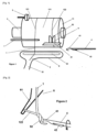
- the attachment system of the invention is configured to allow automation of the attachment of the free end 2 of the wire 1 of a spool 11 to one of the turns 122 of the wire 1 wound on the spool 11 and arranged at the peripheral surface 111 of the spool 11.
- This mechanized attachment of the free end 2 of the wire 1 of a spool 11 results in the creation of a loop 91 at a portion of the length of the free end 2 of the wire 1 of the spool 11, then by the insertion of this loop 91 at a turn 122 of the spool 11, such that this loop 91 is pinched by the portion of the wire 1 of this turn 122 of the spool 11.
- the loop 91 of the free end 2 of the wire 1 is thus attached to the turn 122 of the coil 11.
- the portion of wire 1 of the free end 2 inserted and pinched by the turn 122 of the coil 11 being in the form of a loop 91, this portion of wire 1 attached to the coil 11 is then easily detachable to be recovered when using the coil 11 at its final destination, by simple traction on the free end 2 of the wire 1 outside the loop 91 inserted in a turn 122 of the coil 11.
- the support means 3 has a preferentially axial arrangement, capable of being inserted into the axis of a spool 11 of wire 1 to be processed.
- the central axes of the spools 11 are made in the form of a hollow cylindrical element and through which a support means 3 of the spool 11 is capable of being inserted.
- the support means 3 has the form of a concave arrangement of a shape substantially complementary to at least part of the peripheral or radial surface 111 of a spool 11 whose end 2 of the wire 1 is to be managed.
- the support means 3 thus provides a housing for receiving the spool 11.
- the support means 3 is likely to be associated with a mechanism for orienting or moving the position of the spool 11 in the context of its processing by the attachment system of the invention. Indeed, the position of the coil 11 when it is received by the attachment system of the invention or when it is extracted from the attachment system of the invention is likely to differ from the position of the coil 11 during one or more operating steps of the attachment system of the invention.
- the support means 3 of the spool 11 is arranged to orient the spool 11 in a substantially horizontal manner. It should be noted that this arrangement is capable of involving a motorized mechanism for orienting the axis of the spool 11, once the latter is associated with the support means 3.
- a horizontal orientation of the spool 11 has the advantage of taking advantage of gravity to detach the free end 2 of the wire 1 from the surface 111 of the spool 11. The end 2 free of wire 1 is then more easily manipulated by one or other of the elements of the attachment system of the invention.
- the support means 3 is associated with a rotation drive mechanism 5 of the coil 11.
- this rotation drive mechanism 5 has the shape of a roller rotating about an axis substantially parallel to the axis of the coil 11. The peripheral surface of the roller is then arranged to press against a part of the peripheral surface 111 of the coil 11 and drive it in rotation by friction.
- the rotation drive mechanism 5 is produced by a motor means which operates an axial rotation of the support means 3 when this support means 3 takes the form of a rectilinear axial structure arranged to be inserted into the central axis of the spool 11 and fixed in rotation with the spool 11.
- the rotation drive mechanism 5 of the spool 11 makes it possible to control the unwinding and winding of the wire 1 relative to the spool 11, in particular at its free end 2.
- This rotation drive mechanism 5 also makes it possible to tighten the wire 1 in the spool 11 at the various turns 122 of the spool 11, in particular by jointly operating, on the one hand, a fixed hold of the free end 2 of the wire 1 and, on the other hand, a rotation of the spool 11 in the direction of winding the wire 1.
- the rotation of the spool 11 in the direction of winding the wire 1 will in particular make it possible to exert traction on this wire 1 at the turns surrounding the spool 11.
- the rotation drive mechanism 5 involves a motor that operates the axial rotation of the support means 3, the traction on the wire 1 is exerted from the end of the wire 1 located at the central axis of the spool 11.
- the needle 4 comprising a hook 41 at its end is of the type used in the context of a knitting machine.
- the orientation of the needle 4 along an axis substantially parallel to the axis of the bobbin 11 makes it possible to insert the needle 4 between the free end 2 of the thread 1 and the remainder of the surface 111 of the bobbin 11.
- This insertion is in particular achievable by positioning the needle 4 opposite the peripheral surface 111 of the spool 11 then, when the free end 2 of the wire 1 is separated from the rest of the surface 111 of the spool 11, by moving the needle 4 around the spool 11 in a direction identical to that of the winding of the wire 1 around the spool 11.
- the needle 4 is thus caused to come into contact with the wire 1 at a portion of its free end 2 then to be moved around the spool 11, between the wire 1 and the surface 111 of the spool 11.
- the hook 41 carried by the end of the needle 4 is configured to hook a portion of the wire 1 bearing against the surface of the needle 4 when the needle performs an axial translation away from the spool 11.
- the hook 41 is also configured to hook a portion of the wire 1 bearing against the surface of the needle 4 opposite the surface of the needle 4 in with respect to the surface 111 of the bobbin 11.
- the hook 41 is also configured to allow the portion of the thread 1 positioned inside the hook 41 to be released from the hook 41 towards the part of the needle 4 located on the side opposite the end of the needle 4 which carries the hook 41.
- the hook 41 has a shape configured so that, on the one hand, during a translation of the needle 4 in traction, a portion of thread 1 positioned inside the hook 41 remains attached to the needle 4 in movement and that, on the other hand, during a translation of the needle 4 in the opposite direction, a portion of thread 1 positioned inside the hook 41 is capable of sliding from the inside of the hook 41 towards the surface of the needle positioned on the side opposite the end of the needle 4 which carries the hook 41.
- the hook 41 carried by the end of the needle 4 is arranged with an orifice positioned at the lateral surface of the needle 4.
- This orifice has a first edge arranged on the side of the end of the needle 4 and a second edge arranged on the opposite side at the body of the needle 4.
- the first edge of the orifice is produced by the junction between the concavity of the inside of the hook 41 and the convexity of the end of the needle 4.
- the second edge of the orifice is produced by the junction between the inside of the hook 41 and the lateral surface of the body of the needle 4.
- this junction is arranged to have a surface with a relief or asperities that are restricted, or even non-existent. This junction is also likely to present a surface continuity between, on the one hand, the interior of the hook 41 and, on the other hand, the surface of the body of the needle 4.
- the hook 41 carried by the end of the needle 4 is associated with a mechanism 42 for opening/closing the hook 41.
- This mechanism 42 makes it possible to slide a thread against the surface of the needle 4 at the hook 41 without this thread being caught by the hook 41 of the needle 4.
- the hook 41 has the shape of a closed loop positioned at the end of the needle 4.
- the needle 4 has surface continuity at the portion of the needle 4 which carries the hook 41 so as to facilitate the sliding of a thread against the surface of the needle 4.
- the opening/closing mechanism 42 is in the open position, the hook 41 is released and is able to catch a thread sliding against the surface of the needle 4.
- this mechanism 42 is associated with an actuation motorization possibly in combination with an interface for controlling the open/closed position of the hook 41.
- the mechanism 42 for opening/closing the hook 41 of the needle 4 is produced by a flap 42 pivotally mounted about an axis substantially perpendicular to the axis of the needle 4.
- the pivot axis of the flap 42 is positioned at the side of the orifice of the hook 41 opposite the end of the needle 4.
- the movement of the flap 42 is carried out in the form of a pivot radius external to the hook 41.
- this flap 42 is mounted loosely relative to the needle 4 and comprises, at the level of one of its surfaces located level with the surface of the needle 4, a relief relative to the surface of the needle 4, this relief being capable of interacting with a thread moving against the surface of the needle 4.
- the movement of a thread 1 against the surface of the needle 4 is hooked by a relief of the flap 42 and causes the pivoting of this flap 42 and therefore the opening or closing of the hook 41 of the needle 4.
- the relative movement of a portion of thread 1 positioned inside the hook 41 relative to the needle 4 in translation is likely to cause the opening of the flap 42 by the simple force exerted by the portion of the thread 1 against the inner surface of the flap 42. This situation is particularly likely to occur when, for example, a portion of thread 1 has a tension released at inside the hook 41 and that the needle 4 is translated axially in a direction opposite to a traction of the thread 1.
- the mechanism 42 for opening/closing the hook 41 of the needle 4 is produced by a rod sliding along the axis of the needle 4 to abut against the junction between the concavity of the interior of the hook 41 and the convexity of the end of the needle 4.
- Such a construction of the mechanism 42 for opening/closing the hook 41 is similar to that of a latch carabiner.
- the sliding rod is arranged to have, at its outer surface, an optimized surface continuity with the outer surface of the hook 41 and the surface of the needle 4, so that a wire is able to slide without difficulty against the surface of the sliding rod when this wire moves at the hook 41 over the length of the needle 4.
- the mechanism 6 for retaining in position a turn 122 of the wire 1 of the coil 11 is an arrangement making it possible to prevent the movement along the surface 111 of the coil 11 of a portion of wire 1 spaced from the peripheral surface 111 of the coil 11, in particular when this portion of wire 1 is not under tension.
- the retaining mechanism 6 comprises at least one substantially flattened structure arranged to be positioned between, on the one hand, the axis of the needle 4 positioned at a distance from the bobbin 11 and, on the other hand, the surface 111 of the bobbin 11.
- This retaining mechanism 6 is preferably associated with a displacement means to allow its positioning between, on the one hand, the needle 4 and, on the other hand, the surface 111 of the bobbin 11, once the needle 4 has hooked a turn 122 of the wire 1 of the bobbin 11.
- the structure of the retaining mechanism 6 has a slot 61 open at one of its edges. This slot 61 has a width sufficient to be crossed by a portion of the wire 1 of the coil 11.
- the slot 61 has a shape corresponding substantially to the letter “V” at least at the level of the opening 62 of the slot 61 at the level of the edge of the structure of the retaining mechanism 6, so that this opening 62 of the slot 61 has a width greater than the width of the remainder of the slot 61.
- this retaining mechanism 6 is positioned relative to the spool 11, such that the plane of the turn 122 of the spool 11 of which a portion of the wire 1 is intended to be retained in position is arranged across the slot 61 and the “V”-shaped arrangement of the structure of the retaining mechanism 6.
- the plane of the turn 122 of the spool 11 of which a portion of the wire is intended to be retained corresponds substantially to a plane perpendicular to the axis of the spool 11.
- the system comprises a mechanism for positioning the needle 4 between, on the one hand, a portion of the turn 122 of the wire 1 of the spool 11 which precedes the turn 121 carrying the free end 2 of the wire 1 and, on the other hand, the remainder of the spool 11 of wire 1.
- This positioning mechanism is configured to move the free end 2 of the wire 1 away from the spool 11 so as to allow the insertion of a portion of the needle 4 between the free end 2 of the wire 1 and the spool 11.
- This movement of the needle 4 around the axis of the bobbin 11 is capable of being carried out by a pivoting of the needle 4 around the axis of the coil 11 or by a succession of different translations around the axis of coil 11.
- the system comprises a mechanism 7 for positioning at least a portion of the turn 121 which carries the free end 2 of the thread 1 of the spool 11 at the level of the translation axis of the needle 4.
- This mechanism 7 for positioning a portion of the turn 121 which carries the free end 2 of the thread 1 is configured to operate a position adjustment of the free end 2 of the thread 1 relative to the surface 111 of the spool 11.
- the portion of the thread 1 located between, on the one hand, the free end 2 and, on the other hand, the surface 111 of the spool 11, is also capable of being integrated into the mechanism for positioning the needle 4 between, on the one hand, a portion of the turn 122 of the wire 1 of the spool 11 which precedes the turn 121 carrying the free end 2 of the wire 1 and, on the other hand, the remainder of the spool 11 of wire 1.
- This mechanism 7 for positioning at least a portion of the turn 121 which carries the free end 2 of the wire 1 is thus capable of spacing the free end 2 of the wire 1 relative to the surface 111 of the spool 11.
- this positioning mechanism 7 is produced by an element whose structure comprises an axial portion oriented substantially parallel to the axis of the spool 11 of the wire 1.
- This element is configured to be in contact with a portion of the free end 2 of the wire 1 while being movable in a plane perpendicular to the surface 111 of the spool 11. the axis of the spool 11, so that the turn 121 which carries the free end 2 of the wire 1, that is to say the portion of the wire 1 located between, on the one hand, the free end 2 and, on the other hand, the surface 111 of the spool 11, is moved without the spool 11 supporting any movement.
- this portion of the wire 1 located between the free end 2 and the surface 111 of the spool 11 makes it possible to adjust its position relative to the axis of the needle 4. Also, the movement of this portion of wire 1 allows, on the one hand, its spacing relative to the surface 111 of the spool 11 and, on the other hand, an adjustment of the position of this portion of wire 1 so that it is aligned with the axial translation axis of the needle 4.
- This alignment thus allows the needle 4 in translation to come into contact with the portion of the wire 1 located between, on the one hand, the free end 2 and, on the other hand, the surface 111 of the bobbin 11, that is to say the portion of the turn 121 carrying the free end 2 of the wire 1, to hook this portion of the turn 121 by its hook 41 and pull it by translation of the needle 4.
- the system comprises a positioning mechanism 8 of the free end 2 of the wire 1 of the spool 11 in an offset manner relative to the turn 122 of the wire 1 of the spool 11 which precedes the turn 121 carrying the free end 2 of the wire 1.
- the offset carried out by this positioning mechanism 8 is carried out over the length of the surface 111 of the spool 11 along the axis of the spool 11. This offset is carried out by a movement of the free end 2 of the wire 1 of the spool 11 according to a translation along an axis substantially parallel to the axis of the spool 11.
- this offset of the free end 2 of the wire 1 is carried out according to a spacing of the free end 2 of the wire 1 relative to the position of the end of the needle 4 along of the surface 111 of the coil 11.
- This offset thus makes it possible to prevent a portion of the wire 1 of the turn 121 carrying the free end 2 of the wire 1 from being superimposed on the turn 122 of the wire 1 of the coil 11 which precedes the turn 121 carrying the free end 2 of the wire 1.
- the positioning mechanism 8 of the free end 2 of the wire 1 of the spool 11 in an offset manner allows the needle 4 to be inserted only between, on the one hand, the surface 111 of the spool 11 and, on the other hand, the turn 122 of the wire 1 which precedes the turn 121 carrying the free end 2 of the wire 1.
- the positioning mechanism 8 of the free end 2 of the wire 1 of the spool 11 is capable of involving a suction means 81 associated with a nozzle 82 whose orifice is substantially elongated and oriented along an axis substantially horizontal and/or parallel to the axis of the spool 11.
- the orifice of the nozzle 82 is positioned in a plane, on the one hand, substantially vertical and, on the other hand, arranged in a substantially tangential manner to the surface 111 of the spool 11.
- a construction of the positioning mechanism 8 of the free end 2 of the wire 1 according to this example allows the mechanism to operate a recovery of the free end 2 of the wire 1 which hangs on one side of the spool 11, whatever its position along the surface 111 of the spool 11.
- the suction means 81 positioned at one end of the nozzle 82 so as to operate a movement of the free end 2 of the wire 1 towards this suction means 81.
- the positioning mechanism 8 of the free end 2 of the wire 1 of the spool 11 is capable of involving an interface for pinching the free end 2 of the wire 1, for example in the form of a pair of counter-rotating rollers arranged along a substantially horizontal axis and/or parallel to the axis of the spool 11, the junction zone of the two rollers being positioned in a plane, on the one hand, substantially vertical and, on the other hand, arranged in a substantially tangential manner to the surface 111 of the spool 11.
- This pinching interface is also associated with a means of translation of this pinching interface so as to allow the movement of the free end 2 of the wire 1 of the pinched spool 11 according to a spacing relative to the position of the end of the needle 4 along the surface 111 of the spool 11.
- the system comprises a mechanism for tensioning the free end 2 of the wire 1 of the spool 11.
- This tensioning mechanism is configured to manage the tension or the release of the wire 1 in particular relative to the spool 2, in particular at the level of a portion of the wire 1 corresponding to its free end 2 and to the first turns of the wire 1 from this free end 2 around the spool 11.
- This tensioning mechanism is also capable of being produced by at least part of the positioning mechanism 8 of the free end 2 of the wire 1 of the spool 11 detailed above, namely, for example, a suction means 81 or a pair of counter-rotating rollers.
- the support means 3 of the coil 11 is mounted on a structure independent of the other constituent elements of the attachment system of the invention.
- Such a construction variant makes it possible to assemble the various elements that make up the attachment system of the invention at a reel 11 already positioned on an existing support means 3.
- the system of the invention is thus capable of being assembled several times successively at different reels carried by respective support means 3.
- the structure or structures independent of the support means 3 of the reel 11 that carry one or more of the elements of the system of the invention thus makes it possible to take advantage of support means 3 of the reel 11 already used at one or more other points of a wire production line 1 when the reels 11 are moved between points of the industrial line while remaining placed on their respective support means 3.
- the rotation drive mechanism 5 of the coil 11 is likely to be carried by the same structure as that which carries the support means 3 of the coil 11 or, alternatively, by another independent structure.
- the step of axial pivoting of the needle 4 is carried out by an axial rotation of the needle 4 of at least one complete turn to produce a loop 92 from the portion of the thread 1 attached to the needle 4.
- this axial pivoting step the portion of thread 1 of the turn 122 of the bobbin 11 attached to the needle 4 is held in tension inside the hook 41 of the needle 4.
- the method comprises a step of retaining in position the portion of the turn 122 forming the loop 92 of thread 1 produced so that the needle 4 translates easily through the loop 92 of thread 1.
- This step of retaining the portion of thread 1 of the turn 122 of the bobbin 11 which produces the loop 92 of thread 1 around the axis of the needle 4 is carried out by means of a retaining mechanism 6 in position arranged to block any movement, over the length of the surface 111 of the bobbin 11, of the portion of thread 1 of the turn 122 which forms the loop 92.
- the tension exerted on the portion of thread 1 of the turn 122 which forms the loop 92 is loop 92 is released, so as to facilitate the release of the loop 92 of thread 1 from the hook 41 of the needle 4 and the axial translation of the needle 4 through this loop 91 of thread 1.
- the step of pulling a portion of the turn 121 carrying the free end 2 of the wire 1 of the coil 11 through the loop 92 of wire 1 produced by the portion of the turn 122 of the wire 1 of the coil 11 which precedes the turn 121 carrying the free end 2 of the wire 1 is carried out over a sufficient length to allow the production of a loop 91 of wire 1 through the loop 92 of wire 1 previously formed.
- this pulling step is stopped before the free end 2 of the wire 1 passes through this loop 92 of wire 1 previously formed, so that the portion of wire 1 positioned at the free end 2 of the wire 1 makes a slip knot through the loop 92 of wire 1 previously formed.
- the method prior to the step of releasing the thread 1 attached by the needle 4, the method comprises a step of tightening the loop 92 formed by the turn 122 of the thread of the bobbin which precedes the turn 121 carrying the free end 2 of the thread 1, around the portion of the turn 121 carrying the free end 2 of the thread 1 positioned through this loop 92.
- the tightening of the loop 92 is capable of being carried out by pulling the thread 1 at each of the portions of thread 1 located on either side of the loop 92.
- the step of tightening the loop 92 is carried out by traction at a portion of the wire 1 positioned upstream of the loop 92 crossed by the portion of the turn 121 carrying the free end 2 of the wire 1 that is held by the hook 41 of the needle 4.
- this step of tightening the loop 92 is carried out by traction at the portion of the wire 1 positioned on the side opposite the free end 2 of the wire 1 relative to the position of the loop 122.
- the method comprises a step of closing the hook 41 of the needle 4 having hooked the turn 121 carrying the free end 2 of the wire 1 of the spool 11.
- the mechanism 42 for opening/closing the hook 41 involves a flap 42 comprising a relief projecting relative to the surface of the needle 4 when this flap 42 is in the open position of the hook 41 of the needle 4.
- the method comprises beforehand a step of offsetting the free end 2 of the wire 1 of the spool 11 relative to the position of the turn 122 of the wire 1 of the spool 11 which precedes the turn 122 carrying the free end 2 of the wire 1.
- the free end 2 of the wire 1 of the spool 11 is moved in translation along an axis substantially parallel to the axis of the spool 11.
- this offsetting of the free end 2 of the wire 1 is carried out according to a spacing of the free end 2 of the wire 1 relative to the position of the end of the needle 4 along the surface 111 of the spool 11.
Landscapes
- Engineering & Computer Science (AREA)
- Textile Engineering (AREA)
- Sewing Machines And Sewing (AREA)
- Spinning Or Twisting Of Yarns (AREA)
- Manufacture Of Motors, Generators (AREA)
Claims (15)
- System zur Befestigung des freien Endes (2) eines Garns (1) von einer Spule (11), umfassend:- einen Träger (3) für eine Spule (11),- eine Nadel (4), die an ihrem Ende einen Haken (41) umfasst, der mit einem Mechanismus (42) zum Öffnen/Schließen des Hakens verbunden ist, wobei die Nadel (4) entlang einer Achse ausgerichtet ist, die im Wesentlichen parallel zu Achse der Spule (11) verläuft,- einen Mechanismus zum axialen Drehen und axialen Verschieben der Nadel (4),dadurch gekennzeichnet, dass das System einen Mechanismus (6) umfasst, um eine Windung (122) des Garns (1) der Spule (11) in Position zu halten.
- Befestigungssystem nach Anspruch 1, dadurch gekennzeichnet, dass der Mechanismus (42) zum Öffnen/Schließen des Hakens (41) der Nadel (4) durch eine Klappe (42) ausgeführt ist, die schwenkbar um eine Achse montiert ist, die im Wesentlichen senkrecht zur Achse der Nadel (4) verläuft.
- Befestigungssystem nach Anspruch 1, dadurch gekennzeichnet, dass der Mechanismus (42) zum Öffnen/Schließen des Hakens (41) der Nadel (4) durch eine Stange ausgeführt ist, die entlang der Achse der Nadel gleitet, um an der Verbindung zwischen der Konkavität des Inneren des Hakens (41) und der Konvexität des Endes der Nadel (4) anzustoßen.
- Befestigungssystem nach einem der vorangehenden Ansprüche, dadurch gekennzeichnet, dass das System einen Mechanismus (7) zum Positionieren der Nadel (4) zwischen einem Abschnitt der Windung (122) des Garns (1) der Spule (11), die der das freie Ende (2) des Garns (1) tragenden Windung (121) vorausgeht, einerseits und dem Rest der Spule (11) des Garns (1) andererseits umfasst.
- Befestigungssystem nach einem der vorangehenden Ansprüche, dadurch gekennzeichnet, dass das System einen Mechanismus zum Spannen des freien Endes (2) des Garns (1) der Spule (11) umfasst.
- Befestigungssystem nach einem der vorangehenden Ansprüche, dadurch gekennzeichnet, dass das System einen Mechanismus (8) zum Positionieren des freien Endes (2) des Garns (1) der Spule (11) in versetzter Weise in Bezug auf die Windung (122) des Garns (1) der Spule (11), die der das freie Ende (2) des Garns (1) tragenden Windung (121) vorausgeht, umfasst.
- Befestigungssystem nach einem der vorangehenden Ansprüche, dadurch gekennzeichnet, dass das System einen Mechanismus (8) zum Positionieren mindestens eines Abschnitts der das freie Ende (2) des Garns (1) der Spule (11) tragenden Windung (121) an der Verschiebungsachse der Nadel (4) umfasst.
- Befestigungssystem nach einem der vorangehenden Ansprüche, dadurch gekennzeichnet, dass der Träger (3) der Spule (11) so angeordnet ist, dass er die Spule (11) in einer im Wesentlichen horizontalen Weise ausrichtet.
- Befestigungssystem nach einem der vorangehenden Ansprüche, dadurch gekennzeichnet, dass der Träger (3) der Spule (11) an einer Struktur montiert ist, die von den anderen Bestandteilen des Befestigungssystems unabhängig ist.
- Verfahren zur Umsetzung eines Befestigungssystems nach einem der Ansprüche 1 bis 9, dadurch gekennzeichnet, dass das Verfahren Folgendes umfasst:- einen Schritt des Einhakens der Windung (122) des Garns (1) der Spule (11), die der das freie Ende (2) des Garns (1) tragenden Windung (121) vorausgeht, durch den Haken (41) der Nadel (4),- einen Schritt des axialen Drehens der Nadel (4), sodass der eingehakte Abschnitt des Garns (1) eine Schlaufe (91) bildet,- einen Schritt des axialen Verschiebens der Nadel (4) durch die gebildete Schlaufe (91) des Garns (1) hindurch, wobei das Verschieben so erfolgt, dass das Garn (1) vom Haken (41) der Nadel (4) freigegeben wird,- einen Schritt des Einhakens der das freie Ende (2) des Garns (1) der Spule (11) tragenden Windung (121) durch den Haken (41) der Nadel (4),- einen Schritt des Ziehens eines Abschnitts der das freie Ende (2) des Garns (1) der Spule (11) tragenden Windung (121) durch die Schlaufe (91) des Garns (1) hindurch, die durch den Abschnitt der Windung (122) des Garns (1) der Spule (11), die der das freie Ende (2) des Garns (1) tragenden Windung (121) vorausgeht, gebildet wird,- einen Schritt des Freigebens des durch den Haken (41) der Nadel (4) eingehakten Garns (1).
- Verfahren nach Anspruch 10, dadurch gekennzeichnet, dass das Verfahren vor dem Schritt des Freigebens des durch die Nadel (4) eingehakten Garns (1) einen Schritt des Zusammenziehens der Schlaufe (92), die durch die Windung (122) des Garns der Spule, die der das freie Ende (2) des Garns (1) tragenden Windung (121) vorausgeht, gebildet wird, um den Abschnitt der das freie Ende (2) des Garns (1) tragenden Windung (121), der durch diese Schlaufe (92) hindurch positioniert ist, herum.
- Verfahren nach Anspruch 11, dadurch gekennzeichnet, dass der Schritt des Zusammenziehens der Schlaufe (92) durch Ziehen an einem Abschnitt des Garns (1) erfolgt, der stromaufwärts der Schlaufe (92) positioniert ist, die vom Abschnitt der das freie Ende (2) des Garns (1) tragenden Windung (121), den der Haken (41) der Nadel (4) hält, durchquert wird.
- Verfahren nach einem der Ansprüche 10 bis 12, dadurch gekennzeichnet, dass das Verfahren zusammen mit dem Schritt des axialen Verschiebens der Nadel (4) einen Schritt des In-Position-Haltens des Abschnitts der Windung (122), der die Schlaufe (92) des Garns (1) ausbildet, umfasst, der ausgeführt wird, damit sich die Nadel (4) leicht durch die Schlaufe (92) des Garns (1) hindurchbewegen kann.
- Verfahren nach einem der Ansprüche 10 bis 13, dadurch gekennzeichnet, dass das Verfahren vor dem Schritt des Ziehens eines Abschnitts der das freie Ende (2) des Garns (1) der Spule (11) tragenden Windung (121) durch die Schlaufe (92) des Garns hindurch, die durch den Abschnitt der Windung (122) des Garns (1) der Spule (11), die der das freie Ende (2) des Garns (1) tragenden Windung (121) vorausgeht, gebildet wird, einen Schritt des Schließens des Hakens (41) der Nadel (4), der die das freie Ende (2) des Garns (1) der Spule (11) tragende Windung (121) eingehakt hat, umfasst.
- Verfahren nach einem der Ansprüche 10 bis 14, dadurch gekennzeichnet, dass das Verfahren zuvor einen Schritt des Verschiebens des freien Endes (2) des Garns (1) der Spule (11) in Bezug auf die Position der Windung (122) des Garns (1) der Spule (11), die der das freie Ende (2) des Garns (1) tragenden Windung (122) vorausgeht, umfasst.
Priority Applications (3)
| Application Number | Priority Date | Filing Date | Title |
|---|---|---|---|
| EP21315193.9A EP4159656B1 (de) | 2021-09-30 | 2021-09-30 | System zur befestigung des freien endes eines spulenfadens |
| US17/951,458 US12434939B2 (en) | 2021-09-30 | 2022-09-23 | System for attaching the free end of a spool thread |
| CN202211190423.5A CN115893098A (zh) | 2021-09-30 | 2022-09-28 | 用于系紧线轴的线的自由端的系统 |
Applications Claiming Priority (1)
| Application Number | Priority Date | Filing Date | Title |
|---|---|---|---|
| EP21315193.9A EP4159656B1 (de) | 2021-09-30 | 2021-09-30 | System zur befestigung des freien endes eines spulenfadens |
Publications (3)
| Publication Number | Publication Date |
|---|---|
| EP4159656A1 EP4159656A1 (de) | 2023-04-05 |
| EP4159656B1 true EP4159656B1 (de) | 2024-11-13 |
| EP4159656C0 EP4159656C0 (de) | 2024-11-13 |
Family
ID=78528845
Family Applications (1)
| Application Number | Title | Priority Date | Filing Date |
|---|---|---|---|
| EP21315193.9A Active EP4159656B1 (de) | 2021-09-30 | 2021-09-30 | System zur befestigung des freien endes eines spulenfadens |
Country Status (3)
| Country | Link |
|---|---|
| US (1) | US12434939B2 (de) |
| EP (1) | EP4159656B1 (de) |
| CN (1) | CN115893098A (de) |
Families Citing this family (1)
| Publication number | Priority date | Publication date | Assignee | Title |
|---|---|---|---|---|
| US12129576B2 (en) * | 2021-09-16 | 2024-10-29 | Belmont Textile Machinery Company | Automated yarn package handling system and method |
Family Cites Families (6)
| Publication number | Priority date | Publication date | Assignee | Title |
|---|---|---|---|---|
| US3323189A (en) * | 1963-12-28 | 1967-06-06 | Asahi Chemical Ind | Methods and apparatus for lacing yarn masses by strings |
| JPH0729728B2 (ja) * | 1986-10-24 | 1995-04-05 | 村田機械株式会社 | パッケ−ジの糸処理装置 |
| JPH09240924A (ja) * | 1996-03-12 | 1997-09-16 | Murata Mach Ltd | パッケージの糸結び方法及び糸結び装置 |
| US6419283B1 (en) * | 2000-10-24 | 2002-07-16 | Belmont Textile Machinery Company | Automatic knot-tying machine |
| US6964437B2 (en) * | 2001-12-14 | 2005-11-15 | Superba (Societa Anonyme) | Process and device for knotting a yarn on a spool |
| JP5977127B2 (ja) * | 2012-09-12 | 2016-08-24 | 三工機器株式会社 | ステータコイルのレーシング結束方法及びレーシング結束装置 |
-
2021
- 2021-09-30 EP EP21315193.9A patent/EP4159656B1/de active Active
-
2022
- 2022-09-23 US US17/951,458 patent/US12434939B2/en active Active
- 2022-09-28 CN CN202211190423.5A patent/CN115893098A/zh active Pending
Also Published As
| Publication number | Publication date |
|---|---|
| US12434939B2 (en) | 2025-10-07 |
| US20230114121A1 (en) | 2023-04-13 |
| EP4159656A1 (de) | 2023-04-05 |
| CN115893098A (zh) | 2023-04-04 |
| EP4159656C0 (de) | 2024-11-13 |
Similar Documents
| Publication | Publication Date | Title |
|---|---|---|
| EP0554212B1 (de) | Wickelvorrichtung für die Aufhängungsseile eines Stores | |
| EP2183016B1 (de) | Klemme für einen schlauch, pumpe mit mittel zur öffnung einer solchen klemme und mit einer solchen klemme ausgestattetes infusionskit | |
| EP0419299A2 (de) | Wagen zum Abwickeln von einem Film zu einer Verpackungsmaschine | |
| EP4159656B1 (de) | System zur befestigung des freien endes eines spulenfadens | |
| EP0180517B2 (de) | Verfahren und Maschine zum Umhüllen der Seiten einer Last mit einer Bahn aus Kunststoffolie | |
| FR2878241A1 (fr) | Machine automatique pour la formation d'un noeud a l'aide d'une ficelle en extremite d'une gaine tubulaire en vue de l'obturer par constriction sous l'effet du serrage du noeud | |
| EP0500433B1 (de) | Verfahren und Vorrichtung zum Befestigen des Fadenendes einer Spule | |
| WO2002030176A1 (fr) | Devidoir suspendu, notamment pour cultures | |
| EP4186836B1 (de) | System zum aufwickeln eines garnendes | |
| EP1983143A1 (de) | Aufrollvorrichtung für eine Tragschnur mit einer Führung für die Schnur | |
| EP2076651A2 (de) | Tragebandwickelvorrichtung für einen roll-laden | |
| FR2537961A1 (fr) | Procede de raccordement de files | |
| EP4469240A1 (de) | Tragbare elektrische bindemaschine zum binden von pflanzen | |
| EP1319623B1 (de) | Verfahren und Vorrichtung zum Knoten eines Fadens an einer Spule | |
| FR2842263A1 (fr) | Agrafes implantables par vissage dans une structure a mailles notamment pour joint de four et procede de fabrication d'un joint de four equipe de telles agrafes | |
| FR2859351A1 (fr) | Dispositif pour guider les plantes et methode pour la fabrication d'un tel dispositif | |
| EP0267157A2 (de) | Doppeldrahtaufspulmaschine mit drehbarem Spulenhalter | |
| CH633832A5 (fr) | Dispositif manuel d'amorcage avec formation d'une reserve de fil sur une machine textile equipee d'un mecanisme de bobinage. | |
| EP2242387B1 (de) | Verfahren und vorrichtung zur anordnung von trägern mit einem achter-ring | |
| EP0759004A1 (de) | Verfahren und vorrichtung zum wickelförmigen speichern von kabeln oder dergleichen | |
| EP0526358A1 (de) | Vorrichtung zum Abgeben und gleichzeitigem Schneiden von aufgerolltem Bahnmaterial | |
| BE563602A (de) | ||
| EP4473156A1 (de) | Hilfsvorrichtung zum einfädeln des auges einer nadel | |
| FR2870670A1 (fr) | Dispositif de devidage d'un tuteur souple pour une plante grimpante | |
| EP0228997A2 (de) | Automatische Vorrichtung zum Aufwickeln eines langgestreckten Gutes |
Legal Events
| Date | Code | Title | Description |
|---|---|---|---|
| PUAI | Public reference made under article 153(3) epc to a published international application that has entered the european phase |
Free format text: ORIGINAL CODE: 0009012 |
|
| STAA | Information on the status of an ep patent application or granted ep patent |
Free format text: STATUS: THE APPLICATION HAS BEEN PUBLISHED |
|
| STAA | Information on the status of an ep patent application or granted ep patent |
Free format text: STATUS: REQUEST FOR EXAMINATION WAS MADE |
|
| AK | Designated contracting states |
Kind code of ref document: A1 Designated state(s): AL AT BE BG CH CY CZ DE DK EE ES FI FR GB GR HR HU IE IS IT LI LT LU LV MC MK MT NL NO PL PT RO RS SE SI SK SM TR |
|
| 17P | Request for examination filed |
Effective date: 20230327 |
|
| RBV | Designated contracting states (corrected) |
Designated state(s): AL AT BE BG CH CY CZ DE DK EE ES FI FR GB GR HR HU IE IS IT LI LT LU LV MC MK MT NL NO PL PT RO RS SE SI SK SM TR |
|
| GRAP | Despatch of communication of intention to grant a patent |
Free format text: ORIGINAL CODE: EPIDOSNIGR1 |
|
| STAA | Information on the status of an ep patent application or granted ep patent |
Free format text: STATUS: GRANT OF PATENT IS INTENDED |
|
| INTG | Intention to grant announced |
Effective date: 20240613 |
|
| GRAS | Grant fee paid |
Free format text: ORIGINAL CODE: EPIDOSNIGR3 |
|
| GRAA | (expected) grant |
Free format text: ORIGINAL CODE: 0009210 |
|
| STAA | Information on the status of an ep patent application or granted ep patent |
Free format text: STATUS: THE PATENT HAS BEEN GRANTED |
|
| AK | Designated contracting states |
Kind code of ref document: B1 Designated state(s): AL AT BE BG CH CY CZ DE DK EE ES FI FR GB GR HR HU IE IS IT LI LT LU LV MC MK MT NL NO PL PT RO RS SE SI SK SM TR |
|
| REG | Reference to a national code |
Ref country code: GB Ref legal event code: FG4D Free format text: NOT ENGLISH |
|
| REG | Reference to a national code |
Ref country code: CH Ref legal event code: EP |
|
| REG | Reference to a national code |
Ref country code: IE Ref legal event code: FG4D Free format text: LANGUAGE OF EP DOCUMENT: FRENCH |
|
| REG | Reference to a national code |
Ref country code: DE Ref legal event code: R096 Ref document number: 602021021743 Country of ref document: DE |
|
| U01 | Request for unitary effect filed |
Effective date: 20241203 |
|
| U07 | Unitary effect registered |
Designated state(s): AT BE BG DE DK EE FI FR IT LT LU LV MT NL PT RO SE SI Effective date: 20241212 |
|
| PG25 | Lapsed in a contracting state [announced via postgrant information from national office to epo] |
Ref country code: HR Free format text: LAPSE BECAUSE OF FAILURE TO SUBMIT A TRANSLATION OF THE DESCRIPTION OR TO PAY THE FEE WITHIN THE PRESCRIBED TIME-LIMIT Effective date: 20241113 Ref country code: IS Free format text: LAPSE BECAUSE OF FAILURE TO SUBMIT A TRANSLATION OF THE DESCRIPTION OR TO PAY THE FEE WITHIN THE PRESCRIBED TIME-LIMIT Effective date: 20250313 |
|
| PG25 | Lapsed in a contracting state [announced via postgrant information from national office to epo] |
Ref country code: ES Free format text: LAPSE BECAUSE OF FAILURE TO SUBMIT A TRANSLATION OF THE DESCRIPTION OR TO PAY THE FEE WITHIN THE PRESCRIBED TIME-LIMIT Effective date: 20241113 |
|
| PG25 | Lapsed in a contracting state [announced via postgrant information from national office to epo] |
Ref country code: NO Free format text: LAPSE BECAUSE OF FAILURE TO SUBMIT A TRANSLATION OF THE DESCRIPTION OR TO PAY THE FEE WITHIN THE PRESCRIBED TIME-LIMIT Effective date: 20250213 |
|
| PG25 | Lapsed in a contracting state [announced via postgrant information from national office to epo] |
Ref country code: GR Free format text: LAPSE BECAUSE OF FAILURE TO SUBMIT A TRANSLATION OF THE DESCRIPTION OR TO PAY THE FEE WITHIN THE PRESCRIBED TIME-LIMIT Effective date: 20250214 |
|
| PG25 | Lapsed in a contracting state [announced via postgrant information from national office to epo] |
Ref country code: PL Free format text: LAPSE BECAUSE OF FAILURE TO SUBMIT A TRANSLATION OF THE DESCRIPTION OR TO PAY THE FEE WITHIN THE PRESCRIBED TIME-LIMIT Effective date: 20241113 |
|
| PG25 | Lapsed in a contracting state [announced via postgrant information from national office to epo] |
Ref country code: RS Free format text: LAPSE BECAUSE OF FAILURE TO SUBMIT A TRANSLATION OF THE DESCRIPTION OR TO PAY THE FEE WITHIN THE PRESCRIBED TIME-LIMIT Effective date: 20250213 |
|
| PG25 | Lapsed in a contracting state [announced via postgrant information from national office to epo] |
Ref country code: SM Free format text: LAPSE BECAUSE OF FAILURE TO SUBMIT A TRANSLATION OF THE DESCRIPTION OR TO PAY THE FEE WITHIN THE PRESCRIBED TIME-LIMIT Effective date: 20241113 |
|
| PG25 | Lapsed in a contracting state [announced via postgrant information from national office to epo] |
Ref country code: SK Free format text: LAPSE BECAUSE OF FAILURE TO SUBMIT A TRANSLATION OF THE DESCRIPTION OR TO PAY THE FEE WITHIN THE PRESCRIBED TIME-LIMIT Effective date: 20241113 |
|
| PG25 | Lapsed in a contracting state [announced via postgrant information from national office to epo] |
Ref country code: CZ Free format text: LAPSE BECAUSE OF FAILURE TO SUBMIT A TRANSLATION OF THE DESCRIPTION OR TO PAY THE FEE WITHIN THE PRESCRIBED TIME-LIMIT Effective date: 20241113 |
|
| PLBE | No opposition filed within time limit |
Free format text: ORIGINAL CODE: 0009261 |
|
| STAA | Information on the status of an ep patent application or granted ep patent |
Free format text: STATUS: NO OPPOSITION FILED WITHIN TIME LIMIT |
|
| U20 | Renewal fee for the european patent with unitary effect paid |
Year of fee payment: 5 Effective date: 20250826 |
|
| PGFP | Annual fee paid to national office [announced via postgrant information from national office to epo] |
Ref country code: TR Payment date: 20250912 Year of fee payment: 5 |
|
| 26N | No opposition filed |
Effective date: 20250814 |