EP4159654B1 - Blattverarbeitungsvorrichtung - Google Patents
Blattverarbeitungsvorrichtung Download PDFInfo
- Publication number
- EP4159654B1 EP4159654B1 EP21200492.3A EP21200492A EP4159654B1 EP 4159654 B1 EP4159654 B1 EP 4159654B1 EP 21200492 A EP21200492 A EP 21200492A EP 4159654 B1 EP4159654 B1 EP 4159654B1
- Authority
- EP
- European Patent Office
- Prior art keywords
- tape
- reel
- storage unit
- drum
- sensor
- Prior art date
- Legal status (The legal status is an assumption and is not a legal conclusion. Google has not performed a legal analysis and makes no representation as to the accuracy of the status listed.)
- Active
Links
Images


Classifications
-
- B—PERFORMING OPERATIONS; TRANSPORTING
- B65—CONVEYING; PACKING; STORING; HANDLING THIN OR FILAMENTARY MATERIAL
- B65H—HANDLING THIN OR FILAMENTARY MATERIAL, e.g. SHEETS, WEBS, CABLES
- B65H29/00—Delivering or advancing articles from machines; Advancing articles to or into piles
- B65H29/006—Winding articles into rolls
-
- B—PERFORMING OPERATIONS; TRANSPORTING
- B65—CONVEYING; PACKING; STORING; HANDLING THIN OR FILAMENTARY MATERIAL
- B65H—HANDLING THIN OR FILAMENTARY MATERIAL, e.g. SHEETS, WEBS, CABLES
- B65H2301/00—Handling processes for sheets or webs
- B65H2301/40—Type of handling process
- B65H2301/41—Winding, unwinding
- B65H2301/419—Winding, unwinding from or to storage, i.e. the storage integrating winding or unwinding means
- B65H2301/4191—Winding, unwinding from or to storage, i.e. the storage integrating winding or unwinding means for handling articles of limited length, e.g. AO format, arranged at intervals from each other
- B65H2301/41912—Winding, unwinding from or to storage, i.e. the storage integrating winding or unwinding means for handling articles of limited length, e.g. AO format, arranged at intervals from each other between two belt like members
-
- B—PERFORMING OPERATIONS; TRANSPORTING
- B65—CONVEYING; PACKING; STORING; HANDLING THIN OR FILAMENTARY MATERIAL
- B65H—HANDLING THIN OR FILAMENTARY MATERIAL, e.g. SHEETS, WEBS, CABLES
- B65H2404/00—Parts for transporting or guiding the handled material
- B65H2404/20—Belts
- B65H2404/26—Particular arrangement of belt, or belts
- B65H2404/264—Arrangement of side-by-side belts
-
- B—PERFORMING OPERATIONS; TRANSPORTING
- B65—CONVEYING; PACKING; STORING; HANDLING THIN OR FILAMENTARY MATERIAL
- B65H—HANDLING THIN OR FILAMENTARY MATERIAL, e.g. SHEETS, WEBS, CABLES
- B65H2511/00—Dimensions; Position; Numbers; Identification; Occurrences
- B65H2511/10—Size; Dimensions
- B65H2511/14—Diameter, e.g. of roll or package
-
- B—PERFORMING OPERATIONS; TRANSPORTING
- B65—CONVEYING; PACKING; STORING; HANDLING THIN OR FILAMENTARY MATERIAL
- B65H—HANDLING THIN OR FILAMENTARY MATERIAL, e.g. SHEETS, WEBS, CABLES
- B65H2513/00—Dynamic entities; Timing aspects
- B65H2513/10—Speed
-
- B—PERFORMING OPERATIONS; TRANSPORTING
- B65—CONVEYING; PACKING; STORING; HANDLING THIN OR FILAMENTARY MATERIAL
- B65H—HANDLING THIN OR FILAMENTARY MATERIAL, e.g. SHEETS, WEBS, CABLES
- B65H2513/00—Dynamic entities; Timing aspects
- B65H2513/10—Speed
- B65H2513/11—Speed angular
-
- B—PERFORMING OPERATIONS; TRANSPORTING
- B65—CONVEYING; PACKING; STORING; HANDLING THIN OR FILAMENTARY MATERIAL
- B65H—HANDLING THIN OR FILAMENTARY MATERIAL, e.g. SHEETS, WEBS, CABLES
- B65H2515/00—Physical entities not provided for in groups B65H2511/00 or B65H2513/00
- B65H2515/30—Forces; Stresses
- B65H2515/31—Tensile forces
-
- B—PERFORMING OPERATIONS; TRANSPORTING
- B65—CONVEYING; PACKING; STORING; HANDLING THIN OR FILAMENTARY MATERIAL
- B65H—HANDLING THIN OR FILAMENTARY MATERIAL, e.g. SHEETS, WEBS, CABLES
- B65H2553/00—Sensing or detecting means
- B65H2553/51—Encoders, e.g. linear
-
- B—PERFORMING OPERATIONS; TRANSPORTING
- B65—CONVEYING; PACKING; STORING; HANDLING THIN OR FILAMENTARY MATERIAL
- B65H—HANDLING THIN OR FILAMENTARY MATERIAL, e.g. SHEETS, WEBS, CABLES
- B65H2701/00—Handled material; Storage means
- B65H2701/10—Handled articles or webs
- B65H2701/19—Specific article or web
- B65H2701/1912—Banknotes, bills and cheques or the like
Definitions
- the present invention relates to a sheet processing apparatus.
- Patent Literature (hereinafter referred to as "PTL") 1 discloses a sheet storage mechanism for storing a sheet by winding a tape and the sheet around a drum.
- PTL 1 discloses a technique of controlling a drum driving source such that a tape speed detected by a tape speed detection unit is constant.
- PTL 1 also discloses a technique of controlling, based on the tape speed detected by the tape speed detection unit and a reel speed detected by a reel detection unit, a reel driving source such that the tape has a certain level of tension.
- PTL 2 discloses a method of controlling a banknote store comprising at least one winding means and at least one elongate support means
- PTL 3 discloses a paper sheet feeding device wherein a pair of guide members are arranged separated from each other in a mounting part
- PTL 4 discloses a paper money temporary storage apparatus provided with one recycling roller assembly.
- banknotes with a security thread and a banknote with a seal have been used.
- Such banknotes are not uniform in thickness.
- a thick portion and a thin portion exist in one banknote.
- the shape of a roll may be an inappropriate shape that is not a cylindrical shape; for example, the shape of the roll may be a truncated cone shape.
- the sheet storage mechanism disclosed in PTL 1 is incapable of detecting that the shape of a roll formed from the tape and sheets wound around the drum is an inappropriate shape.
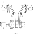
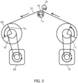
- a sheet processing apparatus is a sheet processing apparatus comprising: a storage unit that stores a sheet and feeds the sheet stored; and a control unit that controls the storage unit, characterized in that the storage unit comprises: a first reel around which a first tape is wound; a second reel around which a second tape is wound; a drum that winds the sheet together with the first tape drawn from the first reel and the second tape drawn from the second reel to form a roll; a first sensor that detects movement of the first tape; and a second sensor that detects movement of the second tape, a position at which the first tape is wound around the drum and a position at which the second tape is wound around the drum are different from each other in an axial direction of the drum, and the control unit controls the storage unit based on a detection result of the first sensor and a detection result of the second sensor.
- the control unit is capable of obtaining, based on the detection result of the first sensor, a size of the roll at the position at which the first tape is wound. Further, the control unit is capable of obtaining, based on the detection result of the second sensor, a size of the roll at the position at which the second tape is wound. Therefore, the control unit is capable of detecting that the shape of the roll is an inappropriate shape that is not a cylindrical shape being substantially uniform in diameter. In addition, when detecting that the shape of the roll is an inappropriate shape, the control unit is capable of controlling the storage unit suitably to that situation. It is thus possible, for example, to prevent deterioration of the situation or improve the situation.
- the sheet includes a banknote, check, ticket, coupon, and voucher.
- the first tape and the second tape may be wound around the drum while being in contact with the same surface of the sheet wound around the drum.
- the storage unit may comprise a third reel around which a third tape is wound, and a fourth reel around which a fourth tape is wound.
- the third tape is wound around the drum in such a manner as to overlap the first tape
- the fourth tape is wound around the drum in such a manner as to overlap the second tape.
- the third tape is wound around the drum in a state where the sheet is sandwiched between the third tape and the first tape
- the fourth tape is wound around the drum in a state where the sheet is sandwiched between the fourth tape and the second tape.
- the first tape and the second tape may be wound around the drum while in contact with respective different surfaces of the sheet wound around the drum.
- the first tape and the second tape do not overlap each other, but sandwiches the sheet from above and below. Therefore, when the drum, the first reel, and the second reel rotate reversely to unwind the roll, and the sheet comes out of the roll, the sheet cannot remain attached to the roll. In other words, it is possible to smoothly discharge the sheet from the storage unit.
- the storage unit may comprise a fifth reel around which a fifth tape is wound.
- the position at which the fifth tape is wound around the drum may be a position that is different in the axial direction of the drum from the position at which the first tape is wound and the position at which the second tape is wound.
- the position at which the fifth tape is wound may be on the opposite side of the position at which the first tape is wound, with the position at which the second tape is wound being interposed therebetween.
- the storage unit may comprise a fifth sensor for detecting the movement of the fifth tape. By using three of the first sensor, the second sensor, and the fifth sensor, it is possible to detect the shape of the roll more accurately. It is possible to detect that the roll has a barrel shape, for example.
- the storage unit may comprise at least one of a first roller and a second roller, the first roller being a roller which is in contact with the first tape stretched between the first reel and the drum and rotation of which is detected by the first sensor, the second roller being a roller which is in contact with the second tape stretched between the second reel and the drum and rotation of which is detected by the second sensor.
- the first roller may be disposed to be in contact with the first tape on a first tape path between the first reel and the drum along which the first tape is drawn from the first reel and reaches the drum.
- the second roller may be disposed to be in contact with the second tape on a second tape path between the second reel and the drum along which the second tape is drawn from the second reel and reaches the drum.
- the storage unit comprises the first roller, and the first sensor detects the rotation of the first roller. Accordingly, the first sensor is capable of reliably detecting the movement of the first tape.
- the storage unit comprises the second roller, and the second sensor detects the rotation of the second roller. Accordingly, the second sensor is capable of reliably detecting the movement of the second tape.
- At least one of the first tape and the second tape may be a tape that is given a repetitive mark throughout its length.
- the mark can be given by printing.
- the mark can also be given by forming the tape from a colored material.
- the first sensor may be a sensor that reads the mark given to the first tape.
- the second sensor may be a sensor that reads the mark given to the second tape.
- the amount of movement of the tape can be detected based on the number of passed marks.
- the moving speed of the tape can be detected based on the moving speed of the passed mark or the number of passed marks per unit time.
- the first sensor may be disposed at a position adjacent to the first tape stretched between the first reel and the drum, and the second sensor may be disposed at a position adjacent to the second tape stretched between the second reel and the drum.
- the first sensor may be disposed at a position adjacent to the first tape path and the second sensor may be disposed at a position adjacent to the second tape path.
- Such sensors are capable of detecting the movement of the tapes without making contact with the tapes.
- At least one of the first sensor and the second sensor may be a sensor for detecting the amount of movement of the tape.
- the control unit may calculate the moving speed of the tape from the amount of movement of the tape per unit time.
- at least one of the first sensor and the second sensor may be a sensor for directly detecting the moving speed of the tape.
- the first reel may be driven by a first motor
- the second reel may be driven by a second motor.
- the second motor is a different motor from the first motor. That is, the first reel and the second reel may be driven by the separate motors.
- a case is considered where a sheet is to be wound further in a state in which the roll has the shape of a truncated cone, specifically, in a state in which the diameter of the roll at the position at which the first tape is wound (hereinafter, sometimes referred to as the first position) is larger than the diameter of the roll at the position at which the second tape is wound (hereinafter, sometimes referred to as the second position).
- the first position the diameter of the roll at the position at which the first tape is wound
- the second position the diameter of the roll at the first position
- the first motor and the second motor are driven so that the tension applied to the first tape is greater than the tension applied to the second tape.
- the degree of increase in the diameter of the roll at the second position can be greater than the degree of increase in the diameter of the roll at the first position. That is, it is possible to gradually change the truncated cone shape into the cylindrical shape.
- the first reel and the second reel may be configured to be rotatable independently of each other by a single motor. That is, the motor may be configured such that the rotation of the single motor is transmitted via a transmission mechanism to the first reel and second reel at respective different transmission ratios. Examples of such a transmission mechanism may include a belt transmission mechanism using a pulley whose groove width is variable. With this configuration, it is possible to rotate the first reel and the second reel independently of each other using the single motor.
- the first reel and the second reel may be coaxially arranged. With such an arrangement, it is possible to equalize the distance from the first reel to the drum and the distance from the second reel to the drum, and thus to adjust the tension of the first tape and the tension of the second tape in the same manner.
- the first reel and the second reel may be arranged such that the axis of the first reel and the axis of the second reel are on respective different straight lines. With such an arrangement, it is possible to increase the degree of freedom in the layout of the first reel and the second reel, and thus to optimize the layout of elements constituting the storage unit.
- the drum may be driven by a drum motor.
- the drum motor is a different motor from the first motor for driving the first reel and the second motor for driving the second reel. With this configuration, it is possible to drive the drum independently of the first reel and the second reel. Driving the drum independently of the driving of each of the reels makes it possible to finely adjust the tension applied to the first tape and the second tape.
- the drum, the first reel, and the second reel may be configured to be rotatable independently of one another by a single motor. That is, the motor may be configured such that the rotation of the single motor is transmitted via a transmission mechanism to the drum, the first reel, and the second reel at respective different transmission ratios.
- the first motor may be a stepper motor. Using the stepper motor allows accurate control on the rotational angle (number of rotations) of the first motor and thus the rotational angle (number of rotations) of the first reel.
- the second motor may be a stepper motor. Using the stepper motor allows accurate control on the rotational angle (number of rotations) of the second motor and thus the rotational angle (number of rotations) of the second reel.
- the drum motor may be a stepper motor. Using the stepper motor allows accurate control on the rotational angle (number of rotations) of the drum motor and thus the rotational angle (number of rotations) of the drum.
- a sensor for detecting the rotational angle (number of rotations) of the first motor or the first reel may be disposed.
- a sensor for detecting the rotational angle (number of rotations) of the second motor or the second reel may be disposed.
- a sensor for detecting the rotational angle (number of rotations) of the drum motor or the drum may be
- the drum motor may be a DC motor.
- the sheet processing apparatus may comprise an inlet unit that lets the sheet in the inside of the sheet processing apparatus.
- the sheet processing apparatus may comprise a dispensing unit that dispenses the sheet to the outside of the sheet processing apparatus.
- the sheet processing apparatus may comprise a transport unit.
- the transport unit may be configured to transport the sheet between the inlet unit and the storage unit.
- the transport unit may be configured to transport the sheet between the storage unit and the dispensing unit.
- the sheet processing apparatus may comprise a recognition unit disposed to recognize the sheet being transported by the transport unit.
- the recognition unit may recognize the type or the transport orientation of the sheet.
- the transport orientation is a concept including the orientation of the face and the back of the sheet (for example, whether the face is oriented upward or downward) and the direction of the sheet.
- the transport orientation may be a concept including the position of the transported sheet in the width direction of the transport surface (in other words, in a direction orthogonal to the transport direction).
- the transport orientation may be a concept including an inclination of the sheet (whether or not the sheet is skewed) with respect to the transport direction.
- the transport orientation may be a concept including a relationship between the long edge and the short edge of a rectangular sheet and the transport direction (whether so-called short-edge leading transport or long-edge leading transport).
- the transport orientation relates to the position, in the axial direction of the drum, of a thick portion or a thin portion of a sheet not uniform in thickness during winding of the sheet around the drum.
- the recognition unit may recognize at least one of the denomination, fitness, authenticity, or degree of soiling of the banknotes.
- the control unit may control at least one of the inlet unit, the dispensing unit, the transport unit, and the recognition unit.
- the control unit may calculate, based on an output of the first sensor, a diameter or a radius of a portion of the roll at which the first tape is wound, and calculate, based on an output of the second sensor, a diameter or a radius of a portion of the roll at which the second tape is wound.
- the control unit controls the storage unit based on the calculated diameter or the calculated radius of the portion at which the first tape is wound and the calculated diameter or the calculated radius of the portion at which the second tape is wound.
- the control unit calculates the diameter or the radius of the portion of the roll at which the first tape is wound, based on the length of the first tape wound around the drum in a predetermined period and the rotational angle of the drum in this predetermined period. Further, the control unit calculates the diameter or the radius of the portion of the roll at which the second tape is wound, based on the length of second tape wound around the drum in a predetermined period and the rotational angle of the drum in this predetermined period.
- the control unit calculates, based on a detection result of the first sensor, the length of the first tape wound around the drum in the predetermined period.
- the control unit calculates, based on a detection result of the second sensor, the length of the second tape wound around the drum in the predetermined period.
- the control unit is capable of obtaining the rotational angle of the drum in the predetermined period based on the rotational angle of the motor driving the drum in the predetermined period.
- the rotational angle of the motor is the rotational angle of the drum.
- a transmission mechanism is interposed, a value obtained by multiplying the rotational angle of the motor by the transmission ratio is the rotational angle of the drum.
- the control unit is capable of obtaining the rotational angle of the drum by performing this operation.
- the rotational angle of the motor is obtainable from the number of steps when the motor is a stepper motor, or is obtainable from a detected value of a sensor such as an encoder mounted on a drive shaft of the motor when the motor is a DC motor.
- the control unit may control the storage unit based on a difference between the calculated diameter of the portion at which the first tape is wound and the calculated diameter of the portion at which the second tape is wound, or a difference between the calculated radius of the portion at which the first tape is wound and the calculated radius of the portion at which the second tape is wound.
- the control unit may control the storage unit based on whether or not the difference between the diameters or the difference between the radii exceeds a predetermined threshold.
- the control unit may control the storage unit based on a ratio between the calculated diameter of the portion at which the first tape is wound and the calculated diameter of the portion at which the second tape is wound, or a ratio between the calculated radius of the portion at which the first tape is wound and the calculated radius of the portion at which the second tape is wound.
- the control unit may control the storage unit based on whether or not the ratio between the diameters or the ratio between the radii exceeds a predetermined threshold.
- the predetermined threshold may be changed according to a change in size of the diameter or the radius of the roll. For example, the difference of 1 cm between the diameter at the first position and the diameter at the second position is assumed. With respect to this value of 1 cm, it is indicative that the truncated cone shape is more distinctive when the diameters of the roll are smaller than when the diameters of the roll are larger. That is, the difference or ratio between the diameter of the first position and the diameter of the second position which requires some countermeasures to be taken may be different depending on the sizes of the diameters of the roll. The same applies to the radius.
- the predetermined threshold may be set small when the diameters or the radii of the roll are small, or may be set largely when the diameters or the radii of the roll are large. Further, when it is to be determined whether or not the ratio between the diameters or the ratio between the radii exceeds a predetermined threshold, the predetermined threshold may be set small when the diameters or the radii of the roll are small, or may be set largely when the diameters or the radii of the roll are large.
- the control unit may calculate the moving speed of the first tape based on the output of the first sensor and calculate the moving speed of the second tape based on the output of the second sensor.
- the control unit controls the storage unit based on the calculated moving speed of the first tape and the calculated moving speed of the second tape.
- the moving speed of the first tape is proportional to the diameter of the roll at the first position.
- the moving speed of the second tape is proportional to the diameter of the roll at the second position.
- the control unit may calculate the moving speed of the first tape based on the length of the first tape wound by the drum in a unit time.
- the control unit may calculate the moving speed of the second tape based on the length of the second tape wound by the drum in a unit time.
- the control unit may control the storage unit based on a difference between the calculated moving speed of the first tape and the calculated moving speed of the second tape.
- the difference between the moving speeds of the tapes is proportional to the difference between the diameters or the radii of the roll at the positions at which the tapes are wound. Therefore, by controlling the storage unit based on the difference between the moving speeds, it is possible to obtain the same effect as in the case of controlling the storage unit based on the difference between the diameters or the radii of the roll.
- the control unit may control the storage unit based on whether or not the ratio between the moving speed of the first tape and the moving speed of the second tape exceeds a predetermined threshold.
- the control unit may control the storage unit based on whether or not the difference between the moving speeds or the ratio between the moving speeds exceeds a predetermined threshold.
- first tape or the second tape from shifting inside the storage unit from the original position at which the first tape or the second tape is wound under tension, to come off the first reel or the second reel or to become entangled inside the storage unit. Further, it is possible to prevent skew from being caused when the roll is unwound to discharge the sheet to the outside of the storage unit, so as to prevent clogging of the sheet due to the skew from being caused.
- a specific example of limitation of storage of sheets in the storage unit is prohibition of storage.
- the control unit may prohibit the storage of sheets in the storage unit not only when the outputs of the sensors indicate that the shape of the roll is an inappropriate shape, but also when such a shape is not indicated.
- the control unit may prohibit the storage of sheets in the storage unit when the outputs of the sensors indicate that the amount of banknotes stored in the storage unit has reached a predetermined upper limit.
- the control unit may prohibit the storage of banknotes of a predetermined denomination.
- the storage of banknotes of a denomination that are known in advance as the banknotes which are not uniform in thickness, such as those with a security thread or with a seal may be prohibited. Prohibition of the storage of such banknotes makes it possible to prevent the shape of the roll from becoming an inappropriate shape such as a truncated cone shape, or to prevent an increase in the degree of such a shape. Determination of whether or not the denomination is a predetermined denomination can be made based on a recognition result of the recognition unit.
- a unit from which a banknote is transported is a storage unit that separately stores banknotes for each denomination
- a destination to which the banknote is transported is a storage unit that collectively stores the banknotes of a plurality of denominations
- control unit may prohibit the storage of sheets soiled to a degree equal to or greater than a predetermined threshold.
- a predetermined threshold For example, as the degree of soiling increases, the surface of the sheets may become slippery. The slippery surface brings about a lower friction coefficient of the sheet. The sheet having a low friction coefficient is likely to slip with respect to the tape and other sheets with which the sheet having a low friction coefficient is in contact in the roll. Therefore, when a sheet soiled to a great degree is wound in the case where the roll has a truncated cone shape, the inner side and the outer side of the roll with respect to the sheet soiled to a great degree serving as a border are displaced from each other in the axial direction of the roll, and in some cases, the roll may collapse.
- Such a situation can be prevented from being caused by prohibiting the storage of sheets soiled to a degree equal to or greater than a predetermined threshold.
- the degree of soiling can be obtained from the recognition result of the recognition unit.
- a unit from which a sheet is transported is a storage unit that separately stores sheets for each degree of soiling
- a destination to which the sheet is transported is a storage unit that collectively stores the sheets regardless of the degree of soiling, it is possible to obtain the degree of soiling based on information indicating from which part of the storage unit the sheet is discharged.
- the predetermined transport orientation requiring limitation of storage in the storage unit is an orientation that increases a difference between the diameter of the roll at the position at which the first tape is wound and the diameter of the roll at the position at which the second tape is wound.
- the predetermined transport orientation is an orientation causing a thick portion of a sheet not uniform in thickness, such as a banknote with a security thread and a banknote with a seal, to be wound around at a portion of the roll greater in diameter.
- the sheet processing apparatus may comprise two or more storage units for storing sheets of the same type.
- the control unit may determine to which storage unit a sheet is stored, based on a detection result of a first sensor and a detection result of a second sensor of the first storage unit and a detection result of a first sensor and a detection result of a second sensor of the second storage unit.
- the control unit may further determine to which storage unit the sheet is stored, based on the transport orientation of the sheet.
- the control unit is capable of controlling the transport unit such that a sheet, storage of which in the first storage unit is limited because the transport orientation is a predetermined transport orientation, is transported to the second storage unit.
- the control unit may determine whether or not the storage amount of the storage unit has reached the upper limit, based on a larger one of the values of the diameter of the roll at the position at which the first tape is wound and the diameter of the roll at the position at which the second tape is wound, or a larger one of the values of the radius of the roll at the position at which the first tape is wound and the radius of the roll at the position at which the second tape is wound.
- the control unit may determine whether or not the storage amount of the storage unit has reached the lower limit, based on a smaller one of the values of the diameter of the roll at the position at which the first tape is wound and the diameter of the roll at the position at which the second tape is wound, or a smaller one of the values of the radius of the roll at the position at which the first tape is wound and the radius of the roll at the position at which the second tape is wound.
- the control unit recording the number of rotations that is the number of rotations of the drum for storing the sheets may determine that the storage unit is empty when the number of reverse rotations that is the number of rotations of the drum for discharging the stored sheets reaches the same number of rotations as the recorded number of rotations. Such determination makes it unnecessary to feed tape excessively in order to determine that the storage unit is empty, and it is thus possible to quickly proceed to the next winding operation.
- the control unit may adjust the rotational speed of the drum based on the detection result of the first sensor and the detection result of the second sensor.
- the control unit is capable of obtaining, based on the detection result of the first sensor and the detection result of the second sensor, the diameter or the radius of the roll at the position at which the first tape is wound and the diameter or the radius of the roll at the position at which the second tape is wound.
- the control unit is capable of controlling the drum, the first reel, and the second reel such that the tension of the first tape or the second tape wound at the position at which the diameter or the radius is small is reduced.
- the control unit may adjust the moving speeds of the first tape and the second tape, that is, the supply amounts of the first tape and the second tape to the drum by adjusting the number of rotations of at least one of the first reel and the second reel. For example, when the radius at the position at which the first tape is wound is greater than the radius at the position at which the second tape is wound, the length of the first tape wound during one rotation of the drum is longer than the length of the second tape wound.
- FIG. 1 is a block diagram illustrating a configuration of a banknote processing apparatus 1 that is an example of a sheet processing apparatus according to the present invention.
- the banknote processing apparatus 1 comprises an inlet unit 2, a transport unit 3, a recognition unit 4, a storage unit 5, and a control unit 6.
- the inlet unit 2 feeds banknotes put in or placed on the inlet unit 2 one by one to the transport unit 3.
- the recognition unit 4 recognizes the banknotes being transported by the transport unit 3. Specifically, the recognition unit 4 recognizes the denomination, fitness, transport orientation, authenticity, and the like of each of the banknotes.
- the storage unit 5 takes and stores therein the banknotes transported by the transport unit 3.
- An example of the storage unit 5 is a recycle storage unit.
- the banknote processing apparatus 1 may comprise a temporary storage unit as another example of the storage unit 5.
- the recycle storage unit is a storage unit in which banknotes are finally stored in a deposit process, and from which the banknotes are fed in a withdrawal process.
- the temporary storage unit is a storage unit that temporarily stores banknotes at the time of, for example, the deposit process or withdrawal process.
- the inlet unit 2, the transport unit 3, the recognition unit 4, and the storage unit 5 are controlled by the control unit 6.
- the banknote processing apparatus 1 may comprise a dispensing unit controlled by the control unit 6.
- the transport unit 3 can transport, to the dispensing unit, a banknote fed from the inlet unit 2 or a banknote fed from the storage unit 5.
- the banknote processing apparatus 1 may comprise a plurality of storage units 5 that are the recycle storage unit.
Landscapes
- Engineering & Computer Science (AREA)
- Mechanical Engineering (AREA)
- Controlling Rewinding, Feeding, Winding, Or Abnormalities Of Webs (AREA)
Claims (11)
- Bogenverarbeitungsvorrichtung (1), umfassend:eine Lagereinheit (5), die einen Bogen (S) lagert und den gelagerten Bogen zuführt; undeine Steuereinheit (6), die die Lagereinheit (5) steuert, wobei die Lagereinheit (5) umfasst:eine erste Rolle (11), um die herum ein erstes Band (12) gewickelt ist;eine zweite Rolle (21), um die herum ein zweites Band (22) gewickelt ist;eine Trommel (61), die den Bogen (S) zusammen mit dem ersten Band (12), das von der ersten Rolle (11) abgezogen wird, und dem zweiten Band (22), das von der zweiten Rolle (21) abgezogen wird, aufwickelt, um eine Rolle (62) zu bilden;einen ersten Sensor (15), der eine Bewegung des ersten Bandes (12) detektiert; undeinen zweiten Sensor (25), der eine Bewegung des zweiten Bandes (22) detektiert, undeine Position, an der das erste Band (12) um die Trommel (61) herum gewickelt ist, und eine Position, an der das zweite Band (22) um die Trommel (61) herum gewickelt ist, sind in einer Axialrichtung der Trommel (61) voneinander verschieden, unddie Steuereinheit (6) die Lagereinheit (5) basierend auf einem Detektionsergebnis des ersten Sensors (15) und einem Detektionsergebnis des zweiten Sensors (25) steuert,dadurch gekennzeichnet, dassdie Steuereinheit (6) mindestens eine von einer Spannung des ersten Bandes (12) und einer Spannung des zweiten Bandes (22) basierend auf dem Detektionsergebnis des ersten Sensors (15) und dem Detektionsergebnis des zweiten Sensors (25) einstellt.
- Bogenverarbeitungsvorrichtung (1) nach Anspruch 1, wobei
die Lagereinheit (5) ferner mindestens eine von einer ersten Walze (14) und einer zweiten Walze (24) umfasst, wobei die erste Walze (14) eine Walze ist, die mit dem zwischen der ersten Rolle (11) und der Trommel (61) gespannten ersten Band (12) in Kontakt steht und deren Drehung vom ersten Sensor (15) detektiert wird, wobei die zweite Walze (24) eine Walze ist, die mit dem zwischen der zweiten Rolle (21) und der Trommel (61) gespannten zweiten Band (22) in Kontakt steht und deren Drehung vom zweiten Sensor (25) detektiert wird. - Bogenverarbeitungsvorrichtung (1) nach Anspruch 1 oder 2, wobei
die erste Rolle (11) durch einen ersten Motor (13) angetrieben wird, und die zweite Rolle (21) durch einen zweiten Motor (23) angetrieben wird. - Bogenverarbeitungsvorrichtung (1) nach einem der Ansprüche 1 bis 3,
wobei
die Steuereinheit (6)basierend auf einer Ausgabe des ersten Sensors (15) einen Durchmesser oder einen Radius eines Abschnitts der Rolle (62), auf den das erste Band (12) gewickelt ist, berechnet, undbasierend auf einer Ausgabe des zweiten Sensors (25) einen Durchmesser oder einen Radius eines Abschnitts der Rolle (62), auf den das zweite Band (22) gewickelt ist, berechnet, unddie Lagereinheit (5) basierend auf dem berechneten Durchmesser oder dem berechneten Radius des Abschnitts, auf den das erste Band (12) gewickelt ist, und dem berechneten Durchmesser oder dem berechneten Radius des Abschnitts, auf den das zweite Band (22) gewickelt ist, steuert. - Bogenverarbeitungsvorrichtung (1) nach Anspruch 4, wobei
die Steuereinheit (6) die Lagereinheit (5) basierend auf einer Differenz zwischen dem berechneten Durchmesser des Abschnitts, auf den das erste Band (12) gewickelt ist, und dem berechneten Durchmesser des Abschnitts, auf den das zweite Band (22) gewickelt ist, oder einer Differenz zwischen dem berechneten Radius des Abschnitts, auf den das erste Band (12) gewickelt ist, und dem berechneten Radius des Abschnitts, auf den das zweite Band (22) gewickelt ist, steuert. - Bogenverarbeitungsvorrichtung (1) nach einem der Ansprüche 1 bis 3,
wobei
die Steuereinheit (6)eine Bewegungsgeschwindigkeit des ersten Bandes (12) basierend auf einer Ausgabe des ersten Sensors (15) berechnet,eine Bewegungsgeschwindigkeit des zweiten Bandes (22) basierend auf einer Ausgabe des zweiten Sensors (25) berechnet,die Lagereinheit (5) basierend auf der berechneten Bewegungsgeschwindigkeit des ersten Bandes (12) und der berechneten Bewegungsgeschwindigkeit des zweiten Bandes (22) steuert. - Bogenverarbeitungsvorrichtung (1) nach Anspruch 6, wobei
die Steuereinheit (6) die Lagereinheit (5) basierend auf einer Differenz zwischen der berechneten Bewegungsgeschwindigkeit des ersten Bandes (12) und der berechneten Bewegungsgeschwindigkeit des zweiten Bandes (22) steuert. - Bogenverarbeitungsvorrichtung (1) nach einem der Ansprüche 1 bis 7,
wobei
die Steuereinheit (6) die Lagerung des Bogens (S) in der Lagereinheit (5) basierend auf einer Ausgabe des ersten Sensors (15) und einer Ausgabe des zweiten Sensors (25) begrenzt. - Bogenverarbeitungsvorrichtung (1) nach einem der Ansprüche 1 bis 8,
wobei
die Steuereinheit (6) die Lagerung eines vorbestimmten Typs von Bogen (S) in der Lagereinheit (5) begrenzt. - Bogenverarbeitungsvorrichtung (1) nach einem der Ansprüche 1 bis 9,
wobei
die Steuereinheit (6) die Lagerung des Bogens (S), der eine vorbestimmte Transportausrichtung aufweist, in der Lagereinheit (5) begrenzt. - Bogenverarbeitungsvorrichtung (1) nach einem der Ansprüche 1 bis 10,
wobei
die Steuereinheit (6) eine Drehzahl der Trommel (61) basierend auf dem Detektionsergebnis des ersten Sensors (15) und dem Detektionsergebnis des zweiten Sensors (25) einstellt.
Priority Applications (1)
| Application Number | Priority Date | Filing Date | Title |
|---|---|---|---|
| EP21200492.3A EP4159654B1 (de) | 2021-10-01 | 2021-10-01 | Blattverarbeitungsvorrichtung |
Applications Claiming Priority (1)
| Application Number | Priority Date | Filing Date | Title |
|---|---|---|---|
| EP21200492.3A EP4159654B1 (de) | 2021-10-01 | 2021-10-01 | Blattverarbeitungsvorrichtung |
Publications (2)
| Publication Number | Publication Date |
|---|---|
| EP4159654A1 EP4159654A1 (de) | 2023-04-05 |
| EP4159654B1 true EP4159654B1 (de) | 2024-12-04 |
Family
ID=78293903
Family Applications (1)
| Application Number | Title | Priority Date | Filing Date |
|---|---|---|---|
| EP21200492.3A Active EP4159654B1 (de) | 2021-10-01 | 2021-10-01 | Blattverarbeitungsvorrichtung |
Country Status (1)
| Country | Link |
|---|---|
| EP (1) | EP4159654B1 (de) |
Family Cites Families (3)
| Publication number | Priority date | Publication date | Assignee | Title |
|---|---|---|---|---|
| EP2803608B1 (de) * | 2005-10-06 | 2016-04-06 | Crane Payment Innovations, Inc. | Banknotenspeicher |
| WO2016140139A1 (ja) * | 2015-03-05 | 2016-09-09 | グローリー株式会社 | 紙葉類繰出装置および紙葉類処理機 |
| CN108831007B (zh) * | 2018-06-04 | 2020-11-17 | 广州广电运通金融电子股份有限公司 | 一种纸币暂存装置 |
-
2021
- 2021-10-01 EP EP21200492.3A patent/EP4159654B1/de active Active
Also Published As
| Publication number | Publication date |
|---|---|
| EP4159654A1 (de) | 2023-04-05 |
Similar Documents
| Publication | Publication Date | Title |
|---|---|---|
| US8162308B2 (en) | Paper sheet processing device and method for controlling paper sheet processing device | |
| US6969064B2 (en) | Paper sheet storing and releasing apparatus | |
| EP2224403B1 (de) | Behälter-/zuführungseinrichtung für papiergeld | |
| EP1052211B1 (de) | Hülsenrohr für Bandrolle | |
| JP5475615B2 (ja) | 紙葉類収納繰出装置 | |
| JP4361821B2 (ja) | 紙葉類の斜行修正装置及び紙幣入出金装置 | |
| EP3798164B1 (de) | Blattbearbeitungsmaschine und blattverarbeitungsverfahren | |
| JPWO2010052795A1 (ja) | 紙葉類収納繰出装置 | |
| JP2016003095A (ja) | 紙葉類収納繰出装置および紙葉類処理方法 | |
| CN108463842A (zh) | 纸张类收纳机构及其控制方法 | |
| EP4159654B1 (de) | Blattverarbeitungsvorrichtung | |
| US8678387B2 (en) | Paper-sheet handling apparatus and paper-sheet handling method | |
| US10189670B2 (en) | Paper sheet handling machine and paper sheet handling method | |
| JP6539412B2 (ja) | 紙葉類収容装置及び紙葉類収容装置の制御方法 | |
| JP3351858B2 (ja) | 紙葉類計数装置 | |
| JP7158322B2 (ja) | 紙葉類収納装置及び紙葉類収納方法 | |
| KR20160011763A (ko) | 매체 처리 장치의 제어방법 | |
| JP6412623B1 (ja) | 紙葉還流装置、及び還流式紙葉取扱装置 | |
| KR101607387B1 (ko) | 매체 처리 장치의 제어방법 | |
| WO2018163649A1 (ja) | 紙葉類処理装置 | |
| JPH02282140A (ja) | 紙葉類連続繰出し装置 | |
| JPH11240646A (ja) | 紙葉類取扱装置 | |
| JPH05132174A (ja) | カード類の重送阻止装置 | |
| JP2018070271A (ja) | 紙葉類繰出装置および紙葉類処理機 |
Legal Events
| Date | Code | Title | Description |
|---|---|---|---|
| PUAI | Public reference made under article 153(3) epc to a published international application that has entered the european phase |
Free format text: ORIGINAL CODE: 0009012 |
|
| STAA | Information on the status of an ep patent application or granted ep patent |
Free format text: STATUS: REQUEST FOR EXAMINATION WAS MADE |
|
| 17P | Request for examination filed |
Effective date: 20211001 |
|
| AK | Designated contracting states |
Kind code of ref document: A1 Designated state(s): AL AT BE BG CH CY CZ DE DK EE ES FI FR GB GR HR HU IE IS IT LI LT LU LV MC MK MT NL NO PL PT RO RS SE SI SK SM TR |
|
| GRAP | Despatch of communication of intention to grant a patent |
Free format text: ORIGINAL CODE: EPIDOSNIGR1 |
|
| STAA | Information on the status of an ep patent application or granted ep patent |
Free format text: STATUS: GRANT OF PATENT IS INTENDED |
|
| INTG | Intention to grant announced |
Effective date: 20240510 |
|
| P01 | Opt-out of the competence of the unified patent court (upc) registered |
Free format text: CASE NUMBER: APP_38260/2024 Effective date: 20240627 |
|
| GRAS | Grant fee paid |
Free format text: ORIGINAL CODE: EPIDOSNIGR3 |
|
| GRAA | (expected) grant |
Free format text: ORIGINAL CODE: 0009210 |
|
| STAA | Information on the status of an ep patent application or granted ep patent |
Free format text: STATUS: THE PATENT HAS BEEN GRANTED |
|
| AK | Designated contracting states |
Kind code of ref document: B1 Designated state(s): AL AT BE BG CH CY CZ DE DK EE ES FI FR GB GR HR HU IE IS IT LI LT LU LV MC MK MT NL NO PL PT RO RS SE SI SK SM TR |
|
| REG | Reference to a national code |
Ref country code: CH Ref legal event code: EP |
|
| REG | Reference to a national code |
Ref country code: DE Ref legal event code: R096 Ref document number: 602021022747 Country of ref document: DE |
|
| REG | Reference to a national code |
Ref country code: IE Ref legal event code: FG4D |
|
| REG | Reference to a national code |
Ref country code: LT Ref legal event code: MG9D |
|
| REG | Reference to a national code |
Ref country code: NL Ref legal event code: MP Effective date: 20241204 |
|
| PG25 | Lapsed in a contracting state [announced via postgrant information from national office to epo] |
Ref country code: HR Free format text: LAPSE BECAUSE OF FAILURE TO SUBMIT A TRANSLATION OF THE DESCRIPTION OR TO PAY THE FEE WITHIN THE PRESCRIBED TIME-LIMIT Effective date: 20241204 |
|
| PG25 | Lapsed in a contracting state [announced via postgrant information from national office to epo] |
Ref country code: FI Free format text: LAPSE BECAUSE OF FAILURE TO SUBMIT A TRANSLATION OF THE DESCRIPTION OR TO PAY THE FEE WITHIN THE PRESCRIBED TIME-LIMIT Effective date: 20241204 |
|
| PG25 | Lapsed in a contracting state [announced via postgrant information from national office to epo] |
Ref country code: BG Free format text: LAPSE BECAUSE OF FAILURE TO SUBMIT A TRANSLATION OF THE DESCRIPTION OR TO PAY THE FEE WITHIN THE PRESCRIBED TIME-LIMIT Effective date: 20241204 |
|
| PG25 | Lapsed in a contracting state [announced via postgrant information from national office to epo] |
Ref country code: ES Free format text: LAPSE BECAUSE OF FAILURE TO SUBMIT A TRANSLATION OF THE DESCRIPTION OR TO PAY THE FEE WITHIN THE PRESCRIBED TIME-LIMIT Effective date: 20241204 |
|
| PG25 | Lapsed in a contracting state [announced via postgrant information from national office to epo] |
Ref country code: NO Free format text: LAPSE BECAUSE OF FAILURE TO SUBMIT A TRANSLATION OF THE DESCRIPTION OR TO PAY THE FEE WITHIN THE PRESCRIBED TIME-LIMIT Effective date: 20250304 |
|
| PG25 | Lapsed in a contracting state [announced via postgrant information from national office to epo] |
Ref country code: LV Free format text: LAPSE BECAUSE OF FAILURE TO SUBMIT A TRANSLATION OF THE DESCRIPTION OR TO PAY THE FEE WITHIN THE PRESCRIBED TIME-LIMIT Effective date: 20241204 Ref country code: GR Free format text: LAPSE BECAUSE OF FAILURE TO SUBMIT A TRANSLATION OF THE DESCRIPTION OR TO PAY THE FEE WITHIN THE PRESCRIBED TIME-LIMIT Effective date: 20250305 |
|
| PG25 | Lapsed in a contracting state [announced via postgrant information from national office to epo] |
Ref country code: RS Free format text: LAPSE BECAUSE OF FAILURE TO SUBMIT A TRANSLATION OF THE DESCRIPTION OR TO PAY THE FEE WITHIN THE PRESCRIBED TIME-LIMIT Effective date: 20250304 |
|
| PG25 | Lapsed in a contracting state [announced via postgrant information from national office to epo] |
Ref country code: NL Free format text: LAPSE BECAUSE OF FAILURE TO SUBMIT A TRANSLATION OF THE DESCRIPTION OR TO PAY THE FEE WITHIN THE PRESCRIBED TIME-LIMIT Effective date: 20241204 |
|
| REG | Reference to a national code |
Ref country code: AT Ref legal event code: MK05 Ref document number: 1747986 Country of ref document: AT Kind code of ref document: T Effective date: 20241204 |
|
| PG25 | Lapsed in a contracting state [announced via postgrant information from national office to epo] |
Ref country code: SM Free format text: LAPSE BECAUSE OF FAILURE TO SUBMIT A TRANSLATION OF THE DESCRIPTION OR TO PAY THE FEE WITHIN THE PRESCRIBED TIME-LIMIT Effective date: 20241204 |
|
| PG25 | Lapsed in a contracting state [announced via postgrant information from national office to epo] |
Ref country code: PL Free format text: LAPSE BECAUSE OF FAILURE TO SUBMIT A TRANSLATION OF THE DESCRIPTION OR TO PAY THE FEE WITHIN THE PRESCRIBED TIME-LIMIT Effective date: 20241204 |
|
| PG25 | Lapsed in a contracting state [announced via postgrant information from national office to epo] |
Ref country code: IS Free format text: LAPSE BECAUSE OF FAILURE TO SUBMIT A TRANSLATION OF THE DESCRIPTION OR TO PAY THE FEE WITHIN THE PRESCRIBED TIME-LIMIT Effective date: 20250404 |
|
| PG25 | Lapsed in a contracting state [announced via postgrant information from national office to epo] |
Ref country code: PT Free format text: LAPSE BECAUSE OF FAILURE TO SUBMIT A TRANSLATION OF THE DESCRIPTION OR TO PAY THE FEE WITHIN THE PRESCRIBED TIME-LIMIT Effective date: 20250404 |
|
| PG25 | Lapsed in a contracting state [announced via postgrant information from national office to epo] |
Ref country code: EE Free format text: LAPSE BECAUSE OF FAILURE TO SUBMIT A TRANSLATION OF THE DESCRIPTION OR TO PAY THE FEE WITHIN THE PRESCRIBED TIME-LIMIT Effective date: 20241204 |
|
| PG25 | Lapsed in a contracting state [announced via postgrant information from national office to epo] |
Ref country code: RO Free format text: LAPSE BECAUSE OF FAILURE TO SUBMIT A TRANSLATION OF THE DESCRIPTION OR TO PAY THE FEE WITHIN THE PRESCRIBED TIME-LIMIT Effective date: 20241204 Ref country code: AT Free format text: LAPSE BECAUSE OF FAILURE TO SUBMIT A TRANSLATION OF THE DESCRIPTION OR TO PAY THE FEE WITHIN THE PRESCRIBED TIME-LIMIT Effective date: 20241204 |
|
| PG25 | Lapsed in a contracting state [announced via postgrant information from national office to epo] |
Ref country code: SK Free format text: LAPSE BECAUSE OF FAILURE TO SUBMIT A TRANSLATION OF THE DESCRIPTION OR TO PAY THE FEE WITHIN THE PRESCRIBED TIME-LIMIT Effective date: 20241204 |
|
| PG25 | Lapsed in a contracting state [announced via postgrant information from national office to epo] |
Ref country code: CZ Free format text: LAPSE BECAUSE OF FAILURE TO SUBMIT A TRANSLATION OF THE DESCRIPTION OR TO PAY THE FEE WITHIN THE PRESCRIBED TIME-LIMIT Effective date: 20241204 |
|
| PG25 | Lapsed in a contracting state [announced via postgrant information from national office to epo] |
Ref country code: IT Free format text: LAPSE BECAUSE OF FAILURE TO SUBMIT A TRANSLATION OF THE DESCRIPTION OR TO PAY THE FEE WITHIN THE PRESCRIBED TIME-LIMIT Effective date: 20241204 |
|
| REG | Reference to a national code |
Ref country code: DE Ref legal event code: R097 Ref document number: 602021022747 Country of ref document: DE |
|
| PG25 | Lapsed in a contracting state [announced via postgrant information from national office to epo] |
Ref country code: SE Free format text: LAPSE BECAUSE OF FAILURE TO SUBMIT A TRANSLATION OF THE DESCRIPTION OR TO PAY THE FEE WITHIN THE PRESCRIBED TIME-LIMIT Effective date: 20241204 |
|
| PG25 | Lapsed in a contracting state [announced via postgrant information from national office to epo] |
Ref country code: DK Free format text: LAPSE BECAUSE OF FAILURE TO SUBMIT A TRANSLATION OF THE DESCRIPTION OR TO PAY THE FEE WITHIN THE PRESCRIBED TIME-LIMIT Effective date: 20241204 |
|
| PLBE | No opposition filed within time limit |
Free format text: ORIGINAL CODE: 0009261 |
|
| STAA | Information on the status of an ep patent application or granted ep patent |
Free format text: STATUS: NO OPPOSITION FILED WITHIN TIME LIMIT |
|
| 26N | No opposition filed |
Effective date: 20250905 |
|
| PGFP | Annual fee paid to national office [announced via postgrant information from national office to epo] |
Ref country code: DE Payment date: 20251021 Year of fee payment: 5 |