EP4159427B1 - Beutelherstellungsmaschine und beutelherstellungsverfahren - Google Patents
Beutelherstellungsmaschine und beutelherstellungsverfahren Download PDFInfo
- Publication number
- EP4159427B1 EP4159427B1 EP21810910.6A EP21810910A EP4159427B1 EP 4159427 B1 EP4159427 B1 EP 4159427B1 EP 21810910 A EP21810910 A EP 21810910A EP 4159427 B1 EP4159427 B1 EP 4159427B1
- Authority
- EP
- European Patent Office
- Prior art keywords
- web
- adhesive
- side section
- bag
- along
- Prior art date
- Legal status (The legal status is an assumption and is not a legal conclusion. Google has not performed a legal analysis and makes no representation as to the accuracy of the status listed.)
- Active
Links
Images


Classifications
-
- B—PERFORMING OPERATIONS; TRANSPORTING
- B31—MAKING ARTICLES OF PAPER, CARDBOARD OR MATERIAL WORKED IN A MANNER ANALOGOUS TO PAPER; WORKING PAPER, CARDBOARD OR MATERIAL WORKED IN A MANNER ANALOGOUS TO PAPER
- B31B—MAKING CONTAINERS OF PAPER, CARDBOARD OR MATERIAL WORKED IN A MANNER ANALOGOUS TO PAPER
- B31B70/00—Making flexible containers, e.g. envelopes or bags
- B31B70/14—Cutting, e.g. perforating, punching, slitting or trimming
- B31B70/16—Cutting webs
-
- B—PERFORMING OPERATIONS; TRANSPORTING
- B31—MAKING ARTICLES OF PAPER, CARDBOARD OR MATERIAL WORKED IN A MANNER ANALOGOUS TO PAPER; WORKING PAPER, CARDBOARD OR MATERIAL WORKED IN A MANNER ANALOGOUS TO PAPER
- B31B—MAKING CONTAINERS OF PAPER, CARDBOARD OR MATERIAL WORKED IN A MANNER ANALOGOUS TO PAPER
- B31B70/00—Making flexible containers, e.g. envelopes or bags
- B31B70/74—Auxiliary operations
- B31B70/81—Forming or attaching accessories, e.g. opening devices, closures or tear strings
- B31B70/813—Applying closures
- B31B70/8131—Making bags having interengaging closure elements
- B31B70/8132—Applying the closure elements in the machine direction
-
- B—PERFORMING OPERATIONS; TRANSPORTING
- B31—MAKING ARTICLES OF PAPER, CARDBOARD OR MATERIAL WORKED IN A MANNER ANALOGOUS TO PAPER; WORKING PAPER, CARDBOARD OR MATERIAL WORKED IN A MANNER ANALOGOUS TO PAPER
- B31B—MAKING CONTAINERS OF PAPER, CARDBOARD OR MATERIAL WORKED IN A MANNER ANALOGOUS TO PAPER
- B31B70/00—Making flexible containers, e.g. envelopes or bags
- B31B70/004—Closing bags
-
- B—PERFORMING OPERATIONS; TRANSPORTING
- B31—MAKING ARTICLES OF PAPER, CARDBOARD OR MATERIAL WORKED IN A MANNER ANALOGOUS TO PAPER; WORKING PAPER, CARDBOARD OR MATERIAL WORKED IN A MANNER ANALOGOUS TO PAPER
- B31B—MAKING CONTAINERS OF PAPER, CARDBOARD OR MATERIAL WORKED IN A MANNER ANALOGOUS TO PAPER
- B31B70/00—Making flexible containers, e.g. envelopes or bags
- B31B70/14—Cutting, e.g. perforating, punching, slitting or trimming
- B31B70/16—Cutting webs
- B31B70/18—Cutting webs longitudinally
-
- B—PERFORMING OPERATIONS; TRANSPORTING
- B31—MAKING ARTICLES OF PAPER, CARDBOARD OR MATERIAL WORKED IN A MANNER ANALOGOUS TO PAPER; WORKING PAPER, CARDBOARD OR MATERIAL WORKED IN A MANNER ANALOGOUS TO PAPER
- B31B—MAKING CONTAINERS OF PAPER, CARDBOARD OR MATERIAL WORKED IN A MANNER ANALOGOUS TO PAPER
- B31B70/00—Making flexible containers, e.g. envelopes or bags
- B31B70/26—Folding sheets, blanks or webs
- B31B70/262—Folding sheets, blanks or webs involving longitudinally folding, i.e. along a line parallel to the direction of movement
-
- B—PERFORMING OPERATIONS; TRANSPORTING
- B31—MAKING ARTICLES OF PAPER, CARDBOARD OR MATERIAL WORKED IN A MANNER ANALOGOUS TO PAPER; WORKING PAPER, CARDBOARD OR MATERIAL WORKED IN A MANNER ANALOGOUS TO PAPER
- B31B—MAKING CONTAINERS OF PAPER, CARDBOARD OR MATERIAL WORKED IN A MANNER ANALOGOUS TO PAPER
- B31B70/00—Making flexible containers, e.g. envelopes or bags
- B31B70/26—Folding sheets, blanks or webs
- B31B70/36—Folding sheets, blanks or webs by continuously feeding them to stationary members, e.g. plates, ploughs or cores
-
- B—PERFORMING OPERATIONS; TRANSPORTING
- B31—MAKING ARTICLES OF PAPER, CARDBOARD OR MATERIAL WORKED IN A MANNER ANALOGOUS TO PAPER; WORKING PAPER, CARDBOARD OR MATERIAL WORKED IN A MANNER ANALOGOUS TO PAPER
- B31B—MAKING CONTAINERS OF PAPER, CARDBOARD OR MATERIAL WORKED IN A MANNER ANALOGOUS TO PAPER
- B31B70/00—Making flexible containers, e.g. envelopes or bags
- B31B70/60—Uniting opposed surfaces or edges; Taping
- B31B70/62—Uniting opposed surfaces or edges; Taping by adhesives
-
- B—PERFORMING OPERATIONS; TRANSPORTING
- B31—MAKING ARTICLES OF PAPER, CARDBOARD OR MATERIAL WORKED IN A MANNER ANALOGOUS TO PAPER; WORKING PAPER, CARDBOARD OR MATERIAL WORKED IN A MANNER ANALOGOUS TO PAPER
- B31B—MAKING CONTAINERS OF PAPER, CARDBOARD OR MATERIAL WORKED IN A MANNER ANALOGOUS TO PAPER
- B31B70/00—Making flexible containers, e.g. envelopes or bags
- B31B70/60—Uniting opposed surfaces or edges; Taping
- B31B70/64—Uniting opposed surfaces or edges; Taping by applying heat or pressure
-
- B—PERFORMING OPERATIONS; TRANSPORTING
- B31—MAKING ARTICLES OF PAPER, CARDBOARD OR MATERIAL WORKED IN A MANNER ANALOGOUS TO PAPER; WORKING PAPER, CARDBOARD OR MATERIAL WORKED IN A MANNER ANALOGOUS TO PAPER
- B31B—MAKING CONTAINERS OF PAPER, CARDBOARD OR MATERIAL WORKED IN A MANNER ANALOGOUS TO PAPER
- B31B70/00—Making flexible containers, e.g. envelopes or bags
- B31B70/74—Auxiliary operations
- B31B70/81—Forming or attaching accessories, e.g. opening devices, closures or tear strings
-
- B—PERFORMING OPERATIONS; TRANSPORTING
- B65—CONVEYING; PACKING; STORING; HANDLING THIN OR FILAMENTARY MATERIAL
- B65D—CONTAINERS FOR STORAGE OR TRANSPORT OF ARTICLES OR MATERIALS, e.g. BAGS, BARRELS, BOTTLES, BOXES, CANS, CARTONS, CRATES, DRUMS, JARS, TANKS, HOPPERS, FORWARDING CONTAINERS; ACCESSORIES, CLOSURES, OR FITTINGS THEREFOR; PACKAGING ELEMENTS; PACKAGES
- B65D33/00—Details of, or accessories for, sacks or bags
- B65D33/06—Handles
- B65D33/08—Hand holes
-
- B—PERFORMING OPERATIONS; TRANSPORTING
- B65—CONVEYING; PACKING; STORING; HANDLING THIN OR FILAMENTARY MATERIAL
- B65D—CONTAINERS FOR STORAGE OR TRANSPORT OF ARTICLES OR MATERIALS, e.g. BAGS, BARRELS, BOTTLES, BOXES, CANS, CARTONS, CRATES, DRUMS, JARS, TANKS, HOPPERS, FORWARDING CONTAINERS; ACCESSORIES, CLOSURES, OR FITTINGS THEREFOR; PACKAGING ELEMENTS; PACKAGES
- B65D33/00—Details of, or accessories for, sacks or bags
- B65D33/16—End- or aperture-closing arrangements or devices
- B65D33/18—End- or aperture-closing arrangements or devices using adhesive applied to integral parts, e.g. to flaps
-
- B—PERFORMING OPERATIONS; TRANSPORTING
- B65—CONVEYING; PACKING; STORING; HANDLING THIN OR FILAMENTARY MATERIAL
- B65D—CONTAINERS FOR STORAGE OR TRANSPORT OF ARTICLES OR MATERIALS, e.g. BAGS, BARRELS, BOTTLES, BOXES, CANS, CARTONS, CRATES, DRUMS, JARS, TANKS, HOPPERS, FORWARDING CONTAINERS; ACCESSORIES, CLOSURES, OR FITTINGS THEREFOR; PACKAGING ELEMENTS; PACKAGES
- B65D33/00—Details of, or accessories for, sacks or bags
- B65D33/16—End- or aperture-closing arrangements or devices
- B65D33/24—End- or aperture-closing arrangements or devices using self-locking integral or attached closure elements, e.g. flaps
-
- B—PERFORMING OPERATIONS; TRANSPORTING
- B65—CONVEYING; PACKING; STORING; HANDLING THIN OR FILAMENTARY MATERIAL
- B65D—CONTAINERS FOR STORAGE OR TRANSPORT OF ARTICLES OR MATERIALS, e.g. BAGS, BARRELS, BOTTLES, BOXES, CANS, CARTONS, CRATES, DRUMS, JARS, TANKS, HOPPERS, FORWARDING CONTAINERS; ACCESSORIES, CLOSURES, OR FITTINGS THEREFOR; PACKAGING ELEMENTS; PACKAGES
- B65D33/00—Details of, or accessories for, sacks or bags
- B65D33/16—End- or aperture-closing arrangements or devices
- B65D33/25—Riveting; Dovetailing; Screwing; using press buttons or slide fasteners
- B65D33/2508—Riveting; Dovetailing; Screwing; using press buttons or slide fasteners using slide fasteners with interlocking members having a substantially uniform section throughout the length of the fastener; Sliders therefor
-
- B—PERFORMING OPERATIONS; TRANSPORTING
- B31—MAKING ARTICLES OF PAPER, CARDBOARD OR MATERIAL WORKED IN A MANNER ANALOGOUS TO PAPER; WORKING PAPER, CARDBOARD OR MATERIAL WORKED IN A MANNER ANALOGOUS TO PAPER
- B31B—MAKING CONTAINERS OF PAPER, CARDBOARD OR MATERIAL WORKED IN A MANNER ANALOGOUS TO PAPER
- B31B2155/00—Flexible containers made from webs
- B31B2155/001—Flexible containers made from webs by folding webs longitudinally
- B31B2155/0012—Flexible containers made from webs by folding webs longitudinally having their openings facing in the direction of movement
-
- B—PERFORMING OPERATIONS; TRANSPORTING
- B31—MAKING ARTICLES OF PAPER, CARDBOARD OR MATERIAL WORKED IN A MANNER ANALOGOUS TO PAPER; WORKING PAPER, CARDBOARD OR MATERIAL WORKED IN A MANNER ANALOGOUS TO PAPER
- B31B—MAKING CONTAINERS OF PAPER, CARDBOARD OR MATERIAL WORKED IN A MANNER ANALOGOUS TO PAPER
- B31B2160/00—Shape of flexible containers
- B31B2160/10—Shape of flexible containers rectangular and flat, i.e. without structural provision for thickness of contents
-
- B—PERFORMING OPERATIONS; TRANSPORTING
- B31—MAKING ARTICLES OF PAPER, CARDBOARD OR MATERIAL WORKED IN A MANNER ANALOGOUS TO PAPER; WORKING PAPER, CARDBOARD OR MATERIAL WORKED IN A MANNER ANALOGOUS TO PAPER
- B31B—MAKING CONTAINERS OF PAPER, CARDBOARD OR MATERIAL WORKED IN A MANNER ANALOGOUS TO PAPER
- B31B2160/00—Shape of flexible containers
- B31B2160/20—Shape of flexible containers with structural provision for thickness of contents
-
- B—PERFORMING OPERATIONS; TRANSPORTING
- B65—CONVEYING; PACKING; STORING; HANDLING THIN OR FILAMENTARY MATERIAL
- B65D—CONTAINERS FOR STORAGE OR TRANSPORT OF ARTICLES OR MATERIALS, e.g. BAGS, BARRELS, BOTTLES, BOXES, CANS, CARTONS, CRATES, DRUMS, JARS, TANKS, HOPPERS, FORWARDING CONTAINERS; ACCESSORIES, CLOSURES, OR FITTINGS THEREFOR; PACKAGING ELEMENTS; PACKAGES
- B65D2313/00—Connecting or fastening means
- B65D2313/02—Connecting or fastening means of hook-and-loop type
Definitions
- the present application relates to a bag making apparatus and a bag making method for making bags from a web and a continuous engagement tool.
- a bag such as a plastic bag includes, for example, an engagement tool such as a zipper or a hook-and-loop fastener.
- the bag can be freely opened and closed with the engagement tool.
- Patent document 1 discloses a bag with an engagement tool.
- the bag in Patent document 1 includes panel parts facing each other. Furthermore, adhesive is applied to the inner surfaces of both panel parts between an open edge of the bag and the engagement tool to peelably adhere the panel parts to each other.
- the bag is opened by the panel parts being peeled off from each other. After peeling, the bag can be opened and closed with the engagement tool.
- Such bags have been attracting attention because of their convenience.
- the panel parts of the bag in Patent document 1 may snugly overlap with each other near the open edge. In this case, it is hard to expand the open edge by pulling apart the panel part, and thus, hard to open the bag.
- US 2008/260305 A1 discloses an easy-open/reclosable bag including a first wall having an outer and inner surface; a second wall having an outer and inner surface; a bottom portion connecting the first and second walls; a first and second side seal; and a bag mouth; the first wall including a first folded edge portion including a first and second segment, a fold, and a PSA between the first and second segments; the outer surface of the first wall including an easy-open sealant; the outer surface of the second wall including an easy-open or regular sealant; and the inner surface of the first and second walls each including a regular sealant.
- US 2008/260305 A1 also discloses a method of making an easy-open/reclosable bag, and a package.
- An object of the present application is to provide a bag making apparatus and a bag making method for making bags which are easy to open.
- Patent document 1 JPH01-95033A
- a bag making apparatus for making bags from a web and a continuous engagement tool.
- the web has a first surface, a second surface, a first side section and a second side section.
- the continuous engagement tool includes a first member and a second member which are configured to be detachably engaged with each other.
- the bag making apparatus includes: an applicator configured to apply adhesive to at least one of the first side section or the second side section on the first surface in a longitudinal direction of the web; a first folding device configured to fold the web along two first fold lines extending in the longitudinal direction of the web such that the first and second side sections face the second surface; a second folding device configured to, after application of the adhesive and folding of the web along the two first fold lines, fold the web along a second fold line extending in the longitudinal direction of the web between the two first fold lines such that the first and second side sections face each other with the adhesive interposed therebetween; a welding device configured to weld the first and second members to the second surface in the longitudinal direction of the web; and a cross cut device configured to, after welding of the first and second members and folding of the web along the second fold line, cross-cut the web, the continuous engagement tool and the adhesive in a width direction of the web so as to make bags each having an open edge formed from two folded edges which result from the folding of the web along the two first fold lines.
- the bag making apparatus includes: an applicator configured to apply adhesive in a longitudinal direction of the web to the first side section on the first surface and/or to the second side section on the second surface; a first folding device configured to fold the web along a first fold line extending in the longitudinal direction of the web such that the first side section faces the second surface; a second folding device configured to, after application of the adhesive and folding of the web along the first fold line, fold the web along a second fold line extending in the longitudinal direction of the web such that the first and second side sections face each other with the adhesive interposed therebetween; a welding device configured to weld the first and second members to the second surface in the longitudinal direction of the web; and a cross cut device configured to, after welding of the first and second members and folding of the web along the second fold line, cross-cut the web, the continuous engagement tool and the adhesive in a width direction of the web so as to make bags each having an open edge including a folded edge which results from the folding of the web along the first fold line.
- the adhesive may be heat-sensitive adhesive.
- the bag making apparatus may further include a heat device configured to heat the heat-sensitive adhesive so as to peelably adhere the first and second side sections to each other via the heat-sensitive adhesive.
- the bag making apparatus may further include a slit device configured to slit the web along the second fold line after the folding of the web along the second fold line.
- a bag making method for making bags from a web and a continuous engagement tool for making bags from a web and a continuous engagement tool.
- the web has a first surface, a second surface, a first side section and a second side section.
- the continuous engagement tool includes a first member and a second member which are configured to be detachably engaged with each other.
- the bag making method includes: applying adhesive to at least one of the first side section or the second side section on the first surface in a longitudinal direction of the web; folding the web along two first fold lines extending in the longitudinal direction of the web such that the first and second side sections face the second surface; after application of the adhesive and folding of the web along the two first fold lines, folding the web along a second fold line extending in the longitudinal direction of the web between the two first fold lines such that the first and second side sections face each other with the adhesive interposed therebetween; welding the first and second members to the second surface in the longitudinal direction of the web; and after welding of the first and second members and folding of the web along the second fold line, cross-cutting the web, the continuous engagement tool and the adhesive in a width direction of the web to make bags each having an open edge formed from two folded edges which result from the folding of the web along the two first fold lines.
- the bag making method includes: applying adhesive in a longitudinal direction of the web to the first side section on the first surface and/or to the second side section on the second surface; folding the web along a first fold line extending in the longitudinal direction of the web such that the first side section faces the second surface; after application of the adhesive and folding of the web along the first fold line, folding the web along a second fold line extending in the longitudinal direction of the web such that the first and second side sections face each other with the adhesive interposed therebetween; welding the first and second members to the second surface in the longitudinal direction of the web; and after welding of the first and second members and folding of the web along the second fold line, cross-cut the web, the continuous engagement tool and the adhesive in a width direction of the web to make bags each having an open edge including a folded edge which results from the folding of the web along the first fold line.
- the adhesive may be heat-sensitive adhesive.
- the bag making method may further include heating the heat-sensitive adhesive to peelably adhere the first and second side sections to each other via the heat-sensitive adhesive.
- the bag making method further include slitting the web along the second fold line after the folding of the web along the second fold line.
- a bag not forming part of the invention but providing important background information for a better understanding of the invention, having an open edge and including: a first panel part and a first flap part which are formed by folding of a first sheet part; and a second panel part and a second flap part which are formed by folding of a second sheet part.
- the first and second panel parts face each other.
- the first and second flap parts are interposed between the first and second panel parts and face each other.
- the open edge is formed by a first folded edge of the first sheet part and a second folded edge of the second sheet part.
- the bag further includes an engagement tool interposed between the first and second panel parts and extending across widths of the first and second sheet parts.
- the engagement tool includes a first member and a second member which are configured to be detachably engaged with each other.
- the first member is disposed on the first panel part.
- the second member is disposed on the second panel part.
- the bag further includes adhesive located between the open edge and the engagement tool, interposed between the first and second flap parts and extending across the widths of the first and second sheet parts to peelably adhere the first and second flap parts to each other.
- the first folded edge may be shifted from the second folded edge in a direction away from the engagement tool.
- the bag may have a through hole located between the open edge and the adhesive and perpetrating through the first and second panel parts and the first and second flap parts.
- the bag may further include a handle formed by the first and second panel parts and the first and second flap parts between the through hole and the open edge.
- Another bag also not forming part of the invention but providing important background information for a better understanding of the invention, includes: a first panel part and a flap part which are formed by folding of a sheet part; and a second panel part, wherein the first and second panel parts face each other, wherein the flap part is interposed between the first and second parts, and wherein the open edge is formed by a folded edge of the sheet part and an end edge of the second panel part, the bag further including an engagement tool interposed between the first and second panel parts and extending across widths of the sheet part and the second panel part, the engagement tool including a first member and a second member which are configured to be detachably engaged with each other, the first member being disposed on the first panel part, the second member being disposed on the second panel part, the bag further including adhesive located between the open edge and the engagement tool, interposed between the flap part and the second panel part, and extending across the widths of the sheet part and the second panel part to peelably adhere the flap part and the second panel part to each other.
- the end edge of the second panel part may be shifted from the folded edge in a direction away from the engagement tool.
- the bag may have a through hole located between the open edge and the adhesive and perpetrating through the first and second panel parts and the flap part.
- the bag may further include a handle formed by the first and second panel parts and the flap part between the through hole and the open edge.
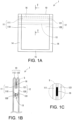
- FIG. 1A and FIG. 1B illustrate an example bag 1.
- FIG. 1B is a cross sectional view taken along the T-T line in FIG. 1A .
- the bag 1 has an open edge 10.
- the bag 1 further includes a first panel part 110 and a second panel part 120 facing each other.
- the bag 1 further includes a first flap part 111 and a second flap part 121 which are interposed between the panel parts 110 and 120 and face each other.
- the bag 1 includes a first sheet part 11 and a second sheet part 12.
- the sheet part 11 is folded along a fold line extending across the width of the sheet part 11.
- the panel part 110 and the flap part 111 are formed by this folding of the sheet part 11.
- the panel part 110 and the flap part 111 are formed as one piece.
- the sheet part 12 is folded along a fold line extending across the width of the sheet part 12.
- the panel part 120 and the flap part 121 are formed by this folding of the sheet part 12. In other words, the panel part 120 and the flap part 121 are formed as one piece.
- Each of the sheet parts 11 and 12 is a plastic film.
- the film may be a single-layer or multi-layer structure.
- the film of the multi-layer structure may include a base layer as one outer layer that functions as structural material, and a sealant layer as the other outer layer that functions as sealant.
- the film of the multi-layer structure may be used in such a manner that its base layer constitutes the outer surface of the panel part 110, 120, and its sealant layer constitutes the inner surface (facing surface) of the panel part 110, 120.
- each of the sheet parts 11 and 12 may include a base made of paper and a film or resin material laminated partially or fully to the base.
- the open edge 10 is formed by a first folded edge 112 resulting from folding of the first sheet part 11 and a second folded edge 122 resulting from folding of the second sheet part 12.
- the bag 1 includes an engagement tool 13 interposed between the panel parts 110 and 120 and extending across the widths of the sheet parts 11 and 12.
- the engagement tool 13 extends parallel to the open edge 10.
- the engagement tool 13 is located apart from the tips of the flap parts 111 and 121 in the direction away from the open edge 10. It is well-known that the bag 1 can be opened and closed freely with the engagement tool 13.
- the engagement tool 13 includes a first member 130 and a second member 131 which face each other and are configured to be detachably engaged with each other.
- the first member 130 is attached to the inner surface of the panel part 110 by means of welding, etc.
- the second member 131 is attached to the inner surface of the panel part 120 by means of welding, etc.
- the engagement tool 13 is a zipper.
- the member 130 is a male member
- the member 131 is a female member.
- the engagement tool 13 may be, for example, a hook-and-loop fastener instead.
- the bag 1 further includes side sealed sections 14 extending across the length of the bag 1 along the opposite side edges of the sheet parts 11 and 12.
- the side sealed sections 14 include: the portions in which the panel parts 110 and 120 are sealed to each other along the opposite side edges thereof except for the area where the flap parts 111 and 121 extend; the portions in which the panel part 110 and the flap part 111 are sealed to each other along the opposite side edges of the flap part 111; and the portions in which the panel part 120 and the flap part 121 are sealed to each other along the opposite side edges of the flap part 121.
- the flap parts 111 and 121 are not sealed to each other along the opposite side edges thereof.
- the side sealed sections 14 are not formed along the opposite side edges of the flap parts 111 and 121 between the flap parts 111 and 121.
- the side sealed sections 14 may further include portions in which the flap parts 111 and 121 are sealed to each other along the opposite side edges thereof.
- the bag 1 further includes a bottom sealed section 15 extending across the width of the bag 1 along the end edges of the sheet parts 11 and 12 (the panel parts 110 and 120) located opposite to the open edge 10.
- the bottom sealed section 15 consists of the portion in which the panel parts 110 and 120 are sealed to each other along the end edges thereof.
- FIG. 1C is an enlarged view of the region S in FIG. 1B .
- the bag 1 includes adhesive 16 interposed between the flap parts 111 and 121, located between the open edge 10 and the engagement tool 13, and extending across the widths of the sheet parts 11 and 12 to peelably adhere the flap parts 111 and 121 to each other.
- the adhesive 16 is part-coating.
- a user can expand the open edge 10 and peel off the flap parts 111 and 121 from each other against the adhesive strength of the adhesive 16, thereby opening the bag 1. After peeling off, a user can freely open and close the bag 1 using the engagement tool 13.
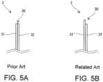
- FIG. 5A illustrates a partial cross section of the bag 3 according to the prior art disclosed in Patent document 1.
- the bag 3 includes panel parts 31 and 32, and an open edge 30 is formed by the end edges of the panel parts 31 and 32.
- the bag 3 also includes an engagement tool (not shown) and adhesive (not shown).
- FIG. 5A if the panel parts 31 and 32 snugly overlap with each other near the open edge 30, it is hard to expand the open edge 30 and thus hard to open the bag 3.
- FIG.1B a gap is formed by the folded edges 112 and 122 between these 112 and 122, which makes it easy to expand the open edge 10 and thus easy to open the bag 1.
- the open edge 30 may easily cause injury, such as cutting a finger by the open edge 30.
- the open edge 10 is constituted by the folded edges 112 and 122, it is less likely to cause injury by the open edge 10.
- the bag 1 has a thickness corresponding to four sheets (the total thickness of the parts 110, 111, 120 and 121) near the open edge 10. This facilitates holding the bag 1.
- the fact that the flap parts 111 and 121 are peelably adhered to each other via the adhesive 16 at this easy-to-hold location also improves easiness to open the bag 1.
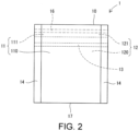
- FIG. 2 illustrates another example bag 1.
- the first sheet part 11 and the second sheet part 12 may be formed as one piece.
- a single sheet is folded along a fold line extending across the width of the sheet, and the sheet parts 11 and 12 are formed by this folding.
- the end edge located opposite to the open edge 10 is formed by an additional folded edge 17 which results from this folding of the single sheet.
- the bag 1 of FIG. 2 does not include the bottom sealed section 15 ( FIG. 1A ).
- FIG. 3 illustrates another example bag 1. As illustrated in FIG. 3 , one folded edge 112 may be shifted from the other folded edge 122 in the direction away from the engagement tool 13.
- the shift amount is, for example, 1 to 3 mm.
- FIG. 5B illustrates a partial cross section of a bag 3 according to the related art.
- This bag 3 is a variation of the bag 3 in FIG. 5A , in which the end edge of one panel part 13 is shifted with respect to the end edge of the other panel part 32 by, for example, 1 to 3 mm.
- the bag 3 in FIG. 5B makes it easier to pull apart the panel part 31, 32 at the open edge 30. It is clear from a comparison of FIG. 3 with FIG. 5B that the sheet parts 11 and 12 in FIG. 3 are much easier to be pulled apart near the open edge 10 than the bag 3 in FIG. 5B .
- FIG. 4A to FIG. 4C illustrate another example bag 1.
- FIG. 4B is a cross section taken along the P-P line in FIG. 4A
- FIG. 4C is a cross section taken along the Q-Q line in FIG. 4A .
- a through hole 18 is formed to penetrate through the panel parts 110 and 120 and the flap parts 111 and 121 between the open edge 110 and the engagement tool 13.
- a handle 19 is formed between the through hole 18 and the open edge 10 by the panel parts 110 and 120 as well as the flap parts 111 and 121.
- the handle 19 has a thickness corresponding to four sheets, and therefore, is sturdy and easy to hold.
- notches 20 may be formed on the opposite sides of the flap parts 111 and 121.
- Sealant 21 ( FIG. 4C ) may be filled into each notch 20, so that the panel parts 110 and 120 are sealed to each other via the filled sealant 21.
- the sealant layer of the multi-layer film constitutes the inner surface of each panel part 110, 120 as described above
- the sealant layers of the panel parts 110 and 120 are sealed to each other at the notches 20 as they face each other directly at the notches 20.
- the flap parts 111 and 121 are not sealed to each other along the opposite side edges thereof, each of the sheet parts 11 and 12 may flap towards the outside of the bag 1 in the area L where the flap parts 111 and 121 extend.
- the sealant 21 reduces this flapping.
- the above configuration is useful when the flap parts 111 and 121 are long in order to form the handle 19.
- holes may be formed in the flap parts 111 and 121.
- the notches 20 or the holes may be formed, for example, by means of punching the sheet parts 11 and 12 (the flap parts 111 and 121) in advance.
- the bag 1 may further include a restraining sealed section 22 extending across the widths of the sheet parts 11 and 12.
- the restraining sealed section 22 includes the portion in which the panel part 110 and the flap part 111 are sealed to each other in the tip of the flap part 111, and the portion in which the panel part 120 and the flap part 121 are heat-sealed to each other in the tip of the flap part 121. If the restraining sealed section 22 is not formed so that the tips of the flap parts 111 and 121 are not restrained as illustrated by the regions R in FIG. 4B , there is a possibility that, in taking out contents, the contents will enter between the panel part 110 and the flap part 111 and/or between the panel part 120 and the flap part 121 through the region(s) R. The restraining sealed section 22 prevents this.
- each example bag 1 may be incorporated into another example bag 1.
- the notches 20 or holes in FIG. 4A used for sealing the panel parts 110 and 120 to each other or the aforementioned restraining sealed section 22 may be included in the bag 1 with no handle in FIG. 1A .
- FIG. 6A illustrates the upstream section of the bag making apparatus 7.
- the bag making apparatus 7 include a feed device (not shown) that continuously unrolls a web 4 from a roll 4' and feeds the web 4 in the longitudinal direction of the web 4.
- the feed device includes, for example, at least one pair of feed rollers.
- the reference sign X 1 designates the feed direction.
- the web 4 has a first surface 40 and a second surface 41. In FIG. 6A , the web 4 is fed with the first surface 40 facing upward and the second surface 41 facing downward.
- the web 4 further has a first side section 42, a second side section 43, a first side edge 420, and a second side edge 430.
- the web 4 in the implementation is a plastic film.
- the film has a laminated structure, the surface 40 of which is formed by a base layer and the surface 41 of which is formed by a sealant layer having a lower melting point than that of the base layer.
- the base layer is OPP (biaxially oriented polypropylene), ONY (biaxially oriented nylon) or PET (biaxially oriented polypropylene), etc.
- the sealant layer is CPP (non-oriented polypropylene) or LDPE (low density polyethylene), etc.
- the web 4 may have a single-layer structure made of such material as polyethylene.
- the web 4 may include a base made of paper and a film or plastic material laminated partially or fully to the base.
- the bag making apparatus 7 may include a printer 70 that prints on the web 4.
- the printer 70 is disposed facing the surface 40 such that characters, figures, patterns, etc. are printed on the surface 40 of the web 4 using ink by the printer 70 while the web 4 is fed through the printer 70.
- An accumulator (not shown) may be disposed to ensure a feed distance enough to dry the ink.
- the bag making apparatus 7 includes an applicator 71 configured to apply adhesive 5 to the side sections 42 and 43 on the surface 40 along the longitudinal direction of the web 4.
- the applicator 71 in the implementation includes a first application unit 710 disposed facing the surface 40 to apply the adhesive 5 to the side section 42, and a second application unit 711 disposed facing the surface 40 to apply the adhesive 5 to the side section 43. While the web 4 is fed through the applicator 71, the adhesive 5 is applied to the side sections 42 and 43 by the application units 710 and 711, respectively. Thereby, the adhesive 5 is applied in the longitudinal direction of the web 4 as illustrated in FIG. 6C and FIG. 6D , which are enlarged views of the areas G and G' in FIG. 6A .
- Adhesive that develops its adhesive property upon being heated and is cured upon heat removal i.e., heat-sensitive adhesive is used as the adhesive in the implementation.
- the heat-sensitive adhesive in the implementation is part-coating.
- Part-coating may be, for example, solvent-based or water-based adhesive that is commonly available on the market.
- the heat-sensitive adhesive may be, for example, adhesive such as EVA (ethylene vinyl acetate)-based, olefinic-based, or polyamide (nylon)-based hot melt.
- the bag making apparatus 7 includes a first folding device 72 configured to fold the web 4 along two first fold lines 4a and 4b ( FIG. 6C, FIG. 6D ) extending in the longitudinal direction of the web 4, such that its side sections 42 and 43 face the surface 41.
- the first folding device 72 in the implementation is a well-known configuration including first, second, and third guide rollers 720, 721 and 722, as illustrated in FIG. 6A and FIG. 6B .
- the reference numerals 44 and 45 in FIG. 6A designate the folded edges resulting from folding of the web 4 along the fold lines 4a and 4b, respectively.
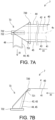
- FIG. 7A and FIG. 7B illustrate the midstream section of the bag making apparatus 7.
- the bag making apparatus 7 further includes a second folding device 73 configured to, after the above-mentioned application of the adhesive 5 and the folding of the web 4 along the fold lines 4a and 4b, fold the web 4 along a second fold line 4c ( FIG. 7A ) which extends in the longitudinal direction of the web 4 between the fold lines 4a and 4b.
- the second folding device 73 is a well-known guide device including a guide roller 730, a triangular plate 731, and suction rollers 732. As the web 4 is fed, it is guided by the guide roller 730, the triangular plate 731 and the suction rollers 732 to be folded along the fold line 4c and to cause the feed direction X 1 to be diverted by 90°.
- the fold line 4c in the implementation coincides with the longitudinal centerline of the web 4.
- the web 4 is folded in half by the second folding device 73 such that the side sections 42 and 43 face each other with the adhesive 5 interposed therebetween.
- the outer surface of the web 4 which has been folded in half is the surface 40 which is the base layer, and the inner surface of this web 4 is the surface 41 which is the sealant layer.
- the reference numeral 46 designates the folded edge resulting from folding of the web 4 along the fold line 4c.
- the folded edges 44, 45, and 46 may be heated for creasing.
- the adhesive 5 in the implementation has not yet adhered the side sections 42 and 43 to each other because it has not yet developed the adhesive property up to this step.
- the feed of the web 4 is appropriately converted from continuous feed to intermittent feed by a dancer device (not shown). Therefore, the web 4 is repeatedly paused and fed.
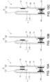
- FIG. 8A illustrates the downstream section of the bag making apparatus 7.
- the bag making apparatus 7 includes a heat device 74 configured to heat the adhesive 5 after folding of the web 4 along the fold line 4c (46) so as to peelably adhere the side sections 42 and 43 to each other via the adhesive 5 (not shown in FIG. 8A ).
- the heat device 74 heats the adhesive 5 sandwiched between the side sections 42 and 43 using a heater or heat seal bars, etc., thereby developing the adhesive property of the adhesive 5. This causes the adhesive 5 to peelably adhere the side sections 42 and 43 to each other.
- the heat device 74 in the implementation heats the adhesive at a temperature lower than the melting point of the sealant layer that constitutes the surface 41, to prevent melting of the sealant layer.
- the adhesive 5 has been selected in advance, which is capable of developing its adhesive property at a temperature lower than the melting point of the sealant layer.
- the heat device 74 heats the adhesive 5 at a temperature lower than the melting point of the single-layer film to prevent melting of the single-layer film.
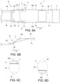
- the bag making apparatus 7 further includes a welding device 75 configured to supply a continuous engagement tool 6 to the web 4 in the longitudinal direction of the web 4 and to then weld the engagement tool 6 to the surface 41 of the web 4 in the longitudinal direction of the web 4.
- FIG. 8B illustrates a cross section of the continuous engagement tool 6.
- the engagement tool 6 includes a first member 60 and a second member 61 which are configured to be detachably engaged with each other.
- the engagement tool 6 in the implementation is a zipper made of plastic.
- the member 60 is a male member
- the member 61 is a female member.
- the welding device 75 in the implementation supplies the engagement tool 6 with the members 60 and 61 engaged with each other, and introduces it between the two layers of the folded web 4.
- the welding device 75 includes a guide unit (not shown) (such as extension rollers) that expands the two layers of the web 4 at the folded edges 44 and 45, and a guide roller 750 for guiding the engagement tool 6 and introducing the engagement tool 6 between the two layers of the web 4 through the area expanded by the guide unit.
- the welding device 75 further includes a welding unit 751 configured to weld the members 60 and 61 to the surface 41 of the web 4 in the longitudinal direction of the web 4 after the engagement tool 6 is introduced between the two layers of the web 4.
- the welding unit 751 welds the members 60 and 61 to the surface 41 by means of, for example, heat-sealing using a pair of heat seal bars or laser irradiation using a laser device.
- the member 60 is welded to one layer of the web 4, and the member 61 is welded to the other layer of web 4.
- the bag making apparatus 7 further includes a slitter 76 for slitting the web 4 along the fold line 4c ( FIG. 7A ), i.e., along the folded edge 46. As the web 4 is fed, it is slit in its longitudinal direction by the slitter 76. Thereby, an open edge 47 is formed. The waste 48 generated during this is wound up and collected.
- the bag making apparatus 7 further includes a cross seal device 77 configured to seal the web 4 in the width direction of the web 4 after folding of the web 4 along the fold line 4c.
- the cross seal device 77 in the implementation heat-seals the web 4, for example using a pair of heat seal bars, during every pause phase of the intermittent feed cycle. Since the surface 41, which is the sealant layer, constitutes the inner surface of the folded web 4, sealant layer of the surface 41 is melted by the cross seal device 77. Thus, the two layers of the web 4 are heat-sealed to each other. One layer of the web 4 and the side section 42 are heat-sealed to each other, and the other layer of the web 4 and the side section 43 are heat-sealed to each other. Thereby, a cross sealed section (not shown) is formed. In contrast, the side sections 42 and 43 are not heat-sealed to each other because their facing surfaces are formed by the surface 40, which is the base layer.
- the bag making apparatus 7 further includes a cross cut device 78 configured to cross-cut the web 4, the adhesive 5 and the engagement tool 6 in the width direction of the web 4 after welding of the members 60 and 61, folding of the web 4 along the fold line 4c, slitting of the web 4, and formation of the cross sealed section.
- the cross cut device 78 in the implementation cross-cuts the web 4, the adhesive 5 and the engagement tool 6 , for example using a cutter, in the width direction of the web 4 during every pause phase of the intermittent feed cycle.
- the position of cross-cutting is the position of the cross sealed section.
- a bag 1 is made every cross-cutting.
- the sheet parts 11 and 12 of the bag 1 are formed from two layers of the web 4.
- the flap parts 111 and 121 are formed from the side sections 42 and 43.
- the open edge 10 is (the folded edges 112 and 122 are) formed from the folded edges 44 and 45.
- the adhesive 16 is formed from the adhesive 5.
- the engagement tool 13 is formed from the engagement tool 6.
- Each of the side sealed sections 14 is formed from the cross sealed section.
- the open edge 22 ( FIG. 8A ) opposite to the open edge 10 is formed from the open edge 47. The contents may be filled through this open edge 22. After the filling, the bag 1 may be sealed along the open edge 22 such that the bottom sealed section 15 is formed.
- the aforementioned bags 1, which are easy to hold and open, are successively made.
- the adhesive 5 is applied to the first surface 40 which will form the outer surfaces of the bags 1.
- the step for applying the adhesive 5 and the step for printing on the web 4 can be carried out simultaneously at the same stage.
- the step for slitting the web 4 using the slitter 76 may be eliminated so that the bag 1 illustrated in FIG. 2 is made.
- the folded edge 17 ( FIG. 2 ) of the bag 1 is formed from the folded edge 46.
- the adhesive 5 may not be heated by the heat device 74.
- the contents may be filled into the bag 1 through the open edge 10, and then the adhesive 16 (formed from the adhesive 5) may be heated by another heat device to develop its adhesive property, thereby peelably adhering the flap parts 111 and 121 to each other.
- the application position of the applicator 71 and the positions of the fold lines 4a, 4b and 4c may be adjusted such that the folded edge 44 is shifted with respect to the folded edge 45 when the web 4 is folded along the fold line 4c.
- the application position of the applicator 71 and the fold lines 4a, 4b and 4c are properly adjusted to obtain sufficient lengths of the side sections 42 and 43. Then, the punching machine (not shown) of the bag making apparatus 7 punches a through hole, which corresponds to the through hole 18, in the web 4 before cross-cutting, or punches a hole 18 in the bag 1 after cross-cutting.
- the bag making apparatus may include a punching machine 79 configured to punch holes 421 and 431 ( FIG. 9B, FIG. 9C ) in the side sections 42 and 43.
- the punching machine 79 may include a first punching unit 790 configured to punch a first hole 421 in the side section 42 between the fold line 4a and the side edge 420, at a position not interfere with the adhesive 5, for example using a punching blade, and a second punching unit 791 configured to punch a second hole 431 in the side section 43 between the fold line 4b and the side edge 430 at a position not to interfere with the adhesive 5, for example using a punching blade.
- the bag making apparatus 7 may further include a longitudinal seal device (not shown) configured to heat-seal one layer of the web 4 and the side section 42 to each other, and the other layer of web 4 and the side section 43 to each other in the width direction of web 4 after folding of it along the fold line 4c.
- the longitudinal seal device performs heat-sealing, for example using a pair of heat seal bars, to form a longitudinal sealed section during every pause phase of the intermittent feed cycle.
- the side sections 42 and 43 are not sealed to each other at this time.
- the restraining sealed section 22 FIG. 4A
- the longitudinal sealed section is formed from the longitudinal sealed section.
- the bag 1 illustrated in FIG. 4A is made by the combination of the above respective steps.
- the applicator 71 may apply the adhesive 5 to only one of the side sections 42 and 43. Unlike the implementation, the adhesive 5 may be applied to at least one of the side sections 42 or 43 by the applicator 71 after the web 4 is folded by the first folding device 72.
- Adhesive e.g., viscous adhesive, other than heat-sensitive adhesive, may be used as adhesive 5, 16. In this case, when the web 4 is folded by the second folding device 73, the side sections 42 and 43 are peelably adhered to each other via the adhesive 5, without the step for heating the adhesive 5 using the heat device 74.
- FIG. 10A to FIG. 10C illustrate yet another example bag 1 in partial cross section.
- One of the differences from the aforementioned bag 1 is that one sheet part 11/12, e.g., the sheet part 12 is not folded.
- the sheet part 12 only consists of the panel part 120 and is not provided with any flap part. Only one flap part 111 is interposed between the panel parts 110 and 120.
- the open edge 10 is formed by the folded edge 112 of the sheet part 11 and the end edge 123 of the panel part 120.
- the engagement tool 13 extends across the widths of the sheet part 11 (panel part 110) and the panel part 120.
- the adhesive 16 is interposed between the flap part 111 and the panel part 120 and extends across the widths of the sheet part 11 (the panel part 110) and the panel part 12 to peelably adhere the flap part 111 and the panel part 120 to each other.
- the flap part 111 and the panel part 120 are separated from each other.
- the end edge 123 of the panel part 120 is shifted from the folded edge 112 in a direction away from the engagement tool 13. This further facilitates opening the bag.
- the bag 1 may have a through hole (not shown) located between the open edge 10 and the adhesive 16 and pretreating the panel parts 110 and 120 and the flap part 111, and may further include a handle (not shown) formed by the panel parts 110 and 120 and the flap part 111 between the through hole and the open edge 10. Also, the bag 1 in FIG. 10A to Fig. 10C may include the same additional features as those included in the aforementioned bags.
- the bag making apparatus makes the bags 1 illustrated in FIG.10A , it is configured as follows.
- the folding device 72 is configured to fold only one side section 42/43 of both side sections 42 and 43 of the web 4 along the fold line 4a/4b.
- the folding device 72 folds the side section 42 along the first fold line 4a, but does not fold the side section 43.
- the applicator 71 is configured to apply the adhesive 5 in the longitudinal direction of the web 4 to the side section 42 on the surface 40 using the application unit 710 and to the side section 43 (which is not folded) on the surface 41 using the application unit 711.
- the second folding device 73 is configured to fold it along the second fold line 4c such that the side sections 42 and 43 face each other with the adhesive 5 interposed therebetween.
- the subsequent configurations and steps are substantially the same as those in the aforementioned examples.
- the end edge 123 of the panel part 120 is formed from the side edge 430 of the web 4.
- Either one of the application units 710 and 711 may be dispensed with, and this case results in the bag 1 in FIG. 10B or FIG. 10C .
- viscose adhesive /a seal having an adhesive surface of viscose adhesive may be interposed between the first and second flap parts 111 and 121 by means of applying/affixing to peelably adhere the flap parts 111 and 121 to each other and to enable resealing the bag 1 after opening it. This extends the effectiveness of the desiccant or oxygen absorbing material packed, and contributes to restraining deterioration of the contents, such as food products.
- sealing at the notches 20 may be performed to prioritize the stability of the bag (to prevent the handle 19 from flapping) if the bag 1 in FIG. 4A is longitudinal in shape and the contents therein are also longitudinal in shape.
- sealing at the notches 20 may not be performed and the dimension of the area L may be set shorter so that the bag can be opened at the section which is right upper to the engagement tool 13, in order to prioritize easiness of taking out the contents.
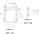
- FIG. 11A illustrates a reference example bag 9.
- the bag 9 in FIG. 11A is an improvement of the bag 3 according to the prior art in FIG. 5A .
- the method for making the bags 9 includes, before the step for forming the cross sealed section 93, locally toasting the edges 912 and 922 of the panel parts 91 and 92 (which constitute the open edge 90 of bag 9) in the predetermined range (2 ⁇ r1) that is centered on the position of cross-cutting, to make these edges rounded as illustrated in FIG. 11B and each have a maximum thickness t2 that is greater than the thickness t1 of the panel part 91, 92.
- the reference numeral 93 designates an engagement tool having the same configuration as the engagement tool 13 in the above examples.
- the reference numeral 95 designates a bottom sealed section having the same configuration as the bottom sealed section 15 in the above examples.
- the reference numeral 96 designates a peelable adhesive having the same configuration as the adhesive 16 in the above examples.
- FIG. 12A is an H line arrow view of FIG. 11A
- FIG. 12B is a J-J line cross section of FIG. 12A
- FIG. 12C is a K-K line cross section of FIG. 12A
- the portions each with the thickness t2 of the edges 912 and 922 in the sealed area are pressed against each other by the seal bars into a portion with a thickness t3 ( ⁇ 2 ⁇ t2).
- the portions each with the thickness t2 of the edges 912 and 922 have the remaining length (r1 - r2) and are located protruding from the cross sealed section 94 inward of the bag 9.
- the remaining portions each with the thickness t2 form a gap 900 between the panel parts 91 and 92 at the open edge 90 of the bag 9.
- This gap 900 facilitates peeling off the adhesive 96 by pinching the panel part 91, 92, and thus opening the bag 9.
- a gap 900 that facilitates opening the bag 9 is formed by the fuse-cut edge 94' resulting from fusion cutting.
- the advantages of a bag with a zipper and part-coating/hot melt over a bag with a zipper and a notch are as follows.
- Bag with a notch In the manufacturing step, after creating a notch serving as a trigger for tearing, it requires a scoring process using a laser or a process for cutting the film by approximately half of its thickness in advance in order the tear line to be parallel to the zipper. Furthermore, in order to make the strength of the film have orientations, it is sometimes strengthened or weaken in advance in the direction in which it can extend. Thus, the burden on manufacturing is unexpectedly large.
- Bag with part-coating/hot melt does not require the above processes for the bag with a notch, as it does not require tearing for opening thereof. In addition, it does not require giving the strength of the film the orientations, and the film having uniform strength can be used without any problems. Consequently, a thin film can be used, leading to eco-friendliness.
Landscapes
- Engineering & Computer Science (AREA)
- Mechanical Engineering (AREA)
- Making Paper Articles (AREA)
- Bag Frames (AREA)
Claims (8)
- Beutelherstellungsvorrichtung (7) zum Herstellen von Beuteln (1) aus einer Bahn (4) und einem kontinuierlichen Eingriffswerkzeug (6), wobei die Bahn (4) eine erste Fläche (40), eine zweite Fläche (41), einen ersten Seitenabschnitt (42) und einen zweiten Seitenabschnitt (43) aufweist, wobei das kontinuierliche Eingriffswerkzeug (6) ein erstes Element (60) und ein zweites Element (61) umfasst, die konfiguriert sind, um lösbar miteinander in Eingriff gebracht zu werden,
wobei die Beutelherstellungsvorrichtung (7) umfasst:einen Applikator (71), die konfiguriert ist, um Klebstoff (5) auf mindestens einen des ersten Seitenabschnitts (42) oder des zweiten Seitenabschnitts (43) auf der ersten Fläche (40) in einer Längsrichtung der Bahn (4) aufzutragen;eine erste Faltvorrichtung (72), die konfiguriert ist, um die Bahn (4) entlang zweier erster Faltlinien (4a, 4b) zu falten, die sich in der Längsrichtung der Bahn (4) erstrecken, so dass der erste Seitenabschnitt (42) und der zweite Seitenabschnitt (43) der zweiten Fläche (41) gegenüberliegen;eine zweite Faltvorrichtung (73), die konfiguriert ist, um nach Auftragen des Klebstoffs (5) und Falten der Bahn (4) entlang der beiden ersten Faltlinien (4a, 4b) die Bahn (4) entlang einer zweiten Faltlinie (4c) zu falten, die sich in der Längsrichtung der Bahn (4) zwischen den beiden ersten Faltlinien (4a, 4b) erstreckt, so dass der erste Seitenabschnitt (42) und der zweite Seitenabschnitt (43) einander zugewandt sind, wobei der Klebstoff (5) dazwischen angeordnet ist;eine Schweißvorrichtung (75), die konfiguriert ist, um das erste Element (60) und das zweite Element (61) mit der zweiten Fläche (41) in der Längsrichtung der Bahn (4) zu verschweißen; undeine Querschneidevorrichtung (78), die konfiguriert ist, um nach Verschweißen des ersten Elements (60) und des zweiten Elements (61) und Falten der Bahn (4) entlang der zweiten Faltlinie (4c) die Bahn (4), das kontinuierliche Eingriffswerkzeug (13) und den Klebstoff (5, 16) in einer Breitenrichtung der Bahn (4) quer zu schneiden, um Beutel (1) herzustellen, die jeweils einen offenen Rand (10) aufweisen, der aus zwei gefalteten Rändern (112, 122) gebildet ist, die aus dem Falten der Bahn (4) entlang der zwei ersten Faltlinien (4a, 4b) resultieren. - Beutelherstellungsvorrichtung (7) zur Herstellung von Beuteln (1) aus einer Bahn (4) und einem kontinuierlichen Eingriffswerkzeug (6), wobei die Bahn (4) eine erste Fläche (40), eine zweite Fläche (41), einen ersten Seitenabschnitt (42) und einen zweiten Seitenabschnitt (43) aufweist, wobei das kontinuierliche Eingriffswerkzeug (6) ein erstes Element (60) und ein zweites Element (61) umfasst, die konfiguriert sind, um lösbar miteinander in Eingriff gebracht zu werden,
wobei die Beutelherstellungsvorrichtung (7) umfasst:einen Applikator (71), der konfiguriert ist, um Klebstoff (5) in einer Längsrichtung der Bahn (4) auf den ersten Seitenabschnitt (42) auf der ersten Fläche (40) und/oder auf den zweiten Seitenabschnitt (43) auf der zweiten Fläche (41) aufzutragen;eine erste Faltvorrichtung (72), die konfiguriert ist, um die Bahn (4) entlang einer ersten Faltlinie (4a) zu falten, die sich in der Längsrichtung der Bahn (4) erstreckt, so dass der erste Seitenabschnitt (42) der zweiten Fläche (41) zugewandt ist;eine zweite Faltvorrichtung (73), die konfiguriert ist, um nach Auftragen des Klebstoffs (5) und Falten der Bahn (4) entlang der ersten Faltlinie (4a) die Bahn (4) entlang einer zweiten Faltlinie (4c) zu falten, die sich in der Längsrichtung der Bahn (4) erstreckt, so dass der erste Seitenabschnitt (42) und der zweite Seitenabschnitt (43) einander zugewandt sind, wobei der Klebstoff (5) dazwischen angeordnet ist;eine Schweißvorrichtung (75), die konfiguriert ist, um das erste Element (60) und das zweite Element (61) mit der zweiten Fläche (41) in der Längsrichtung der Bahn (4) zu verschweißen; undeine Querschneidevorrichtung (78), die konfiguriert ist, um nach Verschweißen des ersten Elements (60) und des zweiten Elements (61) und Falten der Bahn (4) entlang der zweiten Faltlinie (4c) die Bahn (4), das kontinuierliche Eingriffswerkzeug (13) und den Klebstoff (5, 16) in einer Breitenrichtung der Bahn (4) quer zu schneiden, um Beutel (1) herzustellen, die jeweils einen offenen Rand (10) mit einem gefalteten Rand (112) aufweisen, die aus dem Falten der Bahn (4) entlang der ersten Faltlinie (4a) resultiert. - Beutelherstellungsvorrichtung (7) gemäß Anspruch 1 oder 2, wobei der Klebstoff (5) ein wärmeempfindlicher Klebstoff ist, und
wobei die Beutelherstellungsvorrichtung (7) ferner eine Wärmevorrichtung (74) umfasst, die konfiguriert ist, um den wärmeempfindlichen Klebstoff zu erwärmen, um den ersten Seitenabschnitt (42) und den zweiten Seitenabschnitt (43) über den wärmeempfindlichen Klebstoff ablösbar aneinander zu kleben. - Beutelherstellungsvorrichtung (7) gemäß einem der Ansprüche 1 bis 3, die ferner eine Schlitzvorrichtung (76) umfasst, die konfiguriert ist, um die Bahn (4) nach dem Falten der Bahn (4) entlang der zweiten Faltlinie (4c) zu schlitzen.
- Beutelherstellungsverfahren zum aufeinanderfolgenden Herstellen von Beuteln (1) aus einer Bahn (4) und einem kontinuierlichen Eingriffswerkzeug (6), wobei die Bahn (4) eine erste Fläche (40), eine zweite Fläche (41), einen ersten Seitenabschnitt (42) und einen zweiten Seitenabschnitt (43) aufweist, wobei das kontinuierliche Eingriffswerkzeug (6) ein erstes Element (60) und ein zweites Element (61) umfasst, die konfiguriert sind, um lösbar miteinander in Eingriff gebracht zu,
wobei das Beutelherstellungsverfahren umfasst:Zuführen der Bahn (4) in einer Längsrichtung der Bahn (4);während Zuführen der Bahn (4), Auftragen von Klebstoff (5) auf mindestens einen des ersten Seitenabschnitts (42) oder des zweiten Seitenabschnitts (43) auf der ersten Fläche (40) in der Längsrichtung der Bahn (4);Falten der Bahn (4) entlang zweier erster Faltlinien (4a, 4b), die sich in Längsrichtung der Bahn (4) erstrecken, während die Bahn (4) zugeführt wird, so dass der erste Seitenabschnitt (42) und der zweite Seitenabschnitt (43) der zweiten Fläche (41) zugewandt sind;nach Auftragen des Klebstoffs (5) und Falten der Bahn (4) entlang der beiden ersten Faltlinien (4a, 4b), Falten der Bahn (4) entlang einer zweiten Faltlinie (4c), die sich in der Längsrichtung der Bahn (4) zwischen den beiden ersten Faltlinien (4a, 4b) erstreckt, während die Bahn (4) zugeführt wird, so dass der erste Seitenabschnitt (42) und der zweite Seitenabschnitt (43) einander zugewandt sind, wobei der Klebstoff (5) dazwischen liegt;Schweißen des ersten Elements (60) und des zweiten Elements (61) an die zweite Fläche (41) in der Längsrichtung der Bahn (4); undnach Schweißen des ersten Elements (60) und des zweiten Elements (61) und Falten der Bahn (4) entlang der zweiten Faltlinie (4c), Querschneiden der Bahn (4), des kontinuierlichen Eingriffswerkzeugs (13) und des Klebstoffs (16) in einer Breitenrichtung der Bahn (4), um bei jedem Querschneiden einen Beutel (1) herzustellen, wobei der Beutel (1) einen offenen Rand (10) aufweist, der aus zwei gefalteten Rändern (112, 122) gebildet ist, die aus dem Falten der Bahn (4) entlang der zwei ersten Faltlinien (4a, 4b) resultieren. - Beutelherstellungsverfahren zum aufeinanderfolgenden Herstellen von Beuteln (1) aus einer Bahn (4) und einem kontinuierlichen Eingriffswerkzeug (6), wobei die Bahn (4) eine erste Fläche (40), eine zweite Fläche (41), einen ersten Seitenabschnitt (42) und einen zweiten Seitenabschnitt (43) aufweist, wobei das kontinuierliche Eingriffswerkzeug (6) ein erstes Element (60) und ein zweites Element (61) umfasst, die konfiguriert sind, um lösbar miteinander in Eingriff gebracht zu werden,
wobei das Beutelherstellungsverfahren umfasst:Zuführen der Bahn (4) in einer Längsrichtung der Bahn (4);während Zuführen der Bahn (4), Auftragen von Klebstoff (5) in der Längsrichtung der Bahn (4) auf den ersten Seitenabschnitt (42) auf der ersten Fläche (40) und/oder auf den zweiten Seitenabschnitt (43) auf der zweiten Fläche (41);Falten der Bahn (4) entlang einer ersten Faltlinie (4a), die sich in Längsrichtung der Bahn (4) erstreckt, während die Bahn (4) zugeführt wird, so dass der erste Seitenabschnitt (42) der zweiten Fläche (41) zugewandt ist;nach Auftragen des Klebstoffs (5) und Falten der Bahn (4) entlang der ersten Faltlinie (4a), Falten der Bahn (4) entlang einer zweiten Faltlinie (4c), die sich in der Längsrichtung der Bahn (4) erstreckt, wenn die Bahn (4) zugeführt wird, so dass der erste Seitenabschnitt (42) und der zweite Seitenabschnitt (43) einander zugewandt sind, wobei der Klebstoff (5) dazwischen angeordnet ist;Schweißen des ersten Elements (60) und des zweiten Elements (61) an die zweite Fläche (41) in der Längsrichtung der Bahn (4); undnach Schweißen des ersten Elements (60) und des zweiten Elements (61) und Falten der Bahn (4) entlang der zweiten Faltlinie (4c), Querschneiden der Bahn (4), des kontinuierlichen Eingriffswerkzeugs (13) und des Klebstoffs (16) in einer Breitenrichtung der Bahn (4), um bei jedem Querschneiden einen Beutel (1) herzustellen, wobei der Beutel (1) einen offenen Rand (10) einschließlich eines gefalteten Rands (112) aufweist, die aus dem Falten der Bahn (4) entlang der ersten Faltlinie (4a) resultiert. - Beutelherstellungsverfahren gemäß Anspruch 5 oder 6, wobei der Klebstoff (5) ein wärmeempfindlicher Klebstoff ist, und
wobei das Beutelherstellungsverfahren ferner Erwärmen des wärmeempfindlichen Klebstoffs umfasst, um den ersten Seitenabschnitt (42) und den zweiten Seitenabschnitt (43) über den wärmeempfindlichen Klebstoff ablösbar aneinander zu kleben. - Beutelherstellungsverfahren gemäß einem der Ansprüche 5 bis 7, ferner umfassend Schlitzen der Bahn (4) entlang der zweiten Faltlinie (4c) nach dem Falten der Bahn (4) entlang der zweiten Faltlinie (4c).
Applications Claiming Priority (2)
| Application Number | Priority Date | Filing Date | Title |
|---|---|---|---|
| JP2020094568 | 2020-05-29 | ||
| PCT/JP2021/018783 WO2021241328A1 (ja) | 2020-05-29 | 2021-05-18 | 製袋機、製袋方法、および、袋 |
Publications (3)
| Publication Number | Publication Date |
|---|---|
| EP4159427A1 EP4159427A1 (de) | 2023-04-05 |
| EP4159427A4 EP4159427A4 (de) | 2023-12-20 |
| EP4159427B1 true EP4159427B1 (de) | 2024-11-27 |
Family
ID=78744536
Family Applications (1)
| Application Number | Title | Priority Date | Filing Date |
|---|---|---|---|
| EP21810910.6A Active EP4159427B1 (de) | 2020-05-29 | 2021-05-18 | Beutelherstellungsmaschine und beutelherstellungsverfahren |
Country Status (5)
| Country | Link |
|---|---|
| US (1) | US12226975B2 (de) |
| EP (1) | EP4159427B1 (de) |
| JP (1) | JP7168184B2 (de) |
| CN (1) | CN115485132B (de) |
| WO (1) | WO2021241328A1 (de) |
Family Cites Families (33)
| Publication number | Priority date | Publication date | Assignee | Title |
|---|---|---|---|---|
| US4055109A (en) * | 1975-08-04 | 1977-10-25 | Dai Nippon Insatsu Kabushiki Kaisha | Method and apparatus for producing self-standing bags |
| JPH0195033A (ja) | 1987-10-07 | 1989-04-13 | Seisan Nipponsha Kk | 粘着層を有する咬合具の製造方法 |
| JP2941507B2 (ja) | 1991-08-14 | 1999-08-25 | 株式会社東芝 | 図形情報二値化装置 |
| JP2550414Y2 (ja) * | 1991-11-28 | 1997-10-15 | 日本特許管理株式会社 | ジッパー付袋 |
| WO1993010980A1 (en) * | 1991-11-29 | 1993-06-10 | Long, John, Albert | Continuous form and apparatus for forming letter sheets therefrom |
| US5769773A (en) * | 1996-04-23 | 1998-06-23 | De Santo; Ronald F. | Paper product and related method |
| JP3052894U (ja) * | 1998-04-03 | 1998-10-09 | 朋和産業株式会社 | 咬合具付き包装袋 |
| US6503182B2 (en) * | 2001-03-29 | 2003-01-07 | Zsolt Design Engineering, Inc. | Compact apparatus and system for creating and dispensing cushioning dunnage |
| JP2004001402A (ja) * | 2002-02-27 | 2004-01-08 | Seibu Kikai Kk | 袋の製造装置及び袋の製造方法 |
| JP2005225542A (ja) * | 2004-02-16 | 2005-08-25 | Daiwa Gravure Co Ltd | ジッパー付き包装袋 |
| JP4876473B2 (ja) | 2005-08-04 | 2012-02-15 | 住友ベークライト株式会社 | 包装袋 |
| US10814577B2 (en) * | 2006-08-11 | 2020-10-27 | Gregorio Lim Tan | Self opening wide mouth carryout bag pack, apparatus and method of making same |
| US20080260305A1 (en) * | 2007-04-20 | 2008-10-23 | Shah Gautam P | Easy-open/reclosable bag and package |
| AU2008364073B2 (en) * | 2008-11-13 | 2011-08-25 | Totani Corporation | Plastic bag making apparatus |
| JP5749939B2 (ja) * | 2011-03-02 | 2015-07-15 | 株式会社イシダ | 製袋包装機 |
| US9272481B2 (en) * | 2012-12-06 | 2016-03-01 | Innoflex Incorporated | Bottom-gusseted package and method |
| JP6111640B2 (ja) * | 2012-12-13 | 2017-04-12 | 凸版印刷株式会社 | 詰替え容器の製造方法 |
| JP5323249B1 (ja) * | 2012-12-28 | 2013-10-23 | トタニ技研工業株式会社 | 製袋機 |
| JP6178636B2 (ja) * | 2013-06-24 | 2017-08-09 | 出光ユニテック株式会社 | 袋体およびその製造方法 |
| ES2910057T3 (es) * | 2013-09-23 | 2022-05-11 | Innoflex Incorporated | Empaque y método con fuelle inferior |
| WO2015178318A1 (ja) * | 2014-05-21 | 2015-11-26 | 出光ユニテック株式会社 | ジッパーテープ付袋体、ジッパーテープ付袋体の物品収納方法、ジッパーテープ付袋体の製造方法、および、ジッパーテープ付袋体の製造装置 |
| US20160311580A1 (en) * | 2014-05-26 | 2016-10-27 | Mupack Ozaki Co., Ltd. | Packing bag |
| JP6259416B2 (ja) * | 2015-04-01 | 2018-01-10 | 株式会社ミューパック・オザキ | 包装袋の製造方法 |
| PL3263478T3 (pl) | 2014-08-11 | 2020-08-24 | Morofuji Inc. | Opakowanie i sposób jego wytwarzania |
| US9662852B2 (en) * | 2014-11-11 | 2017-05-30 | Totani Corporation | Plastic bag making apparatus |
| JP6333769B2 (ja) * | 2015-04-27 | 2018-05-30 | 株式会社ミューパック・オザキ | 包装袋 |
| CA2982722C (en) * | 2015-06-11 | 2019-01-15 | Totani Corporation | Apparatus and method for making plastic bags |
| TWI766418B (zh) * | 2015-09-14 | 2022-06-01 | 日商出光統一科技股份有限公司 | 袋體、袋體之製造方法及袋體之製造裝置 |
| WO2017119449A1 (ja) * | 2016-01-07 | 2017-07-13 | 出光ユニテック株式会社 | ジッパーテープ、袋体、および袋体の製造方法 |
| JP6815208B2 (ja) * | 2016-01-29 | 2021-01-20 | 出光ユニテック株式会社 | 袋体の製造方法、および、その製造装置、ならびに袋体 |
| JP2017218173A (ja) * | 2016-06-06 | 2017-12-14 | 凸版印刷株式会社 | チャック付き包装袋及びその製造方法 |
| WO2019123875A1 (ja) | 2017-12-19 | 2019-06-27 | トタニ技研工業株式会社 | プラスチック袋の製造方法、および、プラスチック袋 |
| US20210187891A1 (en) | 2017-12-19 | 2021-06-24 | Totani Corporation | Method for making a plastic bag |
-
2021
- 2021-05-18 WO PCT/JP2021/018783 patent/WO2021241328A1/ja not_active Ceased
- 2021-05-18 EP EP21810910.6A patent/EP4159427B1/de active Active
- 2021-05-18 CN CN202180029343.9A patent/CN115485132B/zh active Active
- 2021-05-18 JP JP2021573884A patent/JP7168184B2/ja active Active
- 2021-05-18 US US17/922,602 patent/US12226975B2/en active Active
Also Published As
| Publication number | Publication date |
|---|---|
| US20230166475A1 (en) | 2023-06-01 |
| EP4159427A4 (de) | 2023-12-20 |
| US12226975B2 (en) | 2025-02-18 |
| CN115485132B (zh) | 2025-07-04 |
| WO2021241328A1 (ja) | 2021-12-02 |
| CN115485132A (zh) | 2022-12-16 |
| JPWO2021241328A1 (de) | 2021-12-02 |
| EP4159427A1 (de) | 2023-04-05 |
| JP7168184B2 (ja) | 2022-11-09 |
Similar Documents
| Publication | Publication Date | Title |
|---|---|---|
| JP6773660B2 (ja) | ジッパーテープ付袋体、袋体、袋体の製造方法、および、袋体の製造装置 | |
| US8167487B2 (en) | Secure access easy opening tamper evident feature for sealable bags | |
| US6115997A (en) | Multiple lane packaging of feminine sanitary articles and resulting product | |
| AU2009217118B2 (en) | Easy to open package | |
| JP4526592B1 (ja) | 製袋機 | |
| US7553083B2 (en) | Reclosable packages with front panel opening | |
| EP2308758A1 (de) | Verfahren und Vorrichtung zum Herstellen und Füllen von flexiblen Behältern sowie der erhaltene Behälter | |
| EP4159427B1 (de) | Beutelherstellungsmaschine und beutelherstellungsverfahren | |
| EP4137303B1 (de) | Beutelherstellungsmaschine | |
| JP7286200B2 (ja) | 製袋方法、および、溶着方法 | |
| EP4357266A1 (de) | Beutelherstellungsmaschine, beutelherstellungsverfahren und beutel | |
| GB2270895A (en) | Package with apertures for carrying | |
| JP5635542B2 (ja) | 製袋充填機における袋開封部形成装置 | |
| US3226009A (en) | Bag | |
| CN113195374A (zh) | 裱花袋及其制造方法 | |
| EP3363626A1 (de) | Verfahren zur herstellung eines beutels | |
| JPH0520641Y2 (de) | ||
| US20240017886A1 (en) | Bag, method and device for producing a bag | |
| CN118849524A (zh) | 包装袋的制造系统 | |
| WO2022180986A1 (ja) | 製袋方法、および、製袋機 | |
| WO2025110111A1 (ja) | 帯状部材取付け装置及び帯状部材取付け方法 | |
| JPH08216302A (ja) | 手提げ用の外装袋及びその外装袋を製造するための製袋機 | |
| JP2006021781A (ja) | 再密封袋用テープ及び再密封袋 | |
| HK1151262B (en) | Bag-making machine | |
| HK1151262A1 (en) | Bag-making machine |
Legal Events
| Date | Code | Title | Description |
|---|---|---|---|
| STAA | Information on the status of an ep patent application or granted ep patent |
Free format text: STATUS: THE INTERNATIONAL PUBLICATION HAS BEEN MADE |
|
| PUAI | Public reference made under article 153(3) epc to a published international application that has entered the european phase |
Free format text: ORIGINAL CODE: 0009012 |
|
| STAA | Information on the status of an ep patent application or granted ep patent |
Free format text: STATUS: REQUEST FOR EXAMINATION WAS MADE |
|
| 17P | Request for examination filed |
Effective date: 20221202 |
|
| AK | Designated contracting states |
Kind code of ref document: A1 Designated state(s): AL AT BE BG CH CY CZ DE DK EE ES FI FR GB GR HR HU IE IS IT LI LT LU LV MC MK MT NL NO PL PT RO RS SE SI SK SM TR |
|
| DAV | Request for validation of the european patent (deleted) | ||
| DAX | Request for extension of the european patent (deleted) | ||
| A4 | Supplementary search report drawn up and despatched |
Effective date: 20231120 |
|
| RIC1 | Information provided on ipc code assigned before grant |
Ipc: B65D 33/25 20060101ALN20231114BHEP Ipc: B31B 160/10 20170101ALN20231114BHEP Ipc: B31B 155/00 20170101ALN20231114BHEP Ipc: B65D 33/24 20060101ALI20231114BHEP Ipc: B65D 33/18 20060101ALI20231114BHEP Ipc: B65D 33/08 20060101ALI20231114BHEP Ipc: B31B 70/62 20170101ALI20231114BHEP Ipc: B31B 70/36 20170101ALI20231114BHEP Ipc: B31B 70/26 20170101ALI20231114BHEP Ipc: B31B 70/18 20170101ALI20231114BHEP Ipc: B31B 70/00 20170101ALI20231114BHEP Ipc: B31B 70/81 20170101AFI20231114BHEP |
|
| GRAP | Despatch of communication of intention to grant a patent |
Free format text: ORIGINAL CODE: EPIDOSNIGR1 |
|
| STAA | Information on the status of an ep patent application or granted ep patent |
Free format text: STATUS: GRANT OF PATENT IS INTENDED |
|
| RIC1 | Information provided on ipc code assigned before grant |
Ipc: B65D 33/25 20060101ALN20240625BHEP Ipc: B31B 160/10 20170101ALN20240625BHEP Ipc: B31B 155/00 20170101ALN20240625BHEP Ipc: B65D 33/24 20060101ALI20240625BHEP Ipc: B65D 33/18 20060101ALI20240625BHEP Ipc: B65D 33/08 20060101ALI20240625BHEP Ipc: B31B 70/62 20170101ALI20240625BHEP Ipc: B31B 70/36 20170101ALI20240625BHEP Ipc: B31B 70/26 20170101ALI20240625BHEP Ipc: B31B 70/18 20170101ALI20240625BHEP Ipc: B31B 70/00 20170101ALI20240625BHEP Ipc: B31B 70/81 20170101AFI20240625BHEP |
|
| RIC1 | Information provided on ipc code assigned before grant |
Ipc: B65D 33/25 20060101ALN20240712BHEP Ipc: B31B 160/10 20170101ALN20240712BHEP Ipc: B31B 155/00 20170101ALN20240712BHEP Ipc: B65D 33/24 20060101ALI20240712BHEP Ipc: B65D 33/18 20060101ALI20240712BHEP Ipc: B65D 33/08 20060101ALI20240712BHEP Ipc: B31B 70/62 20170101ALI20240712BHEP Ipc: B31B 70/36 20170101ALI20240712BHEP Ipc: B31B 70/26 20170101ALI20240712BHEP Ipc: B31B 70/18 20170101ALI20240712BHEP Ipc: B31B 70/00 20170101ALI20240712BHEP Ipc: B31B 70/81 20170101AFI20240712BHEP |
|
| INTG | Intention to grant announced |
Effective date: 20240730 |
|
| GRAS | Grant fee paid |
Free format text: ORIGINAL CODE: EPIDOSNIGR3 |
|
| GRAA | (expected) grant |
Free format text: ORIGINAL CODE: 0009210 |
|
| STAA | Information on the status of an ep patent application or granted ep patent |
Free format text: STATUS: THE PATENT HAS BEEN GRANTED |
|
| AK | Designated contracting states |
Kind code of ref document: B1 Designated state(s): AL AT BE BG CH CY CZ DE DK EE ES FI FR GB GR HR HU IE IS IT LI LT LU LV MC MK MT NL NO PL PT RO RS SE SI SK SM TR |
|
| REG | Reference to a national code |
Ref country code: GB Ref legal event code: FG4D |
|
| REG | Reference to a national code |
Ref country code: CH Ref legal event code: EP |
|
| REG | Reference to a national code |
Ref country code: IE Ref legal event code: FG4D |
|
| REG | Reference to a national code |
Ref country code: DE Ref legal event code: R096 Ref document number: 602021022569 Country of ref document: DE |
|
| REG | Reference to a national code |
Ref country code: LT Ref legal event code: MG9D |
|
| REG | Reference to a national code |
Ref country code: NL Ref legal event code: MP Effective date: 20241127 |
|
| PG25 | Lapsed in a contracting state [announced via postgrant information from national office to epo] |
Ref country code: IS Free format text: LAPSE BECAUSE OF FAILURE TO SUBMIT A TRANSLATION OF THE DESCRIPTION OR TO PAY THE FEE WITHIN THE PRESCRIBED TIME-LIMIT Effective date: 20250327 Ref country code: HR Free format text: LAPSE BECAUSE OF FAILURE TO SUBMIT A TRANSLATION OF THE DESCRIPTION OR TO PAY THE FEE WITHIN THE PRESCRIBED TIME-LIMIT Effective date: 20241127 Ref country code: PT Free format text: LAPSE BECAUSE OF FAILURE TO SUBMIT A TRANSLATION OF THE DESCRIPTION OR TO PAY THE FEE WITHIN THE PRESCRIBED TIME-LIMIT Effective date: 20250327 |
|
| PG25 | Lapsed in a contracting state [announced via postgrant information from national office to epo] |
Ref country code: FI Free format text: LAPSE BECAUSE OF FAILURE TO SUBMIT A TRANSLATION OF THE DESCRIPTION OR TO PAY THE FEE WITHIN THE PRESCRIBED TIME-LIMIT Effective date: 20241127 Ref country code: NL Free format text: LAPSE BECAUSE OF FAILURE TO SUBMIT A TRANSLATION OF THE DESCRIPTION OR TO PAY THE FEE WITHIN THE PRESCRIBED TIME-LIMIT Effective date: 20241127 |
|
| REG | Reference to a national code |
Ref country code: AT Ref legal event code: MK05 Ref document number: 1745348 Country of ref document: AT Kind code of ref document: T Effective date: 20241127 |
|
| PG25 | Lapsed in a contracting state [announced via postgrant information from national office to epo] |
Ref country code: BG Free format text: LAPSE BECAUSE OF FAILURE TO SUBMIT A TRANSLATION OF THE DESCRIPTION OR TO PAY THE FEE WITHIN THE PRESCRIBED TIME-LIMIT Effective date: 20241127 |
|
| PG25 | Lapsed in a contracting state [announced via postgrant information from national office to epo] |
Ref country code: ES Free format text: LAPSE BECAUSE OF FAILURE TO SUBMIT A TRANSLATION OF THE DESCRIPTION OR TO PAY THE FEE WITHIN THE PRESCRIBED TIME-LIMIT Effective date: 20241127 |
|
| PG25 | Lapsed in a contracting state [announced via postgrant information from national office to epo] |
Ref country code: NO Free format text: LAPSE BECAUSE OF FAILURE TO SUBMIT A TRANSLATION OF THE DESCRIPTION OR TO PAY THE FEE WITHIN THE PRESCRIBED TIME-LIMIT Effective date: 20250227 |
|
| PG25 | Lapsed in a contracting state [announced via postgrant information from national office to epo] |
Ref country code: GR Free format text: LAPSE BECAUSE OF FAILURE TO SUBMIT A TRANSLATION OF THE DESCRIPTION OR TO PAY THE FEE WITHIN THE PRESCRIBED TIME-LIMIT Effective date: 20250228 Ref country code: AT Free format text: LAPSE BECAUSE OF FAILURE TO SUBMIT A TRANSLATION OF THE DESCRIPTION OR TO PAY THE FEE WITHIN THE PRESCRIBED TIME-LIMIT Effective date: 20241127 Ref country code: LV Free format text: LAPSE BECAUSE OF FAILURE TO SUBMIT A TRANSLATION OF THE DESCRIPTION OR TO PAY THE FEE WITHIN THE PRESCRIBED TIME-LIMIT Effective date: 20241127 |
|
| PG25 | Lapsed in a contracting state [announced via postgrant information from national office to epo] |
Ref country code: PL Free format text: LAPSE BECAUSE OF FAILURE TO SUBMIT A TRANSLATION OF THE DESCRIPTION OR TO PAY THE FEE WITHIN THE PRESCRIBED TIME-LIMIT Effective date: 20241127 |
|
| PG25 | Lapsed in a contracting state [announced via postgrant information from national office to epo] |
Ref country code: RS Free format text: LAPSE BECAUSE OF FAILURE TO SUBMIT A TRANSLATION OF THE DESCRIPTION OR TO PAY THE FEE WITHIN THE PRESCRIBED TIME-LIMIT Effective date: 20250227 |
|
| PG25 | Lapsed in a contracting state [announced via postgrant information from national office to epo] |
Ref country code: SM Free format text: LAPSE BECAUSE OF FAILURE TO SUBMIT A TRANSLATION OF THE DESCRIPTION OR TO PAY THE FEE WITHIN THE PRESCRIBED TIME-LIMIT Effective date: 20241127 |
|
| PGFP | Annual fee paid to national office [announced via postgrant information from national office to epo] |
Ref country code: DE Payment date: 20250521 Year of fee payment: 5 |
|
| PG25 | Lapsed in a contracting state [announced via postgrant information from national office to epo] |
Ref country code: DK Free format text: LAPSE BECAUSE OF FAILURE TO SUBMIT A TRANSLATION OF THE DESCRIPTION OR TO PAY THE FEE WITHIN THE PRESCRIBED TIME-LIMIT Effective date: 20241127 |
|
| PGFP | Annual fee paid to national office [announced via postgrant information from national office to epo] |
Ref country code: IT Payment date: 20250527 Year of fee payment: 5 |
|
| PG25 | Lapsed in a contracting state [announced via postgrant information from national office to epo] |
Ref country code: EE Free format text: LAPSE BECAUSE OF FAILURE TO SUBMIT A TRANSLATION OF THE DESCRIPTION OR TO PAY THE FEE WITHIN THE PRESCRIBED TIME-LIMIT Effective date: 20241127 |
|
| PGFP | Annual fee paid to national office [announced via postgrant information from national office to epo] |
Ref country code: FR Payment date: 20250528 Year of fee payment: 5 |
|
| PG25 | Lapsed in a contracting state [announced via postgrant information from national office to epo] |
Ref country code: RO Free format text: LAPSE BECAUSE OF FAILURE TO SUBMIT A TRANSLATION OF THE DESCRIPTION OR TO PAY THE FEE WITHIN THE PRESCRIBED TIME-LIMIT Effective date: 20241127 |
|
| PG25 | Lapsed in a contracting state [announced via postgrant information from national office to epo] |
Ref country code: SK Free format text: LAPSE BECAUSE OF FAILURE TO SUBMIT A TRANSLATION OF THE DESCRIPTION OR TO PAY THE FEE WITHIN THE PRESCRIBED TIME-LIMIT Effective date: 20241127 |
|
| PG25 | Lapsed in a contracting state [announced via postgrant information from national office to epo] |
Ref country code: CZ Free format text: LAPSE BECAUSE OF FAILURE TO SUBMIT A TRANSLATION OF THE DESCRIPTION OR TO PAY THE FEE WITHIN THE PRESCRIBED TIME-LIMIT Effective date: 20241127 |
|
| REG | Reference to a national code |
Ref country code: DE Ref legal event code: R097 Ref document number: 602021022569 Country of ref document: DE |
|
| PG25 | Lapsed in a contracting state [announced via postgrant information from national office to epo] |
Ref country code: SE Free format text: LAPSE BECAUSE OF FAILURE TO SUBMIT A TRANSLATION OF THE DESCRIPTION OR TO PAY THE FEE WITHIN THE PRESCRIBED TIME-LIMIT Effective date: 20241127 |
|
| PLBE | No opposition filed within time limit |
Free format text: ORIGINAL CODE: 0009261 |
|
| STAA | Information on the status of an ep patent application or granted ep patent |
Free format text: STATUS: NO OPPOSITION FILED WITHIN TIME LIMIT |
|
| 26N | No opposition filed |
Effective date: 20250828 |