EP4157682B1 - Radnabenanordnung für ein fahrzeugrad sowie polring eines abs-sensors - Google Patents
Radnabenanordnung für ein fahrzeugrad sowie polring eines abs-sensors Download PDFInfo
- Publication number
- EP4157682B1 EP4157682B1 EP21727358.0A EP21727358A EP4157682B1 EP 4157682 B1 EP4157682 B1 EP 4157682B1 EP 21727358 A EP21727358 A EP 21727358A EP 4157682 B1 EP4157682 B1 EP 4157682B1
- Authority
- EP
- European Patent Office
- Prior art keywords
- pole ring
- recesses
- wheel hub
- pulse generator
- recess
- Prior art date
- Legal status (The legal status is an assumption and is not a legal conclusion. Google has not performed a legal analysis and makes no representation as to the accuracy of the status listed.)
- Active
Links
Images

Classifications
-
- B—PERFORMING OPERATIONS; TRANSPORTING
- B60—VEHICLES IN GENERAL
- B60B—VEHICLE WHEELS; CASTORS; AXLES FOR WHEELS OR CASTORS; INCREASING WHEEL ADHESION
- B60B27/00—Hubs
- B60B27/0047—Hubs characterised by functional integration of other elements
- B60B27/0068—Hubs characterised by functional integration of other elements the element being a sensor
-
- B—PERFORMING OPERATIONS; TRANSPORTING
- B60—VEHICLES IN GENERAL
- B60T—VEHICLE BRAKE CONTROL SYSTEMS OR PARTS THEREOF; BRAKE CONTROL SYSTEMS OR PARTS THEREOF, IN GENERAL; ARRANGEMENT OF BRAKING ELEMENTS ON VEHICLES IN GENERAL; PORTABLE DEVICES FOR PREVENTING UNWANTED MOVEMENT OF VEHICLES; VEHICLE MODIFICATIONS TO FACILITATE COOLING OF BRAKES
- B60T8/00—Arrangements for adjusting wheel-braking force to meet varying vehicular or ground-surface conditions, e.g. limiting or varying distribution of braking force
- B60T8/32—Arrangements for adjusting wheel-braking force to meet varying vehicular or ground-surface conditions, e.g. limiting or varying distribution of braking force responsive to a speed condition, e.g. acceleration or deceleration
- B60T8/321—Arrangements for adjusting wheel-braking force to meet varying vehicular or ground-surface conditions, e.g. limiting or varying distribution of braking force responsive to a speed condition, e.g. acceleration or deceleration deceleration
- B60T8/329—Systems characterised by their speed sensor arrangements
-
- G—PHYSICS
- G01—MEASURING; TESTING
- G01P—MEASURING LINEAR OR ANGULAR SPEED, ACCELERATION, DECELERATION, OR SHOCK; INDICATING PRESENCE, ABSENCE, OR DIRECTION, OF MOVEMENT
- G01P3/00—Measuring linear or angular speed; Measuring differences of linear or angular speeds
- G01P3/42—Devices characterised by the use of electric or magnetic means
- G01P3/44—Devices characterised by the use of electric or magnetic means for measuring angular speed
- G01P3/443—Devices characterised by the use of electric or magnetic means for measuring angular speed mounted in bearings
Definitions
- the invention relates to a wheel hub arrangement for a vehicle wheel, with a wheel hub arranged rotatably on an axle element via a hub bearing, which ends on the inside of the vehicle in a hub neck, the inner circumference of which defines an opening for the central passage of the axle element and on the outer circumference of which a fastening section of a pole ring of an ABS sensor is mounted, wherein a component of the pole ring is a pulse generator section formed integrally with the fastening section, which extends from the fastening section to the wheel hub axle.
- the invention also relates to a corresponding pole ring.
- a generic wheel hub arrangement with pole ring is known from EN 10 2011 084 261 A1 known.
- the wheel hub is arranged on a non-rotatable axle element via a hub bearing and ends inside the vehicle in a hub neck, the inner circumference of which defines an opening for the central passage of the axle element on which the wheel hub is rotatably mounted.
- the outer circumference of the hub neck is designed to attach the pole ring of an ABS sensor.
- the pole ring is provided with a fastening section that is supported on the outer circumference of the hub neck or is clamped there.
- a further component of the pole ring is a pulse generator section that is one piece with the fastening section of the pole ring and that extends from the fastening section to the central axis of the wheel hub.
- the pole ring On the pulse generator section, the pole ring is provided with slots that are evenly distributed in the circumferential direction.
- the ABS sensor is mounted in the area of the axle element so that it is exactly opposite the slots, and thus senses the rotational speed of the pole ring and converts it into a corresponding control signal of an anti-lock braking system of a vehicle brake or, in the case of a driven vehicle axle, into a control signal of a traction control system.
- a similar arrangement consisting of a wheel hub and a pole ring attached to it is known, for example, from the EN 10 2014 106 519 A1 known.
- the hub neck has a pole ring seat onto which the pole ring is pressed by appropriate devices in axial movement. Consequently, the pole rings are held on the hub neck exclusively by friction.
- an appropriate device is required in order to to enable non-destructive disassembly of the pole ring.
- a specially designed puller can be placed axially on the front side of the fastening section or on an inner flange of the pole ring, whereupon the pole ring can be pulled off the wheel hub.
- the invention is based on the object of creating a solution for a simplified and non-destructive disassembly of the pole ring and without the use of special tools.
- a wheel hub arrangement containing a pole ring with the features of claim 1 and a pole ring with the features of claim 10 are proposed.
- the wheel hub arrangement is characterized in that the hub neck is provided on its outer circumference with a tool engagement area leading around the hub neck and lowered towards the wheel hub axis relative to the pole ring seat, and that the fastening section has recesses which are arranged distributed over the circumference of the fastening section and have non-uniform axial distances from the pulse generator section, wherein the recess axially closest to the pulse generator section at least partially radially covers the tool engagement region.
- the pole ring is characterized in that the fastening section has recesses which are arranged offset over the circumference of the fastening section and have non-uniform axial distances from the pulse generator section, wherein the recesses are formed as slots extending in the circumferential direction.
- the wheel hub arrangement according to the invention enables simplified and non-destructive disassembly of the pole ring from the wheel hub neck. Due to the recess that at least partially covers the tool engagement area, it is possible to guide a standard tool, for example a slotted screwdriver, through the recess axially closest to the pulse generator section and to lock the tool tip in the tool engagement area, with the tool shaft resting against the recess. By levering the tool, it is then possible to press the pole ring down a little from the pole ring seat.
- a standard tool for example a slotted screwdriver
- the recesses which are offset around the circumference of the fastening section, have non-uniform axial distances from the pulse generator section, so that when the lever path of a recess to the tool engagement area has been exhausted by the axial displacement of the pole ring on the wheel hub neck, at least one further recess is already optimally located above the tool engagement area.
- This next recess now at least partially covers the tool engagement area radially, with the lever tool now being repositioned in this area and the above-mentioned lever process being repeated. Consequently, there are enough recesses in the fastening section to make it possible to completely lever the pole ring off the wheel hub neck.
- each recess has a recess opposite it with respect to the pole ring axis, wherein the pairs of recesses have non-uniform axial distances from one another to the pulse generator section.
- two recesses forming a pair of recesses are arranged opposite one another in relation to the pole ring axis and have the same axial distance from the pulse generator section, whereby this axial distance is smaller than that of other recesses.
- two recesses with an identical axial position in relation to the pole ring axis are formed opposite one another on the circumferential surface of the fastening section.
- two further recesses are provided, which also form a pair of recesses opposite one another and have the small axial distance to the pulse generator section, wherein the recesses of the two pairs of recesses thus present are arranged at 90° angular distances from one another around the pole ring axis.
- the recesses are thus arranged at identical angular distances from one another on the circumference of the fastening section. If the number of pairs of recesses with the small axial distance to the pulse generator section is increased, their distribution is adjusted accordingly in order to maintain a uniform arrangement of the recesses. However, a distribution of the pairs of recesses with different angular distances along the fastening section is also conceivable.
- pairs of recesses with the identical and smallest axial distance from the pulse generator section are arranged between the two pairs of recesses with the identical and smallest axial distance from the pulse generator section.
- These pairs of recesses are also distributed with uniform angular distances along the fastening section.
- a distribution with uneven angular distances between the pairs of recesses is also conceivable here.
- the tool engagement area is designed as a step at the vehicle-side end of the hub neck.
- the hub in the area of the pole ring seat is a rotationally symmetrical component with a cylindrical outer surface, which is followed by a step towards the inside of the vehicle, i.e. a circumferential surface with a reduced radius.
- the tool engagement area is designed as a circumferential groove in the area of the pole ring seat.
- the tool engagement area is located on the cylindrical outer surface of the pole ring seat, but not as a step, but as a circumferential groove which divides the pole ring seat into two cylindrical longitudinal sections.
- the tool engagement areas are designed to receive the tip or one end of a standard tool serving as a lever and to serve as a fixed point for a lever movement with the purpose of pushing the pressed-on pole ring a short distance down from the wheel hub neck without causing any damage.
- the recesses with the small axial distance to the pulse generator section have a different contour to all other recesses.
- these recesses are closest to the tool engagement area, partially covering it. These recesses serve as the first engagement area for the lever tools in order to support them on the contact surface of the hub neck.
- the recesses with the small axial distance to the pulse generator section alternatively or additionally have markings. These are different from any markings on all other recesses.
- the recesses can be provided with markings that directly show the fitter in which order the lever tool(s) are to be inserted into the various recesses.
- these markings can be a numbering in Arabic or Latin numbers or a sequence of letters.
- the pole ring is pressed axially onto the pole ring seat of the wheel hub and held there exclusively by friction.
- the pole ring seat and the tool engagement area are machined and provided with a rust protection layer. Since both dust and moisture get into the area of the pole ring seat during driving, it is suggested that a rust protection layer be applied to at least the pole ring seat in order to increase the longevity of the wheel hub and to prevent the pole ring from rusting onto the wheel hub, which would make disassembly more difficult.
- the pole ring is preferably a stamped and bent part made of sheet metal, with the stamped recesses preferably having an outward-facing folded edge along their contour.
- the folded edge formed by the stamping on the recess is formed on the side of the fastening section facing away from the contact surface.
- the pole ring is axially supported exclusively on a front surface formed between the inner circumference and the outer circumference of the hub neck, and that the pulse generator section is provided with a reinforcing flange on its inner edge to ensure high mechanical strength of the pole ring.
- the flange is also designed to to serve as a support surface for a special tool in order to be able to carry out disassembly in the conventional way.
- the pulse generator section is provided with openings, preferably slots, evenly distributed in the circumferential direction, wherein at least some of the openings or slots have an outward extension which reaches at least as far as the radius of the inner circumference of the hub neck.
- the openings preferably slots, have different radial extensions, wherein the extension is the extension necessary for sensing by the ABS sensor, wherein the extension towards the outside is between 2 and 10 mm larger than the extension necessary for sensing by the ABS sensor.
- Dirty water or small particles that have penetrated into the area behind the pole ring can escape through the openings or slots that extend outwards, even if the relevant circumferential section of the pole ring or wheel hub is at the bottom.
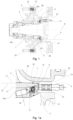
- FIGs 1 and 1a whereby the Figure 1a an enlarged partial representation of the objects according to Fig.1 in the area of the hub neck 3 of the wheel hub 2, show a section through a wheel hub arrangement in the assembled state, with a wheel hub 2 arranged rotatably on an axle element 1 via a hub bearing.
- Two such axle elements 1 are preferably located at the ends of an elongated axle body extending from one side of the vehicle to the other, e.g. the axle body of a commercial vehicle.
- axle element 1 is designed as an axle element that tapers towards the outside of the vehicle, on which bearing seats for an inner roller bearing 20a and an outer roller bearing 20b of a roller bearing are formed.
- the wheel hub 2 and thus the respective vehicle wheel are rotatably mounted on the roller bearing arranged in the interior of the hub.
- a brake disc 22 can be attached to an outer flange 21 of the wheel hub 2 on one side and the vehicle wheel (not shown) on the opposite side by means of wheel bolts 23.
- wheel bolts 23 there are fastenings with holes in the flange 21 of the wheel hub 2 for inserting the wheel bolts 23 through.
- Such a wheel fastening and bearing is particularly suitable for non-driven vehicle axles, e.g. running axles of truck trailers.
- the axle element 1 has a step inwards of the inner roller bearing 20a.
- the inner ring of the roller bearing 20a is supported against the step with a ring 24 axially interposed.
- the ring 24 is designed to be stationary because of its support against the axle element.
- the outer edge of the ring 24 has a small radial distance from the inner circumference 4 of the wheel hub 2.
- a circumferential groove is formed on the inner circumference 4 of the wheel hub 2, into which a locking ring 25 is inserted. This forms a radial projection in comparison to the inner circumference 4 of the wheel hub 2, with the help of which the hub 2 including the hub bearing can be pulled outwards as a unit from the axle element 1.
- the rolling bearing 20a, 20b is sealed by a seal 26 arranged as an extension of the rolling bearing 20a.
- the seal 26 comprises the already mentioned rigid ring 24 and also a two-part arrangement consisting of an inner ring and an outer ring.
- the inner ring and outer ring are arranged in relation to one another in such a way that a nesting is achieved in the axial direction.
- a special feature of this hub bearing is that it can be pulled out of the axle element 1 together with the wheel hub 2 and the roller bearing 20a, 20b. The basic principle for this is described in the EP 0 407 719 B1 described.
- the seal 26 of the hub bearing is gripped by the locking ring 25, which is fixed to the inside of the wheel hub 2 and serves as a radial projection. This is possible because the outer diameter of the seal 26 is larger than the inner diameter of the locking ring 25.
- an ABS sensor which operates inductively, for example, is attached to the axle element 1.
- the ABS sensor 6 sits relatively tightly in a mounting sleeve 27 surrounding the sensor, which in turn is rigidly attached to or in the axle element 1.
- a pole ring 8 is mounted on the wheel hub 1 directly opposite the ABS sensor 6 and at a very short distance from it. This means that it rotates with the wheel hub 1 and is part of the sensor arrangement and the wheel hub arrangement.
- the pole ring 8 is, for example, a stamped and bent part made of sheet metal.
- the wheel hub 2 For mounting the pole ring 8, the wheel hub 2 has a hub neck 3 on the inside of the vehicle with a radius that is reduced compared to the wheel-side wheel hub part.
- the Figure 1a shows more precisely that the hub neck 3 defines with its inner circumference 4 an opening 5 for the central passage of the axle element 1, wherein the outer circumference 11 of the hub neck 3 serves as a pole ring seat 12 for receiving a fastening section 7 of the pole ring 8 is formed.
- the pole ring 8 is pressed onto the pole ring seat 12 by axial sliding and is held there exclusively by friction.
- a pulse generator section 10 which is formed in one piece with the fastening section 7 and extends radially from the fastening section 7 to the wheel hub axis A.
- the pulse generator section 10 On its radially inner edge, the pulse generator section 10 is provided with a flange 18 which leads to a reinforcement of the pole ring 8 against bending loads, which is advantageous for the assembly and disassembly process of the wheel hub arrangement.
- the pole ring 8 is axially supported exclusively on an end face 17 of the hub neck 3, which is formed between the inner circumference 4 and the pole ring seat 12, preferably machined. This leads to a very precise axial runout of the pole ring 8, and thus to an exact sensor signal. In addition, this location of the axial support leads to an improved strength of the pole ring 8, since it can better absorb or withstand bending loads during the assembly and disassembly process.
- the hub neck 3 is of such a length that it accommodates at least parts of the multi-part hub bearing on the inside, namely the seal 26, the ring 24 and possibly the inner roller bearing 20a.
- the pole ring 8 is not attached to the inner circumference 4 of the hub neck 3, where the hub bearing and the locking ring 25 are already arranged and take up space. Instead, the pole ring 8 is attached to the outer circumference 11 of the hub neck 3. In this case, viewed in the longitudinal direction of the hub, the attachment section 7 extends over the seal 26 of the hub bearing.
- the hub neck 3 is provided on its outer circumference 11 with a tool engagement area 13 that runs around the hub neck 3 and is lowered relative to the pole ring seat 12 towards the wheel hub axis A.
- the tool engagement area 13 is designed in the area of the pole ring seat 12 as a step at the vehicle-side end of the hub neck 3. In other words, the outer radius of the hub neck 3 is reduced by a certain value from the pole ring seat 12 to the tool engagement area 13.
- the tool engagement region 13 can also be designed as a circumferential groove in the axial region of the pole ring seat 12, in which case only an oblique chamfer is formed on the vehicle-side front side.
- the pole ring seat 12 and the tool engagement area 13 are machined and provided with a rust protection layer, since both areas are exposed to environmental influences, especially moisture.
- the pulse generator section 10 is provided with openings, preferably slots 19, 19L, evenly distributed in the circumferential direction. Some of the openings or slots 19, 19L have at least one extension RL towards the outside, which reaches at least to the radius of the inner circumference 4 of the hub neck 3.
- the extension R is the extension necessary for sensing by the ABS sensor, while the extension RL towards the outside is between 2 and 10 mm larger than the extension R.
- the longer openings or slots 19L have such a radial extension RL outwards that they reach up to the largest radius of the tool engagement area 13 formed on the front side or up to the front-side bevel (not shown). Dirty water and smaller dirt particles collected inside the hub can therefore always escape again through the outwardly extended sections of the openings or slots 19L, which is promoted by the centrifugal forces during driving.
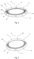
- Both embodiments have recesses 14 in the form of radial slots on their fastening sections 7, which are distributed over the circumference of the fastening section 7 and have non-uniform axial distances from the pulse generator section 10.
- Six recesses 14 are formed on the pole ring 8, whereby the number of these can be higher or lower depending on the application. Furthermore, the radial distances between the recesses 14 are identical.
- the recesses 14 are each formed in pairs, whereby a recess 14 has a respective recess 14 opposite it in relation to the pole ring axis A.
- the pairs of recesses have non-uniform axial distances from one another to the pulse generator section 10.
- One pair is formed at the lower edge of the fastening section 7 towards the flange 21, a second pair opposite at the upper edge towards the pulse generator section 10, and a third pair in between.
- the recesses 14 of the second embodiment according to Figure 3 show one of Figure 2 different distribution of the recesses 14.
- all recesses 14 are distributed over the outer circumferential surface of the fastening section 7, each with its own axial distance.
- the recesses 14 are arranged in relation to one another in such a way that the adjacent recesses 14 have the smallest axial distance from the central recess 14. Consequently, one can speak of a spiral shape in which the recesses 14 are arranged on the fastening section 7.
- Figure 4 discloses a schematic side view of the wheel hub 2 with the pole ring 8 pressed onto it, to illustrate the interaction of axially offset recesses 14 and the tool engagement area 13 formed on the front end of the hub neck 3.
- Three recesses 14, 14a can be seen, each with a different axial position on the fastening section 7, whereby only the recess 14a axially closest to the pulse generator section 10 at least partially radially covers the tool engagement area 13.
- the overlap in the axial direction is so large that the tool engagement area 13, which is still accessible, offers enough space to accommodate the end of a lever tool 28.
- Figure 5 shows a schematic sectional view of the wheel hub 2 with the pole ring 8 pressed on and a locked lever tool 28, for a better representation of the lever mechanism.
- the lever tool 28 is guided with its end into the recess 14a and at the same time comes to rest on the tool engagement area 13 and on a front-side contact 32 of the tool engagement area 13. If the lever tool 28 is now pulled, whereby it rests on the contact 32 and pivots around this area, the lever tool 28 also comes to rest on the wall 31 of the recess 14a on the vehicle side with its lever arm 29.
- the wall 31 is the longitudinal edge of the recess 14, 14a closest to the pulse generator section 10. If the lever movement of the lever arm 29 is continued, a force is exerted on the pole ring 8 in the axial direction, which force of the frictional engagement between the pole ring 8 and the pole ring seat 12, so that the pole ring shifts slightly.
- a second recess 14 has already formed, according to Figure 4 , optimally positioned to the tool engagement area 13 in order to repeat the previously mentioned step.
- the recesses 14, 14a are therefore selected in their position and number such that at the latest when the above-mentioned process is carried out at the last recess 14, which is also the one closest to the lower edge of the fastening area 7, the pole ring 8 slides completely down from the pole ring seat 12.
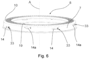
- Figure 6 shows a further, third embodiment of the pole ring 8, which is partially derived from the pole ring of the first embodiment.
- both the recesses 14a and the further recesses 14 are formed in pairs in the fastening section 7, with one recess of the pair being exactly opposite the other recess of the pair in relation to the pole ring axis A.
- two lever tools 28 are preferably attached and actuated synchronously, which prevents any tilting of the pole ring when it is stripped from the wheel hub 2.
- each recess pair has the same axial distance from the pulse generator section 10.
- At least one and preferably two recess pairs, which are composed of recesses 14a, are arranged at the upper edge of the fastening section 7 close to the pulse generator section 10.
- Another recess pair is close to the other, lower edge of the fastening section 7, and yet another recess pair is arranged in an axial position between the aforementioned recess pairs.
- the recesses 14a of the recess pair and preferably of the two recess pairs that are formed close to the upper edge and thus close to the pulse generator section 10 have the smallest axial distance to the pulse generator section 10 compared to all other recesses 14.
- the four recesses 14a of the two pairs of recesses with the smallest axial distance to the pulse generator section are arranged at 90 ° angular intervals to each other around the pole ring axis A.
- the four recesses 14a distributed over two pairs are located at circumferential positions which are, for example, 0°, 90°, 180° and 270°.
- the first further pair of recesses is then located at circumferential positions of 45° and 225° and the yet further pair of recesses is located at circumferential positions of 135° and 315°.
- the recesses 14a of the one or two pairs of recesses with the smallest axial distance to the pulse generator section 10 can have a different shape or contour compared to all other recesses 14.
- the contour extends Fig.6 with its side facing away from the pulse generator area 10, wedge-shaped or otherwise tapering towards the other edge of the fastening section 7, and thus allows a better view of the tool engagement area 13 arranged underneath due to the larger opening area.
- the respective different shape or contour already signals to the operator that these are the recesses 14a to which the two lever tools 28 must be applied first.
- the four recesses 14a of the two pairs of recesses with the smallest axial distance to the pulse generator section 10 have markings 33 that are different from any markings 33 on the other recesses 14 of the other pairs of recesses with a greater axial distance to the pulse generator section 10.
- the markings 33 according to Figure 6 , to the Roman numerals "I” to "III", which identify the adjacent recesses 14, 14a, corresponding to the sequence of insertion of the lever tools 28 into the recesses 14, 14a.
Landscapes
- Engineering & Computer Science (AREA)
- Mechanical Engineering (AREA)
- Transportation (AREA)
- Regulating Braking Force (AREA)
- Rolling Contact Bearings (AREA)
Applications Claiming Priority (3)
| Application Number | Priority Date | Filing Date | Title |
|---|---|---|---|
| DE102020114052.5A DE102020114052A1 (de) | 2020-05-26 | 2020-05-26 | Radnabenanordnung für ein Fahrzeugrad sowie Polring eines ABS-Sensors |
| DE102020130414.5A DE102020130414A1 (de) | 2020-11-18 | 2020-11-18 | Radnabenanordnung für ein Fahrzeugrad sowie Polring eines ABS-Sensors |
| PCT/DE2021/100427 WO2021239181A1 (de) | 2020-05-26 | 2021-05-10 | Radnabenanordnung für ein fahrzeugrad sowie polring eines abs-sensors |
Publications (2)
| Publication Number | Publication Date |
|---|---|
| EP4157682A1 EP4157682A1 (de) | 2023-04-05 |
| EP4157682B1 true EP4157682B1 (de) | 2024-06-19 |
Family
ID=76076183
Family Applications (1)
| Application Number | Title | Priority Date | Filing Date |
|---|---|---|---|
| EP21727358.0A Active EP4157682B1 (de) | 2020-05-26 | 2021-05-10 | Radnabenanordnung für ein fahrzeugrad sowie polring eines abs-sensors |
Country Status (6)
| Country | Link |
|---|---|
| EP (1) | EP4157682B1 (pl) |
| CN (1) | CN115515831A (pl) |
| AU (1) | AU2021280128B2 (pl) |
| ES (1) | ES2983782T3 (pl) |
| PL (1) | PL4157682T3 (pl) |
| WO (1) | WO2021239181A1 (pl) |
Family Cites Families (9)
| Publication number | Priority date | Publication date | Assignee | Title |
|---|---|---|---|---|
| DE3922858A1 (de) | 1989-07-12 | 1991-01-17 | Bergische Achsen Kotz Soehne | Radlager fuer anhaengerachsen |
| JP2000161394A (ja) * | 1998-11-24 | 2000-06-13 | Dana Corp | 選択的に係合可能な、かつ係合離脱可能なユニット及びその騒音を低減するハブ |
| DE10237504B4 (de) * | 2002-08-16 | 2006-11-09 | Knorr-Bremse Systeme für Nutzfahrzeuge GmbH | Vorrichtung zur Impulserzeugung an einem Fahrzeugrad und Verfahren zur Montage der Vorrichtung |
| EP1826889B1 (de) * | 2006-02-24 | 2015-09-30 | ThyssenKrupp Aufzugswerke GmbH | Verfahren und Vorrichtung zum Anbringen von Magneten |
| US9261145B2 (en) * | 2008-04-10 | 2016-02-16 | Ntn Corporation | Bearing device for a wheel |
| DE102011084261B4 (de) | 2011-10-11 | 2015-11-19 | Schaeffler Technologies AG & Co. KG | Aktiver Ringsensor mit Passstiften am Lager fixiert |
| DE102014106519A1 (de) | 2014-05-09 | 2015-11-12 | Bpw Bergische Achsen Kg | Radnabenanordnung für ein Fahrzeugrad sowie Polring eines ABS-Sensors |
| DE102017112075A1 (de) * | 2017-06-01 | 2018-12-06 | Knorr-Bremse Systeme für Nutzfahrzeuge GmbH | An einem drehbaren Bauteil eines Kraftfahrzeuges verdrehsicher gehaltenes Polrad |
| US10118630B1 (en) * | 2017-07-26 | 2018-11-06 | Strato, Inc. | Truck-mounted brake system |
-
2021
- 2021-05-10 PL PL21727358.0T patent/PL4157682T3/pl unknown
- 2021-05-10 AU AU2021280128A patent/AU2021280128B2/en active Active
- 2021-05-10 CN CN202180033814.3A patent/CN115515831A/zh active Pending
- 2021-05-10 WO PCT/DE2021/100427 patent/WO2021239181A1/de not_active Ceased
- 2021-05-10 EP EP21727358.0A patent/EP4157682B1/de active Active
- 2021-05-10 ES ES21727358T patent/ES2983782T3/es active Active
Also Published As
| Publication number | Publication date |
|---|---|
| EP4157682A1 (de) | 2023-04-05 |
| PL4157682T3 (pl) | 2024-10-28 |
| AU2021280128B2 (en) | 2026-05-14 |
| CN115515831A (zh) | 2022-12-23 |
| WO2021239181A1 (de) | 2021-12-02 |
| AU2021280128A1 (en) | 2024-01-04 |
| ES2983782T3 (es) | 2024-10-24 |
Similar Documents
| Publication | Publication Date | Title |
|---|---|---|
| EP4299338B1 (de) | Radnabenanordnung für ein fahrzeugrad sowie polring eines abs-sensors | |
| EP0417417B1 (de) | Zwillingsrolle, insbesondere Lenkrolle | |
| DE3222711C2 (de) | Ausrücklager | |
| DE2929477A1 (de) | Radkappe fuer kraftfahrzeuge | |
| DE112009002345T5 (de) | Verarbeitung von Videodaten in Geräten mit eingeschränkten Ressourcen | |
| DE602004010630T2 (de) | Verfahren zur montage einer wälzlagervorrichtung | |
| EP3612747B1 (de) | Scheibenbremse, bremssattel einer scheibenbremse sowie niederhalter und blattfeder zur befestigung der bremsbeläge einer scheibenbremse | |
| WO2018134384A1 (de) | Radnabe, system aus radnabe und bremsscheibe | |
| DE2906734C3 (de) | Laufrolle in Zwillingsradanordnung | |
| EP2934984B1 (de) | Lenksäule für ein kraftfahrzeug | |
| EP1456544B1 (de) | Kugelgelenk | |
| EP1859971B1 (de) | Vorrichtung zum Blockieren eines Federbeins eines Kraftfahrzeugs | |
| EP3061916A1 (de) | Radscheibenanordnung eines Rotors und Verfahren zur Montage einer Radscheibenanordnung eines Rotors | |
| DE19830890B4 (de) | Dreiringnadellagerung für einen Pumpenteil | |
| EP3023656A1 (de) | Wälzlager und verfahren zum bestücken eines käfigs eines wälzlagers mit wälzkörpern | |
| EP0475088B1 (de) | Radlager für Anhängerachsen | |
| EP3199827B1 (de) | Scheibenbremse sowie niederhalter für die befestigung von bremsbelägen in einer scheibenbremse | |
| DE2711561B2 (de) | Kraftfahrzeugrad mit einer selbsttätigen Auswuchtvorrichtung | |
| EP1694518A1 (de) | Radlagermodul in einem radträger | |
| EP2814633A1 (de) | Verfahren zur montage eines ringlagers in ein lenkgehäuse | |
| DE102020130414A1 (de) | Radnabenanordnung für ein Fahrzeugrad sowie Polring eines ABS-Sensors | |
| EP4157682A1 (de) | Radnabenanordnung für ein fahrzeugrad sowie polring eines abs-sensors | |
| DE102020113706B3 (de) | Montagehilfe und Verfahren zur Montage und Demontage von Blockierelementen an einem Federbein | |
| DE102020114052A1 (de) | Radnabenanordnung für ein Fahrzeugrad sowie Polring eines ABS-Sensors | |
| DE3141877C2 (de) | Fahrzeugrad |
Legal Events
| Date | Code | Title | Description |
|---|---|---|---|
| STAA | Information on the status of an ep patent application or granted ep patent |
Free format text: STATUS: UNKNOWN |
|
| STAA | Information on the status of an ep patent application or granted ep patent |
Free format text: STATUS: THE INTERNATIONAL PUBLICATION HAS BEEN MADE |
|
| PUAI | Public reference made under article 153(3) epc to a published international application that has entered the european phase |
Free format text: ORIGINAL CODE: 0009012 |
|
| STAA | Information on the status of an ep patent application or granted ep patent |
Free format text: STATUS: REQUEST FOR EXAMINATION WAS MADE |
|
| 17P | Request for examination filed |
Effective date: 20221110 |
|
| AK | Designated contracting states |
Kind code of ref document: A1 Designated state(s): AL AT BE BG CH CY CZ DE DK EE ES FI FR GB GR HR HU IE IS IT LI LT LU LV MC MK MT NL NO PL PT RO RS SE SI SK SM TR |
|
| DAV | Request for validation of the european patent (deleted) | ||
| DAX | Request for extension of the european patent (deleted) | ||
| REG | Reference to a national code |
Ref country code: DE Ref legal event code: R079 Free format text: PREVIOUS MAIN CLASS: B60T0008320000 Ipc: B60B0027000000 Ref country code: DE Ref legal event code: R079 Ref document number: 502021004049 Country of ref document: DE Free format text: PREVIOUS MAIN CLASS: B60T0008320000 Ipc: B60B0027000000 |
|
| RIC1 | Information provided on ipc code assigned before grant |
Ipc: B60T 8/32 20060101ALI20240111BHEP Ipc: G01P 3/44 20060101ALI20240111BHEP Ipc: B60B 27/00 20060101AFI20240111BHEP |
|
| GRAP | Despatch of communication of intention to grant a patent |
Free format text: ORIGINAL CODE: EPIDOSNIGR1 |
|
| STAA | Information on the status of an ep patent application or granted ep patent |
Free format text: STATUS: GRANT OF PATENT IS INTENDED |
|
| INTG | Intention to grant announced |
Effective date: 20240226 |
|
| GRAS | Grant fee paid |
Free format text: ORIGINAL CODE: EPIDOSNIGR3 |
|
| GRAA | (expected) grant |
Free format text: ORIGINAL CODE: 0009210 |
|
| STAA | Information on the status of an ep patent application or granted ep patent |
Free format text: STATUS: THE PATENT HAS BEEN GRANTED |
|
| P01 | Opt-out of the competence of the unified patent court (upc) registered |
Effective date: 20240418 |
|
| AK | Designated contracting states |
Kind code of ref document: B1 Designated state(s): AL AT BE BG CH CY CZ DE DK EE ES FI FR GB GR HR HU IE IS IT LI LT LU LV MC MK MT NL NO PL PT RO RS SE SI SK SM TR |
|
| REG | Reference to a national code |
Ref country code: GB Ref legal event code: FG4D Free format text: NOT ENGLISH |
|
| REG | Reference to a national code |
Ref country code: CH Ref legal event code: EP |
|
| REG | Reference to a national code |
Ref country code: DE Ref legal event code: R096 Ref document number: 502021004049 Country of ref document: DE |
|
| REG | Reference to a national code |
Ref country code: SE Ref legal event code: TRGR |
|
| REG | Reference to a national code |
Ref country code: NL Ref legal event code: FP |
|
| PG25 | Lapsed in a contracting state [announced via postgrant information from national office to epo] |
Ref country code: BG Free format text: LAPSE BECAUSE OF FAILURE TO SUBMIT A TRANSLATION OF THE DESCRIPTION OR TO PAY THE FEE WITHIN THE PRESCRIBED TIME-LIMIT Effective date: 20240619 |
|
| PG25 | Lapsed in a contracting state [announced via postgrant information from national office to epo] |
Ref country code: HR Free format text: LAPSE BECAUSE OF FAILURE TO SUBMIT A TRANSLATION OF THE DESCRIPTION OR TO PAY THE FEE WITHIN THE PRESCRIBED TIME-LIMIT Effective date: 20240619 Ref country code: FI Free format text: LAPSE BECAUSE OF FAILURE TO SUBMIT A TRANSLATION OF THE DESCRIPTION OR TO PAY THE FEE WITHIN THE PRESCRIBED TIME-LIMIT Effective date: 20240619 |
|
| REG | Reference to a national code |
Ref country code: LT Ref legal event code: MG9D |
|
| PG25 | Lapsed in a contracting state [announced via postgrant information from national office to epo] |
Ref country code: GR Free format text: LAPSE BECAUSE OF FAILURE TO SUBMIT A TRANSLATION OF THE DESCRIPTION OR TO PAY THE FEE WITHIN THE PRESCRIBED TIME-LIMIT Effective date: 20240920 |
|
| REG | Reference to a national code |
Ref country code: ES Ref legal event code: FG2A Ref document number: 2983782 Country of ref document: ES Kind code of ref document: T3 Effective date: 20241024 |
|
| PG25 | Lapsed in a contracting state [announced via postgrant information from national office to epo] |
Ref country code: LV Free format text: LAPSE BECAUSE OF FAILURE TO SUBMIT A TRANSLATION OF THE DESCRIPTION OR TO PAY THE FEE WITHIN THE PRESCRIBED TIME-LIMIT Effective date: 20240619 |
|
| PG25 | Lapsed in a contracting state [announced via postgrant information from national office to epo] |
Ref country code: NO Free format text: LAPSE BECAUSE OF FAILURE TO SUBMIT A TRANSLATION OF THE DESCRIPTION OR TO PAY THE FEE WITHIN THE PRESCRIBED TIME-LIMIT Effective date: 20240919 Ref country code: LV Free format text: LAPSE BECAUSE OF FAILURE TO SUBMIT A TRANSLATION OF THE DESCRIPTION OR TO PAY THE FEE WITHIN THE PRESCRIBED TIME-LIMIT Effective date: 20240619 Ref country code: HR Free format text: LAPSE BECAUSE OF FAILURE TO SUBMIT A TRANSLATION OF THE DESCRIPTION OR TO PAY THE FEE WITHIN THE PRESCRIBED TIME-LIMIT Effective date: 20240619 Ref country code: GR Free format text: LAPSE BECAUSE OF FAILURE TO SUBMIT A TRANSLATION OF THE DESCRIPTION OR TO PAY THE FEE WITHIN THE PRESCRIBED TIME-LIMIT Effective date: 20240920 Ref country code: FI Free format text: LAPSE BECAUSE OF FAILURE TO SUBMIT A TRANSLATION OF THE DESCRIPTION OR TO PAY THE FEE WITHIN THE PRESCRIBED TIME-LIMIT Effective date: 20240619 Ref country code: BG Free format text: LAPSE BECAUSE OF FAILURE TO SUBMIT A TRANSLATION OF THE DESCRIPTION OR TO PAY THE FEE WITHIN THE PRESCRIBED TIME-LIMIT Effective date: 20240619 Ref country code: RS Free format text: LAPSE BECAUSE OF FAILURE TO SUBMIT A TRANSLATION OF THE DESCRIPTION OR TO PAY THE FEE WITHIN THE PRESCRIBED TIME-LIMIT Effective date: 20240919 |
|
| PG25 | Lapsed in a contracting state [announced via postgrant information from national office to epo] |
Ref country code: PT Free format text: LAPSE BECAUSE OF FAILURE TO SUBMIT A TRANSLATION OF THE DESCRIPTION OR TO PAY THE FEE WITHIN THE PRESCRIBED TIME-LIMIT Effective date: 20241021 |
|
| PG25 | Lapsed in a contracting state [announced via postgrant information from national office to epo] |
Ref country code: PT Free format text: LAPSE BECAUSE OF FAILURE TO SUBMIT A TRANSLATION OF THE DESCRIPTION OR TO PAY THE FEE WITHIN THE PRESCRIBED TIME-LIMIT Effective date: 20241021 |
|
| PG25 | Lapsed in a contracting state [announced via postgrant information from national office to epo] |
Ref country code: EE Free format text: LAPSE BECAUSE OF FAILURE TO SUBMIT A TRANSLATION OF THE DESCRIPTION OR TO PAY THE FEE WITHIN THE PRESCRIBED TIME-LIMIT Effective date: 20240619 |
|
| PG25 | Lapsed in a contracting state [announced via postgrant information from national office to epo] |
Ref country code: IS Free format text: LAPSE BECAUSE OF FAILURE TO SUBMIT A TRANSLATION OF THE DESCRIPTION OR TO PAY THE FEE WITHIN THE PRESCRIBED TIME-LIMIT Effective date: 20241019 |
|
| PG25 | Lapsed in a contracting state [announced via postgrant information from national office to epo] |
Ref country code: CZ Free format text: LAPSE BECAUSE OF FAILURE TO SUBMIT A TRANSLATION OF THE DESCRIPTION OR TO PAY THE FEE WITHIN THE PRESCRIBED TIME-LIMIT Effective date: 20240619 |
|
| PG25 | Lapsed in a contracting state [announced via postgrant information from national office to epo] |
Ref country code: RO Free format text: LAPSE BECAUSE OF FAILURE TO SUBMIT A TRANSLATION OF THE DESCRIPTION OR TO PAY THE FEE WITHIN THE PRESCRIBED TIME-LIMIT Effective date: 20240619 Ref country code: SK Free format text: LAPSE BECAUSE OF FAILURE TO SUBMIT A TRANSLATION OF THE DESCRIPTION OR TO PAY THE FEE WITHIN THE PRESCRIBED TIME-LIMIT Effective date: 20240619 |
|
| PG25 | Lapsed in a contracting state [announced via postgrant information from national office to epo] |
Ref country code: SM Free format text: LAPSE BECAUSE OF FAILURE TO SUBMIT A TRANSLATION OF THE DESCRIPTION OR TO PAY THE FEE WITHIN THE PRESCRIBED TIME-LIMIT Effective date: 20240619 |
|
| PG25 | Lapsed in a contracting state [announced via postgrant information from national office to epo] |
Ref country code: SM Free format text: LAPSE BECAUSE OF FAILURE TO SUBMIT A TRANSLATION OF THE DESCRIPTION OR TO PAY THE FEE WITHIN THE PRESCRIBED TIME-LIMIT Effective date: 20240619 Ref country code: SK Free format text: LAPSE BECAUSE OF FAILURE TO SUBMIT A TRANSLATION OF THE DESCRIPTION OR TO PAY THE FEE WITHIN THE PRESCRIBED TIME-LIMIT Effective date: 20240619 Ref country code: RO Free format text: LAPSE BECAUSE OF FAILURE TO SUBMIT A TRANSLATION OF THE DESCRIPTION OR TO PAY THE FEE WITHIN THE PRESCRIBED TIME-LIMIT Effective date: 20240619 Ref country code: IS Free format text: LAPSE BECAUSE OF FAILURE TO SUBMIT A TRANSLATION OF THE DESCRIPTION OR TO PAY THE FEE WITHIN THE PRESCRIBED TIME-LIMIT Effective date: 20241019 Ref country code: EE Free format text: LAPSE BECAUSE OF FAILURE TO SUBMIT A TRANSLATION OF THE DESCRIPTION OR TO PAY THE FEE WITHIN THE PRESCRIBED TIME-LIMIT Effective date: 20240619 Ref country code: CZ Free format text: LAPSE BECAUSE OF FAILURE TO SUBMIT A TRANSLATION OF THE DESCRIPTION OR TO PAY THE FEE WITHIN THE PRESCRIBED TIME-LIMIT Effective date: 20240619 |
|
| REG | Reference to a national code |
Ref country code: DE Ref legal event code: R097 Ref document number: 502021004049 Country of ref document: DE |
|
| PG25 | Lapsed in a contracting state [announced via postgrant information from national office to epo] |
Ref country code: DK Free format text: LAPSE BECAUSE OF FAILURE TO SUBMIT A TRANSLATION OF THE DESCRIPTION OR TO PAY THE FEE WITHIN THE PRESCRIBED TIME-LIMIT Effective date: 20240619 |
|
| PLBE | No opposition filed within time limit |
Free format text: ORIGINAL CODE: 0009261 |
|
| STAA | Information on the status of an ep patent application or granted ep patent |
Free format text: STATUS: NO OPPOSITION FILED WITHIN TIME LIMIT |
|
| 26N | No opposition filed |
Effective date: 20250320 |
|
| PGFP | Annual fee paid to national office [announced via postgrant information from national office to epo] |
Ref country code: NL Payment date: 20250522 Year of fee payment: 5 |
|
| PGFP | Annual fee paid to national office [announced via postgrant information from national office to epo] |
Ref country code: ES Payment date: 20250616 Year of fee payment: 5 |
|
| PGFP | Annual fee paid to national office [announced via postgrant information from national office to epo] |
Ref country code: IT Payment date: 20250530 Year of fee payment: 5 |
|
| PGFP | Annual fee paid to national office [announced via postgrant information from national office to epo] |
Ref country code: FR Payment date: 20250521 Year of fee payment: 5 |
|
| PGFP | Annual fee paid to national office [announced via postgrant information from national office to epo] |
Ref country code: AT Payment date: 20250721 Year of fee payment: 5 |
|
| PGFP | Annual fee paid to national office [announced via postgrant information from national office to epo] |
Ref country code: SE Payment date: 20250522 Year of fee payment: 5 |
|
| PGFP | Annual fee paid to national office [announced via postgrant information from national office to epo] |
Ref country code: DE Payment date: 20250721 Year of fee payment: 5 |
|
| REG | Reference to a national code |
Ref country code: CH Ref legal event code: H13 Free format text: ST27 STATUS EVENT CODE: U-0-0-H10-H13 (AS PROVIDED BY THE NATIONAL OFFICE) Effective date: 20251223 |
|
| PG25 | Lapsed in a contracting state [announced via postgrant information from national office to epo] |
Ref country code: LU Free format text: LAPSE BECAUSE OF NON-PAYMENT OF DUE FEES Effective date: 20250510 |
|
| PG25 | Lapsed in a contracting state [announced via postgrant information from national office to epo] |
Ref country code: CH Free format text: LAPSE BECAUSE OF NON-PAYMENT OF DUE FEES Effective date: 20250531 |
|
| REG | Reference to a national code |
Ref country code: BE Ref legal event code: MM Effective date: 20250531 |
|
| PG25 | Lapsed in a contracting state [announced via postgrant information from national office to epo] |
Ref country code: MC Free format text: LAPSE BECAUSE OF FAILURE TO SUBMIT A TRANSLATION OF THE DESCRIPTION OR TO PAY THE FEE WITHIN THE PRESCRIBED TIME-LIMIT Effective date: 20240619 |
|
| PGFP | Annual fee paid to national office [announced via postgrant information from national office to epo] |
Ref country code: GB Payment date: 20260324 Year of fee payment: 6 |
|
| PG25 | Lapsed in a contracting state [announced via postgrant information from national office to epo] |
Ref country code: IE Free format text: LAPSE BECAUSE OF NON-PAYMENT OF DUE FEES Effective date: 20250510 |
|
| PG25 | Lapsed in a contracting state [announced via postgrant information from national office to epo] |
Ref country code: BE Free format text: LAPSE BECAUSE OF NON-PAYMENT OF DUE FEES Effective date: 20250531 |
|
| PGFP | Annual fee paid to national office [announced via postgrant information from national office to epo] |
Ref country code: PL Payment date: 20260320 Year of fee payment: 6 |