EP4155748A1 - Dispositif et procédé de gestion de batteries - Google Patents
Dispositif et procédé de gestion de batteries Download PDFInfo
- Publication number
- EP4155748A1 EP4155748A1 EP21867129.5A EP21867129A EP4155748A1 EP 4155748 A1 EP4155748 A1 EP 4155748A1 EP 21867129 A EP21867129 A EP 21867129A EP 4155748 A1 EP4155748 A1 EP 4155748A1
- Authority
- EP
- European Patent Office
- Prior art keywords
- voltage
- differential
- battery
- profile
- battery cell
- Prior art date
- Legal status (The legal status is an assumption and is not a legal conclusion. Google has not performed a legal analysis and makes no representation as to the accuracy of the status listed.)
- Granted
Links
- 238000000034 method Methods 0.000 title abstract description 10
- 230000008859 change Effects 0.000 claims abstract description 98
- 230000015556 catabolic process Effects 0.000 claims abstract description 60
- 238000006731 degradation reaction Methods 0.000 claims abstract description 60
- 238000007726 management method Methods 0.000 claims description 53
- 230000001133 acceleration Effects 0.000 claims description 22
- 230000008901 benefit Effects 0.000 abstract description 11
- 238000010586 diagram Methods 0.000 description 15
- 230000003247 decreasing effect Effects 0.000 description 8
- 230000006870 function Effects 0.000 description 6
- PXHVJJICTQNCMI-UHFFFAOYSA-N Nickel Chemical compound [Ni] PXHVJJICTQNCMI-UHFFFAOYSA-N 0.000 description 4
- 238000007599 discharging Methods 0.000 description 4
- 238000012986 modification Methods 0.000 description 4
- 230000004048 modification Effects 0.000 description 4
- 230000008569 process Effects 0.000 description 4
- WHXSMMKQMYFTQS-UHFFFAOYSA-N Lithium Chemical compound [Li] WHXSMMKQMYFTQS-UHFFFAOYSA-N 0.000 description 3
- 230000005856 abnormality Effects 0.000 description 3
- 238000004891 communication Methods 0.000 description 3
- 230000000694 effects Effects 0.000 description 3
- 229910052744 lithium Inorganic materials 0.000 description 3
- 229910052759 nickel Inorganic materials 0.000 description 2
- UFHFLCQGNIYNRP-UHFFFAOYSA-N Hydrogen Chemical compound [H][H] UFHFLCQGNIYNRP-UHFFFAOYSA-N 0.000 description 1
- OJIJEKBXJYRIBZ-UHFFFAOYSA-N cadmium nickel Chemical compound [Ni].[Cd] OJIJEKBXJYRIBZ-UHFFFAOYSA-N 0.000 description 1
- 238000006243 chemical reaction Methods 0.000 description 1
- 230000007547 defect Effects 0.000 description 1
- 238000004146 energy storage Methods 0.000 description 1
- 230000036541 health Effects 0.000 description 1
- 229910052739 hydrogen Inorganic materials 0.000 description 1
- 239000001257 hydrogen Substances 0.000 description 1
- 238000007689 inspection Methods 0.000 description 1
- 238000013507 mapping Methods 0.000 description 1
- 230000003446 memory effect Effects 0.000 description 1
- QELJHCBNGDEXLD-UHFFFAOYSA-N nickel zinc Chemical compound [Ni].[Zn] QELJHCBNGDEXLD-UHFFFAOYSA-N 0.000 description 1
- 230000001151 other effect Effects 0.000 description 1
- 229920000642 polymer Polymers 0.000 description 1
- 238000012545 processing Methods 0.000 description 1
- 238000006467 substitution reaction Methods 0.000 description 1
- 230000001502 supplementing effect Effects 0.000 description 1
Images


Classifications
-
- G—PHYSICS
- G01—MEASURING; TESTING
- G01R—MEASURING ELECTRIC VARIABLES; MEASURING MAGNETIC VARIABLES
- G01R31/00—Arrangements for testing electric properties; Arrangements for locating electric faults; Arrangements for electrical testing characterised by what is being tested not provided for elsewhere
- G01R31/36—Arrangements for testing, measuring or monitoring the electrical condition of accumulators or electric batteries, e.g. capacity or state of charge [SoC]
- G01R31/392—Determining battery ageing or deterioration, e.g. state of health
-
- G—PHYSICS
- G01—MEASURING; TESTING
- G01R—MEASURING ELECTRIC VARIABLES; MEASURING MAGNETIC VARIABLES
- G01R19/00—Arrangements for measuring currents or voltages or for indicating presence or sign thereof
- G01R19/165—Indicating that current or voltage is either above or below a predetermined value or within or outside a predetermined range of values
- G01R19/16566—Circuits and arrangements for comparing voltage or current with one or several thresholds and for indicating the result not covered by subgroups G01R19/16504, G01R19/16528, G01R19/16533
-
- G—PHYSICS
- G01—MEASURING; TESTING
- G01R—MEASURING ELECTRIC VARIABLES; MEASURING MAGNETIC VARIABLES
- G01R19/00—Arrangements for measuring currents or voltages or for indicating presence or sign thereof
- G01R19/30—Measuring the maximum or the minimum value of current or voltage reached in a time interval
-
- G—PHYSICS
- G01—MEASURING; TESTING
- G01R—MEASURING ELECTRIC VARIABLES; MEASURING MAGNETIC VARIABLES
- G01R31/00—Arrangements for testing electric properties; Arrangements for locating electric faults; Arrangements for electrical testing characterised by what is being tested not provided for elsewhere
- G01R31/36—Arrangements for testing, measuring or monitoring the electrical condition of accumulators or electric batteries, e.g. capacity or state of charge [SoC]
- G01R31/3644—Constructional arrangements
- G01R31/3648—Constructional arrangements comprising digital calculation means, e.g. for performing an algorithm
-
- G—PHYSICS
- G01—MEASURING; TESTING
- G01R—MEASURING ELECTRIC VARIABLES; MEASURING MAGNETIC VARIABLES
- G01R31/00—Arrangements for testing electric properties; Arrangements for locating electric faults; Arrangements for electrical testing characterised by what is being tested not provided for elsewhere
- G01R31/36—Arrangements for testing, measuring or monitoring the electrical condition of accumulators or electric batteries, e.g. capacity or state of charge [SoC]
- G01R31/367—Software therefor, e.g. for battery testing using modelling or look-up tables
-
- G—PHYSICS
- G01—MEASURING; TESTING
- G01R—MEASURING ELECTRIC VARIABLES; MEASURING MAGNETIC VARIABLES
- G01R31/00—Arrangements for testing electric properties; Arrangements for locating electric faults; Arrangements for electrical testing characterised by what is being tested not provided for elsewhere
- G01R31/36—Arrangements for testing, measuring or monitoring the electrical condition of accumulators or electric batteries, e.g. capacity or state of charge [SoC]
- G01R31/382—Arrangements for monitoring battery or accumulator variables, e.g. SoC
- G01R31/3835—Arrangements for monitoring battery or accumulator variables, e.g. SoC involving only voltage measurements
-
- H—ELECTRICITY
- H01—ELECTRIC ELEMENTS
- H01M—PROCESSES OR MEANS, e.g. BATTERIES, FOR THE DIRECT CONVERSION OF CHEMICAL ENERGY INTO ELECTRICAL ENERGY
- H01M10/00—Secondary cells; Manufacture thereof
- H01M10/42—Methods or arrangements for servicing or maintenance of secondary cells or secondary half-cells
- H01M10/425—Structural combination with electronic components, e.g. electronic circuits integrated to the outside of the casing
-
- H—ELECTRICITY
- H01—ELECTRIC ELEMENTS
- H01M—PROCESSES OR MEANS, e.g. BATTERIES, FOR THE DIRECT CONVERSION OF CHEMICAL ENERGY INTO ELECTRICAL ENERGY
- H01M10/00—Secondary cells; Manufacture thereof
- H01M10/42—Methods or arrangements for servicing or maintenance of secondary cells or secondary half-cells
- H01M10/44—Methods for charging or discharging
-
- H—ELECTRICITY
- H01—ELECTRIC ELEMENTS
- H01M—PROCESSES OR MEANS, e.g. BATTERIES, FOR THE DIRECT CONVERSION OF CHEMICAL ENERGY INTO ELECTRICAL ENERGY
- H01M10/00—Secondary cells; Manufacture thereof
- H01M10/42—Methods or arrangements for servicing or maintenance of secondary cells or secondary half-cells
- H01M10/48—Accumulators combined with arrangements for measuring, testing or indicating the condition of cells, e.g. the level or density of the electrolyte
-
- H—ELECTRICITY
- H02—GENERATION; CONVERSION OR DISTRIBUTION OF ELECTRIC POWER
- H02J—CIRCUIT ARRANGEMENTS OR SYSTEMS FOR SUPPLYING OR DISTRIBUTING ELECTRIC POWER; SYSTEMS FOR STORING ELECTRIC ENERGY
- H02J7/00—Circuit arrangements for charging or depolarising batteries or for supplying loads from batteries
- H02J7/0047—Circuit arrangements for charging or depolarising batteries or for supplying loads from batteries with monitoring or indicating devices or circuits
-
- H—ELECTRICITY
- H01—ELECTRIC ELEMENTS
- H01M—PROCESSES OR MEANS, e.g. BATTERIES, FOR THE DIRECT CONVERSION OF CHEMICAL ENERGY INTO ELECTRICAL ENERGY
- H01M10/00—Secondary cells; Manufacture thereof
- H01M10/42—Methods or arrangements for servicing or maintenance of secondary cells or secondary half-cells
- H01M10/425—Structural combination with electronic components, e.g. electronic circuits integrated to the outside of the casing
- H01M2010/4271—Battery management systems including electronic circuits, e.g. control of current or voltage to keep battery in healthy state, cell balancing
-
- Y—GENERAL TAGGING OF NEW TECHNOLOGICAL DEVELOPMENTS; GENERAL TAGGING OF CROSS-SECTIONAL TECHNOLOGIES SPANNING OVER SEVERAL SECTIONS OF THE IPC; TECHNICAL SUBJECTS COVERED BY FORMER USPC CROSS-REFERENCE ART COLLECTIONS [XRACs] AND DIGESTS
- Y02—TECHNOLOGIES OR APPLICATIONS FOR MITIGATION OR ADAPTATION AGAINST CLIMATE CHANGE
- Y02E—REDUCTION OF GREENHOUSE GAS [GHG] EMISSIONS, RELATED TO ENERGY GENERATION, TRANSMISSION OR DISTRIBUTION
- Y02E60/00—Enabling technologies; Technologies with a potential or indirect contribution to GHG emissions mitigation
- Y02E60/10—Energy storage using batteries
Definitions
- the present disclosure relates to a battery management apparatus and method, and more particularly, to a battery management apparatus and method for judging whether degradation of a battery cell is accelerated.
- Batteries commercially available at present include nickel-cadmium batteries, nickel hydrogen batteries, nickel-zinc batteries, lithium batteries and the like.
- the lithium batteries are in the limelight since they have almost no memory effect compared to nickel-based batteries and also have very low self-charging rate and high energy density.
- Patent Document 1 an inspection system for comparing a feature point of a previously stored V-dQ/dV curve with a feature point of a dQ/dV actual value is disclosed (Patent Document 1).
- the abnormality of a battery is detected just by judging whether the feature point of the dQ/dV actual value falls within a predetermined voltage (V) range and a predetermined dQ/dV range.
- Patent Document 1 KR 10-2013-0142884 A
- the present disclosure is designed to solve the problems of the related art, and therefore the present disclosure is directed to providing a battery management apparatus and method that may perform appropriate control to increase the lifespan of a battery cell by judging whether degradation of the battery cell is accelerated.
- a battery management apparatus may comprise: a profile generating unit configured to obtain battery information including a voltage and a capacity of a battery cell and generate a battery profile representing a corresponding relationship between the voltage and the capacity based on the obtained battery information; a profile converting unit configured to receive the battery profile from the profile generating unit and convert the received battery profile into a differential profile representing a corresponding relationship between the voltage and a differential capacity for the voltage; and a control unit configured to obtain a plurality of differential profiles for the battery cell converted by the profile converting unit, select a peak included in a preset criterion voltage region from each of the plurality of obtained differential profiles, determine a voltage change pattern for the voltage of the plurality of selected peaks and a differential capacity change pattern for the differential capacity, and judge whether degradation of the battery cell is accelerated according to whether the determined voltage change pattern corresponds to a preset first reference pattern and whether the determined differential capacity change pattern corresponds to a preset second reference pattern.
- the control unit may be configured to determine the voltage change pattern and the differential capacity change pattern for every two peaks corresponding to each other among the plurality of peaks.
- the first reference pattern may be configured as a pattern in which the voltage increases toward a high voltage to be equal to or greater than a preset criterion voltage.
- the control unit may be configured to determine whether the voltage change pattern corresponds to the first reference pattern by judging whether the determined voltage change pattern is an increasing pattern and whether a voltage difference between the corresponding peaks is equal to or greater than the criterion voltage.
- the second reference pattern may be configured as a pattern in which the differential capacity increases.
- the control unit may be configured to determine whether the differential capacity change pattern corresponds to the second reference pattern by judging whether the determined differential capacity change pattern is an increasing pattern.
- the control unit may be configured to determine the voltage change pattern and the differential capacity change pattern for the plurality of peaks according to a cycle order for the battery cell.
- the control unit may be configured to determine at least one target peak at which the voltage change pattern corresponds to the first reference pattern and the differential capacity change pattern corresponds to the second reference pattern among the plurality of peaks.
- the control unit may be configured to judge that degradation of the battery cell is accelerated from a lowest cycle among cycles corresponding to the at least one target peak.
- the control unit may be configured to set a discharge end voltage for the battery cell to be equal to or greater than a voltage corresponding to the at least one target peak.
- the criterion voltage region may be preset as a partial region near a discharge end in a voltage region for the battery cell.
- a battery pack according to another aspect of the present disclosure may comprise the battery management apparatus according to one aspect of the present disclosure.
- a battery management method may comprise: a battery information obtaining step of obtaining battery information including a voltage and a capacity of a battery cell; a battery profile generating step of generating a battery profile representing a corresponding relationship between the voltage and the capacity based on the obtained battery information; a differential profile converting step of converting the battery profile into a differential profile representing a corresponding relationship between the voltage and a differential capacity for the voltage; a peak selecting step of selecting a peak included in a preset criterion voltage region from each of a plurality of differential profiles converted in the differential profile converting step; a pattern determining step of determining a voltage change pattern for the voltage of the plurality of selected peaks and a differential capacity change pattern for the differential capacity; and a degradation acceleration determining step of judging whether degradation of the battery cell is accelerated according to whether the determined voltage change pattern corresponds to a preset first reference pattern and whether the determined differential capacity change pattern corresponds to a preset second reference pattern.
- control unit refers to a unit that processes at least one function or operation, and may be implemented by hardware, software, or a combination of hardware and software.
- FIG. 1 is a diagram schematically showing a battery management apparatus 100 according to an embodiment of the present disclosure.
- the battery management apparatus 100 may include a profile generating unit 110, a profile converting unit 120, and a control unit 130.
- the profile generating unit 110 may be configured to obtain battery information including a voltage V and a capacity Q of a battery cell B.
- the battery cell B means one independent cell that includes a negative electrode terminal and a positive electrode terminal and is physically separable.
- one pouch-type lithium polymer cell may be regarded as the battery cell B.
- the profile generating unit 110 may be configured to communicate with the outside.
- the profile generating unit 110 may receive the battery information from the outside.
- the profile generating unit 110 may be configured to generate a battery profile representing a corresponding relationship between the voltage and the capacity based on the obtained battery information.
- the profile generating unit 110 may generate a battery profile by mapping a voltage and a capacity corresponding to each other in the obtained battery information.
- the profile generating unit 110 may generate a battery profile in the form of a table in which a voltage and a capacity corresponding to each other are mapped.
- the profile generating unit 110 may generate a battery profile in the form of a flat graph in which a voltage and a capacity corresponding to each other are mapped. That is, the battery profile generated by the profile generating unit 110 may be expressed in various forms as long as it can represent the corresponding relationship between the voltage and the capacity.
- the profile converting unit 120 may be configured to receive the battery profile from the profile generating unit 110.
- the profile converting unit 120 and the profile generating unit 110 may be connected by wire or wirelessly to enable communication with each other.
- the profile converting unit 120 may receive the battery profile from the profile generating unit 110 through a wired line or a wireless communication network.
- the profile converting unit 120 may be configured to convert the received battery profile into a differential profile representing a corresponding relationship between the voltage and a differential capacity for the voltage.
- the differential capacity is a value obtained by differentiating a capacity with a voltage with respect to voltage and capacity corresponding to each other, and may be expressed as "dQ/dV".
- the unit of the differential capacity may be [mAh/V]. That is, the profile converting unit 120 may convert the battery profile received from the profile generating unit 110 into a differential profile.
- FIG. 2 is a diagram schematically showing a first differential profile PF1 according to an embodiment of the present disclosure.
- the first differential profile PF1 of FIG. 2 may be a differential profile for a battery cell B in a BOL (Beginning Of Life) state. That is, the profile converting unit 120 may receive the battery profile for the battery cell B in a BOL state from the profile generating unit 110 and convert the received battery profile into the first differential profile PF1.
- BOL Beginning Of Life
- the X-Y plane graph in which the voltage is set to X axis and the differential capacity is set to Y axis will be described as a differential profile.
- the control unit 130 may be configured to obtain a plurality of differential profiles PF1 to PF7 for the battery cell B converted by the profile converting unit 120.
- the plurality of differential profiles PF1 to PF7 may be a differential profile converted in each of a plurality of cycles for the battery cell B.
- control unit 130 may be connected to the profile converting unit 120 by wire or wirelessly so as to communicate.
- control unit 130 may receive the plurality of differential profiles PF1 to PF7 from the profile converting unit 120.
- the control unit 130 obtains a differential profile at intervals of 300 cycles from the BOL state with respect to the battery cell B that has been used up to 1800 cycles.
- the cycle interval in which the battery profile is generated by the profile generating unit 110 and the battery profile is converted into a differential profile by the profile converting unit 120 is not limited to only 300 cycles.
- the profile generating unit 110 may generate a battery profile at every 1 cycle, and the profile converting unit 120 may convert all the battery profiles generated at every 1 cycle into differential profiles.
- the profile converting unit 120 may immediately transmit the converted differential profile to the control unit 130 when the conversion of the differential profile is completed, or obtain a certain number of differential profiles and then transmit the plurality of obtained differential profiles PF1 to PF7 to the control unit 130.
- FIG. 3 is a diagram schematically showing first to seventh differential profiles PF1 to PF7 according to an embodiment of the present disclosure.
- the first differential profile PF1 may be a differential profile for the battery cell B in a BOL state
- the second differential profile PF2 may be a differential profile for a battery cell B of 300 cycles
- the third differential profile PF3 may be a differential profile for a battery cell B of 600 cycles
- the fourth differential profile PF4 may be a differential profile for a battery cell B of 900 cycles.
- the fifth differential profile PF5 is a differential profile for a battery cell B of 1200 cycles
- the sixth differential profile PF6 is a differential profile for a battery cell B of 1500 cycles
- the seventh differential profile PF7 is a differential profile for a battery cell B of 1800 cycles.
- the control unit 130 may be configured to select a peak included in a preset criterion voltage region from each of the plurality of obtained differential profiles PF1 to PF7.
- control unit 130 may select a peak at which the differential capacity is smallest while an instantaneous change rate of the differential capacity with respect to voltage is 0, in the criterion voltage region of each of the plurality of differential profiles PF1 to PF7.
- the peak may be a point at which the instantaneous change rate of the differential capacity with respect to voltage is 0 and the differential capacity is smallest in the criterion voltage region.
- the instantaneous change rate of a low voltage (the instantaneous change rate of the differential capacity with respect to voltage) may be negative, and the instantaneous change rate of a high voltage may be positive. That is, the peak may be a point having a downward convex shape in the X-Y plane graph.
- the criterion voltage region may be preset as a partial region near a discharge end in the voltage region for the battery cell B.
- the criterion voltage region may be set as a voltage region in which the peak of the battery cell B appears. That is, in general, the peak of the battery cell B appears near the discharge end of the battery cell B, and the voltage of the peak of a degraded battery cell B is not significantly different from the voltage of the peak of the battery cell B in the BOL state. Accordingly, the criterion voltage region may be set as a voltage region including the voltage at which the peak of the battery cell B in the BOL state appears. For example, the criterion voltage region may be preset to a voltage region of 3.3 [V] to 3.5 [V].
- FIG. 4 is an enlarged view showing a portion of the first to seventh differential profiles PF1 to PF7 according to an embodiment of the present disclosure.
- FIG. 4 is an enlarged view showing a partial region of the criterion voltage region in the first to seventh differential profiles PF1 to PF7. More specifically, FIG. 4 is an enlarged view showing a voltage region of 3.35 [V] to 3.5 [V] in the first to seventh differential profiles PF1 to PF7.
- the control unit 130 may select a first peak P1 from the first differential profile PF1 and select a second peak P2 from the second differential profile PF2.
- the control unit 130 may select a third peak P3 from the third differential profile PF3 and select a fourth peak P4 from the fourth differential profile PF4.
- the control unit 130 may select a fifth peak P5 from the fifth differential profile PF5, select a sixth peak P6 from the sixth differential profile PF6, and select a seventh peak P7 from the seventh differential profile PF7.
- the control unit 130 may be configured to determine a voltage change pattern for the voltage and a differential capacity change pattern for the differential capacity of the plurality of selected peaks P1 to P7.
- control unit 130 may be configured to determine the voltage change pattern and the differential capacity change pattern for every two peaks corresponding to each other among the plurality of peaks P1 to P7.
- control unit 130 may determine the voltage change pattern and the differential capacity change pattern for the plurality of peaks P1 to P7 according to a cycle order for the battery cell B.
- control unit 130 may classify peak pairs into the first peak P1 and the second peak P2, the second peak P2 and the third peak P3, the third peak P3 and the fourth peak P4, the fourth peak P4 and the fifth peak P5, the fifth peak P5 and the sixth peak P6, and the sixth peak P6 and the seventh peak P7, and determine a voltage change pattern and a differential capacity change pattern for each of the classified peak pairs.
- the voltage change pattern may mean a pattern in which the voltage of the peak is changed as the cycle of the battery cell B increases.
- the differential capacity change pattern may mean a pattern in which the differential capacity of the peak is changed as the cycle of the battery cell B increases.
- the voltage change pattern of the first to third peak P1, P2, P3 may be an increasing pattern
- the voltage change pattern between the third peak P3 and the fourth peak P4 may be a decreasing pattern
- the voltage change pattern of the fourth to seventh peaks P4 to P7 may be an increasing pattern.
- the differential capacity change pattern between the first peak P1 and the second peak P2 may be a decreasing pattern, and the differential capacity change pattern of the second to seventh peaks P2 to P7 may be an increasing pattern.
- the control unit 130 may be configured to judge whether degradation of the battery cell B is accelerated according to whether the determined voltage change pattern corresponds to a preset first reference pattern and whether the determined differential capacity change pattern corresponds to a preset second reference pattern.
- the first reference pattern may be configured as a pattern in which the voltage is increased toward a high voltage to be equal to or greater than a preset criterion voltage.
- the criterion voltage may be preset to 3 [mV]. That is, the first reference pattern may be a pattern in which the voltage between two peaks corresponding to the cycle order increases toward a high voltage as the cycle for the battery cell B increases, and both voltages are different by 3 [mV] or more.
- control unit 130 may be configured to determine whether the voltage change pattern corresponds to the first reference pattern by judging whether the determined voltage change pattern is an increasing pattern and a voltage difference between the corresponding peaks is equal to or greater than the criterion voltage.
- the voltage change pattern of the first to third peaks P1, P2, P3 and the voltage change pattern of the fourth to seventh peaks P4, P5, P6, P7 are an increasing pattern.
- the voltage difference between the first peak P1 and the second peak P2, the voltage difference between the second peak P2 and the third peak P3, and the voltage difference between the fourth peak P4 and the fifth peak P5 may be less than the criterion voltage.
- the voltage difference between the fifth peak P5 and the sixth peak P6 and the voltage difference between the sixth peak P6 and the seventh peak P7 may be greater than or equal to the criterion voltage.
- the control unit 130 may determine that the voltage change pattern of the fifth to seventh peaks P5, P6, P7 corresponds to the first reference pattern.
- the control unit 130 may determine whether the voltage change pattern of the plurality of peaks P1 to P7 corresponds to the first reference pattern by primarily considering whether the voltage change pattern is an increasing pattern and secondarily considering whether the voltage difference between the corresponding peaks is equal to or greater than the criterion voltage.
- the second reference pattern may be configured as a pattern in which the determined differential capacity increases.
- control unit 130 may be configured to determine whether the differential capacity change pattern corresponds to the second reference pattern by judging whether the differential capacity change pattern is an increasing pattern.
- the differential capacity change pattern of the second to seventh peaks P2 to P7 is an increasing pattern. Accordingly, the control unit 130 may determine that the differential capacity change pattern of the second to seventh peaks P2 to P7 corresponds to the second reference pattern.
- the control unit 130 may judge that the state of the battery cell B is a degradation acceleration state.
- the degradation acceleration state means a state in which the degradation of the battery cell B is accelerated.
- the battery cell B is degraded as the cycle progresses.
- the degradation rate of the battery cell B may gradually increase.
- the degree of degradation of the battery cell B from a first time point in the BOL state to a second time point and the degree of degradation of the battery cell B from an N th time point in the MOL (Middle of life) state to an N+1 th time point may be different from each other. If the degradation of the battery cell B is accelerated as above, it is required to appropriately control the battery cell B in order to slow down the degradation of the battery cell B, so it is important to accurately judge whether the state of the battery cell B is a degradation acceleration state.
- the battery management apparatus 100 has an advantage of accurately judging whether the state of the battery cell B is a degradation acceleration state by considering both the voltage change pattern and the differential capacity change pattern of the plurality of peaks P1 to P7 included in the plurality of differential profiles PF1 to PF7.
- control unit 130 provided to the battery management apparatus 100 may selectively include processors known in the art, application-specific integrated circuit (ASIC), other chipsets, logic circuits, registers, communication modems, data processing devices, and the like to execute various control logic performed in the present disclosure.
- ASIC application-specific integrated circuit
- the control unit 130 may be implemented as a set of program modules.
- the program module may be stored in a memory and executed by the control unit 130.
- the memory may be located inside or out of the control unit 130 and may be connected to the control unit 130 by various well-known means.
- the battery management apparatus 100 may further include a storage unit 140.
- the storage unit 140 may store programs and data required for the battery management apparatus 100 to determine degradation acceleration of the battery cell B. That is, the storage unit 140 may store data necessary for operation and function of each component of the battery management apparatus 100, data generated in the process of performing the operation or function, or the like.
- the storage unit 140 is not particularly limited in its kind as long as it is a known information storage means that can record, erase, update and read data.
- the information storage means may include RAM, flash memory, ROM, EEPROM, registers, and the like.
- the storage unit 140 may store program codes in which processes executable by the profile generating unit 110, the profile converting unit 120, and the control unit 130 are defined.
- the storage unit 140 may store the differential profile converted by the profile converting unit 120. If a plurality of differential profiles are stored in the storage unit 140, the control unit 130 may access the storage unit 140 to obtain the plurality of differential profiles PF1 to PF7. That is, the control unit 130 may obtain the plurality of differential profiles PF1 to PF7 directly from the profile converting unit 120 or may obtain the plurality of differential profiles PF1 to PF7 stored in the storage unit 140 by accessing the storage unit 140.
- the control unit 130 may be configured to determine at least one target peak TP1, TP2 at which the voltage change pattern corresponds to the first reference pattern and the differential capacity change pattern corresponds to the second reference pattern, among the plurality of peaks P1 to P7.
- the voltage change pattern of the fifth to seventh peaks P5 to P7 may correspond to the first reference pattern
- the differential capacity change pattern of the third to seventh peaks P3 to P7 may correspond to the second reference pattern.
- the control unit 130 may determine the sixth peak P6 and the seventh peak P7 as the target peaks. That is, the control unit 130 may determine the sixth peak P6 as the first target peak TP1 and determine the seventh peak P7 as the second target peak TP2.
- control unit 130 may be configured to judge that the degradation of the battery cell B is accelerated from a lowest cycle among the cycles corresponding to the at least one target peak.
- the control unit 130 may judge that the degradation of the battery cell B is accelerated from 1500 cycles corresponding to the first target peak TP1. That is, the control unit 130 may judge that the battery cell B is degraded even before 1200 cycles corresponding to the fifth peak P5, but the state of the battery cell B is not the degradation accelerated state before 1200 cycles.
- the battery management apparatus 100 has an advantage of not only judging whether the state of the battery cell B is a degradation acceleration state, but also judging a cycle at which the degradation of the battery cell B is accelerated. Therefore, the battery management apparatus 100 may slow down the degradation of the battery cell B by controlling the battery cell B in consideration of the cycle at which the degradation is accelerated as well as the state of the battery cell B. As a result, since the degradation of the battery cell B progresses slowly, the useful life of the battery cell B may be increased.
- the battery management apparatus 100 may set a shorter cycle interval for obtaining a differential profile in order to more accurately judge the state of the battery cell B and the timing of degradation acceleration. For example, if the battery management apparatus 100 judges the state of the battery cell B and the timing of degradation acceleration according to the differential profile of the battery cell B obtained at every 1 cycle, the state of the battery cell B and the timing of degradation acceleration may be judged more accurately.
- the battery management apparatus 100 may judge the state of the battery cell B as a degradation acceleration state based on the voltage change pattern and the differential capacity change pattern will be described.
- FIG. 5 is an enlarged view showing another portion of the first to seventh differential profiles PF 1 to PF7 according to an embodiment of the present disclosure.
- FIG. 6 is an enlarged view showing still another portion of the first to seventh differential profiles PF1 to PF7 according to an embodiment of the present disclosure.
- FIG. 5 is an enlarged view showing a voltage region of about 3.85 [V] to 4.1 [V] in the first to seventh differential profiles PF1 to PF7 of FIG. 3 .
- FIG. 6 is an enlarged view showing a voltage region of about 3.5 [V] to about 3.7 [V] in the first to seventh differential profiles PF1 to PF7 of FIG. 3 .
- the voltage for the same differential capacity is gradually decreased.
- FIG. 6 it can be seen that, as the cycle of the battery cell B progresses, the differential capacity of a plurality of peaks included in the voltage region of 3.5 [V] to 3.6 [V] of the first to seventh differential profiles PF1 to PF7 is increased, and the voltage of the plurality of peaks is shifted toward a low voltage.
- the plurality of peaks mean points marked with " ⁇ " in each of the first to seventh differential profiles PF1 to PF7.
- the usable capacity of the battery cell B is gradually decreasing, so it can be seen that the battery cell B is degraded as the cycle progresses.
- the integrated area may be the usable capacity of the battery cell B. Therefore, according to FIGS. 3 , 5 and 6 , the battery cell B is in a state of being degraded as the cycle progresses.
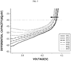
- FIG. 7 is a diagram schematically showing Coulomb efficiency of the battery cell B per cycle at which degradation acceleration is judged by the battery management apparatus 100 according to an embodiment of the present disclosure.
- Coulomb efficiency is calculated for each cycle based on a charge amount calculated according to Coulomb counting while the battery cell B is being charged and a discharge amount calculated according to Coulomb counting while battery cell B is being discharged.
- the Coulomb efficiency may be calculated according to the formula of "discharge amount ⁇ charge amount ⁇ 100" for each cycle.
- the Coulomb efficiency of BOL (0 cycle) to 600 cycles shows an increasing pattern
- the Coulomb efficiency of 600 cycles to 1500 cycles shows a maintained pattern
- the Coulomb efficiency of 1500 cycles to 1800 cycles shows a decreasing pattern. That is, since the degradation of the battery cell B is accelerated from 1500 cycles, the Coulomb efficiency of 1500 cycles to 1800 cycles shows a decreasing pattern.
- the battery management apparatus 100 has an advantage of accurately judging whether the state of the battery cell B is a degradation acceleration state based on the voltage change pattern and the differential capacity change pattern of the peak included in the plurality of differential profiles PF1 to PF7, without calculating the Coulomb efficiency for each cycle for the battery cell B. Furthermore, the battery management apparatus 100 has an advantage of judging the cycle point at which the degradation of the battery cell B is accelerated.
- FIG. 8 is a diagram schematically showing a plurality of differential voltage profiles PF1' to PF7' that represent a corresponding relationship between a capacity and a differential voltage of the battery cell B.
- the differential voltage is a value obtained by differentiating voltage by capacity with respect to voltage and capacity corresponding to each other, and may be expressed as "dV/dQ".
- the unit of the differential voltage may be [V/mAh]. That is, since the differential voltage profile is a profile representing a corresponding relationship between the differential voltage and the capacity of the battery cell B, it should be noted that the differential voltage profile is a profile different from the differential profile of FIG. 3 .
- FIG. 8 is a diagram showing first to seventh differential voltage profiles PF1' to PF7'.
- the first differential voltage profile PF1' may be a differential voltage profile for the battery cell B in a BOL state
- the second differential voltage profile PF2' may be a differential voltage profile for the battery cell B of 300 cycles
- the third differential voltage profile PF3' may be a differential voltage profile for the battery cell B of 600 cycles
- the fourth differential voltage profile PF4' may be a differential voltage profile for the battery cell B of 900 cycles.
- the fifth differential voltage profile PF5' may be a differential voltage profile for the battery cell B of 1200 cycles
- the sixth differential voltage profile PF6' may be a differential voltage profile for the battery cell B of 1500 cycles
- the seventh differential voltage profile PF7' may be a differential voltage profile for the battery cell B of 1800 cycles.
- the curvature between the fifth differential voltage profile PF5' and the sixth differential voltage profile PF6' may be largest. That is, it can be seen that the curvature difference between the fifth and sixth differential voltage profiles PF5', PF6' is largest among the curvature difference between the first and second differential voltage profiles PF1', PF2', the curvature difference between the second and third differential voltage profiles PF2', PF3', the curvature difference between the third and fourth differential voltage profiles PF3', PF4', the curvature difference between the fourth and fifth differential voltage profiles PF4', PF5', the curvature difference between the fifth and sixth differential voltage profiles PF5', PF6', and the curvature difference between the sixth and seventh differential voltage profiles PF6', PF7'.
- the fact that the curvature of the differential voltage profile becomes gentle as the cycle progresses can be explained as the internal resistance of the battery cell B increases due to the degradation of the battery cell B. That is, if the internal resistance of the battery cell B is greatly increased from 1500 cycles, it can be said that the degradation of the battery cell B is accelerated from 1500 cycles.
- the battery management apparatus 100 has an advantage of accurately judging whether the state of the battery cell B is a degradation acceleration state. Furthermore, the battery management apparatus 100 has an advantage of judging the cycle point when the degradation of the battery cell B is accelerated.
- the control unit 130 may be configured to set a discharge end voltage of the battery cell B to be greater than or equal to a voltage corresponding to the at least one target peak TP1, TP2.
- the control unit 130 may decrease the usable voltage range of the battery cell B by upwardly controlling the discharge end voltage of the battery cell B. This is because, even when the battery cell B is degraded, if the battery cell B is discharged to a low voltage region, the degradation of the battery cell B can be continuously accelerated. Thus, the control unit 130 may slow down the degradation rate of the battery cell B by increasing the discharge end voltage of the battery cell B.
- control unit 130 may determine the sixth peak P6 as the first target peak TP1 and determine the seventh peak P7 as the second target peak TP2.
- control unit 130 may set the discharge end voltage of the battery cell B to be greater than or equal to a voltage corresponding to the first target peak TP1 or a voltage corresponding to the second target peak TP2.
- control unit 130 may be configured to set the discharge end voltage for the battery cell B to be greater than or equal to the largest voltage among voltages corresponding to the at least one target peak TP1, TP2.
- the control unit 130 may set the discharge end voltage of the battery cell B to be greater than or equal to the voltage corresponding to the second target peak TP2. More preferably, the control unit 130 may set the discharge end voltage of the battery cell B to a value greater than the voltage corresponding to the second target peak TP2.
- the battery management apparatus 100 has an advantage of not only judging the state of the battery cell B, but also increasing the lifespan of the battery cell B by upwardly controlling the discharge end voltage of the battery cell B.
- the battery management apparatus 100 may be applied to a BMS (Battery Management System). That is, the BMS according to the present disclosure may include the battery management apparatus 100 described above. In this configuration, at least some of components of the battery management apparatus 100 may be implemented by supplementing or adding functions of components included in a conventional BMS. For example, the profile generating unit 110, the profile converting unit 120, the control unit 130, and the storage unit 140 of the battery management apparatus 100 may be implemented as components of the BMS.
- the battery management apparatus 100 may be provided to a battery pack 1. That is, the battery pack 1 according to the present disclosure may include the battery management apparatus 100 described above and at least one battery cell B. In addition, the battery pack 1 may further include electrical equipment (relays, fuses, etc.) and a case.
- FIG. 9 is a diagram schematically showing an exemplary configuration of a battery pack 1 including the battery management apparatus 100 according to an embodiment of the present disclosure.
- the battery pack 1 includes a positive electrode terminal and a negative electrode terminal, and may include a battery cell B, a measuring unit 200, and a battery management apparatus 100.
- the measuring unit 200 may be configured to measure the voltage and capacity of the battery cell B.
- the measuring unit 200 may measure a voltage of the battery by measuring voltages at both ends of the battery cell B, respectively. Also, the measuring unit 200 may measure a current output from the battery cell B and a discharge time while the battery cell B is being discharged. In addition, the measuring unit 200 may measure a capacity of the battery cell B based on the measured current of the battery cell B and the discharge time.
- the measuring unit 200 may be connected to a first sensing line SL1, a second sensing line SL2, and a third sensing line SL3.
- the measuring unit 200 may measure the voltage of the battery cell B through the first sensing line SL1 and the second sensing line SL2.
- the measuring unit 200 may be connected to a current measuring unit A through the third sensing line SL3, and may measure the current of the battery cell B through the current measuring unit A.
- the measuring unit 200 may include a timer capable of measuring the discharge time while measuring the current of the battery cell B.
- a charging/discharging unit 2 may be connected to a positive electrode terminal (P+) and a negative electrode terminal (P-) of the battery pack 1 to charge or discharge the battery cell B.
- the measuring unit 200 may measure the voltage and capacity of the battery cell B, and transmit battery information including the measured voltage and capacity to the profile generating unit 110. That is, the profile generating unit 110 may obtain battery information by receiving the battery information from the measuring unit 200.
- FIG. 10 is a diagram schematically showing a battery management method according to another embodiment of the present disclosure. Each step of the battery management method may be performed by the battery management apparatus 100.
- the battery management method may include a battery information obtaining step (S100), a battery profile generating step (S200), a differential profile converting step (S300), a peak selecting step (S400), a pattern determining step (S500), and a degradation acceleration determining step (S600).
- S100 battery information obtaining step
- S200 battery profile generating step
- S300 differential profile converting step
- S400 peak selecting step
- S500 pattern determining step
- S600 degradation acceleration determining step
- the battery information obtaining step (S100) is a step of obtaining battery information including voltage and capacity of a battery cell B, and may be performed by the profile generating unit 110.
- the profile generating unit 110 may receive battery information from the outside, or battery information may be directly input to the profile generating unit 110 by a user.
- the profile generating unit 110 may obtain battery information from the measuring unit 200 capable of measuring the voltage and capacity of the battery cell B.
- the profile generating step (S200) is a step of generating a battery profile representing a corresponding relationship between the voltage and the capacity based on the obtained battery information, and may be performed by the profile generating unit 110.
- the profile generating unit 110 may read voltage and capacity corresponding to each other from the obtained battery information, and generate a battery profile representing a corresponding relationship between the read voltage and capacity.
- the differential profile converting step (S300) is a step of converting the battery profile into a differential profile representing a corresponding relationship between the voltage and a differential capacity for the voltage, and may be performed by the profile converting unit 120.
- the profile converting unit 120 may receive the battery profile from the profile generating unit 110. In addition, the profile converting unit 120 may convert the battery profile into a differential profile representing a corresponding relationship between the voltage and the differential capacity.
- the peak selecting step (S400) is a step of selecting a peak included in a preset criterion voltage region in each of the plurality of differential profiles PF1 to PF7 converted in the differential profile converting step (S300), and may be performed by the control unit 130.
- control unit 130 may select first to seventh peaks P1 to P7 in the criterion voltage regions of the first to seventh differential profiles PF1 to PF7, respectively.
- the pattern determining step (S500) is a step of determining a voltage change pattern for the voltage and a differential capacity change pattern for the differential capacity of the plurality of selected peaks P1 to P7, and may be performed by the control unit 130.
- control unit 130 may determine a voltage change pattern and a differential capacity change pattern for the plurality of peaks P1 to P7 according to a cycle order for the battery cell B.
- the voltage change pattern of the first to third peaks P1 to P3 may be an increasing pattern
- the voltage change pattern between the third peak P3 and the fourth peak P4 may be a decreasing pattern
- the voltage change pattern of the fourth to seventh peaks P4 to P7 may be an increasing pattern
- the differential capacity change pattern between the first peak P1 and the second peak P2 may be a decreasing pattern
- the differential capacity change pattern of the second to seventh peaks P2 to P7 may be an increasing pattern.
- the degradation acceleration determining step (S600) is a step of judging whether degradation of the battery cell B is accelerated according to whether the determined voltage change pattern corresponds to a preset first reference pattern and whether the determined differential capacity change pattern corresponds to a preset second reference pattern, and may be performed by the control unit 130.
- control unit 130 may judge that the state of the battery cell B is a degradation acceleration state.
- control unit 130 may be configured to determine at least one target peak TP1, TP2 corresponding to the first reference pattern and the second reference pattern among the plurality of peaks P1 to P7. In addition, the control unit 130 may be configured to judge that degradation of the battery cell B is accelerated from a lowest cycle among cycles corresponding to the at least one target peak TP1, TP2.
- control unit 130 may not only judge whether the state of the battery cell B is a degradation acceleration state, but also judge the cycle at which the degradation of the battery cell B is accelerated.
- control unit 130 may increase the lifespan of the battery cell B by setting the discharge end voltage for the battery cell B to be greater than or equal to the largest voltage among voltages corresponding to the at least one target peak TP1, TP2.
- the embodiments of the present disclosure described above may not be implemented only through an apparatus and a method, but may be implemented through a program that realizes a function corresponding to the configuration of the embodiments of the present disclosure or a recording medium on which the program is recorded.
- the program or recording medium may be easily implemented by those skilled in the art from the above description of the embodiments.
Landscapes
- General Physics & Mathematics (AREA)
- Physics & Mathematics (AREA)
- Engineering & Computer Science (AREA)
- Chemical & Material Sciences (AREA)
- Chemical Kinetics & Catalysis (AREA)
- Electrochemistry (AREA)
- General Chemical & Material Sciences (AREA)
- Manufacturing & Machinery (AREA)
- Microelectronics & Electronic Packaging (AREA)
- Power Engineering (AREA)
- Secondary Cells (AREA)
- Charge And Discharge Circuits For Batteries Or The Like (AREA)
- Tests Of Electric Status Of Batteries (AREA)
Applications Claiming Priority (2)
| Application Number | Priority Date | Filing Date | Title |
|---|---|---|---|
| KR1020200115637A KR102652327B1 (ko) | 2020-09-09 | 2020-09-09 | 배터리 관리 장치 및 방법 |
| PCT/KR2021/012246 WO2022055264A1 (fr) | 2020-09-09 | 2021-09-08 | Dispositif et procédé de gestion de batteries |
Publications (3)
| Publication Number | Publication Date |
|---|---|
| EP4155748A1 true EP4155748A1 (fr) | 2023-03-29 |
| EP4155748A4 EP4155748A4 (fr) | 2023-12-13 |
| EP4155748B1 EP4155748B1 (fr) | 2024-08-14 |
Family
ID=80631971
Family Applications (1)
| Application Number | Title | Priority Date | Filing Date |
|---|---|---|---|
| EP21867129.5A Active EP4155748B1 (fr) | 2020-09-09 | 2021-09-08 | Dispositif et procédé de gestion de batteries |
Country Status (6)
| Country | Link |
|---|---|
| US (1) | US20230280403A1 (fr) |
| EP (1) | EP4155748B1 (fr) |
| JP (1) | JP7362990B2 (fr) |
| KR (1) | KR102652327B1 (fr) |
| CN (1) | CN115917344A (fr) |
| WO (1) | WO2022055264A1 (fr) |
Families Citing this family (3)
| Publication number | Priority date | Publication date | Assignee | Title |
|---|---|---|---|---|
| KR102694988B1 (ko) * | 2022-11-01 | 2024-08-12 | 주식회사 엘지에너지솔루션 | 배터리 진단 장치 및 방법 |
| KR20240101262A (ko) * | 2022-12-23 | 2024-07-02 | 주식회사 엘지에너지솔루션 | 배터리 진단 장치 및 방법 |
| KR20240122248A (ko) * | 2023-02-03 | 2024-08-12 | 주식회사 엘지에너지솔루션 | 배터리 진단 장치 및 이의 동작 방법 |
Family Cites Families (16)
| Publication number | Priority date | Publication date | Assignee | Title |
|---|---|---|---|---|
| JP5397679B2 (ja) * | 2009-05-21 | 2014-01-22 | 株式会社Gsユアサ | 二次電池の劣化診断方法、及び二次電池の劣化診断装置 |
| CN102369627B (zh) * | 2009-09-25 | 2013-09-11 | 丰田自动车株式会社 | 二次电池系统 |
| JP5682955B2 (ja) * | 2010-08-04 | 2015-03-11 | Necエナジーデバイス株式会社 | リチウム二次電池の制御システム、およびリチウム二次電池の状態検出方法 |
| US8531158B2 (en) * | 2010-11-01 | 2013-09-10 | GM Global Technology Operations LLC | Method and apparatus for assessing battery state of health |
| JP5662968B2 (ja) | 2012-06-19 | 2015-02-04 | 株式会社日立製作所 | 二次電池の検査システム、充放電機、及び検査方法 |
| JP5354416B1 (ja) * | 2012-11-05 | 2013-11-27 | 東洋システム株式会社 | 二次電池評価方法および評価プログラム |
| WO2014083813A1 (fr) * | 2012-11-30 | 2014-06-05 | 株式会社Gsユアサ | Dispositif de détection de la diminution de la fonctionnalité d'un élément de stockage, procédé de détection d'une diminution de fonctionnalité, et système de stockage |
| JP2015060761A (ja) * | 2013-09-19 | 2015-03-30 | 株式会社東芝 | 二次電池の劣化診断システム及び劣化診断方法 |
| WO2015080285A1 (fr) * | 2013-11-29 | 2015-06-04 | 日立オートモティブシステムズ株式会社 | Module de batterie et batterie assemblée |
| JP6405754B2 (ja) * | 2014-07-02 | 2018-10-17 | 日本電気株式会社 | 電池制御装置及び電池制御システム |
| JP6123844B2 (ja) * | 2014-09-01 | 2017-05-10 | 横河電機株式会社 | 二次電池容量測定システム及び二次電池容量測定方法 |
| WO2016135913A1 (fr) * | 2015-02-26 | 2016-09-01 | 株式会社 東芝 | Batterie de stockage, procédé de surveillance de batterie de stockage et contrôleur de surveillance |
| JP2018205138A (ja) * | 2017-06-05 | 2018-12-27 | 三菱自動車工業株式会社 | 二次電池システム |
| PT3749599T (pt) | 2018-02-08 | 2023-09-19 | Invista Textiles Uk Ltd | Transcarregamento de sólidos |
| KR102349300B1 (ko) * | 2018-04-10 | 2022-01-10 | 주식회사 엘지에너지솔루션 | 배터리의 전극 정보를 결정하기 위한 장치, 방법, 배터리 팩 및 전기 시스템 |
| KR102259415B1 (ko) * | 2018-08-29 | 2021-06-01 | 주식회사 엘지에너지솔루션 | 배터리 관리 장치, 배터리 관리 방법, 배터리 팩 및 전기 차량 |
-
2020
- 2020-09-09 KR KR1020200115637A patent/KR102652327B1/ko active IP Right Grant
-
2021
- 2021-09-08 EP EP21867129.5A patent/EP4155748B1/fr active Active
- 2021-09-08 JP JP2022551699A patent/JP7362990B2/ja active Active
- 2021-09-08 CN CN202180036606.9A patent/CN115917344A/zh active Pending
- 2021-09-08 US US17/926,309 patent/US20230280403A1/en active Pending
- 2021-09-08 WO PCT/KR2021/012246 patent/WO2022055264A1/fr unknown
Also Published As
| Publication number | Publication date |
|---|---|
| WO2022055264A1 (fr) | 2022-03-17 |
| KR20220033350A (ko) | 2022-03-16 |
| EP4155748B1 (fr) | 2024-08-14 |
| JP7362990B2 (ja) | 2023-10-18 |
| US20230280403A1 (en) | 2023-09-07 |
| EP4155748A4 (fr) | 2023-12-13 |
| JP2023515595A (ja) | 2023-04-13 |
| CN115917344A (zh) | 2023-04-04 |
| KR102652327B1 (ko) | 2024-03-27 |
Similar Documents
| Publication | Publication Date | Title |
|---|---|---|
| EP4155748B1 (fr) | Dispositif et procédé de gestion de batteries | |
| JP7293566B2 (ja) | バッテリー退化度診断装置及び方法 | |
| US11990590B2 (en) | Battery management apparatus and method | |
| CN114270204B (zh) | 用于诊断电池状态的设备和方法、包括该设备的电池组 | |
| JP7443648B2 (ja) | バッテリー管理装置及び方法 | |
| JP7392248B2 (ja) | バッテリー管理装置及び方法 | |
| EP3998489A1 (fr) | Dispositif et procédé de diagnostic de degré de détérioration de batterie | |
| EP4145589A1 (fr) | Dispositif et procédé de classification de batterie | |
| EP4135099A1 (fr) | Dispositif et procédé de gestion de batterie | |
| EP4152020A1 (fr) | Appareil et procédé de gestion de batterie | |
| EP4198536A1 (fr) | Appareil et procédé de gestion de batterie | |
| EP4152025A1 (fr) | Dispositif et procédé de diagnostic de batterie | |
| CN118633031A (zh) | 用于诊断电池的装置和方法 |
Legal Events
| Date | Code | Title | Description |
|---|---|---|---|
| STAA | Information on the status of an ep patent application or granted ep patent |
Free format text: STATUS: THE INTERNATIONAL PUBLICATION HAS BEEN MADE |
|
| PUAI | Public reference made under article 153(3) epc to a published international application that has entered the european phase |
Free format text: ORIGINAL CODE: 0009012 |
|
| STAA | Information on the status of an ep patent application or granted ep patent |
Free format text: STATUS: REQUEST FOR EXAMINATION WAS MADE |
|
| 17P | Request for examination filed |
Effective date: 20221220 |
|
| AK | Designated contracting states |
Kind code of ref document: A1 Designated state(s): AL AT BE BG CH CY CZ DE DK EE ES FI FR GB GR HR HU IE IS IT LI LT LU LV MC MK MT NL NO PL PT RO RS SE SI SK SM TR |
|
| A4 | Supplementary search report drawn up and despatched |
Effective date: 20231114 |
|
| DAV | Request for validation of the european patent (deleted) | ||
| DAX | Request for extension of the european patent (deleted) | ||
| RIC1 | Information provided on ipc code assigned before grant |
Ipc: H01M 10/44 20060101ALI20231108BHEP Ipc: H01M 10/42 20060101ALI20231108BHEP Ipc: H01M 10/48 20060101ALI20231108BHEP Ipc: G01R 31/382 20190101ALI20231108BHEP Ipc: G01R 19/30 20060101ALI20231108BHEP Ipc: G01R 19/165 20060101ALI20231108BHEP Ipc: G01R 31/36 20200101ALI20231108BHEP Ipc: G01R 31/367 20190101ALI20231108BHEP Ipc: G01R 31/392 20190101AFI20231108BHEP |
|
| GRAP | Despatch of communication of intention to grant a patent |
Free format text: ORIGINAL CODE: EPIDOSNIGR1 |
|
| STAA | Information on the status of an ep patent application or granted ep patent |
Free format text: STATUS: GRANT OF PATENT IS INTENDED |
|
| INTG | Intention to grant announced |
Effective date: 20240605 |
|
| GRAS | Grant fee paid |
Free format text: ORIGINAL CODE: EPIDOSNIGR3 |
|
| GRAA | (expected) grant |
Free format text: ORIGINAL CODE: 0009210 |
|
| STAA | Information on the status of an ep patent application or granted ep patent |
Free format text: STATUS: THE PATENT HAS BEEN GRANTED |
|
| P01 | Opt-out of the competence of the unified patent court (upc) registered |
Free format text: CASE NUMBER: APP_38561/2024 Effective date: 20240627 |
|
| AK | Designated contracting states |
Kind code of ref document: B1 Designated state(s): AL AT BE BG CH CY CZ DE DK EE ES FI FR GB GR HR HU IE IS IT LI LT LU LV MC MK MT NL NO PL PT RO RS SE SI SK SM TR |
|
| REG | Reference to a national code |
Ref country code: GB Ref legal event code: FG4D |
|
| REG | Reference to a national code |
Ref country code: CH Ref legal event code: EP |
|
| REG | Reference to a national code |
Ref country code: DE Ref legal event code: R096 Ref document number: 602021017347 Country of ref document: DE |
|
| REG | Reference to a national code |
Ref country code: IE Ref legal event code: FG4D |
|
| PGFP | Annual fee paid to national office [announced via postgrant information from national office to epo] |
Ref country code: NL Payment date: 20240822 Year of fee payment: 4 |