EP4153330B1 - Trainingsgerät - Google Patents
Trainingsgerät Download PDFInfo
- Publication number
- EP4153330B1 EP4153330B1 EP21728197.1A EP21728197A EP4153330B1 EP 4153330 B1 EP4153330 B1 EP 4153330B1 EP 21728197 A EP21728197 A EP 21728197A EP 4153330 B1 EP4153330 B1 EP 4153330B1
- Authority
- EP
- European Patent Office
- Prior art keywords
- track
- central
- slide block
- pad
- tracks
- Prior art date
- Legal status (The legal status is an assumption and is not a legal conclusion. Google has not performed a legal analysis and makes no representation as to the accuracy of the status listed.)
- Active
Links
Images


Classifications
-
- A—HUMAN NECESSITIES
- A63—SPORTS; GAMES; AMUSEMENTS
- A63B—APPARATUS FOR PHYSICAL TRAINING, GYMNASTICS, SWIMMING, CLIMBING, OR FENCING; BALL GAMES; TRAINING EQUIPMENT
- A63B21/00—Exercising apparatus for developing or strengthening the muscles or joints of the body by working against a counterforce, with or without measuring devices
- A63B21/00192—Exercising apparatus for developing or strengthening the muscles or joints of the body by working against a counterforce, with or without measuring devices using resistance provided by magnetic means
-
- A—HUMAN NECESSITIES
- A63—SPORTS; GAMES; AMUSEMENTS
- A63B—APPARATUS FOR PHYSICAL TRAINING, GYMNASTICS, SWIMMING, CLIMBING, OR FENCING; BALL GAMES; TRAINING EQUIPMENT
- A63B21/00—Exercising apparatus for developing or strengthening the muscles or joints of the body by working against a counterforce, with or without measuring devices
- A63B21/15—Arrangements for force transmissions
- A63B21/151—Using flexible elements for reciprocating movements, e.g. ropes or chains
- A63B21/153—Using flexible elements for reciprocating movements, e.g. ropes or chains wound-up and unwound during exercise, e.g. from a reel
-
- A—HUMAN NECESSITIES
- A63—SPORTS; GAMES; AMUSEMENTS
- A63B—APPARATUS FOR PHYSICAL TRAINING, GYMNASTICS, SWIMMING, CLIMBING, OR FENCING; BALL GAMES; TRAINING EQUIPMENT
- A63B21/00—Exercising apparatus for developing or strengthening the muscles or joints of the body by working against a counterforce, with or without measuring devices
- A63B21/15—Arrangements for force transmissions
- A63B21/151—Using flexible elements for reciprocating movements, e.g. ropes or chains
- A63B21/154—Using flexible elements for reciprocating movements, e.g. ropes or chains using special pulley-assemblies
-
- A—HUMAN NECESSITIES
- A63—SPORTS; GAMES; AMUSEMENTS
- A63B—APPARATUS FOR PHYSICAL TRAINING, GYMNASTICS, SWIMMING, CLIMBING, OR FENCING; BALL GAMES; TRAINING EQUIPMENT
- A63B21/00—Exercising apparatus for developing or strengthening the muscles or joints of the body by working against a counterforce, with or without measuring devices
- A63B21/40—Interfaces with the user related to strength training; Details thereof
- A63B21/4027—Specific exercise interfaces
- A63B21/4033—Handles, pedals, bars or platforms
- A63B21/4035—Handles, pedals, bars or platforms for operation by hand
-
- A—HUMAN NECESSITIES
- A63—SPORTS; GAMES; AMUSEMENTS
- A63B—APPARATUS FOR PHYSICAL TRAINING, GYMNASTICS, SWIMMING, CLIMBING, OR FENCING; BALL GAMES; TRAINING EQUIPMENT
- A63B69/00—Training appliances or apparatus for special sports
- A63B69/18—Training appliances or apparatus for special sports for skiing
- A63B69/182—Training appliances or apparatus for special sports for skiing for cross-country-skiing
Definitions
- the prior art knows the apparatus described by the document FR 3064923 .
- This device is long and bulky, in particular to allow a sufficiently wide stroke length of the poles which are fixed to a mobile means in translation on a track close to the ground on which the device rests.
- this device does not allow continuous and effective resistance to movement over the entire length of the movement of the poles.
- the poles are positioned on wheeled trolleys which are therefore driven towards the low point of the track supporting them.
- the present invention aims to remedy all or part of these drawbacks.
- the training device induces a sensation similar to that of cross-country skiing.
- the efforts required to move the skates and/or sliders can be adapted since the dynamic friction force is directly proportional to the weight supported.
- resistance to movement by friction is simple to implement and is continuous and effective over the entire length of the movement of the poles.
- the friction means comprise magnetic braking means.
- At least a portion of at least one side track is elevated relative to the center tracks.
- the device makes it possible to shorten the length of the poles while maintaining a range of movement of the user's arms corresponding to that of cross-country skiing.
- the size of the training device which is the subject of the invention is reduced.
- each skate and each slider are connected by at least one cable configured to synchronize the movements of each skate and each slider.
- the training device faithfully reproduces the movement of cross-country skiing and walking with poles, such that, during normal use, the advancing leg is accompanied in its forward movement by the arm on the opposite side while the retreating leg is accompanied in its backward movement by the other arm.
- the cable forms a loop.
- the drive device is simplified, since it does not require a winder or mass at each end of the cable.
- the device object of the invention comprises two automatic winders configured to wind the two ends of the cable.
- the device according to the invention comprises a means for tilting each central track and/or each lateral track.
- At least one slider comprises magnetic braking means.
- At least one slider is connected to one end of a stick, the other free end of which carries a handle connected to the stick via a pivot connection or via a ball joint connection.
- the pivot connection allows for lateral and/or ulnar flexion of the handle.
- the user of the training device can thus perform a palmar flexion movement to push the poles back at the apex of the arm and wrist movement during the exercise.
- At least one slider is connected to one end of a pole via a pivot connection or via a ball joint connection.
- the device object of the invention comprises two lateral tracks parallel to the central tracks and positioned on either side of the central tracks.
- the training device imitates the movement of poles similar to cross-country skiing or walking with poles.
- the device of the invention comprises a side track perpendicular to the central tracks and positioned at one end of each central track.
- the training device reproduces the sensations of mountain walking or hiking, for example.
- At least one friction means is positioned on each slider and comprises a bearing surface on the lateral track, at least one weight being positioned on said friction means.
- the bearing surface is integrated with each slider and the shape of the bearing surface matches the shape of a surface of the track on which the slider slides.
- the positioning of the slider in the side track is stabilized by gravity.
- the contact surface between the slider and the side track is increased, which allows the friction means to be better positioned.
- the cable is attached to the slider and forms a non-zero angle with the side track.
- At least one friction means comprises means for suspending at least one weight from each skate, the suspension means contacting the central track in which the skate slides.
- the device is more compact.
- the suspension means comprises a plate suspended between the skate and the central track in which the skate slides.
- the friction means comprises means for clamping a plate against the central track, the clamping of the plate increasing the friction force.
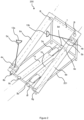
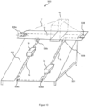
- figure 1 which is not to scale, a schematic view of a first particular embodiment of the training device 100 imitating the movements associated with the practice of cross-country skiing, object of the invention.
- the drive device 100 comprises a chassis 101 on which are mounted two central tracks, 1a and 1b, arranged on either side and close to a central axis of the chassis.
- the two central tracks, 1a and 1b are arranged on a lower part of the chassis, preferably as close as possible to the ground on which the drive device 100 rests.
- the central tracks, 1a and 1b are parallel to each other.
- each central track 1a and 1b, is mounted a skate, respectively 3a and 3b, configured to accommodate the foot of a user of the training device.
- the skate is movable in translation along the central track with which it is associated.
- the central tracks, 1a and 1b, and the skates, 3a and 3b, are described opposite the figure 8 .
- the skates, 3a and 3b have an ergonomic shape adapted to the user's foot and include attachment means well known to those skilled in the art, for example straps.
- the foot support surface on each skate is made free to rotate on a horizontal axis or comprises a ball joint to accommodate the flexion and extension movements of the foot.
- Two side tracks, 6a and 6b are mounted on either side of the central tracks, 1a and 1b.
- the side tracks, 6a and 6b are raised on railings fixed to the chassis 51.
- Two slides, 4a and 4b are mounted on the side tracks, respectively 6a and 6b.
- Each slide, 4a and 4b is movable in translation along the side track, 6a and 6b, on which it is mounted.
- Each slide, 4a and 4b is connected to a stick, 5a and 5b, by means of a hinge connection.
- Each slide, 4a and 4b is provided with friction means configured to induce a dynamic friction force on the side tracks, 6a and 6b, on which the slide slides.
- the poles are configured to be grasped by their free end, by a user during normal use of the training device 100.
- the coordinated movement of the legs, supported by the skates, and the arms, gripping the poles, is done forwards and then backwards.
- the training device 100 faithfully reproduces the movement of cross-country skiing and walking with poles, such that so that, during normal use, the advancing leg is accompanied in its forward movement by the arm on the opposite side while the retreating leg is accompanied in its backward movement by the other arm.
- a cable 7 connects the first slider 4a to the first shoe 3a by means of pulleys 8a, 8b and 8c.
- the same cable 7 is attached to the second shoe 3b by means of pulleys, 8d and 8e.
- the same cable 7 is attached to the second slider by means of pulleys 8f, 8g and 8h.
- the cable 7 forms a loop and is attached to the slide 4a by means of pulleys 8i and 8j.
- the cable 7 is automatically wound at its two ends by automatic winders (not shown). For example, they operate by means of springs or weights.
- a cable is defined as a long, thin link capable of transmitting a tensile force. It may be, for example, a simple metal cable or a cable braided with metal fibres, a rope or a ribbon, for example a synthetic rubber ribbon, a chain or any other equivalent means known to those skilled in the art.
- the cable 7 is wound around the pulleys, 8a to h or 8a to 8j, or around equivalent means such as guides or toothed wheels.
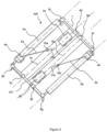
- FIG 2 which is not to scale, a schematic view of a second particular embodiment of the drive device 200 which is the subject of the invention.
- the drive device 200 is distinguished in particular from that described in figure 1 in that the lateral tracks, 6a and 6b, carried by the chassis 201, are inclined.
- the sticks, 5a and 5b comprise, on their free ends, a handle, respectively 13a and 13b, perpendicular to the axis of the stick.
- FIG 3 a schematic view of a third particular embodiment of the drive device 300 which is the subject of the invention.
- This drive device 300 is distinguished from those described in figures 1 And 2 in that the side tracks, 6a and 6b, are arranged in the same plane as the central tracks 1a and 1b. These tracks are supported by a chassis 301.
- the sticks, 5a and 5b comprise, on their free ends, a handle, respectively 21a and 21b, connected to the stick, 5a or 5b, by means of a pivot connection 19a or 19b.
- the sticks, 5a and 5b comprise on their free ends a handle, respectively 21a and 21b, connected to the stick, 5a or 5b, by means of a ball joint.
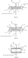
- FIG 4 a first particular embodiment of a slide 4a mounted movable in translation on a lateral track 6a.
- the slide 4a comprises a hinge connection 20 connected to the stick 5a.
- the lateral track 6a is mounted on the chassis 101, 201, 301, 401 or 501.
- the slide 4a comprises a body 22 in the shape of an inverted "U" complementary to the shape of the lateral track 6a.
- the body 22 comprises a coating 14 on its face 12 oriented towards the lateral track 6a.
- the coating 14 slides in contact with the surface 15 of the lateral track 6a, constrained by the two ends of the body 22 in the shape of a "U", thus forming a sliding connection.
- the coating 14 is an unalterable and flexible polyester material.
- the surface 15 comprises Teflon or high density polyethylene (acronym "HDPE") or a melamine paint.
- Other materials meeting the same tribological principles can be used for the coating 14 and the surface 15.
- the body 22 comprises magnetic braking means 16 allowing the braking of the slide by magnetization with a ferromagnetic material secured to the lateral track 6a.
- the ferromagnetic material is a metal sheet 17.
- the braking is carried out by direct magnetization, that is to say without an air strip separating the slide 4a comprising the magnetic means 16 from the lateral track 6a comprising the metal sheet 17.
- an air strip is arranged between the slide 4a comprising the magnetic means 16 and the lateral track 6a comprising the metal sheet 17.
- the air strip is obtained by interposing at least one shim between the magnetic means and the metal sheet.
- the air strip is obtained by suspending the magnetic means, for example by means of a threaded rod passing through a tapped hole. The distance of the magnet from the metal sheet reduces the friction force.
- the magnetic braking means comprise at least one electromagnet and the means necessary for its electrical supply and for the modulation of this electrical supply.
- FIG. 5 a particular embodiment of a slide 4a mounted movably in translation on a lateral track 6a.
- the slide 4a comprises a hinge connection 20 connected to the stick 5a.
- the lateral track 6a is mounted on the chassis 51.
- the slide 4a comprises a body 23 in the shape of an inverted "U" complementary to the shape of the lateral track 6a.
- the body 23 supports weights 18 whose mass applies, by gravity, a force (also called “weight”) oriented downwards, that is to say towards the lateral track 6a.
- a force also called “weight”
- the force thus exerted by the weights increases the friction forces between the slide 4a and the lateral track 6a, slowing the movement of the slide 4a on the lateral track 6a.
- the mass of the supported removable weights 18 may be adjusted by adding, removing, or substituting weights attached to the slider 4a.
- the body 23 has a coating 14 on its face 12 and the lateral track 6a has a surface 15. These elements being similar to those described in figure 4 they are not described again here.
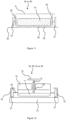
- FIG. 6 a particular embodiment of a slide 4a mounted mobile in translation on a lateral track 6a.
- the slide 4a comprises a hinge connection 20 connected to the stick 5a.
- the lateral track 6a is integral with the chassis 51.
- the slide 4a comprises a hollow body 25 of rectangular section. The upper side 12 of the body 25 rests and slides on the lateral track 6a.
- the body 25 supports weights 18 which, by gravity, exert a force oriented downwards, that is to say towards the lateral track 6a.
- the force thus exerted by the weights increases the friction forces between the slide 4a and the lateral track 6a, slowing the advance of the slide 4a.
- the weights 18 rest inside the hollow body 25.
- the body 25 has a coating 14 on its face 12 and the lateral track 6a has a surface 15. These elements being similar to those described in figure 4 , they are not described again here.
- At least one slider, 4a or 4b includes wheels, casters or ball bearings rolling on the side track, 6a or 6b.
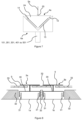
- FIG 7 a particular embodiment of a slide 4a mounted movably in translation on a lateral track 6a.
- the slide 4a comprises a hinge connection 20 connected to the stick 5a.
- the lateral track 6a is mounted on the chassis 51.
- the slide 4a comprises a body 24 of triangular shape complementary to a notch in the shape of a "V" in the lateral track 6a.
- the body 24 has a coating 14 on its face 12 and the lateral track 6a has a surface 15. These elements being similar to those described in figure 4 , they are not described again here.
- the slider 4a and the side track 6a illustrated in figure 7 include braking means comprising weights, as described in the description of the figure 5 .
- the slider 4a and the side track 6a illustrated in figure 7 include magnetic braking means, as described in the description of the figure 6 .
- the skates 3a and 3b comprise wheels 31 which move in translation in a trench delimited by blocks 32.
- the wheels 31 are connected by a frame 30 connecting the wheels 31 to a plate 9.
- a platform 33 is interposed between the plates 9 of the skates, 3a and 3b, and the tracks, 1a and 1b.
- the frames 30 comprise a thin part passing through a slot of corresponding dimension cut in the platform 33.
- the skates, 1a and 1b move on rails, or are mounted to move in translation in a slide.
- FIG 9 a fourth particular embodiment 400 of the device which is the subject of the invention.
- This device 400 is more particularly intended to reproduce walking with poles in the mountains.
- This device 400 comprises a chassis 401 and central tracks 1a and 1b supported by an inclined plane 402 and whose pads 3a and 3b are provided with a horizontal upper face so that the feet do not slip and the user does not risk falling.
- the inclination of the inclined plane 402 is adjustable by a tilting system, for example with mechanical stops carried by the chassis 401.
- the inclination of the upper face of each pad 3a and 3b is also adjustable.
- the side tracks for the slides may be horizontal, shorter than in other embodiments.
- the pads 3a and 3b supported by the inclined plane 402 may move in grooves in which lower lugs or blades of the pads slide.
- FIG 10 a fifth particular embodiment 500 of the device which is the subject of the invention.
- This device 500 comprises a frontal lateral track 6c perpendicular to the central tracks 1a and 1b.
- This horizontal lateral track 6c is carried by the chassis 501.
- skates 3a and 3b carried by the oblique plane 502 are in relation with a single slide 4c without a stick, which slides on a horizontal plane and perpendicular to the central tracks 1a and 1b.
- This device 500 allows greater strides than current devices.
- the inclined plane 402 or 502 may include notches forming an axis positioned perpendicular to each central track.
- a removable locking bar may be positioned in the notches to limit the length of the step and to ensure firm support on the pads when starting the apparatus.
- the skates 3a or 3b comprise wheels 31 which move in translation in a trench delimited by blocks 32.
- the wheels 31 are connected by a frame 30 connecting the wheels 31 to a plate 9.
- the frame 30 comprises a means 60 for suspending weights from each skate, the weights and/or the means 60 for suspending coming into contact with the central track in which the skate 3a or 3b slides.
- the suspension means 60 is preferably a box suspended from the frame 30 by elastic means, such as springs.
- the box comprises a plate 62 parallel to the track 32. When weights 61 are positioned in the box, the box moves towards the track 32. The plate 62 comes into contact with the track 32 and causes dynamic friction.
- the elastic means have a stiffness configured so that the box 60, when empty, that is to say without weight, is not in contact with the track 32.
- the tray 9 is removable to allow the user to remove or add weights 61.
- the skates 3a or 3b or the slides 4a and 4b comprise wheels 31 which move in translation in a trench delimited by blocks 76.
- the wheels 31 are connected by a frame 30 connecting the wheels 31 to a platform 9 where the user places his feet.
- the friction means comprise a clamping means, 72, 74 and 75, of a plate 71 against the central track 73, the clamping of the plate increasing the friction force.
- the crank 74 By actuating the crank 74, the plate 71 bears against the surface 73 of the central track. The further the plate is from the support 70, the greater the clamping and friction force.
Landscapes
- Health & Medical Sciences (AREA)
- General Health & Medical Sciences (AREA)
- Physical Education & Sports Medicine (AREA)
- Life Sciences & Earth Sciences (AREA)
- Biophysics (AREA)
- Orthopedic Medicine & Surgery (AREA)
- Rehabilitation Tools (AREA)
Claims (15)
- Trainingsvorrichtung (100, 200, 300, 400, 500), die aufweist:- ein Gestell (101, 201, 301, 401, 501) mit zwei mittleren Bahnen (1a, 1b) und mindestens einer seitlichen Bahn (6a, 6b, 6c), die auf der einen und/oder der anderen Seite der beiden mittleren Bahnen positioniert ist,- für jede mittlere Bahn einen Gleiter (3a, 3b), der auf dieser mittleren Bahn gleitet,- mindestens einen Schlitten (4a, 4b, 4c), der auf einer seitlichen Bahn gleitet und- für mindestens ein Element von einem Schlitten und/oder von mindestens einem Gleiter Reibungsmittel (16, 17, 18), die derart ausgelegt sind, dass sie eine dynamische Reibungskraft auf der Bahn bewirken, auf der das Element gleitet, und dadurch gekennzeichnet, dass die Reibungsmittel (18) mindestens ein lösbares Gewicht aufweisen.
- Vorrichtung (100, 200, 300, 400, 500) nach Anspruch 1, wobei die Reibungsmittel (18) magnetisierte Bremsmittel (16, 17) aufweisen.
- Vorrichtung (100, 200, 300, 400, 500) nach einem der Ansprüche 1 oder 2, wobei mindestens ein Teil mindestens einer seitlichen Bahn (6a, 6b, 6c) im Verhältnis zu den mittleren Bahnen (1a, 1b) erhöht ist.
- Vorrichtung (100, 200, 300, 400, 500) nach einem der Ansprüche 1 bis 3, wobei jeder Gleiter und jeder Schlitten durch ein Seil (7) verbunden sind, das ausgelegt ist, um die Bewegungen jedes Gleiters und jedes Schlittens zu synchronisieren.
- Vorrichtung (100, 200, 300, 400, 500) nach Anspruch 4, wobei das Seil (7) eine Schleife bildet, wobei seine Enden fest verbunden sind.
- Vorrichtung (100, 200, 400, 500) nach einem der Ansprüche 1 bis 5, die ein Neigungsmittel jeder mittleren Bahn (1a, 1b) und/oder jeder seitlichen Bahn (6a, 6b) aufweist.
- Vorrichtung (200, 300) nach einem der Ansprüche 1 bis 6, wobei mindestens ein Schlitten (4a, 4b) mit einem Ende einer Stange (5a, 5b) verbunden ist, deren anderes freies Ende einen Griff (21a, 21b) trägt, der über eine Schwenkverbindung oder über eine Kugelgelenkverbindung mit der Stange verbunden ist.
- Vorrichtung (200, 300) nach einem der Ansprüche 1 bis 7, wobei mindestens ein Schlitten (4a, 4b) über eine Schwenkverbindung oder über eine Kugelgelenkverbindung mit einem Ende einer Stange (5a, 5b) verbunden ist.
- Vorrichtung (500) nach einem der Ansprüche 1 bis 8, die eine seitliche Bahn (6c) senkrecht zu den mittleren Bahnen (1a, 1b) aufweist und an einem Ende jeder mittleren Bahn positioniert ist.
- Vorrichtung (100, 200, 300, 400, 500) nach einem der Ansprüche 1 bis 9, wobei mindestens ein Reibungsmittel auf jedem Schlitten positioniert ist und eine Auflagefläche (14, 71) auf der seitlichen Bahn aufweist.
- Vorrichtung (100, 200, 300, 400, 500) nach Anspruch 10, wobei die Auflagefläche (14, 71) in jeden Schlitten integriert ist und die Form der Auflagefläche (14, 71) der Form einer Oberfläche (15, 73) der Bahn, auf der der Schlitten gleitet, entspricht.
- Vorrichtung (500) nach einem der Ansprüche 10 oder 11, wobei das Seil (7) am Schlitten (4c) befestigt ist und einen Winkel ungleich Null mit der seitlichen Bahn bildet.
- Vorrichtung (100, 200, 300, 400, 500) nach einem der Ansprüche 1 bis 12, wobei mindestens ein Reibungsmittel ein Mittel (60) zum Aufhängen von Gewicht (61) an jedem Gleiter (3a oder 3b) aufweist, wobei das Aufhängungsmittel mit der mittleren Bahn (32) in Berührung kommt, in der der Gleiter gleitet.
- Vorrichtung (100, 200, 300, 400, 500) nach Anspruch 13, wobei die Aufhängungsmittel (60) eine Platte (62) aufweisen, die zwischen dem Gleiter und der mittleren Bahn, in der der Gleiter gleitet, aufgehängt ist.
- Vorrichtung (100, 200, 300, 400, 500) nach einem der Ansprüche 1 bis 12, wobei die Reibungsmittel ein Spannmittel (72, 74, 75) einer Platte (71) gegen die mittlere Bahn (73) umfassen, wobei das Spannen der Platte die Reibungskraft erhöht.
Applications Claiming Priority (2)
| Application Number | Priority Date | Filing Date | Title |
|---|---|---|---|
| FR2005218A FR3110449B1 (fr) | 2020-05-20 | 2020-05-20 | Dispositif d'entrainement imitant le ski de fond |
| PCT/EP2021/063541 WO2021234121A1 (fr) | 2020-05-20 | 2021-05-20 | Dispositif d'entraînement |
Publications (3)
| Publication Number | Publication Date |
|---|---|
| EP4153330A1 EP4153330A1 (de) | 2023-03-29 |
| EP4153330C0 EP4153330C0 (de) | 2024-12-25 |
| EP4153330B1 true EP4153330B1 (de) | 2024-12-25 |
Family
ID=72266473
Family Applications (1)
| Application Number | Title | Priority Date | Filing Date |
|---|---|---|---|
| EP21728197.1A Active EP4153330B1 (de) | 2020-05-20 | 2021-05-20 | Trainingsgerät |
Country Status (4)
| Country | Link |
|---|---|
| EP (1) | EP4153330B1 (de) |
| ES (1) | ES3013873T3 (de) |
| FR (1) | FR3110449B1 (de) |
| WO (1) | WO2021234121A1 (de) |
Family Cites Families (6)
| Publication number | Priority date | Publication date | Assignee | Title |
|---|---|---|---|---|
| US5203751A (en) * | 1991-07-15 | 1993-04-20 | Chester Chang | Exercise mechanism |
| FR2735439B1 (fr) * | 1995-06-19 | 1997-08-01 | Duault Maurice | Appareil de deplacement a patins mobiles et bras pivotants |
| US6368253B1 (en) * | 1998-02-19 | 2002-04-09 | Mathew Harrigan | In-line roller skate exercise device |
| JP4611379B2 (ja) * | 2004-05-04 | 2011-01-12 | クラフト、ウント、アウスダウアー、シュポルトゲレーテ、ゲゼルシャフト、ミット、ベシュレンクテル、ハフツング | 競技者のための運動用スティック |
| FR3017303A1 (fr) * | 2014-02-07 | 2015-08-14 | Gilbert Guy Douyere | Appareil d'entrainement physique et de reeducation |
| FR3064923A1 (fr) | 2017-04-10 | 2018-10-12 | Gilbert Guy Douyere | Appareil de gymnastique et de reeducation |
-
2020
- 2020-05-20 FR FR2005218A patent/FR3110449B1/fr active Active
-
2021
- 2021-05-20 WO PCT/EP2021/063541 patent/WO2021234121A1/fr not_active Ceased
- 2021-05-20 ES ES21728197T patent/ES3013873T3/es active Active
- 2021-05-20 EP EP21728197.1A patent/EP4153330B1/de active Active
Also Published As
| Publication number | Publication date |
|---|---|
| EP4153330A1 (de) | 2023-03-29 |
| EP4153330C0 (de) | 2024-12-25 |
| ES3013873T3 (en) | 2025-04-15 |
| FR3110449A1 (fr) | 2021-11-26 |
| FR3110449B1 (fr) | 2022-05-27 |
| WO2021234121A1 (fr) | 2021-11-25 |
Similar Documents
| Publication | Publication Date | Title |
|---|---|---|
| EP0255532A1 (de) | Muskeltrainingsgerät | |
| WO2004030774A1 (fr) | Planche a roue a propulsion | |
| EP2732856B1 (de) | Schuhbindung auf einem Snowboard, und eine solche Bindung umfassendes Snowboard | |
| FR2684885A1 (fr) | Dispositif visant a repartir la pression d'un ski sur une surface de glisse. | |
| EP1704077B1 (de) | Gleitvorrichtung für schneesportarten | |
| WO1984004693A1 (fr) | Ski court et large, a profil particulier, muni d'une plaque de retenue amovible | |
| EP4153330B1 (de) | Trainingsgerät | |
| FR2819700A1 (fr) | Dispositif de portage pour sac a dos | |
| FR2569569A1 (fr) | Exerciseur destine notamment au travail du grand ecart. | |
| CH628819A5 (fr) | Patin a roulettes et accessoire pour le patin a roulettes. | |
| EP2724759B1 (de) | Gleitvorrichtung und -einheit | |
| EP0130897A2 (de) | Vorrichtung zum mechanischen Anheben von kleinen Fahrzeugen | |
| FR2979584A1 (fr) | Unite de roulage perfectionnee et ensemble mobile roulant en comprenant. | |
| EP1333895A1 (de) | Freizeitsnowboard | |
| FR2856605A1 (fr) | Appareil d'entrainement, d'exercice et d'assistance pour la pratique du patin a roulettes | |
| FR2958176A1 (fr) | Dispositif de freinage par commande manuelle, agissant simultanement sur l'ensemble des roulettes, pour patin a roulettes en ligne | |
| FR3096897A1 (fr) | Équipement de déplacement individuel constitué par une paire de patins motorisés | |
| FR2593713A1 (fr) | Frein a pied pour vehicule a roues et ski a roulettes faisant application de ce frein | |
| FR2758733A1 (fr) | Ensemble de retenue d'une chaussure sur une planche de glisse destinee a la pratique du surf sur neige | |
| FR2807376A1 (fr) | Vehicule terrestre leger de descente, convertible et non motorise | |
| FR2530153A1 (fr) | Dispositif de simulation des skis a neige | |
| FR2579476A1 (fr) | Dispositif de liaison de skis pour les maintenir paralleles | |
| WO2007010127A2 (fr) | Engin bicycle pouvant être dirigé par un utilisateur debout en position transversale à plateau avant en porte-à-faux | |
| EP1333891A1 (de) | Antriebs- und/oder haltevorrichtung für personen | |
| WO2014111632A1 (fr) | Appareil d' entraînement physique et de rééducation |
Legal Events
| Date | Code | Title | Description |
|---|---|---|---|
| STAA | Information on the status of an ep patent application or granted ep patent |
Free format text: STATUS: UNKNOWN |
|
| STAA | Information on the status of an ep patent application or granted ep patent |
Free format text: STATUS: THE INTERNATIONAL PUBLICATION HAS BEEN MADE |
|
| PUAI | Public reference made under article 153(3) epc to a published international application that has entered the european phase |
Free format text: ORIGINAL CODE: 0009012 |
|
| STAA | Information on the status of an ep patent application or granted ep patent |
Free format text: STATUS: REQUEST FOR EXAMINATION WAS MADE |
|
| 17P | Request for examination filed |
Effective date: 20221220 |
|
| AK | Designated contracting states |
Kind code of ref document: A1 Designated state(s): AL AT BE BG CH CY CZ DE DK EE ES FI FR GB GR HR HU IE IS IT LI LT LU LV MC MK MT NL NO PL PT RO RS SE SI SK SM TR |
|
| DAV | Request for validation of the european patent (deleted) | ||
| DAX | Request for extension of the european patent (deleted) | ||
| GRAP | Despatch of communication of intention to grant a patent |
Free format text: ORIGINAL CODE: EPIDOSNIGR1 |
|
| STAA | Information on the status of an ep patent application or granted ep patent |
Free format text: STATUS: GRANT OF PATENT IS INTENDED |
|
| INTG | Intention to grant announced |
Effective date: 20240730 |
|
| GRAS | Grant fee paid |
Free format text: ORIGINAL CODE: EPIDOSNIGR3 |
|
| GRAA | (expected) grant |
Free format text: ORIGINAL CODE: 0009210 |
|
| STAA | Information on the status of an ep patent application or granted ep patent |
Free format text: STATUS: THE PATENT HAS BEEN GRANTED |
|
| AK | Designated contracting states |
Kind code of ref document: B1 Designated state(s): AL AT BE BG CH CY CZ DE DK EE ES FI FR GB GR HR HU IE IS IT LI LT LU LV MC MK MT NL NO PL PT RO RS SE SI SK SM TR |
|
| REG | Reference to a national code |
Ref country code: GB Ref legal event code: FG4D Free format text: NOT ENGLISH |
|
| REG | Reference to a national code |
Ref country code: CH Ref legal event code: EP |
|
| REG | Reference to a national code |
Ref country code: DE Ref legal event code: R096 Ref document number: 602021023883 Country of ref document: DE |
|
| REG | Reference to a national code |
Ref country code: IE Ref legal event code: FG4D Free format text: LANGUAGE OF EP DOCUMENT: FRENCH |
|
| U01 | Request for unitary effect filed |
Effective date: 20250124 |
|
| U07 | Unitary effect registered |
Designated state(s): AT BE BG DE DK EE FI FR IT LT LU LV MT NL PT RO SE SI Effective date: 20250212 |
|
| REG | Reference to a national code |
Ref country code: ES Ref legal event code: FG2A Ref document number: 3013873 Country of ref document: ES Kind code of ref document: T3 Effective date: 20250415 |
|
| PG25 | Lapsed in a contracting state [announced via postgrant information from national office to epo] |
Ref country code: NO Free format text: LAPSE BECAUSE OF FAILURE TO SUBMIT A TRANSLATION OF THE DESCRIPTION OR TO PAY THE FEE WITHIN THE PRESCRIBED TIME-LIMIT Effective date: 20250325 |
|
| PG25 | Lapsed in a contracting state [announced via postgrant information from national office to epo] |
Ref country code: GR Free format text: LAPSE BECAUSE OF FAILURE TO SUBMIT A TRANSLATION OF THE DESCRIPTION OR TO PAY THE FEE WITHIN THE PRESCRIBED TIME-LIMIT Effective date: 20250326 |
|
| PG25 | Lapsed in a contracting state [announced via postgrant information from national office to epo] |
Ref country code: RS Free format text: LAPSE BECAUSE OF FAILURE TO SUBMIT A TRANSLATION OF THE DESCRIPTION OR TO PAY THE FEE WITHIN THE PRESCRIBED TIME-LIMIT Effective date: 20250325 |
|
| U20 | Renewal fee for the european patent with unitary effect paid |
Year of fee payment: 5 Effective date: 20250528 |
|
| PG25 | Lapsed in a contracting state [announced via postgrant information from national office to epo] |
Ref country code: SM Free format text: LAPSE BECAUSE OF FAILURE TO SUBMIT A TRANSLATION OF THE DESCRIPTION OR TO PAY THE FEE WITHIN THE PRESCRIBED TIME-LIMIT Effective date: 20241225 |
|
| PG25 | Lapsed in a contracting state [announced via postgrant information from national office to epo] |
Ref country code: PL Free format text: LAPSE BECAUSE OF FAILURE TO SUBMIT A TRANSLATION OF THE DESCRIPTION OR TO PAY THE FEE WITHIN THE PRESCRIBED TIME-LIMIT Effective date: 20241225 |
|
| PGFP | Annual fee paid to national office [announced via postgrant information from national office to epo] |
Ref country code: GB Payment date: 20250626 Year of fee payment: 5 |
|
| PG25 | Lapsed in a contracting state [announced via postgrant information from national office to epo] |
Ref country code: IS Free format text: LAPSE BECAUSE OF FAILURE TO SUBMIT A TRANSLATION OF THE DESCRIPTION OR TO PAY THE FEE WITHIN THE PRESCRIBED TIME-LIMIT Effective date: 20250425 |
|
| PG25 | Lapsed in a contracting state [announced via postgrant information from national office to epo] |
Ref country code: SK Free format text: LAPSE BECAUSE OF FAILURE TO SUBMIT A TRANSLATION OF THE DESCRIPTION OR TO PAY THE FEE WITHIN THE PRESCRIBED TIME-LIMIT Effective date: 20241225 |
|
| PG25 | Lapsed in a contracting state [announced via postgrant information from national office to epo] |
Ref country code: CZ Free format text: LAPSE BECAUSE OF FAILURE TO SUBMIT A TRANSLATION OF THE DESCRIPTION OR TO PAY THE FEE WITHIN THE PRESCRIBED TIME-LIMIT Effective date: 20241225 |
|
| PGFP | Annual fee paid to national office [announced via postgrant information from national office to epo] |
Ref country code: ES Payment date: 20250728 Year of fee payment: 5 |
|
| PLBE | No opposition filed within time limit |
Free format text: ORIGINAL CODE: 0009261 |
|
| STAA | Information on the status of an ep patent application or granted ep patent |
Free format text: STATUS: NO OPPOSITION FILED WITHIN TIME LIMIT |
|
| REG | Reference to a national code |
Ref country code: CH Ref legal event code: L10 Free format text: ST27 STATUS EVENT CODE: U-0-0-L10-L00 (AS PROVIDED BY THE NATIONAL OFFICE) Effective date: 20251105 |
|
| 26N | No opposition filed |
Effective date: 20250926 |
|
| REG | Reference to a national code |
Ref country code: CH Ref legal event code: H13 Free format text: ST27 STATUS EVENT CODE: U-0-0-H10-H13 (AS PROVIDED BY THE NATIONAL OFFICE) Effective date: 20251223 |