EP4152007A1 - Analysevorrichtung, analyseverfahren und programm - Google Patents
Analysevorrichtung, analyseverfahren und programm Download PDFInfo
- Publication number
- EP4152007A1 EP4152007A1 EP21803159.9A EP21803159A EP4152007A1 EP 4152007 A1 EP4152007 A1 EP 4152007A1 EP 21803159 A EP21803159 A EP 21803159A EP 4152007 A1 EP4152007 A1 EP 4152007A1
- Authority
- EP
- European Patent Office
- Prior art keywords
- cuvette
- pretreatment
- cuvettes
- post treatment
- photometric
- Prior art date
- Legal status (The legal status is an assumption and is not a legal conclusion. Google has not performed a legal analysis and makes no representation as to the accuracy of the status listed.)
- Withdrawn
Links
Images


Classifications
-
- G—PHYSICS
- G01—MEASURING; TESTING
- G01N—INVESTIGATING OR ANALYSING MATERIALS BY DETERMINING THEIR CHEMICAL OR PHYSICAL PROPERTIES
- G01N35/00—Automatic analysis not limited to methods or materials provided for in any single one of groups G01N1/00 - G01N33/00; Handling materials therefor
- G01N35/02—Automatic analysis not limited to methods or materials provided for in any single one of groups G01N1/00 - G01N33/00; Handling materials therefor using a plurality of sample containers moved by a conveyor system past one or more treatment or analysis stations
-
- G—PHYSICS
- G01—MEASURING; TESTING
- G01N—INVESTIGATING OR ANALYSING MATERIALS BY DETERMINING THEIR CHEMICAL OR PHYSICAL PROPERTIES
- G01N21/00—Investigating or analysing materials by the use of optical means, i.e. using sub-millimetre waves, infrared, visible or ultraviolet light
- G01N21/01—Arrangements or apparatus for facilitating the optical investigation
- G01N21/13—Moving of cuvettes or solid samples to or from the investigating station
-
- G—PHYSICS
- G01—MEASURING; TESTING
- G01N—INVESTIGATING OR ANALYSING MATERIALS BY DETERMINING THEIR CHEMICAL OR PHYSICAL PROPERTIES
- G01N21/00—Investigating or analysing materials by the use of optical means, i.e. using sub-millimetre waves, infrared, visible or ultraviolet light
- G01N21/01—Arrangements or apparatus for facilitating the optical investigation
-
- G—PHYSICS
- G01—MEASURING; TESTING
- G01N—INVESTIGATING OR ANALYSING MATERIALS BY DETERMINING THEIR CHEMICAL OR PHYSICAL PROPERTIES
- G01N35/00—Automatic analysis not limited to methods or materials provided for in any single one of groups G01N1/00 - G01N33/00; Handling materials therefor
- G01N35/00584—Control arrangements for automatic analysers
-
- G—PHYSICS
- G01—MEASURING; TESTING
- G01N—INVESTIGATING OR ANALYSING MATERIALS BY DETERMINING THEIR CHEMICAL OR PHYSICAL PROPERTIES
- G01N35/00—Automatic analysis not limited to methods or materials provided for in any single one of groups G01N1/00 - G01N33/00; Handling materials therefor
- G01N35/02—Automatic analysis not limited to methods or materials provided for in any single one of groups G01N1/00 - G01N33/00; Handling materials therefor using a plurality of sample containers moved by a conveyor system past one or more treatment or analysis stations
- G01N35/025—Automatic analysis not limited to methods or materials provided for in any single one of groups G01N1/00 - G01N33/00; Handling materials therefor using a plurality of sample containers moved by a conveyor system past one or more treatment or analysis stations having a carousel or turntable for reaction cells or cuvettes
-
- G—PHYSICS
- G01—MEASURING; TESTING
- G01N—INVESTIGATING OR ANALYSING MATERIALS BY DETERMINING THEIR CHEMICAL OR PHYSICAL PROPERTIES
- G01N35/00—Automatic analysis not limited to methods or materials provided for in any single one of groups G01N1/00 - G01N33/00; Handling materials therefor
- G01N35/02—Automatic analysis not limited to methods or materials provided for in any single one of groups G01N1/00 - G01N33/00; Handling materials therefor using a plurality of sample containers moved by a conveyor system past one or more treatment or analysis stations
- G01N35/04—Details of the conveyor system
-
- G—PHYSICS
- G01—MEASURING; TESTING
- G01N—INVESTIGATING OR ANALYSING MATERIALS BY DETERMINING THEIR CHEMICAL OR PHYSICAL PROPERTIES
- G01N35/00—Automatic analysis not limited to methods or materials provided for in any single one of groups G01N1/00 - G01N33/00; Handling materials therefor
- G01N2035/00465—Separating and mixing arrangements
- G01N2035/00514—Stationary mixing elements
-
- G—PHYSICS
- G01—MEASURING; TESTING
- G01N—INVESTIGATING OR ANALYSING MATERIALS BY DETERMINING THEIR CHEMICAL OR PHYSICAL PROPERTIES
- G01N35/00—Automatic analysis not limited to methods or materials provided for in any single one of groups G01N1/00 - G01N33/00; Handling materials therefor
- G01N35/02—Automatic analysis not limited to methods or materials provided for in any single one of groups G01N1/00 - G01N33/00; Handling materials therefor using a plurality of sample containers moved by a conveyor system past one or more treatment or analysis stations
- G01N35/04—Details of the conveyor system
- G01N2035/0401—Sample carriers, cuvettes or reaction vessels
- G01N2035/0437—Cleaning cuvettes or reaction vessels
-
- G—PHYSICS
- G01—MEASURING; TESTING
- G01N—INVESTIGATING OR ANALYSING MATERIALS BY DETERMINING THEIR CHEMICAL OR PHYSICAL PROPERTIES
- G01N35/00—Automatic analysis not limited to methods or materials provided for in any single one of groups G01N1/00 - G01N33/00; Handling materials therefor
- G01N35/02—Automatic analysis not limited to methods or materials provided for in any single one of groups G01N1/00 - G01N33/00; Handling materials therefor using a plurality of sample containers moved by a conveyor system past one or more treatment or analysis stations
- G01N35/04—Details of the conveyor system
- G01N2035/0439—Rotary sample carriers, i.e. carousels
- G01N2035/0444—Rotary sample carriers, i.e. carousels for cuvettes or reaction vessels
-
- G—PHYSICS
- G01—MEASURING; TESTING
- G01N—INVESTIGATING OR ANALYSING MATERIALS BY DETERMINING THEIR CHEMICAL OR PHYSICAL PROPERTIES
- G01N2201/00—Features of devices classified in G01N21/00
- G01N2201/04—Batch operation; multisample devices
- G01N2201/0415—Carrusel, sequential
Definitions
- the present disclosure relates to an analyzer, an analyzing method, and a program, which analyze reaction liquid of sample and reagent.
- analyzers which analyze components in sample by causing the sample and reagent to react are known.
- a plurality of cuvettes which accommodate the sample and the reagent are disposed annularly on a cuvette table, and the cuvette table is rotated to let each cuvette pass through a photometric position which is located between a light source and a spectrum detector, which are disposed on both sides of the cuvette.
- a quantity of light which is emitted from the light source and transmits the illuminated area on the cuvette is measured (hereinafter, referred to as "the photometry is performed”) to analyze the components in the sample.
- the photometry is performed a plurality of times to the same cuvette, and an analytical value of the component in the sample is calculated based on photometry values obtained by the plurality of photometries.
- Patent Document 1 discloses an analyzer which automatically performs such a series of processes. That is, in the analyzer disclosed in Patent Document 1, while rotating the cuvette table intermittently, various processes, such as washing, dispensing of the sample, dispensing of the reagent, agitating, and photometry of the reaction liquid, are performed to the same cuvette at positions on the analyzer which correspond to the respective processes.
- a rotational offset for example, a rotational retard or a rotation advance
- a rotational offset accompanying the inertia caused by acceleration or deceleration of the rotation of the cuvette table affects the illuminated area on the cuvette, and the illuminated area on the cuvette is deviated from a desired position.
- the photometry is performed a plurality of times to the same cuvette.
- the illuminated area on the cuvette is deviated, the photometry value varies, and the accuracy for calculating the analytical value of the component in the sample falls.
- One purpose of the present disclosure is to provide an analyzer, an analyzing method, and a program, with a reduced adverse effect to photometry accompanying acceleration or deceleration of rotation of a cuvette table.
- An analyzer includes a cuvette table where a plurality of cuvettes are disposed annularly, an actuator, a pretreatment part, a post treatment part, a photometry part, and a controller.
- the actuator drives the cuvette table so that the cuvette table performs intermittent rotation in which a resting state and a rotating state are repeatedly alternated, and each time the cuvette table rotates intermittently, a row of the plurality of cuvettes is displaced in the annular direction by a given number of cuvettes.
- the pretreatment part performs pretreatment to a cuvette among the plurality of cuvettes that stands still at a pretreatment position in the resting state.
- the post treatment part performs post treatment to a cuvette among the plurality of cuvettes that stands still at a post treatment position in the resting state.
- the photometry part performs photometry to a cuvette that passes through a photometric position in the rotating state.
- the controller in the rotating state until the cuvette that stood still at the pretreatment position stands still at the post treatment position after the completion of the pretreatment, controls the actuator so that the cuvette passes through the photometric position at a fixed rotational speed, each time the cuvette passes through the photometric position.
- an analyzer, an analyzing method, and a program with a reduced adverse effect to photometry accompanying acceleration or deceleration of rotation of a cuvette table can be provided.
- two kinds of reagents may be used for the same sample to analyze component(s) in the sample.
- the reaction liquid may be agitated to prepare first-step reaction liquid, and a plurality of photometries may be performed to the first-step reaction liquid (first-step photometry).
- first-step photometry a plurality of photometries
- second-step photometry a plurality of photometries may be performed to the second-step reaction liquid
- component(s) in the sample may be analyzed using one kind of reagent (the first reagent).
- the first reagent the configuration required for the series of processings which use the second reagent may be omitted.
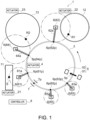
- Fig. 1 is a plan view illustrating a schematic configuration of an analyzer 1 according to a first embodiment of the present disclosure.
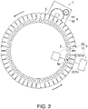
- Fig. 2 is a plan view illustrating a configuration of a cuvette table 3, an actuator 4, and a photometry part 5 which are provided to the analyzer 1 according to the first embodiment of the present disclosure.
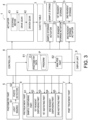
- Fig. 3 is a functional block diagram of the analyzer 1 according to the first embodiment of the present disclosure.
- the analyzer 1 is a device which analyzes reaction liquid of sample S (for example, blood, urine, etc.) and reagent, and may mainly include the cuvette table 3 where a plurality of cuvettes 2 (see Fig. 2 ) are disposed annularly, the actuator 4, the photometry part 5, a pretreatment part 6, a post treatment part 7, and a controller 8.
- sample S for example, blood, urine, etc.
- reagent for example, blood, urine, etc.
- the cuvette table 3 where a plurality of cuvettes 2 (see Fig. 2 ) are disposed annularly, the actuator 4, the photometry part 5, a pretreatment part 6, a post treatment part 7, and a controller 8.
- the cuvette table 3 may be formed annularly in the plan view, and a row of the plurality of cuvettes 2 may be disposed in the annular direction (arc arrow lines in Fig. 2 ).
- the cuvette 2 may be a container which accommodates the sample S and the reagent, and present a rectangular parallelepiped shape (may also be a cube or other shapes) with an upper surface opened, for example.
- the cuvette table 3 may be driven by the actuator 4, and intermittently rotate while alternately repeating a resting state and a rotating state (hereinafter, referred to as "intermittently rotates"), so that the location of the row of cuvettes 2 is displaced in the annular direction (an arc arrow line in Fig.
- the intermittent rotation which is performed in this embodiment may repeat the resting state and the rotating state in the following illustrated mode.
- an angular velocity (rotational speed) of the cuvette table 3 may increase, and it may reach a certain angular velocity.
- the cuvette table 3 may continue the rotation for a given period of time, while maintaining the angular velocity.
- the angular velocity of the cuvette table 3 may be lowered, and the cuvette table 3 may result in the resting state in which it stands still again.
- one intermittent rotation of the cuvette table 3 is referred to as "one sequence.”
- a row of 50 cuvettes 2 may be annularly disposed on the cuvette table 3, and the row of cuvettes 2 may be displaced by 16 (the given number) cuvettes in the annular direction, each time the cuvette table 3 intermittently rotates for one sequence.
- the periphery of the cuvette table 3 (an inner circumferential side and/or an outer circumferential side) may be provided with a sample storage 11 which accommodates a sample container, and a first reagent storage 12 and a second reagent storage 13 which accommodate a first reagent container and a second reagent container, respectively.
- the sample S may be supplied into the cuvette 2 from the sample container at a sample dispensing position 61p (described below), by using a pipette (not illustrated) provided to a sample dispensing part 61 of the pretreatment part 6.
- first reagent R1 may be supplied into the cuvette 2 from the first reagent container at a first reagent dispensing position 62p (described below), by using a pipette (not illustrated) provided to a first reagent dispensing part 62 of the pretreatment part 6, and second reagent R2 may be supplied into the cuvette 2 from the second reagent container at a second reagent dispensing position 64p (described below), by using a pipette (not illustrated) provided to a second reagent dispensing part 64 of the pretreatment part 6.
- the reaction liquid in the cuvette 2 to which the sample S and the first reagent R1 are supplied may be then agitated at a first agitating position 63p (described below), by a first agitating part 63 of the pretreatment part 6, and the reaction liquid in the cuvette 2 to which the sample S, the first reagent R1, and the second reagent R2 are supplied may be then agitated at a second agitating position 65p (described below) by a second agitating part 65 of the pretreatment part 6.
- the second reagent storage 13, a second reagent storage actuator 23, the second reagent dispensing part 64, and the second agitating part 65 may be omitted.
- the actuator 4 may drive the cuvette table 3 so that the cuvette table 3 intermittently rotates, and the position of the row of cuvettes 2 is displaced in the annular direction by the given number of cuvettes, each time the cuvette table 3 intermittently rotates for one sequence.
- the actuator 4 may be controlled by the controller 8.
- the actuator 4 may include, for example, a drive gear 41, and a driven gear 42 connected to the cuvette table 3 and the drive gear 41.
- the drive gear 41 may be attached to a stepping motor 43 (see Fig. 3 ), and by causing the stepping motor 43 to drive and rotating the drive gear 41, the cuvette table 3 can be rotated via the driven gear 42.
- a stepping motor with servo control may be used as the stepping motor 43.
- the photometry part 5 may emit light to each cuvette 2 which passes through a photometric position 5p on the analyzer 1, while the cuvette table 3 intermittently rotates, to measure outgoing light from the illuminated area on the cuvette 2 which passes through the photometric position 5p.
- the photometry part 5 may include a light source 51 provided to the outer circumferential side of the cuvette table 3, and a photo detector 52 provided to the inner circumferential side of the cuvette table 3.
- the light source 51 may be, for example, comprised of a halogen lamp, and emit light toward the photo detector 52. While the cuvette table 3 rotates, the cuvette 2 may cross an optical path of the outgoing light from the light source 51 (a straight arrow line in Fig. 2 ). A position where the optical path of the outgoing light from the light source 51 and the course of the cuvettes 2 cross may be the photometric position 5p.
- the outgoing light from the light source 51 may illuminate the cuvette 2.
- the light which entered into the illuminated area of the cuvette 2 may pass through the inside thereof, and come out from the illuminated area (more accurately, the back side of the illuminated area) of the cuvette 2, and this outgoing light may enter into the photo detector 52.
- the photo detector 52 may photoelectrically convert the outgoing light from the cuvette 2, and output to the controller 8 a voltage signal according to the quantity of light as photometry data D1.
- the pretreatment part 6 may include the sample dispensing part 61, the first reagent dispensing part 62, the first agitating part 63, the second reagent dispensing part 64, and the second agitating part 65.
- the pretreatment part 6 provided with the sample dispensing part 61, the first reagent dispensing part 62, and the first agitating part 63 may be referred to as "the early pretreatment part 6”
- the pretreatment part 6 provided with the second reagent dispensing part 64 and the second agitating part 65 may be referred to as "the later pretreatment part 6," for convenience.
- the sample dispensing part 61, the first reagent dispensing part 62, the first agitating part 63, the second reagent dispensing part 64, and the second agitating part 65 which are provided to the pretreatment part 6 may pretreat the cuvettes 2 located at pretreatment positions 6p (61p-65p) which will be described below, respectively, when the row of cuvettes 2 disposed on the cuvette table 3 is in the resting state.
- the supply of the sample S, the supply of the first reagent R1, the agitation of the reaction liquid in the cuvette 2 to which the first reagent R1 is supplied, the supply of the second reagent R2, and the agitation of the reaction liquid in the cuvette 2 to which the second reagent R2 is supplied may be performed as the pretreatments.
- the pretreatment including the supply of the sample S, the supply of the first reagent R1, and the agitation of the reaction liquid in the cuvette 2 to which the first reagent R1 is supplied may be referred to as "the early pretreatment,” and the supply of the second reagent R2 and the agitation of the reaction liquid in the cuvette 2 to which the second reagent R2 is supplied may be referred to as "the later pretreatment,” for convenience.
- the pretreatment positions 6p may include the sample dispensing position 61p, the first reagent dispensing position 62p, the first agitating position 63p, the second reagent dispensing position 64p, and the second agitating position 65p.
- the pretreatment positions 6p including the sample dispensing position 61p, the first reagent dispensing position 62p, and the first agitating position 63p may be referred to as "the early pretreatment positions 6p”
- the pretreatment positions 6p including the second reagent dispensing position 64p and the second agitating position 65p may be referred to as "the later pretreatment positions 6p," for convenience.
- the sample dispensing part 61 may include an arm 61a and the pipette (not illustrated), and supply the sample S from the sample storage 11 into the cuvette 2 which stands still at the sample dispensing position 61p on the analyzer 1 (perform dispensing processing of the sample S).
- the first reagent dispensing part 62 may include an arm 62a and the pipette (not illustrated), and supply the first reagent R1 from the first reagent storage 12 into the cuvette 2 which stands still at the first reagent dispensing position 62p on the analyzer 1 (perform dispensing processing of the first reagent R1).
- the first agitating part 63 may include an arm 63a and a stirring rod (not illustrated), and agitate the reaction liquid in the cuvette 2 which stands still at the first agitating position 63p (perform agitating processing).
- the second reagent dispensing part 64 may include an arm 64a and the pipette (not illustrated), and supply the second reagent R2 from the second reagent storage 13 into the cuvette 2 which stands still at the second reagent dispensing position 64p on the analyzer 1 (perform dispensing processing of the second reagent R2).
- the second agitating part 65 may include an arm 65a and a stirring rod (not illustrated), and agitate the reaction liquid in the cuvette 2 which stands still at the second agitating position 65p (perform agitating processing).
- the first agitating part 63 and the second agitating part 65 are based on an agitating method using the stirring rods, they may be based on other agitating methods, such as an agitating method using ultrasonic waves, for example, without being limited to the configuration described above.
- the sample dispensing position 61p, the first reagent dispensing position 62p, the first agitating position 63p, the second reagent dispensing position 64p, and the second agitating position 65p may be the above-described pretreatment positions (the early pretreatment positions and the later pretreatment positions) 6p, and mean positions on the analyzer 1 at which processing which is performed before a post treatment, such as washing, is performed. These positions on the analyzer 1 at which each processing is performed may not change, even when the cuvette table 3 intermittently rotates.
- the supply of the sample S, the supply of the first reagent R1, and the agitation of the reaction liquid in the cuvette 2 to which the first reagent R1 is supplied may be performed (i.e., the early pretreatment may be performed), for example, as the pretreatment, and the supply of the second reagent R2 and the agitation of the reaction liquid in the cuvette 2 to which the second reagent R2 is supplied may not be performed (the later pretreatment may not be performed).
- the pretreatment position 6p in this case may include the sample dispensing position 61p, the first reagent dispensing position 62p, and the first agitating position 63p (i.e., include the early pretreatment positions 6p), but may not include the second reagent dispensing position 64p and the second agitating position 65p (may not include the later pretreatment positions 6p).
- the second reagent dispensing part 64 and the second agitating part 65 may be omitted, and the pretreatment (the later pretreatment) may not be performed to the cuvettes 2 which stand still at the second reagent dispensing position 64p and the second agitating position 65p (the later pretreatment positions 6p).
- the post treatment part 7 may carry out the post treatment of the cuvette 2 which stands still at a post treatment position 7p on the analyzer 1, when the row of cuvettes 2 disposed on the cuvette table 3 is in the resting state.
- the post treatment part 7 may be a cuvette washing part 7 which discharges the reaction liquid inside the cuvette 2 and washes the cuvette 2 with given cleaning fluid (performs washing), for example.
- the post treatment position 7p may mean a position on the analyzer 1 at which processing performed after the pretreatment including the sample dispensing etc. is performed.
- the position of the post treatment position 7p may not change, even when the cuvette table 3 intermittently rotates.
- the sample dispensing part 61, the first reagent dispensing part 62, the first agitating part 63, the second reagent dispensing part 64, and the second agitating part 65 of the pretreatment part 6, and the post treatment part 7 each may be provided with two sets of processing units (hereinafter, referred to as "a-system” and "b-system”). That is, as illustrated in the schematic diagrams of Figs.
- the sample dispensing part 61 may be provided with the two sets of processing units which are the a-system and the b-system (hereinafter, in order to distinguish one from the other, may also be represented by reference characters "Sa" and "Sb"), and the two sets of sample dispensing parts Sa and Sb may dispense the sample S into two cuvettes 2 which are located adjacent to each other at the sample dispensing position 61p.
- the sample dispensing position 61p may mean the positions of the two adjacent cuvettes, for example, which are enclosed by a box in Fig.
- the positions of these two adjacent cuvettes may be distinguishably referred to as "the first sample dispensing position 61p" and “the second sample dispensing position 61p,” respectively. Similar things may be said about the first reagent dispensing part 62 (hereinafter, also represented by reference characters “R1a” and “R1b”), the first agitating part 63 (hereinafter, also represented by reference characters “M1a” and “M1b"), the second reagent dispensing part 64 (hereinafter, also represented by reference characters “R2a” and “R2b"), the second agitating part 65 (hereinafter, also represented by reference characters “M2a” and “M2b”), and the post treatment part 7 (hereinafter, also represented by reference characters "Wa” and “Wb”), and similar things may be said to the first reagent dispensing position 62p, the first agitating position 63p, the second reagent dispensing position 64p, the second agitating position 65p, and similar things
- a processing unit belonging to the a-system may perform processing to other processing unit belonging to the a-system
- a processing unit belonging to the b-system may perform processing to other processing unit belonging to the b-system.
- the sample dispensing part Sa may dispense the sample into the cuvette 2
- the first reagent dispensing part R1a may dispense the reagent R1 into the cuvette 2
- the first agitating part M1a may agitate.
- the cuvette washing part Wa may wash the cuvette 2.
- the component(s) in the sample is analyzed using one kind of reagent (the first reagent R1)
- the second reagent dispensing parts 64 (R2a, R2b) and the second agitating parts 65 (M2a, M2b) which have the respective two systems
- the a-system and the b-system may be omitted. That is, the later pretreatment of each system may be omitted.
- the controller 8 may be an information processor which controls various operations of the analyzer 1.
- the controller 8 may include a memory 81 and an analysis part 82.
- the memory 81 may be a configuration of hardware, and the analysis part 82 may be a functional block by software.
- a control by the controller 8 including processing by the analysis part 82 may be implemented by executing a computer program P stored in the memory 81.
- the controller 8 may further be provided with a processor, such as a CPU, which performs data processing, as a configuration of the hardware.
- the controller 8 may operate the actuator 4, and a sample storage actuator 21, a first reagent storage actuator 22, and the second reagent storage actuator 23, which will be described later, so as to synchronize the actuator 4 with the actuators. Further, the controller 8 may control operation of the photometry part 5, the pretreatment part 6, and the post treatment part 7 according to the intermittent rotation of the cuvette table 3 through the actuator 4.
- the photometry part 5 may be activated when the cuvette table 3 is in the rotating state (including a speed changing state, such as an accelerating state and a decelerating state), and the pretreatment part 6 and the post treatment part 7 may be activated when the cuvette table 3 is in the resting state.
- the controller 8 may perform, in the rotating state until the cuvette which stood still at the pretreatment position 6p stands still at the post treatment position 7p after the completion of the pretreatment, a control for causing the actuator to make the cuvette pass through the photometric position 5p at a fixed rotational speed, each time the cuvette passes through the photometric position 5p.
- the controller 8 may rotate the cuvette table 3 for about three seconds, and maintain the resting state for about seven seconds. That is, the controller 8 may perform the one-sequence intermittent rotation of the cuvette table 3, every about 30 seconds.
- the memory 81 may store the computer program P which performs the control by the controller 8, various data which is used by the controller 8, etc.
- the memory 81 may be comprised of a volatile memory such as a DRAM, or a nonvolatile memory such as a flash memory, or a combination of both.
- the analysis part 82 may analyze the component(s) in the sample S based on the photometry data D1.
- the analysis of the component(s) may be performed to each of the photometry data for the first-step reaction liquid of the sample S and the first reagent R1, and the photometry data for the second-step reaction liquid which is prepared by further dispensing the second reagent R2 to the first-step reaction liquid.
- the analysis result by the analysis part 82 may be displayed on a display unit 9.
- the sample storage 11 may be conveying equipment (a conveying line) which sequentially conveys a plurality of samples S, and may be driven by the controller 8 via the sample storage actuator 21.
- the first reagent storage 12 may be formed annularly in the plan view, where a plurality of first reagent containers, each containing the first reagent R1, are disposed in the annular direction.
- the first reagent storage 12 may be rotated by the controller 8 via the first reagent storage actuator 22.
- the second reagent storage 13 may be formed annularly in the plan view, where a plurality of second reagent containers, each containing the second reagent R2, are disposed in the annular direction.
- the second reagent storage 13 may be rotated by the controller 8 via the second reagent storage actuator 23.
- Fig. 4 is a flowchart illustrating the analysis process which the analyzer 1 according to the first embodiment of the present disclosure performs to the row of cuvettes 2.
- the control may be performed so that the cuvette table 3 where the plurality of cuvettes 2 are disposed annularly is driven so that the cuvette table 3 carries out the intermittent rotation in which the resting state and the rotating state are repeatedly alternated, and each time the cuvette table 3 rotates intermittently, the row of the plurality of cuvettes 2 is displaced in the annular direction by the given number of cuvettes (Step S1).
- the pretreatment may be performed to the cuvette 2 among the plurality of cuvettes 2 which stands still at the pretreatment position 6p (Step S2).
- the post treatment may be performed to the cuvette 2 among the plurality of cuvettes 2 which stands still at the post treatment position 7p (Step S3).
- the photometry may be performed to the cuvette 2 which passes through the photometric position 5p, and in the rotating state until the cuvette 2 which stood still at the pretreatment position 6p stands still at the post treatment position 7p after the completion of the pretreatment, the cuvette 2 may be caused to pass through the photometric position 5p at the fixed rotational speed, each time it passes through the photometric position 5p (Step S4).
- the computer program P stored in the controller 8 may cause the computer to realize a control function in which the cuvette table 3 where the plurality of cuvettes 2 are disposed annularly is driven so that the cuvette table 3 carries out the intermittent rotation in which the resting state and the rotating state are repeatedly alternated, and each time the cuvette table 3 rotates intermittently, the row of the plurality of cuvettes 2 is displaced in the annular direction by the given number of cuvettes, a control function in which, in the resting state, the pretreatment is performed to the cuvette 2 among the plurality of cuvettes 2 which stands still at the pretreatment position 6p, a control function in which, in the resting state, the post treatment is performed to the cuvette 2 among the plurality of cuvettes 2 which stands still at the post treatment position 7p, a control function in which, in the rotating state, the photometry is performed to the cuvette 2 which passes through the photometric position 5p, and a control function in which, in
- each part of the pretreatment part 6 and the post treatment part 7 each may be provided with the two sets of processing units, the a-system and the b-system.
- the sample dispensing part Sa (first pretreatment part) of the a-system may perform the processing to the cuvette 2 which stands still at the first sample dispensing position 61p
- the sample dispensing part Sb (second pretreatment part) of the b-system may perform the processing to the cuvette 2 which stands still at the second sample dispensing position 61p.
- the first reagent dispensing part R1a (first pretreatment part) of the a-system may perform the processing to the cuvette 2 which stands still at the first first reagent dispensing position 62p
- the first reagent dispensing part R1b (second pretreatment part) of the b-system may perform the processing to the cuvette 2 which stands still at the second first reagent dispensing position 62p.
- the first agitating part M1a (first pretreatment part) of the a-system may perform the processing to the cuvette 2 which stands still at the first first agitating position 63p
- the first agitating part M1b (second pretreatment part) of the b-system may perform the processing to the cuvette 2 which stands still at the second first agitating position 63p
- the second reagent dispensing part R2a (first pretreatment part) of the a-system may perform the processing to the cuvette 2 which stands still at the first second reagent dispensing position 64p
- the second reagent dispensing part R2b (second pretreatment part) of the b-system may perform the processing to the cuvette 2 which stands still at the second second reagent dispensing position 64p.
- the second agitating part M2a (first pretreatment part) of the a-system may perform the processing to the cuvette 2 which stands still at the first second agitating position 65p
- the second agitating part M2b (second pretreatment part) of the b-system may perform the processing to the cuvette 2 which stands still at the second second agitating position 65p.
- the first pretreatment and the second pretreatment including the sample dispensing by the sample dispensing parts Sa and Sb, the first reagent dispensing by the first reagent dispensing parts R1a and R1b, the first agitating by the first agitating parts R1a and R1b of the systems may be referred to as "the first early pretreatment” and "the second early pretreatment,” respectively, for convenience.
- first pretreatment and the second pretreatment including the second reagent dispensing by the second reagent dispensing parts R2a and R2b, and the second agitating by the second agitating parts M2a and M2b may be referred to as "the first later pretreatment” and "the second later pretreatment,” respectively.
- the post treatment part Wa (first post treatment part) of the a-system may perform the processing to the cuvette 2 which stands still at the first post treatment position 7p
- the post treatment part Wb (second post treatment part) of the b-system may perform the processing to the cuvette 2 which stands still at the second post treatment position 7p.
- the sample dispensing part Sa, the first reagent dispensing part R1a, the first agitating part M1a, the second reagent dispensing part R2a, and the second agitating part M2a, which pretreat the a-system, may be referred to as "the first pretreatment part,” and the sample dispensing part Sb, the first reagent dispensing part R1b, the first agitating part M1b, the second reagent dispensing part R2b, and the second agitating part M2b, which pretreat the b-system, may be referred to as "the second pretreatment part.”
- the first pretreatment part and the second pretreatment part having the sample dispensing parts Sa and Sb, the first reagent dispensing parts R1a and R1b, and the first agitating parts M1a and M1b of the systems may be referred to as "the first pretreatment part and the second pretreatment part having the sample dispensing parts Sa and Sb, the first reagent dispens
- first pretreatment part and the second pretreatment part having the second reagent dispensing parts R2a and R2b, and the second agitating parts M2a and M2b of the systems may be referred to as “the first later pretreatment part” and “the second later pretreatment part,” respectively.
- the first sample dispensing position 61p, the first first reagent dispensing position 62p, the first first agitating position 63p, the first second reagent dispensing position 64p, and the first second agitating position 65p, where the pretreatments of the a-system are performed may be referred to as "the first pretreatment positions," and the second sample dispensing position 61p, the second first reagent dispensing position 62p, the second first agitating position 63p, the second second reagent dispensing position 64p, and the second second agitating position 65p, where the pretreatments of the b-system are performed, may be referred to as "the second pretreatment positions.”
- the first pretreatment position and the second pretreatment position including the first sample dispensing position 61p and the second sample dispensing position 61p, the first first reagent dispensing position 62p and
- first pretreatment position and the second pretreatment position including the first second reagent dispensing position 64p and the second second reagent dispensing position 64p, and the first second agitating position 65p and the second second agitating position 65p may be referred to as "the first later pretreatment position” and "the second later pretreatment position,” respectively.
- Table 1 is a table illustrating in detail the analysis process which the analyzer 1 according to the first embodiment of the present disclosure performs to the row of cuvettes 2.
- Table 1 operation which each of the photometry part 5, the pretreatment part 6, and the post treatment part 7 performs to the cuvette 2 is illustrated for every intermittent rotation of the cuvette table 3 (see each line of Table 1).
- Figs. 5 to 11 are schematic diagrams illustrating relationships between the intermittent rotating operation of the cuvette table 3 illustrated in Table 1, and the operation which each of the photometry part 5, the pretreatment part 6, and the post treatment part 7 performs to the cuvette 2.
- the photometry position 5p the pretreatment positions 6p (the sample dispensing position 61p, the first reagent dispensing position 62p, the first agitating position 63p, the second reagent dispensing position 64p, and the second agitating position 65p), and the post treatment position 7p on the analyzer 1 may be fixed.
- the given number of cuvettes located in the positive rotational direction (the direction of the arc arrow line in Fig. 5 ) from the photometric position 5p may be cuvettes which passed through the photometric position 5p, while the cuvettes being decelerated immediately before being in the resting state, and, for example, the given number of cuvettes located in the negative rotational direction from the photometric position 5p may be cuvettes which pass through the photometric position 5p, while the cuvettes being accelerated when starting the next sequence operation immediately after the resting state.
- one cuvette 2 located in the positive rotational direction from the photometric position 5p may pass through the photometric position 5p, while the cuvette being decelerated, and one cuvette 2 located in the negative rotational direction (the opposite direction from the arc arrow line in Fig. 5 ) from the photometric position 5p may pass through the photometric position 5p, while the cuvette being accelerated.
- the first and second cuvettes located at the leading end of the row which are displayed by a black and white reversal in Table 1 and Figs. 5 to 110 (hereinafter, "cuvettes of interest") are mainly described.
- the cuvettes of interest may pass through the photometric position 5p at the fixed rotational speed, each time they pass through the photometric position 5p.
- Fig. 5 illustrates an initial layout of the row of cuvettes 2 before the cuvette table 3 rotates intermittently.
- the first reagent R1 may be dispensed into the cuvettes of interest at the first reagent dispensing position 62p by the first reagent dispensing parts 62 (R1a, R1b).
- the 31st and 32nd cuvettes may be washed by the cuvette washing parts 7 (Wa, Wb) at the post treatment position 7p.
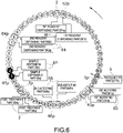
- Fig. 6 illustrates the layout of the row of cuvettes 2 after the cuvette table 3 has operated for one sequence (moved by 16 cuvettes).
- the sample S may be dispensed into the cuvettes of interest at the sample dispensing position 61p by the sample dispensing parts 61 (Sa, Sb).
- the first reagent dispensing parts 62 (R1a, R1b) which dispensed the first reagent R1 into the cuvettes of interest in the previous sequence may dispense the first reagent R1 into the 17th and 18th cuvettes in this sequence.
- the 31st cuvette located in the positive rotational direction from the photometric position 5p may be a cuvette which passed through the photometric position 5p, while the cuvette being decelerated, and the 33rd cuvette located in the negative rotational direction from the photometric position 5p may be a cuvette which passes through the photometric position 5p, while the cuvette being accelerated during the next sequence operation.
- the 32nd cuvette may be a cuvette located at the photometric position 5p in the resting state.
- These 31st to 33rd cuvettes may be non-prepared cuvettes which are not prepared for performing the first-step photometry, which will be described later.
- the 47th and 48th cuvettes may be washed by the cuvette washing parts 7 (Wa, Wb) at the post treatment position 7p.
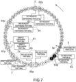
- Fig. 7 illustrates the layout of the row of cuvettes 2 after the cuvette table 3 has operated for two sequences (moved by 32 cuvettes).
- the first reagent R1 and the sample S in the cuvettes of interest may be agitated to prepare the first-step reaction liquid by the first agitating parts 63 (M1a, M1b) at the first agitating position 63p.
- the pretreatment for the first-step photometry may be completed.
- the photometry first-step photometry
- the photometry may be performed as the cuvettes of interest pass through the photometric position 5p during the subsequent sequence operations.
- the 47th cuvette located in the positive rotational direction from the photometric position 5p may be a cuvette which passed through the photometric position 5p, while the cuvette being decelerated, and the 49th cuvette located in the negative rotational direction from the photometric position 5p may be a cuvette which passes through the photometric position 5p, while the cuvette being accelerated during the next sequence operation.
- the 48th cuvette may be a cuvette located at the photometric position 5p in the resting state.
- These 47th to 49th cuvettes may be also non-prepared cuvettes which are not prepared for performing the first-step photometry (described later).
- Fig. 8 illustrates the layout of the row of cuvettes 2 after the cuvette table 3 has operated for three sequences (moved by 48 cuvettes).
- the photometry data D1 may have been acquired by the photometry part 5 (DTR), by the cuvettes of interest passing through the photometric position 5p at the fixed speed.
- the pretreatment for the first-step photometry may have been completed. Therefore, the photometry data D1 of the cuvettes of interest acquired during this sequence operation may be photometry data which is not influenced by the inertia caused during the acceleration or the deceleration of the cuvette table 3.
- the sequence in which the cuvette table 3 rotates intermittently may be repeated and the first-step photometry may be performed to the cuvettes of interest to acquire the photometry data D1 each of during the sixth sequence operation and during the ninth sequence operation.
- the photometry data D1 of the cuvettes of interest acquired in these sequences may also be the photometry data which is not influenced by the inertia caused during the acceleration or the deceleration of the cuvette table 3.
- the second reagent R2 may be dispensed into the cuvettes of interest at the second reagent dispensing position 64p by the second reagent distributive pouring parts 64 (R2a, R2b).
- the first-step reaction liquid and the second reagent in the cuvettes of interest may be agitated to prepare the second-step reaction liquid at the second agitating position 65p by the second agitating parts 65 (M2a, M2b).
- the pretreatment for the second-step photometry may be completed.
- the photometry (second-step photometry) may be performed by the cuvettes of interest passing through the photometric position 5p during the subsequent sequence operations.
- the sequence in which the cuvette table 3 rotates intermittently may be repeated, and the second-step photometry may be performed to the cuvettes of interest to acquire the photometry data D1 each of during the 12th sequence operation, during the 15th sequence operation, and during the 18th sequence operation.
- Fig. 9 illustrates the layout of the row of cuvettes 2 after the cuvette table 3 has operated for 20 sequences (moved by 320 cuvettes).
- the reaction liquid second-step reaction liquid
- the cuvettes of interest may be washed with the given cleaning fluid at the post treatment position 7p by the cuvette washing parts 7 (Wa, Wb).
- the cuvettes of interest may stand still neither at the photometric position 5p, nor at the position where the photometry is performed while the cuvette of interest being decelerated, nor at the position where the photometry is performed while the cuvette of interest being accelerated, until after the 20th sequence operation when the post treatment is completed. That is, in the rotating state until the cuvettes of interest which stood still at the pretreatment position 6p stand still at the post treatment position 7p after the completion of the pretreatment, the cuvettes of interest may pass through the photometric position 5p at the fixed rotational speed, each time the cuvettes of interest pass through the photometric position 5p.
- both the first and second cuvettes which are the cuvettes of interest may pass through the photometric position 5p at the fixed speed, when the cuvette table 3 is in the rotating state until after the 20th sequence operation when the post treatment is completed.
- the first cuvette and the second cuvette may stand still at the post treatment position 7p after the 20th sequence operation.
- both the first cuvette and the second cuvette may pass through the photometric position 5p at the fixed rotational speed (i.e., both the cuvettes may pass through the photometric position 5p at the fixed rotational speed during the same sequence), each time the cuvettes pass through the photometric position 5p substantially simultaneously.
- first post treatment position and the second post treatment position may correspond to positions of the cuvettes 2 for which the processing is performed by the two sets of processing units (i.e., the post treatment part Wa and the post treatment part Wb) among the post treatment positions 7p for the two cuvettes which are surrounded by the box in Fig. 9 , respectively.
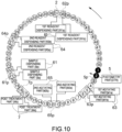
- Fig. 10 illustrates the layout of the row of cuvettes 2 after the cuvette table 3 has operated for 21 sequences (moved by 336 cuvettes).
- the first cuvette may pass through the photometric position 5p, while the cuvette being decelerated.
- the photometry data D1 of this first cuvette may be influenced by the inertia caused during the deceleration of the cuvette table 3. Further, the second cuvette may stand still at the photometric position 5p in the resting state.
- these two cuvettes of interest may have already been post-treated after the previous 20th sequence operation, and may be cuvettes without the necessity of the photometry in the first place. Further, for these two cuvettes of interest, the first-step photometry and the second-step photometry may have already been completed in a state where they are not influenced by the inertia caused during the acceleration or the deceleration of the cuvette table 3. Therefore, the photometry data acquired for the cuvettes of interest during this sequence operation may be photometry data which does not need to be used for the analysis by the analysis part 82 in the first place, and it can be excluded from the analysis.
- Fig. 11 illustrates the layout of the row of cuvettes 2 after the cuvette table 3 has operated for 25 sequences (moved by 400 cuvettes).
- the first reagent R1 may be dispensed into the cuvettes of interest at the first reagent dispensing position 62p by the first reagent dispensing parts 62 (R1a, R1b).
- the controller 8 may intermittently rotate the cuvette table 3 so that the cuvette after the post treatment for which the photometry does not need to be performed stands still at any of the photometric position 5p, the position where the photometry is performed while the cuvette being decelerated, and the position where the photometry is performed while the cuvette being accelerated.
- the photometry position 5p, the pretreatment positions 6p (the sample dispensing position 61p, the first reagent dispensing position 62p, the first agitating position 63p, the second reagent dispensing position 64p, and the second agitating position 65p), and the post treatment position 7p on the analyzer 1 may also be disposed so as to realize the above configuration.
- the cuvette 2 which stood still at the post treatment position 7p after the previous sequence operation may stand still at the photometric position 5p after one sequence operation. That is, the controller 8 may cause the cuvette which stood still at the post treatment position 7p to stand still at the photometric position 5p after at least one intermittent rotating operation.
- the cuvette of interest (the second cuvette) which stands still at the photometric position 5p after the 21st sequence operation may stand still at the post treatment position 7p after the 20th sequence operation.
- a specific number of cuvettes 2 which are adjacent to each other forward and backward in the annular direction, including the cuvette 2 concerned, may pass through the photometric position 5p at the fixed rotational speed.
- the specific number of cuvettes 2 may be a number obtained by subtracting the number of cuvettes 2 which stand still at the photometric position 5p in the resting state and the number of cuvettes 2 which pass through the photometric position 5p in the rotating state during the acceleration or the deceleration of the rotation of the cuvette table 3, from the given number of cuvettes 2 (in this embodiment, 16 cuvettes).
- the state from after the second sequence operation to after the third sequence operation when the cuvettes of interest pass through the photometric position 5p at the fixed speed for the first time, as illustrated in Table 1, is described.
- the given number of cuvettes 2 which rotate by one intermittent rotation may be 16.
- the number of cuvettes 2 which stand still at the photometric position 5p in the resting state may be one
- the number of cuvettes 2 which pass through the photometric position 5p in the rotating state during the acceleration or the deceleration of the rotation of the cuvette table 3 may be one for each case.
- the specific number of cuvettes 2 in this case, 13 cuvettes which are adjacent to each other forward and backward in the annular direction, including the cuvette 2 concerned, may pass through the photometric position 5p at the fixed rotational speed.
- the total of 13 cuvettes from the 50th cuvette to the 12th cuvettes which are adjacent to each other forward and backward, including the first cuvette which is the cuvette of interest may pass through the photometric position 5p at the fixed rotational speed after the third sequence operation.
- the analyzer 1 can reduce the adverse effect to the photometry due to the inertia caused by the speed change during the acceleration or the deceleration of the cuvette table 3, and can automatically analyze the plurality of samples S.
- the photometry data excluded from the analysis may be the photometry data of the cuvette without the necessity of the photometry in the first place, and the accuracy of the analytical value calculated based on the photometry data will not fall.
- the analyzer 1 since the photometry data of the cuvette without the necessity of the photometry in the first place is excluded from the analysis, the accuracy of the analytical value calculated based on the photometry data will not fall.
- the size of the analyzer including the cuvette table is enlarged. This is because it is necessary to extend the circumference length of the cuvette table by the moving distance of the cuvette which passed through the photometric position on the analyzer at the above-described timing where the illuminated area on the cuvette is deviated.
- the size of the analyzer can be reduced, without enlarging the size of the analyzer.
- the controller 8 may intermittently rotate the cuvette table 3 so that the cuvette without the necessity of performing the photometry after the post treatment of the cuvette stands still at any of the photometric position 5p, the position where the photometry is performed while the cuvette being decelerated, and the position where the photometry is performed while the cuvette being accelerated.
- the controller 8 may intermittently rotate the cuvette table 3 so that the non-prepared cuvette which is not prepared for performing the first-step photometry stands still at any of the photometric position 5p, the position where the photometry is performed while the cuvette being decelerated, and the position where the photometry is performed while the cuvette being accelerated.
- the controller 8 may cause the cuvette to stand still at the photometric position 5p until the pretreatment of the cuvette is completed.
- Table 2 is a table illustrating the analysis process which the analyzer 1 according to the second embodiment of the present disclosure performs to the row of cuvettes 2.
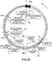
- Figs. 12 to 20 are schematic diagrams illustrating in detail relationships between intermittent rotating operation of the cuvette table 3 illustrated in Table 2 and operation which each of the photometry part 5, the pretreatment part 6, and the post treatment part 7 performs to the cuvette 2.
- the layout of the photometric position 5p and the first agitating position 63p may be changed from the layout of the first embodiment.
- Fig. 12 illustrates the initial layout of the row of cuvettes 2 before the cuvette table 3 rotates intermittently.
- the first reagent R1 may be dispensed into the cuvettes of interest at the first reagent dispensing position 62p by the first reagent dispensing parts 62 (R1a, R1b).
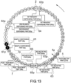
- Fig. 13 illustrates the layout of the row of cuvettes 2 after the cuvette table 3 has operated for one sequence (moved by 16 cuvettes).
- the sample S may be dispensed into the cuvettes of interest at the sample dispensing position 61p by the sample dispensing parts 61 (Sa, Sb).
- Fig. 14 illustrates the layout of the row of cuvettes 2 after the cuvette table 3 has operated for two sequences (moved by 32 cuvettes).
- the cuvettes may have not yet been located at the first agitating position 63p, and therefore, they may have not yet been agitated by the first agitating parts 63 (M1a, M1b). That is, the cuvettes of interest may be both non-prepared cuvettes which are not prepared for performing the first-step photometry.
- the first cuvette may stand still at the photometric position 5p in the resting state.
- the second cuvette may pass through the photometric position 5p, while being accelerated, during the next sequence operation. That is, both the cuvettes of interest may stand still at any of the photometric position 5p, the position where the photometry is performed while the cuvette being decelerated, and the position where the photometry is performed while the cuvette being accelerated.
- the controller 8 may intermittently rotate the cuvette table 3 so that the non-prepared cuvette which is not prepared for performing the first-step photometry stands still at any of the photometric position 5p, the position where the photometry is performed while the cuvette being decelerated, and the position where the photometry is performed while the cuvette being accelerated.
- the controller 8 may cause the cuvette to stand still at the photometric position 5p until the pretreatment of the cuvette is completed.
- Fig. 15 illustrates the layout of the row of cuvettes 2 after the cuvette table 3 has operated for three sequences (moved by 48 cuvettes).
- the photometry data D1 may have been acquired by the photometry part 5 (DTR) as the cuvette passes through the photometric position 5p while being accelerated.
- the photometry data D1 for the second cuvette may be influenced by the inertia caused during the acceleration of the cuvette table 3.
- this second cuvette may be a non-prepared cuvette for which the pretreatment for the first-step photometry has not been completed. Therefore, the photometry data acquired for the second cuvette during this sequence operation may be photometry data which does not need to be used for the analysis by the analysis part 82 in the first place, and it can be excluded from the analysis.
- Fig. 165 illustrates the layout of the row of cuvettes 2 after the cuvette table 3 has operated for five sequences (moved by 80 cuvettes).
- the first reagent R1 and the sample S in the cuvettes of interest may be agitated to prepare the first-step reaction liquid by the first agitating parts 63 (M1a, M1b) at the first agitating position 63p.
- the pretreatment for the first-step photometry may be completed.
- the photometry first-step photometry
- the photometry may be performed as the cuvettes pass through the photometric position 5p during the subsequent sequence operations.
- Fig. 17 illustrates the layout of the row of cuvettes 2 after the cuvette table 3 has operated for six sequences (moved by 96 cuvettes).
- the photometry data D1 may have been acquired by the photometry part 5 (DTR), as the cuvettes pass through the photometric position 5p at the fixed speed.
- the pretreatment for the first-step photometry may have been completed. Therefore, the photometry data D1 of the cuvettes of interest acquired during this sequence operation may be photometry data which is not influenced by the inertia caused during the acceleration or the deceleration of the cuvette table 3.
- the sequence in which the cuvette table 3 rotates intermittently may be repeated, and during the 9th sequence operation, the first-step photometry may be performed to the cuvettes of interest to acquire the photometry data D1.
- the photometry data D1 of the cuvettes of interest acquired by this sequence may also be photometry data which is not influenced by the inertia caused during the acceleration or the deceleration of the cuvette table 3.
- the sequence in which the cuvette table 3 rotates intermittently may be repeated, and the pretreatment for the second-step photometry may be completed to the cuvettes of interest, and the second-step photometry may be performed to the cuvettes of interest to acquire the photometry data D1.
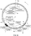
- Fig. 18 illustrates the layout of the row of cuvettes 2 after the cuvette table 3 has operated for 20 sequences (moved by 320 cuvettes).
- the reaction liquid (the second-step reaction liquid) may be discharged and the cuvettes may be washed with given cleaning fluid at the post treatment position 7p by the cuvette washing parts 7 (Wa, Wb).
- the cuvettes of interest may not stand still at any of the photometric position 5p, the position where the photometry is performed while the cuvette being decelerated, and the position where the photometry is performed while the cuvette being accelerated, until after the 20th sequence operation when the post treatment is completed after the fifth sequence operation when the pretreatment is completed. That is, after the fifth sequence operation when the pretreatment is completed, the cuvettes of interest may pass through the photometric position 5p at the fixed rotational speed, each time the cuvettes pass through the photometric position 5p, in the rotating state until the cuvettes of interest which stood still at the pretreatment position 6p stand still at the post treatment position 7p after the completion of the pretreatment.
- both the first and second cuvettes which are the cuvettes of interest may pass through the photometric position 5p at the fixed speed, when the cuvette table 3 is in the rotating state, until after the 20th sequence operation when the post treatment is completed.
- the first cuvette and the second cuvette may stand still at the post treatment position 7p after the 20th sequence operation.
- both the first cuvette and the second cuvette may pass through the photometric position 5p at the fixed rotational speed, each time the cuvettes pass through the photometric position 5p substantially simultaneously (i.e., both the cuvettes may pass through the photometric position 5p at the fixed rotational speed during the same sequence).
- first post treatment position and the second post treatment position may correspond to the positions of the cuvettes 2 for which the processing is performed by the two sets of processing units (i.e., the post treatment part Wa and the post treatment part Wb) among the post treatment positions 7p for the two cuvettes which are surrounded by the box in Fig. 18 , respectively.
- Fig. 19 illustrates the layout of the row of cuvettes 2 after the cuvette table 3 has operated for 21 sequences (moved by 336 cuvettes).
- the photometry data D1 may have been acquired by the photometry part 5 (DTR) as the cuvettes pass through the photometric position 5p at the fixed speed.
- the post treatment may have already been performed after the previous 20th sequence operation, and they may be cuvettes without the necessity of the photometry in the first place.
- the first-step photometry and the second-step photometry may have already been completed in the state where they are not influenced by the inertia caused during the acceleration or the deceleration of the cuvette table 3. Therefore, the photometry data acquired for the cuvettes of interest during this sequence operation may be photometry data which does not need to be used for the analysis by the analysis part 82 in the first place, and it can be excluded from the analysis.
- Fig. 20 illustrates the layout of the row of cuvettes 2 after the cuvette table 3 has operated for 25 sequences (moved by 400 cuvettes).
- the first reagent R1 may be dispensed into the cuvettes of interest at the first reagent dispensing position 62p by the first reagent dispensing parts 62 (R1a, R1b).
- the pretreatment for the first-step photometry may be completed after the fifth sequence operation.
- the controller 8 may intermittently rotate the cuvette table 3 so that the non-prepared cuvette which is not prepared for performing the first-step photometry stands still at any of the photometric position 5p, the position where the photometry is performed while the cuvette being decelerated, and the position where the photometry is performed while the cuvette being accelerated, until the preparation for performing the first-step photometry is completed.
- the controller 8 may cause the cuvette to stand still at the photometric position 5p until the pretreatment of the cuvette is completed.
- the photometry position 5p, the pretreatment positions 6p (the sample dispensing position 61p, the first reagent dispensing position 62p, the first agitating position 63p, the second reagent dispensing position 64p, and the second agitating position 65p), and the post treatment position 7p on the analyzer 1 may also be disposed so as to realize the above configuration.
- the cuvette 2 which stood still at the post treatment position 7p after the previous sequence operation may stand still at the photometric position 5p after a plurality of sequence operations. That is, the controller 8 may cause the cuvette which stood still at the post treatment position 7p to stand still at the photometric position 5p after at least one intermittent rotating operation.
- the cuvette of interest (the second cuvette) which stands still at the position where the photometry is performed while the cuvette being decelerated after the 24th sequence operation may be located at the post treatment position 7p after the 20th sequence operation.
- the plurality of samples S can be automatically analyzed, while reducing the adverse effect to the photometry due to the inertia caused during the acceleration or the deceleration of the cuvette table 3.
- the photometry data excluded from the analysis may be photometry data of the cuvette without the necessity of the photometry in the first place, and the accuracy of the analytical value calculated based on the photometry data will not fall.
- the post treatment part 7 is the cuvette washing part
- the post treatment part 7 may be a cuvette disposal part which disposes the cuvette 2 which stands still at the post treatment position 7p on the analyzer 1 (performs disposal processing).
- each of the pretreatment part 6 and the post treatment part 7 are each provided with the two sets of processing units, each of the pretreatment part 6 and the post treatment part 7 may be comprised of a single processing unit, or may be comprised of three or more processing units.
- the components in the sample are analyzed using the two kinds of reagents to the same sample
- the components to be analyzed are not limited to two kinds.
- the analysis may be performed only using the first reagent R1 without using the second reagent R2 (i.e., the component in the sample may be analyzed using one kind of reagent).
- the components in the sample may be analyzed using three or more kinds of reagents to the same sample.
- the controller 8 is provided to the analyzer 1, the controller 8 does not need to be directly provided to the analyzer 1, and it may be configured as a controller on a cloud network, which is connected to the analyzer 1.
- the phrase "the controller 8 is provided to the analyzer 1" may mean both a mode in which the controller 8 is provided directly to the analyzer 1 and a mode in which the controller 8 on the cloud network is provided.
Landscapes
- Chemical & Material Sciences (AREA)
- Physics & Mathematics (AREA)
- Health & Medical Sciences (AREA)
- Life Sciences & Earth Sciences (AREA)
- Analytical Chemistry (AREA)
- Biochemistry (AREA)
- General Health & Medical Sciences (AREA)
- General Physics & Mathematics (AREA)
- Immunology (AREA)
- Pathology (AREA)
- Chemical Kinetics & Catalysis (AREA)
- Automatic Analysis And Handling Materials Therefor (AREA)
Applications Claiming Priority (2)
| Application Number | Priority Date | Filing Date | Title |
|---|---|---|---|
| JP2020083741 | 2020-05-12 | ||
| PCT/JP2021/015134 WO2021229970A1 (ja) | 2020-05-12 | 2021-04-12 | 分析装置、分析方法、およびプログラム |
Publications (2)
| Publication Number | Publication Date |
|---|---|
| EP4152007A1 true EP4152007A1 (de) | 2023-03-22 |
| EP4152007A4 EP4152007A4 (de) | 2024-06-19 |
Family
ID=78476914
Family Applications (1)
| Application Number | Title | Priority Date | Filing Date |
|---|---|---|---|
| EP21803159.9A Withdrawn EP4152007A4 (de) | 2020-05-12 | 2021-04-12 | Analysevorrichtung, analyseverfahren und programm |
Country Status (5)
| Country | Link |
|---|---|
| US (1) | US20230084681A1 (de) |
| EP (1) | EP4152007A4 (de) |
| JP (1) | JPWO2021229970A1 (de) |
| CN (1) | CN113654988A (de) |
| WO (1) | WO2021229970A1 (de) |
Families Citing this family (1)
| Publication number | Priority date | Publication date | Assignee | Title |
|---|---|---|---|---|
| CN120344859A (zh) * | 2023-02-02 | 2025-07-18 | 株式会社日立高新技术 | 自动分析装置 |
Family Cites Families (8)
| Publication number | Priority date | Publication date | Assignee | Title |
|---|---|---|---|---|
| GB1582434A (en) * | 1976-05-13 | 1981-01-07 | Secr Social Service Brit | Analytical apparatus and methods incorporating cuvette cleaning and cleanliness testing |
| JPH08304413A (ja) | 1995-04-28 | 1996-11-22 | Hitachi Ltd | 自動分析装置 |
| CN101419240B (zh) * | 2007-10-23 | 2013-07-17 | 深圳迈瑞生物医疗电子股份有限公司 | 样本分析装置和样本分析方法 |
| JP2009281941A (ja) * | 2008-05-23 | 2009-12-03 | Olympus Corp | 分析方法及び分析装置 |
| JP5063623B2 (ja) * | 2009-01-30 | 2012-10-31 | 株式会社日立ハイテクノロジーズ | 分析装置、及び円盤ディスクの回転制御方法 |
| JP5953089B2 (ja) * | 2012-03-30 | 2016-07-13 | 株式会社Lsiメディエンス | 測定データの異常を検出する方法、及び、測定データの異常検出装置 |
| US10094842B2 (en) * | 2014-10-17 | 2018-10-09 | Shenzhen Mindray Bio-Medical Electronics Co., Ltd. | Automatic biochemical analyzer |
| JP6972946B2 (ja) * | 2017-11-10 | 2021-11-24 | 株式会社Jvcケンウッド | 分析装置及び分析方法 |
-
2021
- 2021-04-12 WO PCT/JP2021/015134 patent/WO2021229970A1/ja not_active Ceased
- 2021-04-12 JP JP2022522565A patent/JPWO2021229970A1/ja active Pending
- 2021-04-12 EP EP21803159.9A patent/EP4152007A4/de not_active Withdrawn
- 2021-05-11 CN CN202110509636.9A patent/CN113654988A/zh not_active Withdrawn
-
2022
- 2022-11-10 US US17/984,280 patent/US20230084681A1/en active Pending
Also Published As
| Publication number | Publication date |
|---|---|
| JPWO2021229970A1 (de) | 2021-11-18 |
| US20230084681A1 (en) | 2023-03-16 |
| EP4152007A4 (de) | 2024-06-19 |
| WO2021229970A1 (ja) | 2021-11-18 |
| CN113654988A (zh) | 2021-11-16 |
Similar Documents
| Publication | Publication Date | Title |
|---|---|---|
| JP3063584B2 (ja) | 自動分析装置 | |
| CN100580454C (zh) | 自动分析装置以及自动分析装置的分析方法 | |
| JP2927082B2 (ja) | 液体サンプル用分析方法および分析装置 | |
| EP0329183A2 (de) | Verfahren und Vorrichtung zum Durchführen von Analysen mit Mengmöglichkeit | |
| JP7662603B2 (ja) | 自動分析装置 | |
| US20120039748A1 (en) | Automatic analysis apparatus | |
| US20050112025A1 (en) | Automatic analyzer | |
| JP2004522979A (ja) | タイプに従って分析を仕分けることによって臨床検査用自動分析装置の処理能力を向上させること | |
| US5212094A (en) | Automatic chemical analyzer | |
| JP4213574B2 (ja) | 化学分析装置及びその分析処理方法 | |
| JP4812352B2 (ja) | 自動分析装置及びその分注方法 | |
| EP4152007A1 (de) | Analysevorrichtung, analyseverfahren und programm | |
| JP2908923B2 (ja) | 生化学自動分析装置 | |
| JPH0321062B2 (de) | ||
| JP2815433B2 (ja) | 自動分析装置 | |
| JPH06103311B2 (ja) | 多項目自動分析装置 | |
| JP3377270B2 (ja) | 自動化学分析装置 | |
| JP4408404B2 (ja) | 自動分析装置 | |
| JPS61270661A (ja) | 自動分析装置における試料処理方法 | |
| JPH0526882A (ja) | 多項目同時処理自動分析装置及びその分析処理方法 | |
| JPH0682460A (ja) | 自動分析装置 | |
| JP2533096B2 (ja) | 自動化学分析装置 | |
| JPS63101758A (ja) | 自動化学分析装置 | |
| JP2012526283A (ja) | 固定および可変割出しを有する低容量分析器のための方法および装置 | |
| JP3375184B2 (ja) | 自動化学分析装置 |
Legal Events
| Date | Code | Title | Description |
|---|---|---|---|
| STAA | Information on the status of an ep patent application or granted ep patent |
Free format text: STATUS: THE INTERNATIONAL PUBLICATION HAS BEEN MADE |
|
| PUAI | Public reference made under article 153(3) epc to a published international application that has entered the european phase |
Free format text: ORIGINAL CODE: 0009012 |
|
| STAA | Information on the status of an ep patent application or granted ep patent |
Free format text: STATUS: REQUEST FOR EXAMINATION WAS MADE |
|
| 17P | Request for examination filed |
Effective date: 20221207 |
|
| AK | Designated contracting states |
Kind code of ref document: A1 Designated state(s): AL AT BE BG CH CY CZ DE DK EE ES FI FR GB GR HR HU IE IS IT LI LT LU LV MC MK MT NL NO PL PT RO RS SE SI SK SM TR |
|
| DAV | Request for validation of the european patent (deleted) | ||
| DAX | Request for extension of the european patent (deleted) | ||
| A4 | Supplementary search report drawn up and despatched |
Effective date: 20240522 |
|
| RIC1 | Information provided on ipc code assigned before grant |
Ipc: G01N 35/00 20060101ALI20240515BHEP Ipc: G01N 21/13 20060101ALI20240515BHEP Ipc: G01N 35/04 20060101ALI20240515BHEP Ipc: G01N 35/02 20060101AFI20240515BHEP |
|
| STAA | Information on the status of an ep patent application or granted ep patent |
Free format text: STATUS: THE APPLICATION IS DEEMED TO BE WITHDRAWN |
|
| 18D | Application deemed to be withdrawn |
Effective date: 20241212 |