EP4151484A1 - Vehicle motion controller - Google Patents
Vehicle motion controller Download PDFInfo
- Publication number
- EP4151484A1 EP4151484A1 EP22188699.7A EP22188699A EP4151484A1 EP 4151484 A1 EP4151484 A1 EP 4151484A1 EP 22188699 A EP22188699 A EP 22188699A EP 4151484 A1 EP4151484 A1 EP 4151484A1
- Authority
- EP
- European Patent Office
- Prior art keywords
- vehicle
- longitudinal force
- request
- control amount
- control
- Prior art date
- Legal status (The legal status is an assumption and is not a legal conclusion. Google has not performed a legal analysis and makes no representation as to the accuracy of the status listed.)
- Pending
Links
Images


Classifications
-
- B—PERFORMING OPERATIONS; TRANSPORTING
- B60—VEHICLES IN GENERAL
- B60W—CONJOINT CONTROL OF VEHICLE SUB-UNITS OF DIFFERENT TYPE OR DIFFERENT FUNCTION; CONTROL SYSTEMS SPECIALLY ADAPTED FOR HYBRID VEHICLES; ROAD VEHICLE DRIVE CONTROL SYSTEMS FOR PURPOSES NOT RELATED TO THE CONTROL OF A PARTICULAR SUB-UNIT
- B60W40/00—Estimation or calculation of non-directly measurable driving parameters for road vehicle drive control systems not related to the control of a particular sub unit, e.g. by using mathematical models
- B60W40/10—Estimation or calculation of non-directly measurable driving parameters for road vehicle drive control systems not related to the control of a particular sub unit, e.g. by using mathematical models related to vehicle motion
- B60W40/105—Speed
-
- B—PERFORMING OPERATIONS; TRANSPORTING
- B60—VEHICLES IN GENERAL
- B60T—VEHICLE BRAKE CONTROL SYSTEMS OR PARTS THEREOF; BRAKE CONTROL SYSTEMS OR PARTS THEREOF, IN GENERAL; ARRANGEMENT OF BRAKING ELEMENTS ON VEHICLES IN GENERAL; PORTABLE DEVICES FOR PREVENTING UNWANTED MOVEMENT OF VEHICLES; VEHICLE MODIFICATIONS TO FACILITATE COOLING OF BRAKES
- B60T8/00—Arrangements for adjusting wheel-braking force to meet varying vehicular or ground-surface conditions, e.g. limiting or varying distribution of braking force
- B60T8/17—Using electrical or electronic regulation means to control braking
- B60T8/175—Brake regulation specially adapted to prevent excessive wheel spin during vehicle acceleration, e.g. for traction control
-
- B—PERFORMING OPERATIONS; TRANSPORTING
- B60—VEHICLES IN GENERAL
- B60T—VEHICLE BRAKE CONTROL SYSTEMS OR PARTS THEREOF; BRAKE CONTROL SYSTEMS OR PARTS THEREOF, IN GENERAL; ARRANGEMENT OF BRAKING ELEMENTS ON VEHICLES IN GENERAL; PORTABLE DEVICES FOR PREVENTING UNWANTED MOVEMENT OF VEHICLES; VEHICLE MODIFICATIONS TO FACILITATE COOLING OF BRAKES
- B60T8/00—Arrangements for adjusting wheel-braking force to meet varying vehicular or ground-surface conditions, e.g. limiting or varying distribution of braking force
- B60T8/17—Using electrical or electronic regulation means to control braking
- B60T8/176—Brake regulation specially adapted to prevent excessive wheel slip during vehicle deceleration, e.g. ABS
- B60T8/1761—Brake regulation specially adapted to prevent excessive wheel slip during vehicle deceleration, e.g. ABS responsive to wheel or brake dynamics, e.g. wheel slip, wheel acceleration or rate of change of brake fluid pressure
- B60T8/17616—Microprocessor-based systems
-
- B—PERFORMING OPERATIONS; TRANSPORTING
- B60—VEHICLES IN GENERAL
- B60W—CONJOINT CONTROL OF VEHICLE SUB-UNITS OF DIFFERENT TYPE OR DIFFERENT FUNCTION; CONTROL SYSTEMS SPECIALLY ADAPTED FOR HYBRID VEHICLES; ROAD VEHICLE DRIVE CONTROL SYSTEMS FOR PURPOSES NOT RELATED TO THE CONTROL OF A PARTICULAR SUB-UNIT
- B60W10/00—Conjoint control of vehicle sub-units of different type or different function
- B60W10/04—Conjoint control of vehicle sub-units of different type or different function including control of propulsion units
-
- B—PERFORMING OPERATIONS; TRANSPORTING
- B60—VEHICLES IN GENERAL
- B60W—CONJOINT CONTROL OF VEHICLE SUB-UNITS OF DIFFERENT TYPE OR DIFFERENT FUNCTION; CONTROL SYSTEMS SPECIALLY ADAPTED FOR HYBRID VEHICLES; ROAD VEHICLE DRIVE CONTROL SYSTEMS FOR PURPOSES NOT RELATED TO THE CONTROL OF A PARTICULAR SUB-UNIT
- B60W10/00—Conjoint control of vehicle sub-units of different type or different function
- B60W10/18—Conjoint control of vehicle sub-units of different type or different function including control of braking systems
- B60W10/184—Conjoint control of vehicle sub-units of different type or different function including control of braking systems with wheel brakes
-
- B—PERFORMING OPERATIONS; TRANSPORTING
- B60—VEHICLES IN GENERAL
- B60W—CONJOINT CONTROL OF VEHICLE SUB-UNITS OF DIFFERENT TYPE OR DIFFERENT FUNCTION; CONTROL SYSTEMS SPECIALLY ADAPTED FOR HYBRID VEHICLES; ROAD VEHICLE DRIVE CONTROL SYSTEMS FOR PURPOSES NOT RELATED TO THE CONTROL OF A PARTICULAR SUB-UNIT
- B60W30/00—Purposes of road vehicle drive control systems not related to the control of a particular sub-unit, e.g. of systems using conjoint control of vehicle sub-units, or advanced driver assistance systems for ensuring comfort, stability and safety or drive control systems for propelling or retarding the vehicle
- B60W30/14—Adaptive cruise control
- B60W30/143—Speed control
-
- B—PERFORMING OPERATIONS; TRANSPORTING
- B60—VEHICLES IN GENERAL
- B60W—CONJOINT CONTROL OF VEHICLE SUB-UNITS OF DIFFERENT TYPE OR DIFFERENT FUNCTION; CONTROL SYSTEMS SPECIALLY ADAPTED FOR HYBRID VEHICLES; ROAD VEHICLE DRIVE CONTROL SYSTEMS FOR PURPOSES NOT RELATED TO THE CONTROL OF A PARTICULAR SUB-UNIT
- B60W50/00—Details of control systems for road vehicle drive control not related to the control of a particular sub-unit, e.g. process diagnostic or vehicle driver interfaces
- B60W50/04—Monitoring the functioning of the control system
- B60W50/045—Monitoring control system parameters
-
- B—PERFORMING OPERATIONS; TRANSPORTING
- B60—VEHICLES IN GENERAL
- B60W—CONJOINT CONTROL OF VEHICLE SUB-UNITS OF DIFFERENT TYPE OR DIFFERENT FUNCTION; CONTROL SYSTEMS SPECIALLY ADAPTED FOR HYBRID VEHICLES; ROAD VEHICLE DRIVE CONTROL SYSTEMS FOR PURPOSES NOT RELATED TO THE CONTROL OF A PARTICULAR SUB-UNIT
- B60W2520/00—Input parameters relating to overall vehicle dynamics
- B60W2520/10—Longitudinal speed
- B60W2520/105—Longitudinal acceleration
-
- B—PERFORMING OPERATIONS; TRANSPORTING
- B60—VEHICLES IN GENERAL
- B60W—CONJOINT CONTROL OF VEHICLE SUB-UNITS OF DIFFERENT TYPE OR DIFFERENT FUNCTION; CONTROL SYSTEMS SPECIALLY ADAPTED FOR HYBRID VEHICLES; ROAD VEHICLE DRIVE CONTROL SYSTEMS FOR PURPOSES NOT RELATED TO THE CONTROL OF A PARTICULAR SUB-UNIT
- B60W2710/00—Output or target parameters relating to a particular sub-units
- B60W2710/06—Combustion engines, Gas turbines
- B60W2710/0666—Engine torque
-
- B—PERFORMING OPERATIONS; TRANSPORTING
- B60—VEHICLES IN GENERAL
- B60W—CONJOINT CONTROL OF VEHICLE SUB-UNITS OF DIFFERENT TYPE OR DIFFERENT FUNCTION; CONTROL SYSTEMS SPECIALLY ADAPTED FOR HYBRID VEHICLES; ROAD VEHICLE DRIVE CONTROL SYSTEMS FOR PURPOSES NOT RELATED TO THE CONTROL OF A PARTICULAR SUB-UNIT
- B60W2710/00—Output or target parameters relating to a particular sub-units
- B60W2710/08—Electric propulsion units
- B60W2710/083—Torque
-
- B—PERFORMING OPERATIONS; TRANSPORTING
- B60—VEHICLES IN GENERAL
- B60W—CONJOINT CONTROL OF VEHICLE SUB-UNITS OF DIFFERENT TYPE OR DIFFERENT FUNCTION; CONTROL SYSTEMS SPECIALLY ADAPTED FOR HYBRID VEHICLES; ROAD VEHICLE DRIVE CONTROL SYSTEMS FOR PURPOSES NOT RELATED TO THE CONTROL OF A PARTICULAR SUB-UNIT
- B60W2710/00—Output or target parameters relating to a particular sub-units
- B60W2710/18—Braking system
- B60W2710/182—Brake pressure, e.g. of fluid or between pad and disc
-
- B—PERFORMING OPERATIONS; TRANSPORTING
- B60—VEHICLES IN GENERAL
- B60W—CONJOINT CONTROL OF VEHICLE SUB-UNITS OF DIFFERENT TYPE OR DIFFERENT FUNCTION; CONTROL SYSTEMS SPECIALLY ADAPTED FOR HYBRID VEHICLES; ROAD VEHICLE DRIVE CONTROL SYSTEMS FOR PURPOSES NOT RELATED TO THE CONTROL OF A PARTICULAR SUB-UNIT
- B60W2720/00—Output or target parameters relating to overall vehicle dynamics
- B60W2720/10—Longitudinal speed
- B60W2720/106—Longitudinal acceleration
-
- B—PERFORMING OPERATIONS; TRANSPORTING
- B60—VEHICLES IN GENERAL
- B60W—CONJOINT CONTROL OF VEHICLE SUB-UNITS OF DIFFERENT TYPE OR DIFFERENT FUNCTION; CONTROL SYSTEMS SPECIALLY ADAPTED FOR HYBRID VEHICLES; ROAD VEHICLE DRIVE CONTROL SYSTEMS FOR PURPOSES NOT RELATED TO THE CONTROL OF A PARTICULAR SUB-UNIT
- B60W2720/00—Output or target parameters relating to overall vehicle dynamics
- B60W2720/30—Wheel torque
Definitions
- the present disclosure relates to a vehicle motion controller that controls the motion of a vehicle.
- Japanese Laid-Open Patent Publication No. 2019-98972 discloses a vehicle including a driving device that outputs a driving force, a braking device that outputs a braking force, and an autonomous drive controller that executes autonomous driving control by controlling the driving device and the braking device.
- the autonomous drive controller executes feedback control to adjust the driving force and the braking force, thereby eliminating the difference between a target acceleration and an actual acceleration.
- a longitudinal force acts in a longitudinal direction of the vehicle.
- the controllable range of the longitudinal force varies depending on a situation in which the vehicle is traveling. Examples of the controllable range include a range of the longitudinal force capable of being generated by a driving device and a range of the longitudinal force capable of being generated by a braking device. In the case of the intervention of control other than autonomous driving control applied to at least one of the braking device and the driving device, the controllable range of the longitudinal force may be limited depending on the content of that control.
- a vehicle motion controller is employed in a vehicle that includes a driver assistance device that assists traveling of the vehicle and an actuator that generates a longitudinal force indicating a force that acts in a longitudinal direction of the vehicle.
- the vehicle motion controller automatically adjusts a traveling speed of the vehicle based on a request value from the driver assistance device.
- the vehicle motion controller includes a feedback controlling unit that executes feedback control in which a difference between a target acceleration corresponding to the request value and an actual acceleration of the vehicle is an input, thereby calculating a control amount used to reduce the difference, a request outputting unit that calculates a request longitudinal force based on the control amount, the request longitudinal force controlling the actuator, and an obtaining unit that obtains, as availability, a range of the longitudinal force capable of being generated by the actuator, the availability being a controllable range of the longitudinal force.
- the feedback controlling unit prohibits the control amount from decreasing when the request longitudinal force is less than a minimum value in the availability.
- a vehicle motion controller is employed in a vehicle that includes a driver assistance device that assists traveling of the vehicle and an actuator that generates a longitudinal force indicating a force that acts in a longitudinal direction of the vehicle.
- the vehicle motion controller automatically adjusts a traveling speed of the vehicle based on a request value from the driver assistance device.
- the vehicle motion controller includes a feedback controlling unit that executes feedback control in which a difference between a target acceleration corresponding to the request value and an actual acceleration of the vehicle is an input, thereby calculating a control amount used to reduce the difference, a request outputting unit that calculates a request longitudinal force based on the control amount, the request longitudinal force controlling the actuator, and an obtaining unit that obtains, as availability, a range of the longitudinal force capable of being generated by the actuator, the availability being a controllable range of the longitudinal force.
- the feedback controlling unit prohibits the control amount from increasing when the request longitudinal force is greater than a maximum value in the availability.
- a vehicle motion controller is employed in a vehicle that includes a driver assistance device that assists traveling of the vehicle, an actuator that generates a longitudinal force indicating a force that acts in a longitudinal direction of the vehicle, and an actuator controller that executes traction control that prevents wheelspin of a wheel of the vehicle.
- the vehicle motion controller automatically adjusts a traveling speed of the vehicle based on a request value from the driver assistance device.
- the vehicle motion controller includes a feedback controlling unit that executes feedback control in which a difference between a target acceleration corresponding to the request value and an actual acceleration of the vehicle is an input, thereby calculating a control amount used to reduce the difference, a request outputting unit that calculates a request longitudinal force based on the control amount, the request longitudinal force controlling the actuator, and an obtaining unit that obtains, as information that indicates availability, information indicating whether the traction control is executed, the availability being a controllable range of the longitudinal force.
- the feedback controlling unit prohibits the control amount from increasing when the traction control is executed.
- a vehicle motion controller is employed in a vehicle that includes a driver assistance device that assists traveling of the vehicle, an actuator that generates a longitudinal force indicating a force that acts in a longitudinal direction of the vehicle, and an actuator controller that executes at least one of anti-lock brake control that prevents a wheel of the vehicle from being locked or anti-skid control that prevents the vehicle from skidding.
- the vehicle motion controller automatically adjusts a traveling speed of the vehicle based on a request value from the driver assistance device.
- the vehicle motion controller includes a feedback controlling unit that executes feedback control in which a difference between a target acceleration corresponding to the request value and an actual acceleration of the vehicle is an input, thereby calculating a control amount used to reduce the difference, a request outputting unit that calculates a request longitudinal force based on the control amount, the request longitudinal force controlling the actuator, and an obtaining unit that obtains, as information that indicates availability, information indicating whether the at least one of the anti-lock brake control or the anti-skid control is executed, the availability being a controllable range of the longitudinal force.
- the feedback controlling unit keeps the control amount constant when the at least one of the anti-lock brake control or the anti-skid control is executed.
- a vehicle motion controller is employed in a vehicle that includes a driver assistance device that assists traveling of the vehicle, a driving device, and a friction braking device, the driving device and the friction braking device serving as an actuator that generates a longitudinal force indicating a force that acts in a longitudinal direction of the vehicle.
- the vehicle motion controller automatically adjusts a traveling speed of the vehicle based on a request value from the driver assistance device.
- the vehicle motion controller includes a feedback controlling unit that executes feedback control in which a difference between a target acceleration corresponding to the request value and an actual acceleration of the vehicle is an input, thereby calculating a control amount used to reduce the difference, a request outputting unit that calculates a request longitudinal force based on the control amount, the request longitudinal force controlling the actuator, and an obtaining unit that obtains, as information that indicates availability, a temperature of a frictional member in the friction braking device, the availability being a controllable range of the longitudinal force.
- the feedback controlling unit prohibits the control amount from decreasing when the temperature is greater than or equal to a determination temperature.
- Exemplary embodiments may have different forms, and are not limited to the examples described. However, the examples described are thorough and complete, and convey the full scope of the disclosure to one of ordinary skill in the art.
- a vehicle motion controller 10 according to an embodiment will now be described with reference to Figs. 1 to 8 .
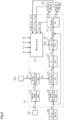
- Fig. 1 shows a vehicle 90 that includes the vehicle motion controller 10 having a driving device 30, a braking device 40, and a driver assistance device 60.
- the vehicle motion controller 10 can manage the motion of the vehicle 90. Specifically, the vehicle motion controller 10 controls the motion of the vehicle 90 by adjusting a longitudinal force that indicates a force acting in a longitudinal direction of the vehicle 90. More specifically, the vehicle motion controller 10 controls the driving device 30 and the braking device 40 so as to adjust the acceleration of the vehicle 90 in the longitudinal direction, thereby adjusting the traveling speed of the vehicle 90.
- Fig. 1 shows one of the axles 92 of the vehicle 90 and one of the wheels 91 that are respectively coupled to the axles 92.
- Each wheel 91 is a driven wheel.
- the vehicle 90 may include an interior monitoring system 70.
- the interior monitoring system 70 includes a monitoring device and a monitoring system controller.
- the monitoring device is, for example, a camera that obtains information in the vehicle 90.
- the monitoring system controller is a processing circuit such as CPU. The monitoring system controller can process the information obtained by the monitoring device so as to send the information to the vehicle motion controller 10.
- the driver assistance device 60 is connected to the vehicle motion controller 10.
- the driver assistance device 60 calculates a request value Rc used to assist the traveling of the vehicle 90.
- the driver assistance device 60 sends the request value Rc to the vehicle motion controller 10.
- the request value Rc is a request value of the longitudinal force, which indicates a force acting in the longitudinal direction of the vehicle 90. When the request value Rc is positive, it indicates that the driver assistance device 60 requests acceleration of vehicle 90. When the request value Rc is negative, it indicates that the driver assistance device 60 requests deceleration of vehicle 90.
- the driver assistance device 60 includes an obtaining device that obtains information of the surroundings of the vehicle 90.
- the obtaining device is, for example, a camera or a radar.
- the obtaining device can obtain the relative distances between the vehicle 90 and, for example, another vehicle and an obstacle that are located around the vehicle 90.
- the obtaining device can also obtain the shape of a road where the vehicle 90 travels and recognizing lanes.
- the driver assistance device 60 includes an assistance calculating unit that calculates the request value Rc.
- the assistance calculating unit is a processing circuit that calculates the request value Rc using the information obtained by the obtaining device.
- the driving device 30 of the vehicle 90 is, for example, a device that generates a driving force using an electric motor.
- Fig. 1 shows a motor generator 31 as an actuator of the driving device 30.
- the motor generator 31 is connected to a battery included in the vehicle 90.
- the driving force is transmitted to the vehicle 90 by causing the motor generator 31 to function as an electric motor.
- the driving force is transmitted to the wheel 91 via the axle 92.
- the motor generator 31 is an example of an actuator that generates a longitudinal force. When the motor generator 31 functions as an electric generator, the vehicle 90 can receive a regenerative braking force.
- the driving device 30 includes a drive controller 32, which is a processing circuit.
- the drive controller 32 functions to control the actuator of the driving device 30.
- the drive controller 32 can generate the driving force by activating the motor generator 31 based on a driving request value Fdq that is sent from the vehicle motion controller 10.
- the actuator of the driving device 30 is not limited to an electric motor and may include an internal combustion engine and a transmission.
- the driving device 30 may include an electric motor, an internal combustion engine, and a transmission.
- the actuator of the driving device 30 may be an in-wheel motor in which an electric motor is coupled to the metal component of each wheel of a vehicle.
- the braking device 40 of the vehicle 90 is, for example, a friction braking device.
- Fig. 1 shows a liquid pressure braking device as an example of the friction braking device.
- the braking device 40 includes a braking mechanism 50 that corresponds to each wheel 91 of the vehicle 90.
- the braking mechanism 50 includes a wheel cylinder 53, a rotor 51 that rotates integrally with the wheel 91, and frictional members 52 that can be pressed against the rotor 51.
- the braking mechanism 50 is, for example, a disc brake.
- the braking mechanism 50 may be a drum brake.
- the braking device 40 which is a liquid pressure braking device, includes a liquid pressure generator.
- the braking device 40 includes a brake actuator 41 to which brake fluid is supplied from the liquid pressure generator.
- the brake actuator 41 is connected to each wheel cylinder 53.
- the liquid pressure braking device can generate a frictional braking force in correspondence with a wheel cylinder (WC) pressure, which is liquid pressure in the wheel cylinder 53 of the braking mechanism 50.
- WC wheel cylinder
- the WC pressure is an example of a value that indicates a pressing force that presses the frictional members 52 against the rotor 51.
- the brake actuator 41 is an example of the actuator that generates the longitudinal force.
- the braking device 40 includes a brake controller 42, which is a processing circuit.
- the brake controller 42 functions to control the brake actuator 41 of the braking device 40.
- the brake controller 42 can generate the braking force by activating the brake actuator 41 based on a braking request value Fbq that is sent from the vehicle motion controller 10.
- the brake controller 42 may obtain the temperatures of the frictional members 52.
- the brake controller 42 may execute an estimating process that estimates the temperatures of the frictional members 52.
- the estimating process can estimate, for example, a frictional member temperature Tp based on the time during which the frictional members 52 are pressed against the rotor 51, the magnitude of the pressing force, and the time during which the frictional members 52 are separated from the rotor 51.
- the frictional member temperature Tp may be obtained based on a detection signal of a temperature sensor that detects the temperatures of the frictional members 52.
- the drive controller 32 and the brake controller 42 may function to execute vehicle stability control that stabilizes the traveling of the vehicle 90.
- vehicle stability control examples include traction control, anti-lock brake control, and anti-skid control.
- the traction control prevents acceleration slip of the driven wheels of the wheels 91 so as to prevent wheelspin of the driven wheels.
- the acceleration slip of the driven wheels is prevented by decreasing the driving force or increasing the braking force.
- the drive controller 32 and the brake controller 42 correspond to an actuator controller that executes the traction control.
- the anti-lock brake control reduces slip amounts of the wheels 91 during braking of the vehicle 90 so as to prevent the wheels 91 from being locked.
- the slip amounts of the wheels 91 are reduced by adjusting the braking force.
- the brake controller 42 corresponds to an actuator controller that executes the anti-lock brake control.
- the anti-skid control reduces the slip amounts of the wheels 91 during turning of the vehicle 90 so as to prevent the vehicle 90 from skidding.
- the slip amounts of the wheels 91 are reduced by adjusting the driving force and the braking force.
- the drive controller 32 and the brake controller 42 correspond to an actuator controller that executes the anti-skid control.
- the actuator controller When starting the traction control, the actuator controller sets a traction control system (TCS) execution flag LT to ON. When ending the traction control, the actuator controller sets the TCS execution flag LT to OFF.
- TCS traction control system
- ABS anti-lock brake system
- the actuator controller When starting the anti-skid control, the actuator controller sets an electronic stability control (ESC) execution flag LE to ON. When ending the anti-skid control, the actuator controller sets the ESC execution flag LE to OFF.
- ESC electronic stability control
- the vehicle stability control is the more prioritized one of the controls that activate the driving device 30 or the braking device 40. While the vehicle stability control is executed, the less prioritized control may be limited.
- the longitudinal force acts in a direction in which the vehicle 90 is accelerated.
- the longitudinal force acts in a direction in which the vehicle 90 is decelerated.
- the longitudinal force as the value becomes farther from 0, it indicates that the force acting on the vehicle 90 increases.
- the motor generator 31 when the driving request value Fdq is positive, the motor generator 31 is controlled such that the driving force increases as the driving request value Fdq increases. When the driving request value Fdq is 0, the driving device 30 transmits no driving force.
- the brake actuator 41 is controlled such that the braking force increases as the braking request value Fbq decreases.
- the braking device 40 applies no braking force.
- the maximum value of the braking request value Fbq is 0.
- the driving request value Fdq may be calculated as a negative value.
- the driving request value Fdq is negative, it indicates that a regenerative braking force is requested, for example.
- the motor generator 31 is controlled such that the regenerative braking force increases as the driving request value Fdq decreases.
- the driving request value Fdq is negative, it indicates that engine braking is requested.
- the controllable range of the longitudinal force of the vehicle 90 is referred to as availability.
- the availability varies depending on, for example, the state quantity of the vehicle 90 while the vehicle 90 is traveling.
- the availability is defined by, for example, a transmittable range AyPT in the driving device 30.
- the transmittable range AyPT is a range of the longitudinal force capable of being generated by the motor generator 31 of the driving device 30.
- the transmittable range AyPT is calculated by, for example, the drive controller 32.
- the transmittable range AyPT varies depending on, for example, the amount of electric power capable of being supplied from the battery to the motor generator 31.
- the maximum value of the transmittable range AyPT is a first maximum longitudinal force Fdx.
- the minimum value of the transmittable range AyPT is a first minimum longitudinal force Fdz.
- the availability is defined by, for example, a brakable range AyBR in the braking device 40.
- the brakable range AyBR is a range of the longitudinal force capable of being generated by the brake actuator 41 of the braking device 40.
- the brakable range AyBR is calculated by, for example, the brake controller 42.
- the brakable range AyBR varies depending on, for example, the temperature of brake fluid.
- the maximum value of the brakable range AyBR is a second maximum longitudinal force Fbx.
- the minimum value of the brakable range AyBR is a second minimum longitudinal force Fbz.
- the availability is also defined by, for example, an execution state of the vehicle stability control.
- the availability as to control that is less prioritized than the vehicle stability control is limited in correspondence with the execution state of the vehicle stability control.
- the prevention of acceleration slip which is the purpose of the traction control, may not be able to be achieved if the longitudinal force is increased during execution of the traction control.
- an increase in the longitudinal force is preferably limited.
- the availability is preferably limited to be narrower when the traction control is executed than when the traction control is not executed. More preferably, the maximum value of the availability is set to 0.
- the reduction of the slip amount which is the purpose of the anti-lock brake control, may not be able to be achieved if the longitudinal force is increased or decreased during execution of the anti-lock brake control.
- an increase and a decrease in the longitudinal force is preferably limited.
- the availability is preferably limited to be narrower when the anti-lock brake control is executed than when the anti-lock brake control is not executed. More preferably, the maximum value and the minimum value of the availability are set to 0.
- the reduction of the slip amount which is the purpose of the anti-skid control, may not be able to be achieved if the longitudinal force is increased or decreased during execution of the anti-skid control.
- an increase and a decrease in the longitudinal force is preferably limited.
- the availability is preferably limited to be narrower when the anti-skid control is executed than when the anti-skid control is not executed. More preferably, the maximum value and the minimum value of the availability are set to 0.
- the availability is also defined by, for example, the frictional member temperature Tp.
- the frictional member temperature Tp changes depending on the frictional member temperature Tp may occur in the relationship between the pressing force that presses the frictional members 52 against the rotor 51 and the braking force that actually acts on the wheels 91 in correspondence with that pressing force.
- the frictional member temperature Tp becomes excessively high, the braking force does not easily increase even if the pressing force is increased. That is, the longitudinal force may not be able to be reduced by activating the braking device 40.
- the value of the second minimum longitudinal force Fbz which is the minimum value of the brakable range AyBR, becomes closer to 0 when the frictional member temperature Tp is high than when the frictional member temperature Tp is low.
- the transmittable range AyPT, the brakable range AyBR, the execution state of the vehicle stability control, and the frictional member temperature Tp are examples of the information that indicates the availability, which is the controllable range of the longitudinal force of the vehicle 90.
- the availability may be limited to be narrower than the transmittable range AyPT or the brakable range AyBR.
- the vehicle 90 includes various types of sensors.
- Figs. 1 and 2 show a wheel speed sensor SE1 and a longitudinal acceleration sensor SE2 as examples of the various sensors. Detection signals from the various sensors are input to the vehicle motion controller 10.
- the wheel speed sensor SE1 detects a wheel speed Vw.
- the wheel speed sensor SE1 is disposed at each wheel 91. Based on the detection signal from the wheel speed sensor SE1, the vehicle motion controller 10 can calculate the wheel speed Vw of each wheel 91. Based on each wheel speed Vw, the vehicle motion controller 10 can calculate a vehicle speed Vx.
- the vehicle speed Vx indicates the traveling speed of the vehicle 90.
- the longitudinal acceleration sensor SE2 detects the acceleration in the longitudinal direction of the vehicle 90.
- the vehicle motion controller 10 can obtain the detection signal from the longitudinal acceleration sensor SE2 as an acceleration detected value Gx.
- the vehicle motion controller 10 executes driver assistance control that automatically adjusts the traveling speed of the vehicle 90 based on the request value Rc from the driver assistance device 60.
- Examples of the driver assistance control include control of autonomous driving, autonomous parking, adaptive cruise control, lane keep assist, and collision avoidance braking.
- the driver assistance control is less prioritized than the vehicle stability control.
- the vehicle motion controller 10 is connected to the drive controller 32 and the brake controller 42. Information can be exchanged between the vehicle motion controller 10, the drive controller 32, and the brake controller 42.
- the drive controller 32 and the brake controller 42 can exchange information via the vehicle motion controller 10.
- the drive controller 32 and the brake controller 42 may be directly connected to each other. In this case, information can be exchanged between the drive controller 32 and the brake controller 42.
- the vehicle motion controller 10 is a processing circuit including functional units that execute various types of control.
- Fig. 2 shows a vehicle speed calculating unit 11, an actual acceleration calculating unit 12, a target acceleration calculating unit 14, a difference calculating unit 15, a proportional-integral (PI) controlling unit 16, a limit processing unit 17, an obtaining unit 20, and a request outputting unit 19 as examples of the functional units.
- the functional units of the vehicle motion controller 10 can exchange information with each other.
- the vehicle speed calculating unit 11 calculates the traveling speed of the vehicle 90, namely, the vehicle speed Vx, from the wheel speed Vw, which is based on the detection signal of the wheel speed sensor SE1.
- the actual acceleration calculating unit 12 calculates an actual acceleration Ga from a value obtained by differentiating the vehicle speed Vx with respect to time and from the acceleration detected value Gx, which is based on the detection signal of the longitudinal acceleration sensor SE2.
- the target acceleration calculating unit 14 calculates a target acceleration Gt. More specifically, the target acceleration calculating unit 14 calculates the target acceleration Gt by converting the request value Rc, which has a dimension of the longitudinal force, into an acceleration. When the vehicle 90 is requested to accelerate, the target acceleration Gt has a positive value. When the vehicle 90 is requested to decelerate, the target acceleration Gt has a negative value.
- the difference calculating unit 15 calculates a difference hG in the acceleration by subtracting the actual acceleration Ga, which has been calculated by the actual acceleration calculating unit 12, from the target acceleration Gt, which has been calculated by the target acceleration calculating unit 14.
- the PI controlling unit 16 and the limit processing unit 17 correspond to a feedback controlling unit. Based on the difference hG, the feedback controlling unit calculates a feedback control amount used to reduce the difference hG. The feedback controlling unit outputs a limit control amount Rs as the feedback control amount.
- the request outputting unit 19 calculates a request longitudinal force used to control the driving device 30 and the braking device 40.
- the request outputting unit 19 outputs the driving request value Fdq and the braking request value Fbq as the request longitudinal force.
- the sum of the request value Rc and the limit control amount Rs is input to the request outputting unit 19 as a corrected request value Rt. That is, the greater the limit control amount Rs, the greater the corrected request value Rt. The smaller the limit control amount Rs, the smaller the corrected request value Rt.
- the request outputting unit 19 calculates the driving request value Fdq and the braking request value Fbq in correspondence with the corrected request value Rt.
- the request outputting unit 19 outputs the driving request value Fdq to the driving device 30.
- the request outputting unit 19 outputs the braking request value Fbq to the braking device 40.
- the obtaining unit 20 obtains the availability. More specifically, the obtaining unit 20 can obtain the following information as the information indicating the availability.
- the obtaining unit 20 obtains the first maximum longitudinal force Fdx and the first minimum longitudinal force Fdz of the transmittable range AyPT from the drive controller 32 of the driving device 30.
- the obtaining unit 20 obtains the second maximum longitudinal force Fbx and the second minimum longitudinal force Fbz of the brakable range AyBR from the brake controller 42 of the braking device 40.
- the obtaining unit 20 obtains the TCS execution flag LT, the ABS execution flag LA, and the ESC execution flag LE from the actuator controller.
- the obtaining unit 20 obtains the frictional member temperature Tp from the brake controller 42.
- the obtaining unit 20 obtains the driving request value Fdq and the braking request value Fbq from the request outputting unit 19.
- the obtaining unit 20 activates an increase prohibiting flag Ka and a decrease prohibiting flag Kb in correspondence with the obtained availability and the request longitudinal force.
- the flag activation by the obtaining unit 20 will be described in detail later.
- the feedback controlling unit will now be described in more detail.
- the PI controlling unit 16 outputs a feedback (FB) control amount Rh based on the difference hG.
- the calculation executed by the PI controlling unit 16 includes proportional control and integral control.
- the PI controlling unit 16 calculates the FB control amount Rh as the feedback control amount, which is used to reduce the difference hG. While calculating the FB control amount Rh, the PI controlling unit 16 converts the value of the FB control amount Rh into the dimension of the longitudinal force.
- the PI controlling unit 16 suspends the integral control. Even during a period in which the integral control is suspended, the PI controlling unit 16 continues calculation of the FB control amount Rh. That is, an integral term is not added to the FB control amount Rh calculated in this period.
- the FB control amount Rh is input to the limit processing unit 17.
- the limit processing unit 17 outputs the limit control amount Rs in correspondence with the increase prohibiting flag Ka and the decrease prohibiting flag Kb.
- the limit processing unit 17 When the increase prohibiting flag Ka and the decrease prohibiting flag Kb are OFF, the limit processing unit 17 outputs the input FB control amount Rh as the limit control amount Rs.
- the limit processing unit 17 prohibits the feedback control amount from increasing. This process will now be described in detail.
- the limit processing unit 17 compares the input FB control amount Rh with the limit control amount Rs that was previously output. When the input FB control amount Rh is greater than or equal to the limit control amount Rs that was previously output, the limit processing unit 17 outputs a limit control amount Rs having the same value as the limit control amount Rs that was previously output. When the input FB control amount Rh is less than the limit control amount Rs that was previously output, the limit processing unit 17 outputs the input FB control amount Rh as the limit control amount Rs.
- the limit processing unit 17 prohibits the feedback control amount from decreasing. This process will now be described in detail.
- the limit processing unit 17 compares the input FB control amount Rh with the limit control amount Rs that was previously output. When the input FB control amount Rh is less than or equal to the limit control amount Rs that was previously output, the limit processing unit 17 outputs a limit control amount Rs having the same value as the limit control amount Rs that was previously output. When the input FB control amount Rh is greater than the limit control amount Rs that was previously output, the limit processing unit 17 outputs the input FB control amount Rh as the limit control amount Rs.
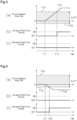
- Fig. 3 is an example of a case where the driving request value Fdq increases during execution of the driver assistance control.
- Section (a) of Fig. 3 shows the transmittable range AyPT and the driving request value Fdq that are input to the obtaining unit 20.
- the driving request value Fdq is 0 in a period prior to the point in time t11. After the point in time t11, the driving request value Fdq increases. After the point in time t12, the driving request value Fdq increasing after the point in time t11 is greater than the first maximum longitudinal force Fdx.
- the obtaining unit 20 determines that the driving request value Fdq is greater than the maximum value of the availability. Then, the obtaining unit 20 sets the increase prohibiting flag Ka to ON. That is, the obtaining unit 20 determines that the driving request value Fdq is greater than the maximum value of the availability at the point in time t12. Then, as shown in section (b) of Fig. 3 , the obtaining unit 20 sets the increase prohibiting flag Ka to ON at the point in time t12. As a result, the limit processing unit 17 prohibits the feedback control amount from increasing after the point in time t12.
- the obtaining unit 20 determines that the driving request value Fdq is in the range of the availability. Then, the obtaining unit 20 sets the increase prohibiting flag Ka to OFF.
- the decrease prohibiting flag Kb shown in section (c) of Fig. 3 is not activated by the obtaining unit 20. That is, the decrease prohibiting flag Kb remains OFF after the point in time t12. As a result, the limit processing unit 17 does not prohibit the feedback control amount from decreasing. Thus, the feedback control amount is permitted to decrease even after the point in time t12.
- Fig. 4 is an example of a case where the driving request value Fdq decreases during execution of the driver assistance control.
- Section (a) of Fig. 4 shows the transmittable range AyPT and the driving request value Fdq that are input to the obtaining unit 20.
- the driving request value Fdq is 0 in a period prior to the point in time t21. After the point in time t21, the driving request value Fdq decreases. After the point in time t22, the driving request value Fdq decreasing after the point in time t21 is less than the first minimum longitudinal force Fdz.
- the obtaining unit 20 determines that the driving request value Fdq is less than the minimum value of the availability. Then, the obtaining unit 20 sets the decrease prohibiting flag Kb to ON. That is, the obtaining unit 20 determines that the driving request value Fdq is less than the minimum value of the availability at the point in time t22. As shown in section (c) of Fig. 4 , the obtaining unit 20 sets the decrease prohibiting flag Kb to ON at the point in time t22. As a result, the limit processing unit 17 prohibits the feedback control amount from decreasing after the point in time t22.
- the obtaining unit 20 determines that the driving request value Fdq is in the range of the availability. Then, the obtaining unit 20 sets the decrease prohibiting flag Kb to OFF.
- the increase prohibiting flag Ka shown in section (b) of Fig. 4 is not activated by the obtaining unit 20. That is, the increase prohibiting flag Ka remains OFF after the point in time t22. As a result, the limit processing unit 17 does not prohibit the feedback control amount from increasing. Thus, the feedback control amount is permitted to increase even after the point in time t22.
- Fig. 5 is an example of a case where the braking request value Fbq decreases during execution of the driver assistance control.
- Section (a) of Fig. 5 shows the brakable range AyBR and the braking request value Fbq that are input to the obtaining unit 20.
- the braking request value Fbq is 0 in a period prior to the point in time t31. After the point in time t31, the braking request value Fbq decreases. After the point in time t32, the braking request value Fbq decreasing after the point in time t31 is less than the second minimum longitudinal force Fbz.
- the obtaining unit 20 determines that the braking request value Fbq is less than the minimum value of the availability. Then, the obtaining unit 20 sets the decrease prohibiting flag Kb to ON. That is, the obtaining unit 20 determines that the braking request value Fbq is less than the minimum value of the availability at the point in time t32. As shown in section (c) of Fig. 5 , the obtaining unit 20 sets the decrease prohibiting flag Kb to ON at the point in time t32. As a result, the limit processing unit 17 prohibits the feedback control amount from decreasing after the point in time t32.
- the obtaining unit 20 determines that the braking request value Fbq is in the range of the availability. Then, the obtaining unit 20 sets the decrease prohibiting flag Kb to OFF.
- the increase prohibiting flag Ka shown in section (b) of Fig. 5 is not activated by the obtaining unit 20. That is, the increase prohibiting flag Ka remains OFF after the point in time t32. As a result, the limit processing unit 17 does not prohibit the feedback control amount from increasing. Thus, the feedback control amount is permitted to increase even after the point in time t32.
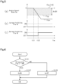
- Fig. 6 illustrates the flow of a process executed by the obtaining unit 20. This processing routine is repeatedly executed in predetermined cycles when the driver assistance control is executed.
- the obtaining unit 20 When the processing routine is started, the obtaining unit 20 first determines in step S101 whether the TCS execution flag LT is set to ON. When the TCS execution flag LT is set to ON (S101: YES), the obtaining unit 20 advances the process to step S102. In step S102, the obtaining unit 20 sets the increase prohibiting flag Ka to ON. Subsequently, the obtaining unit 20 ends the processing routine. As a result, the limit processing unit 17 prohibits the feedback control amount from increasing. At this time, the obtaining unit 20 does not activate the decrease prohibiting flag Kb. Thus, the decrease prohibiting flag Kb is OFF, which has an initial value. That is, the limit processing unit 17 permits the feedback control amount to decrease.
- step S101 when the TCS execution flag LT is not set to ON, that is, when the TCS execution flag LT is set to OFF (S101: NO), the obtaining unit 20 advances the process to step S103.
- step S103 the obtaining unit 20 sets the increase prohibiting flag Ka to OFF. Subsequently, the obtaining unit 20 ends the processing routine.
- the limit processing unit 17 permits the feedback control amount to increase.
- Fig. 7 illustrates the flow of a process executed by the obtaining unit 20. This processing routine is repeatedly executed in predetermined cycles when the driver assistance control is executed.
- the obtaining unit 20 When the processing routine is started, the obtaining unit 20 first determines in step S201 whether the ABS execution flag LA is set to ON. When the ABS execution flag LA is set to ON (S201: YES), the obtaining unit 20 advances the process to step S202. In step S202, the obtaining unit 20 sets the increase prohibiting flag Ka and the decrease prohibiting flag Kb to ON. Subsequently, the obtaining unit 20 ends the processing routine. As a result, the limit processing unit 17 prohibits the feedback control amount from increasing and decreasing. That is, the limit processing unit 17 keeps the feedback control amount constant.
- step S201 when the ABS execution flag LA is not set to ON, that is, when the ABS execution flag LA is set to OFF (S201: NO), the obtaining unit 20 advances the process to step S203.
- step S203 the obtaining unit 20 determines whether the ESC execution flag LE is set to ON.
- the obtaining unit 20 advances the process to step S202. That is, the obtaining unit 20 sets the increase prohibiting flag Ka and the decrease prohibiting flag Kb to ON.
- the limit processing unit 17 prohibits the feedback control amount from increasing and decreasing. That is, the limit processing unit 17 keeps the feedback control amount constant.
- step S203 when the ESC execution flag LE is not set to ON, that is, when the ESC execution flag LE is set to OFF (S203: NO), the obtaining unit 20 advances the process to step S204.
- step S204 the obtaining unit 20 sets the increase prohibiting flag Ka and the decrease prohibiting flag Kb to OFF. Subsequently, the obtaining unit 20 ends the processing routine.
- the limit processing unit 17 permits the feedback control amount to increase and decrease.
- Fig. 8 illustrates the flow of a process executed by the obtaining unit 20. This processing routine is repeatedly executed in predetermined cycles when the driver assistance control is executed.
- the obtaining unit 20 first determines in step S301 whether the frictional member temperature Tp is greater than or equal to the determination temperature Tx.
- the determination temperature Tx has a value stored in the obtaining unit 20 in order to determine whether the frictional member temperature Tp is excessively increasing.
- the determination temperature Tx is preset based on, for example, experiments.
- step S301 when the frictional member temperature Tp is greater than or equal to the determination temperature Tx (S301: YES), the obtaining unit 20 advances the process to step S302.
- step S302 the obtaining unit 20 sets the decrease prohibiting flag Kb to ON. Subsequently, the obtaining unit 20 ends the processing routine.
- the limit processing unit 17 prohibits the feedback control amount from decreasing. At this time, the obtaining unit 20 does not activate the increase prohibiting flag Ka.
- the increase prohibiting flag Ka is OFF, which has an initial value. That is, the limit processing unit 17 permits the feedback control amount to increase.
- step S301 when the frictional member temperature Tp is lower than the determination temperature Tx (S301: NO), the obtaining unit 20 advances the process to step S303.
- step S303 the obtaining unit 20 sets the decrease prohibiting flag Kb to OFF. Subsequently, the obtaining unit 20 ends the processing routine. As a result, the limit processing unit 17 permits the feedback control amount to decrease.
- the feedback control amount when the driving request value Fdq is greater than the first maximum longitudinal force Fdx, the longitudinal force corresponding to the driving request value Fdq cannot be gained. If the feedback control amount is permitted to increase in this state, the feedback control amount may be further increased in a state where the longitudinal force is not increased. In such a case, the feedback control amount unnecessarily increases without an increase in the longitudinal force that actually acts on the vehicle 90. An excessive increase in the feedback control amount may hinder the actual acceleration Ga from converging to the target acceleration Gt. In addition, an excessive increase in the feedback control amount may cause the actual acceleration Ga to vary suddenly when the longitudinal force corresponding to the driving request value Fdq becomes able to be gained.
- the vehicle motion controller 10 prohibits the feedback control amount from increasing when the driving request value Fdq is greater than the first maximum longitudinal force Fdx. This prevents the feedback control amount from excessively increasing. Thus, the feedback control is executed with the availability taken into account.
- the feedback control amount when the driving request value Fdq is less than the first minimum longitudinal force Fdz, the longitudinal force corresponding to the driving request value Fdq cannot be gained. If the feedback control amount is permitted to decrease in this state, the feedback control amount may be further decreased in a state where the longitudinal force is not decreased. In such a case, the feedback control amount unnecessarily decreases without a decrease in the longitudinal force that actually acts on the vehicle 90. An excessive decrease in the feedback control amount may hinder the actual acceleration Ga from converging to the target acceleration Gt. In addition, an excessive decrease in the feedback control amount may cause the actual acceleration Ga to vary suddenly when the longitudinal force corresponding to the driving request value Fdq becomes able to be gained.
- the vehicle motion controller 10 prohibits the feedback control amount from decreasing when the driving request value Fdq is less than the first minimum longitudinal force Fdz. This prevents the feedback control amount from excessively decreasing.
- the feedback control is executed with the availability taken into account.
- the feedback control amount when the braking request value Fbq is less than the second minimum longitudinal force Fbz, the longitudinal force corresponding to the braking request value Fbq cannot be gained. If the feedback control amount is permitted to decrease in this state, the feedback control amount may be further decreased in a state where the longitudinal force is not decreased. In such a case, the feedback control amount unnecessarily decreases without a decrease in the longitudinal force that actually acts on the vehicle 90. An excessive decrease in the feedback control amount may hinder the actual acceleration Ga from converging to the target acceleration Gt. In addition, an excessive decrease in the feedback control amount may cause the actual acceleration Ga to vary suddenly when the longitudinal force corresponding to the braking request value Fbq becomes able to be gained.
- the vehicle motion controller 10 prohibits the feedback control amount from decreasing when the braking request value Fbq is less than the second minimum longitudinal force Fbz. This prevents the feedback control amount from excessively decreasing.
- the feedback control is executed with the availability taken into account.
- the feedback control amount may be further increased in a state where the longitudinal force is not increased. In such a case, the feedback control amount unnecessarily increases without an increase in the longitudinal force that actually acts on the vehicle 90. An excessive increase in the feedback control amount may hinder the actual acceleration Ga from converging to the target acceleration Gt.
- the vehicle motion controller 10 determines that the request longitudinal force is outside the range of the availability and determines that the control according to the request longitudinal force cannot be executed.
- the vehicle motion controller 10 prohibits the feedback control amount from increasing. This prevents the feedback control amount from excessively increasing.
- the feedback control is executed with the availability taken into account. Additionally, the time for the actual acceleration Ga to converge to the target acceleration Gt is prevented from increasing in the feedback control executed subsequent to the end of the traction control.
- the feedback control amount may be further increased or decreased in a state where the longitudinal force is not increased or decreased. In such a case, the feedback control amount unnecessarily increases or decreases without an increase or decrease in the longitudinal force that actually acts on the vehicle 90. An excessive increase or excessive decrease in the feedback control amount may hinder the actual acceleration Ga from converging to the target acceleration Gt.
- the vehicle motion controller 10 determines that the request longitudinal force is outside the range of the availability and determines that the control according to the request longitudinal force cannot be executed.
- the feedback control amount is kept constant. This prevents the feedback control amount from excessively increasing or excessively decreasing.
- the feedback control is executed with the availability taken into account. Additionally, the time for the actual acceleration Ga to converge to the target acceleration Gt is prevented from increasing in the feedback control executed subsequent to the end of the anti-lock brake control or the anti-skid control.
- the friction braking device in a case where the frictional member temperature Tp becomes excessively high, the braking force does not easily increase even if the pressing force is increased. That is, the longitudinal force may not be able to be reduced by activating the friction braking device. If the feedback control amount is permitted to decrease in this state, the feedback control amount may be further decreased in a state where the longitudinal force is not decreased. In such a case, the feedback control amount unnecessarily decreases without a decrease in the longitudinal force that actually acts on the vehicle 90. An excessive decrease in the feedback control amount may hinder the actual acceleration Ga from converging to the target acceleration Gt.
- the vehicle motion controller 10 determines that the request longitudinal force is outside the range of the availability and determines that the control according to the request longitudinal force cannot be executed.
- the vehicle motion controller 10 prohibits the feedback control amount from decreasing. This prevents the feedback control amount from excessively decreasing.
- the feedback control is executed with the availability taken into account. Further, prohibiting the feedback control amount from decreasing prevents situations in which the braking request value Fbq is decreased; that is, prevents situations in which the braking force is increased. This prevents the frictional member temperature Tp from further increasing.
- the vehicle motion controller 10 continues the feedback control. More specifically, even when the request longitudinal force is outside the range of the availability, the feedback controlling unit continues to calculate the FB control amount Rh. Thus, after the request longitudinal force returns to the inside of the range of the availability, the feedback control that reduces the difference hG between the target acceleration Gt and the actual acceleration Ga is executed continuously.
- the vehicle motion controller 10 suspends the integral control.
- the FB control amount Rh is unaffected by the elapse of time in a period in which the request longitudinal force is outside the range of the availability. This allows the feedback control to be executed continuously.
- a replacement request value Rr based on information from the interior monitoring system 70, may be input to the vehicle motion controller 10.
- the replacement request value Rr is a request value of the longitudinal force.
- the replacement request value Rr is output from the interior monitoring system 70 when the driver is unable to operate the vehicle 90.
- the target acceleration Gt may be calculated based on the replacement request value Rr instead of the request value from the driver assistance device 60.
- the feedback control amount when anti-lock brake control is executed, the feedback control amount is kept constant. Instead, when anti-lock brake control is executed, the feedback control amount may be permitted to increase while the feedback control amount is prevented from decreasing.
- the feedback control amount when the traction control is executed, the feedback control amount is prohibited from increasing. Instead, when the traction control is executed, the feedback control amount may be prohibited from increasing and decreasing. That is, when the traction control is executed, the feedback control amount may be kept constant.
- the feedback control amount when the frictional member temperature Tp is greater than or equal to the determination temperature Tx, the feedback control amount is prevented from decreasing. Instead, when the frictional member temperature Tp increases at a speed that is greater than or equal to a given determination speed, the feedback control amount may be prevented from decreasing.
- the request value Rc has a dimension of the longitudinal force.
- the request value from the driver assistance device 60 simply needs to correlate with the longitudinal force.
- the request value may have a dimension of, for example, an acceleration.
- the vehicle motion controller 10 does not need to calculate the target acceleration Gt and thus does not have to include the target acceleration calculating unit 14.
- the request value may have a dimension of axle torque.
- the feedback controlling unit of the above-described embodiment is an example.
- the process that prohibits the feedback control amount from increasing or decreasing executed by the feedback controlling unit is not limited to the process explained in the above-described embodiment.
- the functions provided by the drive controller 32, the brake controller 42, and the assistance calculating unit may be partially or entirely provided by the vehicle motion controller 10.
- the functions provided by the vehicle motion controller 10 may be provided by another processing circuit that is connected to the vehicle motion controller 10.
- the vehicle 90 does not have to include the friction braking device.
- a device that generates a regenerative braking force corresponds to the braking device.
- a vehicle motion controller includes a feedback controlling unit that executes feedback control in which a difference between a target acceleration corresponding to a request value from a driver assistance device and an actual acceleration of a vehicle is an input, thereby calculating a control amount used to reduce the difference, a request outputting unit that calculates a request longitudinal force based on the control amount, the request longitudinal force controlling an actuator, and an obtaining unit that obtains, as availability, a range of a longitudinal force capable of being generated by the actuator, the availability being a controllable range of the longitudinal force.
- the feedback controlling unit prohibits the control amount from decreasing when the request longitudinal force is less than a minimum value in the availability.
Applications Claiming Priority (1)
| Application Number | Priority Date | Filing Date | Title |
|---|---|---|---|
| JP2021151872A JP7394095B2 (ja) | 2021-09-17 | 2021-09-17 | 車両運動制御装置 |
Publications (1)
| Publication Number | Publication Date |
|---|---|
| EP4151484A1 true EP4151484A1 (en) | 2023-03-22 |
Family
ID=82838934
Family Applications (1)
| Application Number | Title | Priority Date | Filing Date |
|---|---|---|---|
| EP22188699.7A Pending EP4151484A1 (en) | 2021-09-17 | 2022-08-04 | Vehicle motion controller |
Country Status (4)
| Country | Link |
|---|---|
| US (1) | US20230089908A1 (ja) |
| EP (1) | EP4151484A1 (ja) |
| JP (1) | JP7394095B2 (ja) |
| CN (1) | CN115817525A (ja) |
Citations (5)
| Publication number | Priority date | Publication date | Assignee | Title |
|---|---|---|---|---|
| US20160176403A1 (en) * | 2014-12-23 | 2016-06-23 | Ford Global Technologies, Llc | Adaptive Cruise Control While Towing |
| JP2019098972A (ja) | 2017-12-04 | 2019-06-24 | トヨタ自動車株式会社 | 運転支援装置 |
| US20200171956A1 (en) * | 2018-12-03 | 2020-06-04 | Hyundai Motor Company | Eco-friendly vehicle and hill descent control method for the same |
| EP3851346A1 (en) * | 2020-01-15 | 2021-07-21 | Volvo Truck Corporation | An inverse tyre model for advanced vehicle motion management |
| WO2021144065A1 (en) * | 2020-01-15 | 2021-07-22 | Volvo Truck Corporation | Vehicle motion management based on torque request with speed limit |
Family Cites Families (3)
| Publication number | Priority date | Publication date | Assignee | Title |
|---|---|---|---|---|
| JP2020019456A (ja) | 2018-08-03 | 2020-02-06 | 本田技研工業株式会社 | 車両制御装置、車両制御方法、およびプログラム |
| JP7056474B2 (ja) | 2018-08-30 | 2022-04-19 | トヨタ自動車株式会社 | 制御装置、マネージャ、システム、制御方法及び車両 |
| JP7067386B2 (ja) | 2018-09-21 | 2022-05-16 | トヨタ自動車株式会社 | 制駆動力制御装置 |
-
2021
- 2021-09-17 JP JP2021151872A patent/JP7394095B2/ja active Active
-
2022
- 2022-08-04 EP EP22188699.7A patent/EP4151484A1/en active Pending
- 2022-09-06 US US17/903,321 patent/US20230089908A1/en active Pending
- 2022-09-09 CN CN202211102745.XA patent/CN115817525A/zh active Pending
Patent Citations (5)
| Publication number | Priority date | Publication date | Assignee | Title |
|---|---|---|---|---|
| US20160176403A1 (en) * | 2014-12-23 | 2016-06-23 | Ford Global Technologies, Llc | Adaptive Cruise Control While Towing |
| JP2019098972A (ja) | 2017-12-04 | 2019-06-24 | トヨタ自動車株式会社 | 運転支援装置 |
| US20200171956A1 (en) * | 2018-12-03 | 2020-06-04 | Hyundai Motor Company | Eco-friendly vehicle and hill descent control method for the same |
| EP3851346A1 (en) * | 2020-01-15 | 2021-07-21 | Volvo Truck Corporation | An inverse tyre model for advanced vehicle motion management |
| WO2021144065A1 (en) * | 2020-01-15 | 2021-07-22 | Volvo Truck Corporation | Vehicle motion management based on torque request with speed limit |
Also Published As
| Publication number | Publication date |
|---|---|
| CN115817525A (zh) | 2023-03-21 |
| JP2023044043A (ja) | 2023-03-30 |
| US20230089908A1 (en) | 2023-03-23 |
| JP7394095B2 (ja) | 2023-12-07 |
Similar Documents
| Publication | Publication Date | Title |
|---|---|---|
| EP2876007B1 (en) | Vehicle brake force generation device | |
| JP6380309B2 (ja) | 車両の制御装置 | |
| JP6361916B2 (ja) | 車両制御装置および車両制御方法 | |
| US20170174194A1 (en) | Method for operating a vehicle | |
| US9283936B2 (en) | Braking force control apparatus for vehicle | |
| US9694794B2 (en) | Vehicle control device | |
| JP4254936B2 (ja) | 車両の警報発生装置 | |
| CN107709123B (zh) | 车辆用控制装置 | |
| CN108944948B (zh) | 一种车辆制动控制系统和方法 | |
| JP2006506270A (ja) | 車両の縦方向の加速を制御するための方法及び装置 | |
| US9764720B2 (en) | Method for operating an electric motor for braking a vehicle, and control device for an electric motor designed at least for braking a vehicle | |
| JP6476801B2 (ja) | 制駆動力制御装置及び制駆動力制御方法 | |
| US20200086885A1 (en) | Vehicle Control Device | |
| US20130124063A1 (en) | Travel control device | |
| EP4151484A1 (en) | Vehicle motion controller | |
| US11691520B2 (en) | System for an electrically driven vehicle, vehicle having same and method for same | |
| EP4151480A1 (en) | Vehicle motion controller | |
| JP2005306281A (ja) | 減速制御装置 | |
| JP5300838B2 (ja) | 自動車の後輪の少なくとも1つの方向転換アクチュエータに適用される方向転換設定点を管理するための方法と装置 | |
| US20230242146A1 (en) | Vehicle controller, computer-readable medium storing vehicle control program, and vehicle control method | |
| JP5797573B2 (ja) | 車両制御装置 | |
| EP4151478A1 (en) | Vehicle controller and vehicle control method | |
| US20230093196A1 (en) | Vehicle controller and vehicle control method | |
| EP3409548A1 (en) | Vehicle driving assistance device | |
| CN115616943A (zh) | 车辆制动方法、设备、车身稳定系统、车辆和存储介质 |
Legal Events
| Date | Code | Title | Description |
|---|---|---|---|
| PUAI | Public reference made under article 153(3) epc to a published international application that has entered the european phase |
Free format text: ORIGINAL CODE: 0009012 |
|
| STAA | Information on the status of an ep patent application or granted ep patent |
Free format text: STATUS: REQUEST FOR EXAMINATION WAS MADE |
|
| 17P | Request for examination filed |
Effective date: 20220804 |
|
| AK | Designated contracting states |
Kind code of ref document: A1 Designated state(s): AL AT BE BG CH CY CZ DE DK EE ES FI FR GB GR HR HU IE IS IT LI LT LU LV MC MK MT NL NO PL PT RO RS SE SI SK SM TR |