EP4151380B1 - Zweiloch-kernbohrmaschine - Google Patents
Zweiloch-kernbohrmaschine Download PDFInfo
- Publication number
- EP4151380B1 EP4151380B1 EP22808926.4A EP22808926A EP4151380B1 EP 4151380 B1 EP4151380 B1 EP 4151380B1 EP 22808926 A EP22808926 A EP 22808926A EP 4151380 B1 EP4151380 B1 EP 4151380B1
- Authority
- EP
- European Patent Office
- Prior art keywords
- plate
- drilling machine
- coupled
- moving plate
- core drilling
- Prior art date
- Legal status (The legal status is an assumption and is not a legal conclusion. Google has not performed a legal analysis and makes no representation as to the accuracy of the status listed.)
- Active
Links
Images


Classifications
-
- B—PERFORMING OPERATIONS; TRANSPORTING
- B28—WORKING CEMENT, CLAY, OR STONE
- B28D—WORKING STONE OR STONE-LIKE MATERIALS
- B28D1/00—Working stone or stone-like materials, e.g. brick, concrete or glass, not provided for elsewhere; Machines, devices, tools therefor
- B28D1/02—Working stone or stone-like materials, e.g. brick, concrete or glass, not provided for elsewhere; Machines, devices, tools therefor by sawing
- B28D1/04—Working stone or stone-like materials, e.g. brick, concrete or glass, not provided for elsewhere; Machines, devices, tools therefor by sawing with circular or cylindrical saw-blades or saw-discs
- B28D1/041—Working stone or stone-like materials, e.g. brick, concrete or glass, not provided for elsewhere; Machines, devices, tools therefor by sawing with circular or cylindrical saw-blades or saw-discs with cylinder saws, e.g. trepanning; saw cylinders, e.g. having their cutting rim equipped with abrasive particles
-
- B—PERFORMING OPERATIONS; TRANSPORTING
- B23—MACHINE TOOLS; METAL-WORKING NOT OTHERWISE PROVIDED FOR
- B23B—TURNING; BORING
- B23B39/00—General-purpose boring or drilling machines or devices; Sets of boring and/or drilling machines
- B23B39/16—Drilling machines with a plurality of working-spindles; Drilling automatons
- B23B39/161—Drilling machines with a plurality of working-spindles; Drilling automatons with parallel work spindles
- B23B39/162—Drilling machines with a plurality of working-spindles; Drilling automatons with parallel work spindles having gear transmissions
-
- B—PERFORMING OPERATIONS; TRANSPORTING
- B23—MACHINE TOOLS; METAL-WORKING NOT OTHERWISE PROVIDED FOR
- B23B—TURNING; BORING
- B23B51/00—Tools for drilling machines
- B23B51/04—Drills for trepanning
-
- B—PERFORMING OPERATIONS; TRANSPORTING
- B23—MACHINE TOOLS; METAL-WORKING NOT OTHERWISE PROVIDED FOR
- B23B—TURNING; BORING
- B23B2250/00—Compensating adverse effects during turning, boring or drilling
- B23B2250/12—Cooling and lubrication
-
- B—PERFORMING OPERATIONS; TRANSPORTING
- B23—MACHINE TOOLS; METAL-WORKING NOT OTHERWISE PROVIDED FOR
- B23B—TURNING; BORING
- B23B2270/00—Details of turning, boring or drilling machines, processes or tools not otherwise provided for
- B23B2270/14—Constructions comprising exactly two similar components
-
- B—PERFORMING OPERATIONS; TRANSPORTING
- B23—MACHINE TOOLS; METAL-WORKING NOT OTHERWISE PROVIDED FOR
- B23B—TURNING; BORING
- B23B39/00—General-purpose boring or drilling machines or devices; Sets of boring and/or drilling machines
- B23B39/16—Drilling machines with a plurality of working-spindles; Drilling automatons
- B23B39/161—Drilling machines with a plurality of working-spindles; Drilling automatons with parallel work spindles
- B23B39/167—Drilling machines with a plurality of working-spindles; Drilling automatons with parallel work spindles having belt and chain transmissions
-
- B—PERFORMING OPERATIONS; TRANSPORTING
- B28—WORKING CEMENT, CLAY, OR STONE
- B28D—WORKING STONE OR STONE-LIKE MATERIALS
- B28D7/00—Accessories specially adapted for use with machines or devices of the preceding groups
- B28D7/02—Accessories specially adapted for use with machines or devices of the preceding groups for removing or laying dust, e.g. by spraying liquids; for cooling work
-
- Y—GENERAL TAGGING OF NEW TECHNOLOGICAL DEVELOPMENTS; GENERAL TAGGING OF CROSS-SECTIONAL TECHNOLOGIES SPANNING OVER SEVERAL SECTIONS OF THE IPC; TECHNICAL SUBJECTS COVERED BY FORMER USPC CROSS-REFERENCE ART COLLECTIONS [XRACs] AND DIGESTS
- Y10—TECHNICAL SUBJECTS COVERED BY FORMER USPC
- Y10T—TECHNICAL SUBJECTS COVERED BY FORMER US CLASSIFICATION
- Y10T408/00—Cutting by use of rotating axially moving tool
- Y10T408/36—Machine including plural tools
- Y10T408/38—Plural, simultaneously operational tools
- Y10T408/3811—Plural, simultaneously operational tools with provision for adjustment of relationship of axes
Definitions
- the present invention relates to a two-hole core drilling machine as per the preambles of appended claims 1 and 8.
- a core drilling machine is a mechanical apparatus for drilling a hole into a wall, a ceiling, etc. upon piping construction in a building.
- a core drilling machine constitutes a core drill assembly together with various devices configured to manipulate a core drill.
- a general core drill assembly which is currently used, includes a base fixed to a structure, into which a hole is to be drilled, by an anchor bolt, a stand disposed to be perpendicular to the base and formed with a rack at one side surface thereof, a driving body with a pinion mounted therein, the driving body being vertically reciprocable along the stand in accordance with a rotating operation of a handle, and a core drill mounted to the driving body and configured to drill a hole into a particular portion of the structure.
- the core drill is constituted by a core bit configured to drill a hole into the structure through frictional contact between the core bit and the structure, and a drive motor configured to rotate the core bit at a high speed.
- the core drill assembly having the above-mentioned configuration operates as follows.
- the handle installed at the driving body is rotated in a state in which the base is fixed to a wall or a bottom surface of the structure using a plurality of anchor bolts
- the pinion of the driving body which engages with the rack of the stand, moves along the rack.
- the driving body reciprocates vertically along the stand.
- the core bit is rotated.
- the core bit which rotates at a high speed, drills a hole into the structure while moving forwards.
- JP 2006-015479A describes a drilling machine, particularly a core drilling machine, that includes a stand. A carriage is guided by the stand so as to move toward the working direction along a guide by means of a driving section. A drilling unit having a spindle to be driven by a motor is received in the carriage to drive a drill. A driving section includes a stepper motor.
- JP 2001-105211A discloses a two-hole core drilling machine as per the preambles of appended claims 1 and 8.
- the present invention proposes alternative two-hole core drilling machines.
- a two-hole core drilling machine including a body, a vertically reciprocating carriage vertically reciprocably mounted to the body, a fixing plate coupled to one side surface of the carriage, to rotatably support a drive shaft of a motor, a pivoting plate fastened to the fixing plate, a pivot angle of the pivoting plate is changeable; a moving plate fastened to the pivoting plate, a length of the moving plate from the pivoting plate is variable; a belt or chain mounted between a drive pulley coupled to the drive shaft and a driven pulley coupled to a driven shaft rotatably mounted to the moving plate, a first core bit coupled to the drive shaft, and a second core bit coupled to the driven shaft.
- the body may include a base fixed to a structure to be drilled, and a stand vertically coupled to the base and formed with a gear at one side surface thereof.
- the carriage may be provided with a pinion engaged with the gear, and may be vertically reciprocably mounted to the stand.
- the fixing plate may include a pivot guide slit formed through the fixing plate while having an arc shape.
- the pivoting plate may include a plurality of fastening holes formed to extend vertically through the pivoting plate.
- the pivoting plate may be fixed at a predetermined pivot position with respect to the fixing plate by fasteners fastened to the plurality of fastening holes and the pivot guide slit.
- the pivoting plate may include a movement guide slit formed lengthily in a longitudinal direction.
- the moving plate may include a plurality of fastening holes formed to extend vertically through the moving plate.
- the moving plate may be fixed at a predetermined position in a longitudinal direction with respect to the pivoting plate by fasteners fastened to the plurality of fastening holes and the movement guide slit.
- the moving plate may further include a tension roller configured to be fixed after a rotation shaft of the tension roller moves toward the belt or chain loosened in accordance with movement of the moving plate, thereby applying tension to the belt or chain.
- Water supply hoses may be connected to lower portions of the drive shaft and the driven shaft, respectively, to supply cooling water.
- the gear may include a rack.
- a two-hole core drilling machine including a body, a vertically reciprocating carriage vertically reciprocably mounted to the body, a fixing plate coupled to one side of the carriage, to rotatably support a drive shaft of the motor, a pivoting plate fastened to the fixing plate, a pivot angle of the pivoting plate is changeable; a moving plate fastened to the pivoting plate, a distance of the moving plate from the fixing plate is variable, a driven shaft being rotatably mounted to the moving plate, a gear train coupled between the drive shaft and the driven shaft, to transmit rotation force of the drive shaft to the driven shaft, a first core bit coupled to the drive shaft, and a second core bit coupled to the driven shaft.
- the body may include a base fixed to a structure to be drilled, and a stand vertically coupled to the base and formed with a gear at one side surface thereof.
- the carriage may be provided with a pinion (for example, a hydraulic cylinder) (for convenience of description, referred to as a "pinion") engaged with the gear, and may be vertically reciprocably mounted to the stand.
- the fixing plate may include a plurality of fastening holes arranged on a circumference having a predetermined radius from the drive shaft.
- the pivoting plate may include a plurality of fastening holes extending vertically through the pivoting plate.
- the pivoting plate may be fixed at a predetermined pivot position with respect to the fixing plate by fasteners fastened through the plurality of fastening holes of the fixing plate and the plurality of fastening holes of the pivoting plate.
- the pivoting plate may include a plurality of slots lengthily formed in a longitudinal direction.
- the moving plate may include a plurality of fastening holes formed to extend vertically through the moving plate.
- the moving plate may be fixed at a predetermined position in a longitudinal direction with respect to the pivoting plate by fasteners fastened to the plurality of fastening holes and the plurality of slits.
- the gear train may include a first link bracket pivotably mounted to the drive shaft, a second link bracket pivotably connected, at one end thereof, to the first link bracket while being pivotably mounted, at the other end thereof, to the driven shaft, a drive gear coupled to the drive shaft, to be rotatable by the drive shaft, a first intermediate gear mounted to the first link bracket while engaging with the drive gear, a second intermediate gear mounted to connection portions of the first link bracket and the second link bracket while engaging with the first intermediate gear, a third intermediate gear mounted to the second link bracket while engaging with the second intermediate gear, and a driven gear coupled to the driven shaft while engaging with the third intermediate gear, to be rotatable by the third intermediate gear.
- Water supply hoses may be connected to a middle portion of the drive shaft and an upper portion of the driven shaft, respectively, to supply cooling water.
- a guide groove configured to guide movement of the moving plate may be formed at an upper surface of the pivoting plate.
- a protrusion may be formed at a side surface of the moving plate, and a groove engaging with the protrusion may be formed in a longitudinal direction at the pivoting plate, to prevent separation of the moving plate.
- the relative pivot angle between the two core bits and the distance between the two core bits may be adjusted and, as such, it may be possible to easily simultaneously drill two holes while appropriately adjusting the distance between the two holes to be drilled within a predetermined range.
- Embodiments may be variously varied and may have various forms. In connection with this, specific embodiments will be illustrated in the drawings, and will be described in detail in the specification, but embodiments should not be construed as limited to the specific embodiments. It is to be appreciated that all changes, equivalents, and substitutes that do not depart from the scope of the appended claims are encompassed in the embodiments.
- FIG. 1 is a perspective view schematically showing a two-hole core drilling machine according to an exemplary embodiment of the present invention.
- FIG. 2 is a front view schematically showing an inner structure of the two-hole core drilling machine according to the exemplary embodiment of the present invention.
- the two-hole core drilling machine which is designated by reference numeral "100" includes a base 110 fixed to a structure to be drilled (for example, a concrete floor, etc.), a stand 120 vertically coupled to the base 110 and formed with a gear (for example, a rack) 122 at one side surface thereof, a vertically reciprocating carriage 130 provided with a pinion engaged with the rack 122 and vertically reciprocably mounted to the stand 120, a fixing plate 140 coupled to one side surface of the carriage 130, to rotatably support a drive shaft 152 of a motor 150, a pivoting plate 160 fastened to the fixing plate 140 under the condition that a pivot angle of the pivoting plate 160 is changed, and a moving plate 170 fastened to the pivoting plate 160 under the condition that an extension length of the moving plate 170 is varied.
- a base 110 fixed to a structure to be drilled (for example, a concrete floor, etc.)
- a stand 120 vertically coupled to the base 110 and formed with a gear (for example, a rack
- the two-hole core drilling machine 100 also includes a belt 175 mounted between a drive pulley 154 coupled to the drive shaft 152 and a driven pulley 171 coupled to a driven shaft 172 rotatably mounted to the moving plate 170, a first core bit 190 coupled to the drive shaft 152, and a second core bit 190 coupled to the driven shaft 172.
- the base 110 and the stand 120 may be collectively referred to as a "body”.
- the two-hole core drilling machine 100 is a core drilling machine configured to drill a hole into a horizontal bottom, a wall, or an inclined or curved surface having various shapes in a concrete structure.
- the base 110 is provided with at least one pair of anchor bolts 112 therein and, as such, may be fixed to a surface of a structure.
- the anchor bolts 112 are shown in FIG. 1 as being disposed at opposite ends of the base 110, a hole may be disposed at a central portion of the base 110, and an anchor bolt 112 may be fixed to a surface of the structure through the hole.
- the base 110 is provided with at least one pair of wheels 114 and, as such, the entirety of the two-hole core drilling machine 100 may be easily movable.
- the stand 120 is vertically coupled to the base 110.
- the stand 120 may be formed to have a rectangular column shape.
- a connecting frame 116 may be coupled between a middle portion of the stand 120 and the base 110, to support the stand 120 with respect to the base 110.
- the rack 122 may be formed at one side surface of the stand 120, to vertically reciprocate the carriage 130 mounted to the stand 120.
- the carriage 130 may be provided with the pinion (not shown) engaged with the rack 122 and, as such, may be vertically reciprocably mounted to the stand 120.
- the carriage 130 may be provided with a lever 135 configured to rotate the pinion. Accordingly, upon operating the drilling machine 100, the operator may rotate the lever 135, thereby vertically reciprocating the carriage 130.
- guide grooves 124 may be formed at opposite side surfaces of the stand 120, respectively, to guide and support vertical reciprocation of the carriage 130.
- the motor 150 may be coupled to an upper portion of one side surface of the carriage 130, and the fixing plate 140 may be coupled to a lower portion of the side surface of the carriage 130.
- the motor 150 may be, for example, an electric motor, and the drive shaft 152 thereof may be rotatably supported by a bearing 142 mounted to the fixing plate 140.
- the pivoting plate 160 may be mounted to an upper surface of the fixing plate 140 such that the pivoting plate 160 is pivotable about the drive shaft 152.
- the pivoting plate 160 may be fixed to the fixing plate 140 by a fastener under the condition that a pivot angle of the pivot plate 160 is changed.
- the moving plate 170 may be mounted to an upper surface of a front portion of the pivoting plate 160 under the condition that a relative position of the moving plate 170 with respect to the pivoting plate 160 in a longitudinal direction is varied, in order to vary an extension length of the moving plate 170.
- the driven shaft 172 may be rotatably mounted to the moving plate 170 by means of a bearing 173.
- the drive pulley 154 is coupled to the drive shaft 152
- the driven pulley 171 is coupled to the driven shaft 172.
- the belt 175 is connected to the drive pulley 154 and the driven pulley 171 and, as such, the motor 150 may simultaneously rotate the drive shaft 152 and the driven shaft 172.
- the first core bit 190 is configured to be fixed
- the second core bit 190 may be configured to be rotatable in left and right directions such that the second core bit 190 has a desired rotation angle.
- a chain may be connected in place of the belt 175.
- a drive sprocket and a driven sprocket may be connected to the chain, in place of the drive pulley 154 and the driven pulley 171.
- the first core bit 190 is coupled to a lower end of the drive shaft 152, and the second core bit 190 is coupled to a lower end of the driven shaft 172.
- the first core bit 190 and the second core bit 190 may have the same size. However, two core bits having various and different sizes, may be coupled to the drive shaft 152 and the driven shaft 172, respectively.
- the first core bit 190 and the second core bit 190 may be provided to be fixed in a state in which pivot angle positions of the first core bit 190 and the second core bit 190 with respect to the base 110 and a relative length between the first core bit 190 and the second core bit 190 are adjusted.
- the two-hole core drilling machine 100 may simultaneously drill two holes in a state in which a relative pivot angle and a relative length between the two holes are appropriately adjusted.
- FIG. 3 is a top view showing a pivot angle and length adjusting structure of the two-hole core drilling machine.
- FIG. 4 is a top view showing a state in which the moving plate is coupled to the fixing plate after moving with respect to the fixing plate from a state of FIG. 3 .
- the fixing plate 140 may be formed to take the form of a rectangular plate having an arc shape at one side thereof. Linear sides of the fixing plate 140 may be coupled to the carriage 130 and, as such, the fixing plate 140 may be vertically reciprocable together with the carriage 130. A pivot guide slit 145 having an arc shape may be formed through the fixing plate 140 near an edge of the arc-shaped side of the fixing plate 140.
- the pivoting plate 160 may be mounted to the upper surface of the fixing plate 140 such that the pivoting plate 160 is pivotable about the drive shaft 152 concentric with the fixing plate 140.
- the pivoting plate 160 may be formed to have a rectangular shape in which one side thereof facing the carriage 130 is formed to have an arc shape, and the other side thereof extends lengthily beyond the arc-shaped side of the fixing plate 140.
- a pair of fastening holes 162 is formed through the pivoting plate 160 at positions corresponding to the pivot guide slit 145 of the fixing plate 140 such that the fastening holes 162 extend vertically through the pivoting plate 160.
- the pivoting plate 160 may be provided with a pair of movement guide slits 166 formed lengthily in a longitudinal direction.
- the pair of movement guide slits 166 may be formed through the pivoting plate 160 in parallel to have a predetermined length.
- a portion of the pivoting plate 160 overlapping with the moving plate 170 may have a reduced thickness and, as such, the pivoting plate 160 may be formed to have a step.
- the pair of movement guide slits 166 may be formed at the stepped thin portion of the pivoting plate 160, and a limit position of the moving plate 170, at which movement of the moving plate 170 toward the pivoting plate 160 is limited by the step, may be set.
- the moving plate 170 may be provided with two pairs of fastening holes 177 formed through the moving plate 170 at positions corresponding to the pair of movement guide slits 166.
- the moving plate 170 may also have a reduced thickness at one side thereof and, as such, a lower surface of the moving plate 170 at the side of the moving plate 170 may be formed to be stepped.
- the moving plate 170 may be formed to have a plate shape, and a cover may be coupled to the moving plate 170 in order to cover the bearing 173, the driven pulley 171, and the belt 175 mounted on the moving plate 170.
- the plate and the cover are coupled to each other to be integrated and, as such, the moving plate 170 may be configured in the form of a case.
- the moving plate 170 may be configured in the form of a case.
- a plurality of fastening holes 177 may be formed to extend through upper and lower surfaces of the moving plate 170 having the form of a case.
- fastening fasteners 178 may be constituted by bolts and nuts, and the two pairs of fastening holes 177 may be disposed outside the belt 175 in a width direction, in order to prevent the belt 175 from interfering with the bolts.
- the moving plate 170 further include a tension roller 180 configured to adjust tension of the belt or chain 175 in such a manner that a rotation shaft of the tension roller 180 applies tension to the belt or chain 175 loosened in accordance with movement of the moving plate 170 in a state of being fixed after moving toward the belt or chain 175.
- a tension roller 180 configured to adjust tension of the belt or chain 175 in such a manner that a rotation shaft of the tension roller 180 applies tension to the belt or chain 175 loosened in accordance with movement of the moving plate 170 in a state of being fixed after moving toward the belt or chain 175.
- the tension roller 180 is shown in FIGs. 3 and 4 as being disposed at opposite outsides of the belt 175 in a width direction, it is more preferred that the tension roller 180 be disposed alone at one outside of the belt 175. That is, only one tension roller 180 may be provided. In particular, although the tension roller 180 is shown in FIGs.
- the tension roller 180 may be disposed at the outsides of the belt 175 in the width direction in an upper region where the fixing plate 1400 is disposed.
- a fixed roller may be provided at a right side of the movement guide slits 166 and an outside of the belt 175 in the width direction in the lower region when viewed in FIGs. 3 and 4 , such that the belt 175 passes the fixed roller.
- the moving plate 170 when the moving plate 170 is fastened in a state in which the moving plate 170 is disposed nearer to the pivoting plate 160, as shown in FIG. 3 , the distance between the drive pulley 154 and the driven pulley 171 is decreased. In this case, loosening of the belt 175, which has a constant length, is relatively increased. To this end, the loosened belt 175 should be tensioned so that the belt 175 may transmit rotation force of the drive shaft 152 to the driven shaft 172.
- the moving plate 170 may be provided with at least one tension roller 180 configured to push the belt 175 disposed over the moving plate 170 in a direction from an outside of the belt 175 to an inside of the belt 175 in the width direction.
- a pair of slits 182 extending in the width direction may be formed through the moving plate 170, and rotation shafts 185 of tension rollers 180 may be firmly fastened to the slits 182 after being moved to appropriate positions in the slits 182, respectively.
- the belt 175 may be loosened in accordance with movement of the moving plate 170 with respect to the pivoting plate 160, the belt 175 may be kept tensioned as the tension rollers 180 are fastened after being moved and, as such, rotation force may be smoothly transmitted.
- water supply hoses 195 may be connected to lower portions of the drive shaft 152 and the driven shaft 172, respectively, to supply cooling water. That is, the two-hole core drilling machine 100 according to the exemplary embodiment of the present invention may be a wet core drilling machine configured to drill two holes by simultaneously rotating a plurality of core bits 190 while supplying water.
- the water supply hoses 195 are detachably connected to a water supply pipe provided with a valve, and may be connected in parallel in order to supply water along channels communicating with interiors of respective core bits 190 after passing through interiors of the drive shaft 152 and the driven shaft 172. Since the distance between the drive shaft 152 and the driven shaft 172 is variable, the water supply hoses 195 connected between the drive shaft 152 and the driven shaft 172 may be formed of a flexible material and may be connected while having a sufficient length.
- the relative pivot angle between the two core bits and the distance between the two core bits may be adjusted and, as such, it may be possible to easily simultaneously drill two holes while appropriately adjusting the distance between the two holes to be drilled within a predetermined range.
- FIG. 5 is a perspective view schematically showing an improved two-hole core drilling machine according to an exemplary embodiment of the present invention.
- FIG. 6 is a partial perspective view showing a structure configured to adjust the distance between two core bits and a rotation force transmission structure in the improved two-hole core drilling machine according to the exemplary embodiment of the present invention.
- FIG. 7 is a top view showing a pivot angle and length adjustment structure in the improved two-hole core drilling machine according to the exemplary embodiment of the present invention.
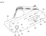
- FIG. 8 is a partial bottom perspective view corresponding to FIG. 7 in a state in which two core bits are omitted.
- FIG. 9 is a top view showing a state in which a moving plate is coupled to a fixing plate after moving with respect to the fixing plate from a state of FIG. 7 .
- the two-hole core drilling machine which is designated by reference numeral "500" includes a base 510 fixed to a structure to be drilled, a stand 520 vertically coupled to the base 510 and formed with a rack 522 at one side surface thereof, a vertically reciprocating carriage 530 provided with a pinion engaged with the rack 522 and vertically reciprocably mounted to the stand 520, a motor 540 coupled to one side surface of the carriage 530, a fixing plate 550 coupled to one side of a lower portion of the carriage 530, to rotatably support a drive shaft 542 of the motor 540, a pivoting plate 560 fastened to the fixing plate 550 under the condition that a pivot angle of the pivoting plate 560 is changed, and a moving plate 580 fastened to the pivoting plate 560 under the condition that a distance of the moving plate 580 from the fixing plate 550 is varied, and provided with a driven shaft 544 rotatably mounted thereto.
- the two-hole core drilling machine 500 also includes a drive force transmission (for example, a gear train) (in the following description, referred to as the "gear train" for convenience of description) 570 coupled between the drive shaft 542 and the driven shaft 544, to transmit rotation force of the drive shaft 542 to the driven shaft 544, a first core bit 590 coupled to the drive shaft 542, and a second core bit 590 coupled to the driven shaft 544.
- a drive force transmission for example, a gear train
- the driven shaft 544 to transmit rotation force of the drive shaft 542 to the driven shaft 544
- first core bit 590 coupled to the drive shaft 542
- second core bit 590 coupled to the driven shaft 544.
- the base 510 and the stand 520 may be collectively referred to as a "body”.
- the two-hole core drilling machine 500 is a core drilling machine configured to drill a hole into a horizontal bottom, a wall, or an inclined or curved surface having various shapes in a concrete structure.
- the base 510 may be provided with at least one pair of anchor bolts 512 and, as such, may be fixed to a surface of a structure.
- the base 510 may be provided with at least one pair of wheels 514 and, as such, the entirety of the drilling machine 500 may be easily movable.
- the stand 520 is vertically coupled to the base 510.
- the stand 520 may be formed to have a rectangular column shape.
- a connecting frame 516 may be coupled between a middle portion of the stand 520 and the base 510, to support the stand 520 with respect to the base 510.
- the rack 522 may be formed at one side surface of the stand 520, to vertically reciprocate the carriage 530 mounted to the stand 520.
- the carriage 530 may be provided therein with the pinion (not shown) engaged with the rack 522 and, as such, may be vertically reciprocably mounted to the stand 520.
- the carriage 530 may be provided with a lever 535 configured to rotate the pinion. Accordingly, upon operating the drilling machine 500, the operator may rotate the lever 535, thereby vertically reciprocating the carriage 530.
- guide grooves 524 may be formed at opposite side surfaces of the stand 520, respectively, to guide and support vertical reciprocation of the carriage 530.
- the motor 540 may be coupled to an upper portion of one side surface of the carriage 530, and the fixing plate 550 may be coupled to a lower portion of the side surface of the carriage 530.
- the motor 540 may be an electric motor, and the drive shaft 542 thereof may be rotatably supported by a bearing (not shown) mounted to the fixing plate 550.
- the pivoting plate 560 may be mounted to a lower surface of the fixing plate 550 such that the pivoting plate 560 is pivotable about the drive shaft 542.
- the pivoting plate 560 may be fixed to the fixing plate 550 by fasteners 554 under the condition that a pivot angle of the pivot plate 560 is changed.
- the moving plate 580 may be firmly fastened to the pivoting plate 560 under the condition that a relative position of the moving plate 580 with respect to the pivoting plate 560 is varied, in order to vary a distance between the moving plate 580 and the fixing plate 550.
- the driven shaft 544 may be rotatably mounted at a through hole formed at a center of the moving plate 580.
- the gear train 570 is coupled between the drive shaft 542 and the driven shaft 544, to transmit rotation force of the drive shaft 542 to the driven shaft 544.
- the gear train 570 may be constituted by two link brackets and five gears. A concrete configuration of the gear train 570 will be described later.
- a drive gear 575 may be coupled to the drive shaft 542, and a driven gear 579 may be coupled to the driven shaft 544, and, as such, the motor 540 may simultaneously rotate the drive shaft 542 and the driven shaft 544.
- the driven shaft 544 may be disposed to pass through a shaft hole 564 formed through a central portion of the pivoting plate 560 at one side of the pivoting plate 560 in the form of a large slot.
- the first core bit 590 is coupled to a lower end of the drive shaft 542, and the second core bit 590 is coupled to a lower end of the driven shaft 544.
- the first core bit 590 and the second core bit 590 may have the same size. However, two core bits having various sizes may be coupled to the drive shaft 542 and the driven shaft 544, respectively.
- the first core bit 590 and the second core bit 590 may be fixed in a state in which pivot angle positions of the first core bit 590 and the second core bit 590 with respect to the base 510 and a relative distance between the first core bit 590 and the second core bit 590 are adjusted.
- the two-hole core drilling machine 500 may simultaneously drill two holes in a state in which a relative pivot angle and a relative distance between the two holes is appropriately adjusted.
- the fixing plate 550 may be formed to take the form of a rectangular plate having an arc shape at one side thereof. Linear sides of the fixing plate 550 may be coupled to the carriage 530 and, as such, the fixing plate 550 may be vertically reciprocable together with the carriage 530.
- the fixing plate 550 may be provided with a plurality of fastening holes arranged on a circumference having a predetermined radius from the drive shaft 542.
- the pivoting plate 560 may be provided with a plurality of fastening holes 562 extending vertically through the pivoting plate 560.
- the plurality of fastening holes 562 of the pivoting plate 560 may be formed at positions corresponding to the plurality of fastening holes of the fixing plate 550, respectively.
- the pivoting plate 560 may be formed to take the form of a rectangular plate having an arc shape at both shorter sides thereof.
- the moving plate 580 may be formed to take the form of a substantially-square plate chamfered at four corners thereof.
- a guide groove 561 may be formed in a longitudinal direction at an upper surface of the pivoting plate 560, to guide movement of the moving plate 580 seated therein.
- a protrusion may be formed at one side of a lower surface of the moving plate 580 contacting the guide groove 561.
- a groove (not shown), which engages with the protrusion, thereby allowing stable movement of the moving plate 580 while preventing separation of the moving plate 580, may be formed at the pivoting plate 560.
- pivoting plate 560 It may be possible to fix the pivoting plate 560 at a predetermined pivot position with respect to the fixing plate 550 by fastening the fasteners 554 through the plurality of fastening holes of the fixing plate 550 and the plurality of fastening holes 562 of the pivoting plate 560.
- eight fastening holes 562 are formed at the pivoting plate 560, as shown in FIG. 8 , it may be possible to firmly fasten fasteners 554 at positions where the pivoting plate 560 is pivoted with respect to the fixing plate 550 through 45°, respectively.
- the pivoting plate 560 may be provided with a plurality of slits 566 formed lengthily in a longitudinal direction
- the moving plate 580 may be provided with a plurality of fastening holes 582 extending vertically through the moving plate 580.
- three pairs of slits 566 may be formed at the pivoting plate 560
- three pairs of fastening holes 582 may be formed at the moving plate 580.
- the gear train 570 may include a first link bracket 571 pivotably mounted to the drive shaft 542, a second link bracket 572 pivotably connected, at one end thereof, to the first link bracket 571 while being pivotably mounted, at the other end thereof, to the driven shaft 544, the drive gear 575 coupled to the drive shaft 542, to be rotatable by the drive shaft 542, a first intermediate gear 576 mounted to the first link bracket 571 while engaging with the drive gear 575, a second intermediate gear 577 mounted to connection portions of the first link bracket 571 and the second link bracket 572 while engaging with the first intermediate gear 576, a third intermediate gear 578 mounted to the second link bracket 572 while engaging with the second intermediate gear 577, and the driven gear 579 coupled to the driven shaft 544 while engaging with the third intermediate gear 578, to be rotatable by the third intermediate gear 578.
- the first link bracket 571 may be disposed over and under three gears, and rotation shafts of the three gears may be mounted to the first link bracket 571.
- the first link bracket 571 may be formed to take the form of a pair of rectangular plates each having a semicircular shape at both shorter sides thereof. One side of the first link bracket 571 may be pivotably mounted to the drive shaft 541.
- the second link bracket 572 may also be formed to take the form of a pair of rectangular plates each having a semicircular shape at both shorter sides thereof. Rotation shafts of three gears may be mounted between the pair of second link brackets 572. Other-side portions of the pair of first link brackets 571 and one-side portions of the pair of second link brackets 572 may be formed to have a thickness reduced by half, thereby forming steps, respectively, and, as such, may be interconnected to be pivotable with respect to each other about a rotation shaft of the second intermediate gear 577.
- the drive gear 575 may be coupled to the drive shaft 542 rotated by the motor 540 and, as such, may rotate together with the drive shaft 542.
- the first intermediate gear 576 may be rotatably mounted between middle portions of the pair of first link brackets 571, and may engage with the drive gear 575 and, as such, may be rotated.
- the second intermediate gear 577 may be mounted between the connection portions of the first link bracket 571 and the second link bracket 572, and may engage with the first intermediate gear 576 and, as such, may be rotated.
- the third intermediate gear 578 may be mounted between the middle portions of the pair of second link brackets 572, and may engage with the second intermediate gear 577 and, as such, may be rotated.
- the driven gear 579 may be coupled to the driven shaft 544 mounted to the other-side portions of the pair of second link brackets 572, and may engage with the third intermediate gear 578 and, as such, may be rotated.
- the moving plate 580 may be fixed at a position farther from the fixing plate 550, as compared to the case of FIG. 7 .
- the angle between the first link bracket 571 and the second link bracket 572 may be fixed in a slightly diverged state.
- water supply hoses 595 may be connected to a side surface of a middle portion of the drive shaft 542 and a side surface of an upper portion of the driven shaft 544, respectively, to supply cooling water. That is, the core drilling machine 500 according to the exemplary embodiment of the present invention may be a wet core drilling machine configured to drill holes by simultaneously rotating core bits while supplying water.
- the water supply hoses 595 are detachably connected to a water supply pipe provided with a valve, and may be connected in parallel in order to supply water along channels communicating with interiors of respective core bits 590 after passing through interiors of the drive shaft 542 and the driven shaft 544. Since the distance between the drive shaft 542 and the driven shaft 544 is variable, the water supply hoses 595 connected between the drive shaft 542 and the driven shaft 544 may be formed of a flexible material and may be connected while having a sufficient length.
- the relative pivot angle between the two core bits and the distance between the two core bits may be adjusted and, as such, it may be possible to easily simultaneously drill two holes while appropriately adjusting the distance between the two holes to be drilled within a predetermined range.
- the two-hole core drilling machine is industrially applicable for pulling-down and repair of a construction in a construction site.
Landscapes
- Engineering & Computer Science (AREA)
- Mechanical Engineering (AREA)
- Mining & Mineral Resources (AREA)
- Processing Of Stones Or Stones Resemblance Materials (AREA)
- Drilling And Boring (AREA)
Claims (15)
- Zweiloch-Kernbohrmaschine (100), die Folgendes aufweist:einen Körper;einen vertikal hin und her beweglichen Schlitten (130), der vertikal hin und her beweglich an dem Körper angebracht ist;eine Befestigungsplatte (140), die mit der einen Seitenfläche des Schlittens (130) gekoppelt ist, um eine Antriebswelle (152) eines Motors (150) drehbar abzustützen;wobei die Zweiloch-Kernbohrmaschine (100) dadurch gekennzeichnet ist, dass sie Folgendes aufweist:eine Schwenkplatte (160), die an der Befestigungsplatte (140) befestigt ist, wobei ein Schwenkwinkel der Schwenkplatte (160) geändert werden kann;eine bewegliche Platte (170), die an der Schwenkplatte (160) befestigt ist, wobei eine Länge der beweglichen Platte (170) von der Schwenkplatte (160) variabel ist;einen Riemen oder eine Kette (175), der/die zwischen einer mit der Antriebswelle gekoppelten Antriebsscheibe (154) und einer mit einer angetriebenen Welle (172) gekoppelten angetriebenen Scheibe (171) angebracht ist, die an der beweglichen Platte (170) drehbar angebracht ist;einen ersten Kernbohrer (190), der mit der Antriebswelle (152) gekoppelt ist; undeinen zweiten Kernbohrer (190), der mit der angetriebenen Welle (172) gekoppelt ist.
- Zweiloch-Kernbohrmaschine (100) nach Anspruch 1, wobei:die Befestigungsplatte (140) einen Schwenkführungsschlitz (145) aufweist, der durch die Befestigungsplatte (140) hindurch ausgebildet ist und eine Bogenform aufweist;die Schwenkplatte (160) eine Mehrzahl von Befestigungsöffnungen (162) aufweist, die sich vertikal durch die Schwenkplatte (160) hindurch erstreckend ausgebildet sind; unddie Schwenkplatte (160) durch Befestigungselemente (168), die an der Mehrzahl von Befestigungsöffnungen (162) und dem Schwenkführungsschlitz (145) befestigt sind, in einer vorbestimmten Schwenkposition in Bezug auf die Befestigungsplatte (140) festgelegt ist.
- Zweiloch-Kernbohrmaschine (100) nach Anspruch 1, wobei:die Schwenkplatte (160) einen in Längsrichtung länglich ausgebildeten Bewegungsführungsschlitz aufweist;die bewegliche Platte (170) eine Mehrzahl von Befestigungsöffnungen (177) aufweist, die sich vertikal durch die bewegliche Platte (170) hindurch erstreckend ausgebildet sind; unddie bewegliche Platte (170) durch Befestigungselemente (178), die an der Mehrzahl von Befestigungsöffnungen (177) und dem Bewegungsführungsschlitz befestigt sind, in einer vorbestimmten Position in Längsrichtung in Bezug auf die Schwenkplatte (160) festgelegt ist.
- Zweiloch-Kernbohrmaschine (100) nach Anspruch 3,
wobei die bewegliche Platte (170) außerdem eine Spannrolle (180) aufweist, die dazu ausgebildet ist, fixiert zu werden, nachdem sich eine Drehwelle der Spannrolle (180) in Richtung auf den Riemen oder die Kette (175) bewegt, die entsprechend einer Bewegung der beweglichen Platte (170) gelockert wird, wodurch Spannung auf den Riemen oder die Kette (175) ausgeübt wird. - Zweiloch-Kernbohrmaschine (100) nach Anspruch 3,
wobei Wasserzuführschläuche (195) mit unteren Bereichen der Antriebswelle (152) bzw. der angetriebenen Welle (172) verbunden sind, um Kühlwasser zuzuführen. - Zweiloch-Kernbohrmaschine (100) nach Anspruch 1, wobei:
der Körper aufweist:eine Basis (100), die an einer zu bohrenden Struktur festgelegt ist; undeinen Ständer (120), der mit der Basis (110) vertikal gekoppelt ist und an seiner einen Seitenfläche mit einer Verzahnung versehen ist; undder Schlitten (130) mit einem Ritzel ausgestattet ist, das mit der Verzahnung (122) in Eingriff steht, sowie vertikal hin und her beweglich an dem Ständer (120) angebracht ist. - Zweiloch-Kernbohrmaschine (100) nach Anspruch 6,
wobei die Verzahnung (122) eine Zahnstange umfasst. - Zweiloch-Kernbohrmaschine (500), die Folgendes aufweist:einen Körper;einen vertikal hin und her beweglichen Schlitten (530), der vertikal hin und her beweglich an dem Körper angebracht ist;eine Befestigungsplatte (550), die mit einer Seite des Schlittens (530) gekoppelt ist, um eine Antriebswelle (542) eines Motors (540) drehbar abzustützen;wobei die Zweiloch-Kernbohrmaschine (500) dadurch gekennzeichnet ist, dass sie Folgendes aufweist:eine Schwenkplatte (560), die an der Befestigungsplatte (550) befestigt ist, wobei ein Schwenkwinkel der Schwenkplatte (560) geändert werden kann;eine bewegliche Platte (580), die an der Schwenkplatte (560) befestigt ist, wobei ein Abstand der beweglichen Platte (580) von der Befestigungsplatte (550) variabel ist und eine angetriebene Welle (544) an der beweglichen Platte (580) drehbar angebracht ist;einen zwischen die Antriebswelle (542) und die angetriebene Welle (544) geschalteten Getriebezug (570) zum Übertragen von Drehkraft der Antriebswelle (542) auf die angetriebene Welle (544);einen ersten Kernbohrer (590), der mit der Antriebswelle (542) gekoppelt ist; undeinen zweiten Kernbohrer (590), der mit der angetriebenen Welle (544) gekoppelt ist.
- Zweiloch-Kernbohrmaschine (500) nach Anspruch 8, wobei:die Befestigungsplatte (550) eine Mehrzahl von Befestigungsöffnungen aufweist, die auf einem Umfang mit einem vorbestimmten Radius von der Antriebswelle (542) angeordnet sind;die Schwenkplatte (560) eine Mehrzahl von Befestigungsöffnungen (562) aufweist, die sich vertikal durch die Schwenkplatte (560) hindurch erstrecken; unddie Schwenkplatte (560) durch Befestigungselemente (554), die durch die Mehrzahl von Befestigungsöffnungen der Befestigungsplatte (550) und die Mehrzahl von Befestigungsöffnungen (562) der Schwenkplatte (560) hindurch befestigt sind, in einer vorbestimmten Schwenkposition in Bezug auf die Befestigungsplatte (550) festgelegt ist.
- Zweiloch-Kernbohrmaschine (500) nach Anspruch 9, wobei:die Schwenkplatte (560) eine Mehrzahl von Schlitzen aufweist, die in Längsrichtung ausgebildet sind;die bewegliche Platte (580) eine Mehrzahl von Befestigungsöffnungen (582) aufweist, die sich vertikal durch die bewegliche Platte (580) hindurch erstreckend ausgebildet sind; unddie bewegliche Platte (580) durch Befestigungselemente (568), die an der Mehrzahl von Befestigungsöffnungen (582) und der Mehrzahl von Schlitzen (566) befestigt sind, in einer vorbestimmten Position in Längsrichtung in Bezug auf die Schwenkplatte (560) festgelegt ist.
- Zweiloch-Kernbohrmaschine (500) nach Anspruch 8,
wobei der Getriebezug (570) aufweist:eine erste Verbindungshalterung (571), die an der Antriebswelle (542) schwenkbar angebracht ist;eine zweite Verbindungshalterung (572), die an ihrem einen Ende mit der ersten Verbindungshalterung (571) schwenkbar verbunden ist, während sie an ihrem anderen Ende an der angetriebenen Welle (544) schwenkbar angebracht ist;ein Antriebszahnrad (575), das mit der Antriebswelle (542) gekoppelt ist, so dass es durch die Antriebswelle (542) gedreht werden kann;ein erstes Zwischenzahnrad (576), das an der ersten Verbindungshalterung (571) angebracht ist und mit dem Antriebszahnrad (575) in Eingriff steht;ein zweites Zwischenzahnrad (577), das an Verbindungsbereichen der ersten Verbindungshalterung (571) und der zweiten Verbindungshalterung (572) angebracht ist und mit dem ersten Zwischenzahnrad (576) in Eingriff steht;ein drittes Zwischenzahnrad (578), das an der zweiten Verbindungshalterung (572) angebracht ist und mit dem zweiten Zwischenzahnrad (577) in Eingriff steht; undein angetriebenes Zahnrad (570), das mit der angetriebenen Welle (544) gekoppelt ist und mit dem dritten Zwischenzahnrad (578) in Eingriff steht, so dass es durch das dritte Zwischenzahnrad (572) gedreht werden kann. - Zweiloch-Kernbohrmaschine (500) nach Anspruch 10,
wobei Wasserzuführschläuche (595) mit einem mittleren Bereich der Antriebswelle (542) bzw. einem oberen Bereich der angetriebenen Welle (544) verbunden sind, um Kühlwasser zuzuführen. - Zweiloch-Kernbohrmaschine (500) nach Anspruch 8, wobei:
der Körper aufweist:eine Basis (510), die an einer zu bohrenden Struktur festgelegt ist; undeinen Ständer (520), der mit der Basis (510) vertikal gekoppelt ist und an seiner einen Seitenfläche mit einer Verzahnung (522) ausgebildet ist. - Zweiloch-Kernbohrmaschine (500) nach Anspruch 8,
wobei eine Führungsnut (561), die zum Führen der Bewegung der beweglichen Platte (580) ausgebildet ist, an einer oberen Oberfläche der Schwenkplatte (560) gebildet ist. - Zweiloch-Kernbohrmaschine (500) nach Anspruch 14,
wobei an einer Seitenfläche der beweglichen Platte (580) ein Vorsprung ausgebildet ist und eine mit dem Vorsprung in Eingriff stehende Nut in Längsrichtung in der Schwenkplatte (560) ausgebildet ist, um eine Trennung der beweglichen Platte (580) zu verhindern.
Applications Claiming Priority (3)
| Application Number | Priority Date | Filing Date | Title |
|---|---|---|---|
| KR1020210101219A KR102360421B1 (ko) | 2021-08-02 | 2021-08-02 | 2구 천공 코어드릴 장치 |
| KR1020210152711A KR102370202B1 (ko) | 2021-11-09 | 2021-11-09 | 개선된 2구 천공 코어 드릴장치 |
| PCT/KR2022/010838 WO2023013942A1 (ko) | 2021-08-02 | 2022-07-22 | 2구 천공 코어드릴 장치 |
Publications (4)
| Publication Number | Publication Date |
|---|---|
| EP4151380A1 EP4151380A1 (de) | 2023-03-22 |
| EP4151380A4 EP4151380A4 (de) | 2023-12-20 |
| EP4151380B1 true EP4151380B1 (de) | 2025-03-19 |
| EP4151380C0 EP4151380C0 (de) | 2025-03-19 |
Family
ID=84887575
Family Applications (1)
| Application Number | Title | Priority Date | Filing Date |
|---|---|---|---|
| EP22808926.4A Active EP4151380B1 (de) | 2021-08-02 | 2022-07-22 | Zweiloch-kernbohrmaschine |
Country Status (4)
| Country | Link |
|---|---|
| US (1) | US20250073953A1 (de) |
| EP (1) | EP4151380B1 (de) |
| JP (1) | JP7769423B2 (de) |
| WO (1) | WO2023013942A1 (de) |
Families Citing this family (5)
| Publication number | Priority date | Publication date | Assignee | Title |
|---|---|---|---|---|
| KR102639930B1 (ko) * | 2021-11-29 | 2024-02-23 | 주식회사 이건 | 4구천공 코어드릴 장치 |
| CN116214736B (zh) * | 2023-04-06 | 2023-09-26 | 李汉宇 | 一种建筑施工钻孔装置 |
| CN116652612B (zh) * | 2023-07-26 | 2024-03-08 | 吉安裕泓科技有限公司 | 一种用于货箱锁止销孔的加工设备 |
| CN116984944A (zh) * | 2023-09-21 | 2023-11-03 | 邢台军华机械科技有限公司 | 一种手自动一体式穿孔机 |
| CN119216633B (zh) * | 2024-12-04 | 2025-03-28 | 山建大工程技术(山东)有限公司 | 一种消防施工用管道切割开孔设备 |
Family Cites Families (33)
| Publication number | Priority date | Publication date | Assignee | Title |
|---|---|---|---|---|
| US1083696A (en) * | 1912-11-21 | 1914-01-06 | Arne T Nelson | Adjustable multiple-spindle head for drill-presses. |
| FR642926A (fr) * | 1927-10-24 | 1928-09-06 | Appareil pour percer plusieurs trous à la fois | |
| US2499657A (en) * | 1947-05-26 | 1950-03-07 | Theodore G Linderme | Drill head |
| US2884818A (en) * | 1955-05-31 | 1959-05-05 | Us Drill Head Co | Drill head |
| DE1115098B (de) * | 1958-01-04 | 1961-10-12 | Siemens Ag | Einrichtung zum Einstellen des Abstandes der gemeinsam angetriebenen Bohrspindeln eines zweispindeligen Bohrkopfes |
| FR1205667A (fr) * | 1958-06-27 | 1960-02-04 | Boîte à broches multiples à entr'axes réglables pour machines à percer ou analoges | |
| US3215005A (en) * | 1964-11-13 | 1965-11-02 | Miyakawa Eizi | Multiple spindle drilling machine with adjustable spindles |
| FR2044897A5 (de) * | 1969-05-13 | 1971-02-26 | Miyagawa Eizi | |
| JPS486693U (de) * | 1971-06-05 | 1973-01-25 | ||
| DE2701516A1 (de) * | 1977-01-15 | 1978-07-20 | Scheer & Cie C F | Bohrkopf fuer mehrspindel-bohrmaschine |
| JPS56126305U (de) * | 1980-02-26 | 1981-09-25 | ||
| AT377221B (de) * | 1982-12-23 | 1985-02-25 | Ruml Walter | Zusatzgeraet fuer handoberfraesen zum einbohren von moebeltuerbaendern |
| US4517857A (en) * | 1983-02-16 | 1985-05-21 | Miyakawa Industry Co., Ltd. | Gear interference preventing mechanism in multi-spindle head attachment |
| JPS6029607U (ja) * | 1983-08-05 | 1985-02-28 | 株式会社 大勝機工工事 | コンクリ−ト材等の穿孔装置 |
| FR2568802B1 (fr) * | 1984-08-07 | 1986-09-12 | Renault | Tete multibroches pour machine-outil, notamment pour ensemble d'usinage a tetes interchangeables |
| JPS62152605A (ja) * | 1985-12-27 | 1987-07-07 | Mitsubishi Heavy Ind Ltd | 多軸穴明装置 |
| FR2655896A1 (fr) * | 1989-12-18 | 1991-06-21 | Roux Jacques | Plateau multibroche d'usinage de configuration variable. |
| JP2761996B2 (ja) * | 1992-03-30 | 1998-06-04 | 株式会社ダイフクテクノサービス | 床面穿孔装置 |
| NL9301721A (nl) * | 1993-10-06 | 1995-05-01 | Adamas Nederland B V | Boormachine en werkwijze voor het gebruik daarvan. |
| JP2001105211A (ja) * | 1999-10-01 | 2001-04-17 | Shibuya:Kk | 二軸可変ピッチコアドリルの構造 |
| KR200278379Y1 (ko) * | 2002-02-23 | 2002-06-20 | 최순봉 | 안경형판 제작용 다목적 드릴공구 |
| US7059812B2 (en) * | 2003-01-13 | 2006-06-13 | Mcfarlane Leslie Andrew | Portable, hand-held multiple bit drill |
| CH697003A5 (fr) * | 2003-02-25 | 2008-03-14 | Gianni De Donno | Machine de perçage à main et à outils multiples. |
| DE102004033361A1 (de) * | 2004-07-02 | 2006-01-19 | C. & E. Fein Gmbh | Bohrmaschine, insbesondere Kernlochbohrmaschine |
| JP4806458B2 (ja) * | 2009-06-08 | 2011-11-02 | 株式会社呉英製作所 | 工具ガイド機構および深穴明機 |
| KR101302141B1 (ko) * | 2013-05-15 | 2013-08-30 | (주)원플랜트 | 축간 거리 조절이 자유로운 다축드릴장치 |
| CN103909285A (zh) * | 2014-04-08 | 2014-07-09 | 新乡市欧亿石油机械有限公司 | 数控液压排钻 |
| CN104625144B (zh) * | 2015-01-13 | 2017-04-12 | 苏州市职业大学 | 一种三轴中心距同时可调打孔机 |
| CN105234447A (zh) * | 2015-10-18 | 2016-01-13 | 滁州开关电器科技有限公司 | 自动化钻床 |
| CN112475352A (zh) * | 2020-12-21 | 2021-03-12 | 北京环都拓普空调有限公司 | 一种间距可调式多孔钻 |
| KR102360421B1 (ko) * | 2021-08-02 | 2022-02-09 | 주식회사 이건 | 2구 천공 코어드릴 장치 |
| KR102370202B1 (ko) * | 2021-11-09 | 2022-03-04 | 주식회사 이건 | 개선된 2구 천공 코어 드릴장치 |
| KR102639930B1 (ko) * | 2021-11-29 | 2024-02-23 | 주식회사 이건 | 4구천공 코어드릴 장치 |
-
2022
- 2022-07-22 WO PCT/KR2022/010838 patent/WO2023013942A1/ko not_active Ceased
- 2022-07-22 JP JP2024506150A patent/JP7769423B2/ja active Active
- 2022-07-22 EP EP22808926.4A patent/EP4151380B1/de active Active
- 2022-07-22 US US17/928,883 patent/US20250073953A1/en active Pending
Also Published As
| Publication number | Publication date |
|---|---|
| JP2024530150A (ja) | 2024-08-16 |
| JP7769423B2 (ja) | 2025-11-13 |
| US20250073953A1 (en) | 2025-03-06 |
| EP4151380A4 (de) | 2023-12-20 |
| WO2023013942A1 (ko) | 2023-02-09 |
| EP4151380A1 (de) | 2023-03-22 |
| EP4151380C0 (de) | 2025-03-19 |
Similar Documents
| Publication | Publication Date | Title |
|---|---|---|
| EP4151380B1 (de) | Zweiloch-kernbohrmaschine | |
| US20240286205A1 (en) | Multi-Hole Core Drilling Machine | |
| CN117794714A (zh) | 两孔式取芯钻进机器 | |
| EP4186622A1 (de) | Vierloch-kernbohrmaschine | |
| KR102360421B1 (ko) | 2구 천공 코어드릴 장치 | |
| EP1207028B1 (de) | Bohrvorrichtung für Platten | |
| US20140331507A1 (en) | Novel jig saw | |
| KR101346460B1 (ko) | 턴 및 틸팅 동작이 선택 실행되는 수직형 갠트리 그립퍼 장치 | |
| CN108296517B (zh) | 一种板材多位钻孔设备 | |
| KR20140055622A (ko) | 파이프 절단 장치용 보조 장치 | |
| CN211645871U (zh) | 推料装置及具有其的整平机 | |
| CN112605419A (zh) | 一种高精度双向钻孔设备的组装方法 | |
| KR20180135319A (ko) | 점자인쇄모듈 | |
| KR20220056383A (ko) | 회전 작업대 | |
| KR100611308B1 (ko) | 강관말뚝 절단기 | |
| CN212385095U (zh) | 一种用于棒材机械加工的自动进料装置 | |
| KR100333509B1 (ko) | 교량 평탄화 작업기계 | |
| CN223367925U (zh) | 一种卷板机加工用辅助装置 | |
| KR20090018548A (ko) | 다축 태핑머신 | |
| CN119244696B (zh) | 一种激光加工机 | |
| CN222154681U (zh) | 一种缓冲托辊轴的加工打孔用定位工装 | |
| JPH02145205A (ja) | 形鋼穿孔機 | |
| CN223265237U (zh) | 一种金属管材加工用夹持装置 | |
| KR910007278B1 (ko) | 이동식 띠톱 절단기 | |
| CN118239418A (zh) | 一种地铁隧道机电管道快速安装设备、安装系统 |
Legal Events
| Date | Code | Title | Description |
|---|---|---|---|
| STAA | Information on the status of an ep patent application or granted ep patent |
Free format text: STATUS: UNKNOWN |
|
| STAA | Information on the status of an ep patent application or granted ep patent |
Free format text: STATUS: THE INTERNATIONAL PUBLICATION HAS BEEN MADE |
|
| PUAI | Public reference made under article 153(3) epc to a published international application that has entered the european phase |
Free format text: ORIGINAL CODE: 0009012 |
|
| STAA | Information on the status of an ep patent application or granted ep patent |
Free format text: STATUS: REQUEST FOR EXAMINATION WAS MADE |
|
| 17P | Request for examination filed |
Effective date: 20221130 |
|
| AK | Designated contracting states |
Kind code of ref document: A1 Designated state(s): AL AT BE BG CH CY CZ DE DK EE ES FI FR GB GR HR HU IE IS IT LI LT LU LV MC MK MT NL NO PL PT RO RS SE SI SK SM TR |
|
| REG | Reference to a national code |
Ref country code: DE Ref legal event code: R079 Free format text: PREVIOUS MAIN CLASS: B28D0001140000 Ipc: B28D0001040000 Ref country code: DE Ref legal event code: R079 Ref document number: 602022012062 Country of ref document: DE Free format text: PREVIOUS MAIN CLASS: B28D0001140000 Ipc: B28D0001040000 |
|
| A4 | Supplementary search report drawn up and despatched |
Effective date: 20231120 |
|
| RIC1 | Information provided on ipc code assigned before grant |
Ipc: B28D 7/02 20060101ALN20231114BHEP Ipc: B23B 51/04 20060101ALI20231114BHEP Ipc: B23B 39/16 20060101ALI20231114BHEP Ipc: B28D 1/04 20060101AFI20231114BHEP |
|
| GRAP | Despatch of communication of intention to grant a patent |
Free format text: ORIGINAL CODE: EPIDOSNIGR1 |
|
| STAA | Information on the status of an ep patent application or granted ep patent |
Free format text: STATUS: GRANT OF PATENT IS INTENDED |
|
| RIC1 | Information provided on ipc code assigned before grant |
Ipc: B28D 7/02 20060101ALN20240912BHEP Ipc: B23B 51/04 20060101ALI20240912BHEP Ipc: B23B 39/16 20060101ALI20240912BHEP Ipc: B28D 1/04 20060101AFI20240912BHEP |
|
| DAV | Request for validation of the european patent (deleted) | ||
| DAX | Request for extension of the european patent (deleted) | ||
| INTG | Intention to grant announced |
Effective date: 20241009 |
|
| GRAS | Grant fee paid |
Free format text: ORIGINAL CODE: EPIDOSNIGR3 |
|
| GRAA | (expected) grant |
Free format text: ORIGINAL CODE: 0009210 |
|
| STAA | Information on the status of an ep patent application or granted ep patent |
Free format text: STATUS: THE PATENT HAS BEEN GRANTED |
|
| AK | Designated contracting states |
Kind code of ref document: B1 Designated state(s): AL AT BE BG CH CY CZ DE DK EE ES FI FR GB GR HR HU IE IS IT LI LT LU LV MC MK MT NL NO PL PT RO RS SE SI SK SM TR |
|
| REG | Reference to a national code |
Ref country code: GB Ref legal event code: FG4D |
|
| REG | Reference to a national code |
Ref country code: CH Ref legal event code: EP |
|
| REG | Reference to a national code |
Ref country code: DE Ref legal event code: R096 Ref document number: 602022012062 Country of ref document: DE |
|
| REG | Reference to a national code |
Ref country code: IE Ref legal event code: FG4D |
|
| U01 | Request for unitary effect filed |
Effective date: 20250417 |
|
| U07 | Unitary effect registered |
Designated state(s): AT BE BG DE DK EE FI FR IT LT LU LV MT NL PT RO SE SI Effective date: 20250424 |
|
| PG25 | Lapsed in a contracting state [announced via postgrant information from national office to epo] |
Ref country code: RS Free format text: LAPSE BECAUSE OF FAILURE TO SUBMIT A TRANSLATION OF THE DESCRIPTION OR TO PAY THE FEE WITHIN THE PRESCRIBED TIME-LIMIT Effective date: 20250619 |
|
| PG25 | Lapsed in a contracting state [announced via postgrant information from national office to epo] |
Ref country code: NO Free format text: LAPSE BECAUSE OF FAILURE TO SUBMIT A TRANSLATION OF THE DESCRIPTION OR TO PAY THE FEE WITHIN THE PRESCRIBED TIME-LIMIT Effective date: 20250619 |
|
| PG25 | Lapsed in a contracting state [announced via postgrant information from national office to epo] |
Ref country code: HR Free format text: LAPSE BECAUSE OF FAILURE TO SUBMIT A TRANSLATION OF THE DESCRIPTION OR TO PAY THE FEE WITHIN THE PRESCRIBED TIME-LIMIT Effective date: 20250319 |
|
| PG25 | Lapsed in a contracting state [announced via postgrant information from national office to epo] |
Ref country code: GR Free format text: LAPSE BECAUSE OF FAILURE TO SUBMIT A TRANSLATION OF THE DESCRIPTION OR TO PAY THE FEE WITHIN THE PRESCRIBED TIME-LIMIT Effective date: 20250620 |
|
| U21 | Renewal fee for the european patent with unitary effect paid with additional fee |
Year of fee payment: 4 Effective date: 20250812 |
|
| PG25 | Lapsed in a contracting state [announced via postgrant information from national office to epo] |
Ref country code: SM Free format text: LAPSE BECAUSE OF FAILURE TO SUBMIT A TRANSLATION OF THE DESCRIPTION OR TO PAY THE FEE WITHIN THE PRESCRIBED TIME-LIMIT Effective date: 20250319 |
|
| PG25 | Lapsed in a contracting state [announced via postgrant information from national office to epo] |
Ref country code: ES Free format text: LAPSE BECAUSE OF FAILURE TO SUBMIT A TRANSLATION OF THE DESCRIPTION OR TO PAY THE FEE WITHIN THE PRESCRIBED TIME-LIMIT Effective date: 20250319 |
|
| PG25 | Lapsed in a contracting state [announced via postgrant information from national office to epo] |
Ref country code: PL Free format text: LAPSE BECAUSE OF FAILURE TO SUBMIT A TRANSLATION OF THE DESCRIPTION OR TO PAY THE FEE WITHIN THE PRESCRIBED TIME-LIMIT Effective date: 20250319 |
|
| PG25 | Lapsed in a contracting state [announced via postgrant information from national office to epo] |
Ref country code: CZ Free format text: LAPSE BECAUSE OF FAILURE TO SUBMIT A TRANSLATION OF THE DESCRIPTION OR TO PAY THE FEE WITHIN THE PRESCRIBED TIME-LIMIT Effective date: 20250319 |
|
| PG25 | Lapsed in a contracting state [announced via postgrant information from national office to epo] |
Ref country code: SK Free format text: LAPSE BECAUSE OF FAILURE TO SUBMIT A TRANSLATION OF THE DESCRIPTION OR TO PAY THE FEE WITHIN THE PRESCRIBED TIME-LIMIT Effective date: 20250319 |
|
| PG25 | Lapsed in a contracting state [announced via postgrant information from national office to epo] |
Ref country code: IS Free format text: LAPSE BECAUSE OF FAILURE TO SUBMIT A TRANSLATION OF THE DESCRIPTION OR TO PAY THE FEE WITHIN THE PRESCRIBED TIME-LIMIT Effective date: 20250719 |
|
| PLBE | No opposition filed within time limit |
Free format text: ORIGINAL CODE: 0009261 |
|
| STAA | Information on the status of an ep patent application or granted ep patent |
Free format text: STATUS: NO OPPOSITION FILED WITHIN TIME LIMIT |
|
| REG | Reference to a national code |
Ref country code: CH Ref legal event code: L10 Free format text: ST27 STATUS EVENT CODE: U-0-0-L10-L00 (AS PROVIDED BY THE NATIONAL OFFICE) Effective date: 20260128 |