EP4145424B1 - Bewegungssimulator - Google Patents
Bewegungssimulator Download PDFInfo
- Publication number
- EP4145424B1 EP4145424B1 EP22184580.3A EP22184580A EP4145424B1 EP 4145424 B1 EP4145424 B1 EP 4145424B1 EP 22184580 A EP22184580 A EP 22184580A EP 4145424 B1 EP4145424 B1 EP 4145424B1
- Authority
- EP
- European Patent Office
- Prior art keywords
- motion
- platform
- base
- actuator
- carrying platform
- Prior art date
- Legal status (The legal status is an assumption and is not a legal conclusion. Google has not performed a legal analysis and makes no representation as to the accuracy of the status listed.)
- Active
Links
Images


Classifications
-
- G—PHYSICS
- G09—EDUCATION; CRYPTOGRAPHY; DISPLAY; ADVERTISING; SEALS
- G09B—EDUCATIONAL OR DEMONSTRATION APPLIANCES; APPLIANCES FOR TEACHING, OR COMMUNICATING WITH, THE BLIND, DEAF OR MUTE; MODELS; PLANETARIA; GLOBES; MAPS; DIAGRAMS
- G09B9/00—Simulators for teaching or training purposes
- G09B9/02—Simulators for teaching or training purposes for teaching control of vehicles or other craft
- G09B9/08—Simulators for teaching or training purposes for teaching control of vehicles or other craft for teaching control of aircraft, e.g. Link trainer
- G09B9/12—Motion systems for aircraft simulators
-
- A—HUMAN NECESSITIES
- A63—SPORTS; GAMES; AMUSEMENTS
- A63G—MERRY-GO-ROUNDS; SWINGS; ROCKING-HORSES; CHUTES; SWITCHBACKS; SIMILAR DEVICES FOR PUBLIC AMUSEMENT
- A63G31/00—Amusement arrangements
- A63G31/02—Amusement arrangements with moving substructures
-
- A—HUMAN NECESSITIES
- A47—FURNITURE; DOMESTIC ARTICLES OR APPLIANCES; COFFEE MILLS; SPICE MILLS; SUCTION CLEANERS IN GENERAL
- A47C—CHAIRS; SOFAS; BEDS
- A47C1/00—Chairs adapted for special purposes
-
- A—HUMAN NECESSITIES
- A63—SPORTS; GAMES; AMUSEMENTS
- A63G—MERRY-GO-ROUNDS; SWINGS; ROCKING-HORSES; CHUTES; SWITCHBACKS; SIMILAR DEVICES FOR PUBLIC AMUSEMENT
- A63G31/00—Amusement arrangements
- A63G31/16—Amusement arrangements creating illusions of travel
-
- G—PHYSICS
- G09—EDUCATION; CRYPTOGRAPHY; DISPLAY; ADVERTISING; SEALS
- G09B—EDUCATIONAL OR DEMONSTRATION APPLIANCES; APPLIANCES FOR TEACHING, OR COMMUNICATING WITH, THE BLIND, DEAF OR MUTE; MODELS; PLANETARIA; GLOBES; MAPS; DIAGRAMS
- G09B9/00—Simulators for teaching or training purposes
- G09B9/02—Simulators for teaching or training purposes for teaching control of vehicles or other craft
- G09B9/08—Simulators for teaching or training purposes for teaching control of vehicles or other craft for teaching control of aircraft, e.g. Link trainer
- G09B9/12—Motion systems for aircraft simulators
- G09B9/14—Motion systems for aircraft simulators controlled by fluid actuated piston or cylinder ram
Definitions
- the present invention is related to a motion simulator capable of simulating different motions with a simple structure.
- a motion simulator usually controls the movement of a seat so that a passenger on that seat is moved as well.
- the passenger may be tricked and believe that he is experiencing the motions within the visual content.
- Steward platform is a common motion simulation platform formed by six telescoping actuators. Although the Steward platform is capable of simulating various motions, the movement of one telescoping actuator is dependent on the movements of other telescoping actuators, making it difficult to control the movement of desired motions. Furthermore, the cost of the Steward platform is expensive for requiring six telescoping actuators.
- US 2003/0219701 A1 describes a flight simulating apparatus capable of directing combinations of elevation, yaw, roll, pitch and three-space accelerations to a cockpit.
- EP 2 623 169 A1 describes a conventional motion simulator.
- the present invention aims at providing a motion simulator capable of simulating different motions with a simple structure.
- the claimed motion simulator includes a base plate, a motion platform, a first actuator, a base, a second actuator and a carrying platform.
- the motion platform is arranged on the base plate and movably connected to the base plate.
- the first actuator is arranged on the motion platform and movably connected to the motion platform.
- the base has a base body extending in a length direction and a base extension surface extending in a width direction.
- the first actuator is movably connected to the base extension surface.
- the second actuator is movably arranged on the base.
- the carrying platform is movably connected to the second actuator, wherein through a connection relationship between the base and the second actuator arranged on the base, the first actuator performs a left-right movement of the carrying platform relative to the motion platform, and the second actuator performs the forward-backward movement of the carrying platform relative to the motion platform.
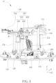
- FIG. 1 , FIG. 2 and FIG. 3 are schematic diagrams illustrating a motion simulator 10 according to an embodiment of the present invention.
- the motion simulator 10 includes a base plate 100, a carrying platform 110, a motion platform 120, a first actuator 130, a base 180 and a second actuator 140.
- a horizontal level of the base plate 100 is adjusted by a plurality of horizontal adjustment members, and the base plate 100 is arranged on a horizontal plane (the plane formed by the X-direction axis and the Z-direction axis).
- the motion platform 120 is arranged on the base plate 100 and is movably connected to the base plate 100.
- the carrying platform 110 is arranged above the motion platform 120 and apart from the motion platform 120.
- the carrying platform 110 includes a carrier arranged on the carrying platform 110.
- the carrier may include but is not limited to a chair.
- the carrying platform 110 includes a front end 112 and a rear end 114. When a passenger sits on the carrier, the passenger faces toward the direction of the front end 112 and the passenger's back is toward the rear end 114.
- the first actuator 130 (such as an electric cylinder) is arranged on the motion platform 120, and is movably connected to (e.g., pivotally connected to) the motion platform 120.
- the base 180 has a base body 182 extending in a length direction and a base extension surface 184 extending in a width direction.
- the first actuator 130 is movably connected to the base extension surface 184.
- the second actuator 140 (such as a screw rod sliding table) is movably arranged on the base 180, and the carrying platform 110 is movably connected to the second actuator 140.
- the first actuator 130 performs a left-right movement of the carrying platform 110 relative to the motion platform 120 through the connection relationship with the base 180 and the second actuator 140 arranged on the base 180, and the second actuator 140 performs the forward-backward movement of the carrying platform 110 relative to the motion platform 120.
- the left-right movement of the carrying platform 110 is tilting left, tilting right, moving left and/or moving right
- the frontward-backward movement of the carrying platform 110 is tilting forward, tilting back, moving forward and/or moving backward, but it is not limited thereto.
- the motion simulator 10 further includes a support assembly 150, a driving assembly 160 and a plurality of rotation wheels 170.
- the support assembly 150 is arranged on the motion platform 120 and is connected between the motion platform 120 and the base body 182.
- the support assembly 150 includes a first support rod 152 and a second support rod 154.
- the first support rod 152 is arranged on the motion platform 120, and has one end pivotally connected to the motion platform 120 and another end fixedly connected to the base body 182.
- the second support rod 154 is arranged on the motion platform 120, and has one end pivotally connected to the motion platform 120 and another end fixedly connected to the base body 182.
- the first support rod 152 and the second support rod 154 are arranged on opposite sides of the base extension surface 184, respectively.
- the driving assembly 160 is arranged on the base plate 100 (e.g., a center of the base plate 100), and configured to drive the motion platform 120 to rotate relative to the base plate 100 (e.g., clockwise rotation or counterclockwise rotation).
- the plurality of rotation wheels 170 are arranged on the motion platform 120 for assisting (or performing) the rotation of the motion platform 120.
- the rotation of the motion platform 120 may drive the carrying platform 110 arranged above the motion platform 120 to rotate, and drive the first actuator 130 and the second actuator 140 arranged on the motion platform 120 to rotate. Therefore, the driving assembly 160 and the plurality of rotation wheels 170 may provide a yaw motion for a passenger on the carrier.
- the rotation angle (of yaw motion) of the motion platform 120 is not limited by the overall structure. Compared with a general Stewart platform, the motion platform 120 may provide a more realistic 360-degree rotating motion.
- the first actuator 130 includes a basic portion 200 and an extension portion 220.
- the basic portion 200 is arranged on the motion platform 120.
- a bottom end of the basic portion 200 is movably connected (e.g., pivotally connected) to the motion platform 120.
- a bottom end of the extension portion 220 is connected to a top end of the basic portion 200, and a top end of the extension portion 220 is movably connected to the base extension surface 184.
- the extension portion 220 is extended or retracted to perform the left-right movement of the carrying platform 110.
- a pivot connection between the first support rod 152 and the motion platform 120 and a pivot connection between the second support rod 154 and the motion platform 120 are penetrated by a first rotation axis 240.
- the extension portion 220 of the first actuator 130 When the extension portion 220 of the first actuator 130 is extended or retracted, the base 180 and the carrying platform 110 perform the left-right movement based on the first rotation axis 240.
- the second actuator 140 and the carrying platform 110 are moved along the direction of the X-direction axis and/or the Y-direction axis, such that a passenger sitting on the carrier will be moved to the left (e.g., tilting left and/or moving left).
- the extension portion 220 when the extension portion 220 is retracted, according to the first rotation axis 240, the second actuator 140 and the carrying platform 110 arranged on the base 180 moved along the opposite direction of the X-direction axis and/or the Y-direction axis, such that the passenger sitting on the carrier will be moved to the right (e.g., tilting right and/or moving right). Therefore, the left-right movement of the carrying platform 110 may provide a roll motion for a passenger on the carrier.
- the first actuator 130 includes a motor and a link mechanism.
- the motor is configured to control the left-right movement of the carrying platform 110.
- the link mechanism is movably connected to the motor and the carrying platform 110. According to the control event of the motor, the link mechanism may perform the left-right movement of the carrying platform 110.
- the link mechanism may replace the other first actuator (such as an electric cylinder) in the prior art to control the left-right movement of the carrying platform 110.
- the link mechanism may reduce the computational complexity between multiple first actuators (such as electric cylinders). Please refer to FIG. 7 for an embodiment of the link mechanism performing the left-right movement of the carrying platform 110.
- the second actuator 140 includes a motor 310 and a conversion assembly 320.
- the motor 310 is configured to perform a circular motion to control the forward-backward movement of the carrying platform 110.
- the conversion assembly 320 is arranged on the base 180 and is movably connected between the motor 310 and the carrying platform 110.
- the conversion assembly 320 includes a linear motion member 322 and a pull rod 324.
- the linear motion member 322 is movably connected to the motor 310, and converts the circular motion of the motor 310 into a linear motion along the length direction of the base 180 to perform the forward-backward movement of the carrying platform 110.
- the pull rod 324 is movably (e.g., slidably) connected to the linear motion member 322 and the carrying platform 110 for performing the forward-backward movement of the carrying platform 110 according to the linear motion.
- the linear motion member 322 includes a screw rod 326 and a sliding block 328.
- the screw rod 326 is arranged on the base 180 and connected to the motor 310.
- the sliding block 328 is arranged on the screw rod 326, and configured to perform the linear motion on the screw rod 326 according to the circular motion of the motor 310.
- the pull rod 324 is movably connected (e.g., pivotally connected) to the sliding block 328 and the carrying platform 110. According to the linear motion of the sliding block 328, the second actuator 140 performs the forward-backward movement of the carrying platform 110.
- the sliding block 328 is movably connected (e.g., pivotally connected) to an end of the pull rod 324.
- another end of the pull rod 324 is movably connected (e.g., pivotally connected) to the carrying platform 110.
- the carrying platform 110 is moved along a direction of the Z-direction axis and/or the Y-direction axis, such that a passenger sitting on the carrier will be moved forward (e.g., tilting forward and/or moving forward).
- the carrying platform 110 when the sliding block 328 slides on the screw rod 326 along an opposite direction of the Z-direction axis, according to the first joint 30 and the second joint 32, the carrying platform 110 is moved along an opposite direction of the Z-direction axis and/or the Y-direction, such that a passenger sitting on the carrier will be moved backward (e.g., tilting backward and/or moving backward). Therefore, the forward-backward movement of the carrying platform 110 may provide a pitch motion and/or a surge motion for a passenger on the carrier.
- the second actuator 140 includes the motor 310 and a belt drive assembly.
- the belt drive assembly is movably connected to the motor 310 and the carrying platform 110, and converts the circular motion of the motor 310 into the linear motion, in order to perform the forward-backward movement of the carrying platform 110. Please refer to FIG. 8 for an embodiment of the motor 310 and the belt drive assembly performing the forward-backward movement of the carrying platform 110.
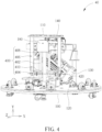
- FIG. 4 is a schematic diagram illustrating a motion simulator 40 according to an embodiment of the present invention.
- the motion simulator 40 includes a base plate 100, a carrying platform 110, a motion platform 120, a first actuator 130, a base 180, a second actuator 140 and a connecting assembly 400.
- the motion simulator 40 may be applied to the motion simulator 10 in FIG. 1 .
- the mechanism of the embodiments of the base plate 100, the carrying platform 110, the motion platform 120, the first actuator 130, the base 180 and the second actuator 140 is similar to the mechanism in FIG. 1 , FIG. 2 and FIG. 3 .
- the connecting assembly 400 is arranged between the base 180 and the carrying platform 110.
- the connecting assembly 400 includes an upper platform 408, a lower platform 410, an extension member 402, a rotating assembly 404 and a connecting member 406.
- the upper platform 408 is fixedly connected below the base 180.
- the lower platform 410 is arranged relative to the upper platform 408.
- the extension member 402 is fixedly connected between the upper platform 408 and the lower platform 410, and the rotating assembly 404 is rotatably arranged under the lower platform 410 through a bearing structure.
- the projection of the rotating assembly 404 on the plane formed by the X-direction axis and the Z-direction axis is fixed relative to the motion platform.
- the rotating assembly 404 is also rotated together.
- the connecting member 406 is (fixedly) arranged between the carrying platform 110 and the rotating assembly 404, and performs a rotation based on the second rotation axis 420.
- the motion platform 120 performs a rotation based on a rotation axis perpendicular to the motion platform 120, and a center of the carrying platform 110 is aligned with the rotation axis of the motion platform 120.
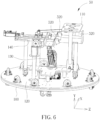
- FIG. 5 and FIG. 6 are schematic diagrams illustrating a motion simulator 50 according to an embodiment of the present invention.
- the motion simulator 50 includes a base plate 100, a carrying platform 110, a motion platform 120, a first actuator 130, a base 180, a second actuator 140 and a plurality of stoppers 500 (such as a failure stop structure), a plurality of first bumpers 510 and a plurality of second bumpers 520.
- the motion simulator 50 may be applied to the motion simulator 10 in FIG. 1 .
- the mechanism of the embodiments of the base plate 100, the carrying platform 110, the motion platform 120, the first actuator 130, the base 180 and the second actuator 140 is similar to the mechanism in FIG. 1 , FIG. 2 and FIG. 3 .
- similar descriptions for this embodiment are not repeated in detail here.
- the plurality of stoppers 500 are arranged on the motion platform 120 to control (or to limit) a movement range of the left-right movement of the carrying platform 110.
- the plurality of first bumpers 510 are arranged on both sides of the base 180.
- the plurality of first bumpers 510 buffer at least one impact between the base 180 and the plurality of stoppers 500.
- the base 180 and the carrying platform 110 are moved along the direction of the X-direction axis, the base 180 hits the left stopper in FIG. 5 .
- the left first bumper in FIG. 5 buffers an impact between the base 180 and the left stopper, such that the leftward movement range of the carrying platform 110 is controlled.
- the base 180 and the carrying platform 110 are moved in the opposite direction of the X-direction axis, the base 180 hits the right stopper in FIG. 5 .
- the right first bumper in FIG. 5 buffers an impact between the base 180 and the right stopper, such that the rightward movement range of the carrying platform 110 is controlled. Therefore, the plurality of stoppers 500 control the movement range of the carrying platform 110 to improve the safety of the motion simulator 50.
- the plurality of first bumpers 510 provide the function of buffering, such that a passenger who sits on the carrier may have a comfortable experience.
- the plurality of second bumpers 520 are arranged on the base extension surface 184.
- the second actuator 140 performs the forward-backward movement of the carrying platform 110
- at least one impact between the base extension surface 184 and the carrying platform 110 is buffered.
- the carrying platform 110 hits the second actuator 140.
- the right second bumper in FIG. 6 buffers an impact between the second actuator 140 and the carrying platform 110, such that the forward movement range of the carrying platform 110 is controlled.
- the carrying platform 110 when the carrying platform 110 is moved along the opposite direction of the Z-direction axis, the carrying platform 110 hits the second actuator 140.
- the plurality of second bumpers 520 provide a buffering function, such that a passenger sitting on the carrier may have a comfortable experience.
- FIG. 7 is a schematic diagram illustrating a link mechanism 700 of the motion simulator driving the carrying platform 110 to perform a left-right movement according to an embodiment of the present invention.
- the carrying platform 110 may be tilted left or right correspondingly.
- a first angle A is formed between a first link rod 710 and a second link rod 720.
- the carrying platform 110 does not be tilted left or right (as shown in the intermediate portion of FIG. 7 ).
- a second angle B that is smaller than the first angle A is formed between the first link rod 710 and the second link rod 720.
- the link mechanism 700 is retracted, and the carrying platform 110 may be driven by the link mechanism 700 to tilt right (as shown in the left portion of FIG. 7 ).
- a third angle C that is greater than the first angle A is formed between the first link 710 and the second link 720.
- the link mechanism 700 is extended, and the carrying platform 110 may be driven by the link mechanism 700 to tilt left (as shown in the left portion of FIG. 7 ). Therefore, the link mechanism 700 provides a left-right movement to drive the carrying platform 110, instead of the left-right movement of the carrying platform 110 through the other first actuator (such as an electric cylinder) in the prior art.
- the link mechanism 700 may reduce the computational complexity among the plurality of first actuators (such as electric cylinders).
- FIG. 8 is a schematic diagram illustrating a motion simulator 80 according to an embodiment of the present invention.
- the motion simulator 80 includes a carrying platform 110, a first actuator 130, a motor 310 and a belt drive assembly 800.
- the belt drive assembly 800 is movably connected to the motor 310 and the carrying platform 110 (e.g., a rotation axis 810 of the carrying platform 110), to convert the circular motion of the motor 310 into the linear motion, to perform the forward-backward movement of the carrying platform 110.
- the motor 310 and the belt drive assembly 800 provide the forward-backward movement to drive the carrying platform 110, which may replace the screw rod 326 and the sliding block 328 of the motion simulator 10 in FIG. 3 to provide a pitch motion for a passenger on the carrier.
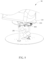
- FIG. 9 is a schematic diagram illustrating a motion simulator 90 according to an embodiment of the present invention.
- the X-direction axis, the Y-direction axis and the Z-direction axis are perpendicular to each other, and the X-direction axis is a direction entering the diagram, such that the X-direction is omitted here for simplicity.
- the motion simulator 90 includes a base plate 100, a carrying platform 110, a motion platform 120, a first actuator 130, a second actuator 140, a motor 910, a set of gear and belt 912, a cross bar 914, a plurality of stoppers 920 and a plurality of bumpers 930.
- a line connecting a center (e.g., a structural center) of the carrying platform 110 and a center (e.g., a rotation center) of the motion platform 120 is perpendicular to the motion platform 120.
- the center of the carrying platform 110 is aligned with the center of the motion platform 120, such that the probability of the carrying platform 110 is overturned when performing a pitch motion is reduced.
- the motor 910 is arranged under the carrying platform 110. Compared with the motor 310 of the motion simulator 10, the projection of the motor 910 on the X-Z plane does not exceed a maximum circle of the motion platform 120.
- the set of gear and belt 912 is configured to drive the operation of the motor 910. In accordance with the load requirement of the carrying platform 110, the set of gear and belt 912 may amplify the torque under the same specification and condition of the motor 910.
- the cross bar 914 is arranged under the carrying platform 110.
- the plurality of stoppers 920 and the plurality of bumpers 930 of the motion simulator 90 are configured to control (e.g., to limit) a movement range of the forward-backward movement of the carrying platform 110.
- the plurality of stoppers 920 are arranged on the base body 182 and extend upward on both sides of the base extension surface 184 to control (e.g., to limit) a movement range of the forward-backward movement of the carrying platform 110.
- the plurality of bumpers 930 are arranged on the plurality of stoppers 920 for buffering the impact force.
- the plurality of bumpers 930 may be a set of buffer foams, but the present invention is not limited thereto.
- the cross bar 914 under the carrying platform 110 hits the plurality of stoppers 920, and the plurality of bumpers 930 buffer at least one impact between the cross bar 914 and the plurality of stoppers 920.
- the cross bar 914 under the carrying platform 110 hits the right bumper of the plurality of bumpers 930 on the right stopper of the plurality of stoppers 920 in FIG. 9 , and the right bumper of the plurality of bumpers 930 in FIG.
- the cross bar 9 buffers an impact between the cross bar 914 and the right stopper, such that the movement range of the forward movement of the carrying platform 110 is controlled and the impact force is buffered.
- the carrying platform 110 is moved in the opposite direction of the Z-direction axis (e.g., a backward tilting of the carrying platform 110)
- the cross bar 914 under the carrying platform 110 hits the left bumper of the plurality of bumpers 930 on the left stopper of the plurality of stoppers 920 in FIG. 9
- the left bumper of the plurality of bumpers 930 in FIG. 9 buffers an impact between the cross bar 914 and the left stopper, such that the movement range of the backward movement of the carrying platform 110 is controlled and the impact force is buffered.
- the plurality of stoppers 920 and the plurality of bumpers 930 control a movement range of the forward tilting and the backward tilting of the carrying platform 110, and may also be used as a safety mechanism when the first actuator 130 (such as an electric cylinder) is broke down, in order to prevent the carrying platform 110 from unlimited forward-backward movement causing danger, so as to improve the safety of the motion simulator 90.
- the plurality of stoppers 920 and the plurality of bumpers 930 provide a buffering function, such that a passenger who sits on the carrier may have a comfortable experience.
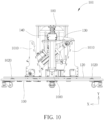
- FIG. 10 is a schematic diagram illustrating a motion simulator 101 according to an embodiment of the present invention.
- the X-direction axis, the Y-direction axis and the Z-direction axis are perpendicular to each other, and the Z-direction axis is a direction entering the diagram, such that the Z-direction is omitted here for simplicity.
- the motion simulator 101 includes a base plate 100, a carrying platform 110, a motion platform 120, a first actuator 130, a second actuator 140, a reducer motor 1000, a plurality of stoppers 1010 and a plurality of wheels 1020.
- the reducer motor 1000 is arranged on the base plate 100 and configured to drive the motion platform 120 to rotate relative to the base plate 100.
- the plurality of stoppers 1010 are used to control (e.g., to limit) a movement range of the left-right movement of the carrying platform 110.
- the method of controlling the left-right movement of the carrying platform 110 is similar to the plurality of stoppers 500 of the above-mentioned motion simulator 50.
- the shape of the plurality of stoppers 1010 of the motion simulator 101 is different from the shape of the plurality of stoppers 500 of the motion simulator 50.
- the shape of the plurality of stoppers 1010 is designed as a triangle, which may reduce the possibility of deformation during the impact of the carrying platform 110.
- the plurality of wheels 1020 are arranged between the base plate 100 and the motion platform 120.
- the plurality of wheels 1020 may be rollers. Compared with the plurality of wheels 170 in the motion simulator 10, the rollers may achieve a same supporting force with a smaller volume. Therefore, the distance between the motion platform 120 and the base plate 100 may be reduced, and the overall stability of the motion simulator 50 may be improved.
- the motion simulator 101 uses the reducer motor 1000 to drive the motion platform 120 to rotate, the plurality of wheels 1020 just need assisting the motion platform 120 in supporting without driving the motion platform 120 to rotate.
- the motion platform 120 is detachably arranged on the base plate 100. Both of the base plate 100 and the motion platform 120 have a combination interface, respectively. The two combination interfaces are aligned with each other, and the combination interfaces may be configured to be detachably connected to the first actuator 130 and the support assembly 150. In other words, since the base plate 100 and the motion platform 120 have the two combination interfaces, respectively and aligned with each other, the motion platform 120 and the plurality of wheels 170 may be removed from the motion simulator, and the base plate 100 may still be connected to the first actuator 130 and the support assembly 150, in order to provide various usages according to requirements.
- FIG. 11 is a schematic diagram illustrating a motion simulator 111 according to an embodiment of the present invention.
- the X-direction axis, the Y-direction axis and the Z-direction axis are perpendicular to each other, and the X-direction axis is a direction entering the diagram, such that the X-direction is omitted here for simplicity.
- the motion simulator 111 includes a base plate 100, a carrying platform 110, a first actuator 130, a second actuator 140 and a support assembly 150.
- the first actuator 130 and the supporting assembly 150 may still be directly arranged on the base plate 100 of the motion simulator 111.
- FIG. 12 is a schematic diagram illustrating a base plate 100 and a motion platform 120 of a motion simulator according to an embodiment of the present invention.
- An outer diameter of the base plate 100 e.g., 1000 mm
- the base plate 100 has a plurality of wheel interfaces 1200 for arranging the plurality of wheels, and the motion platform 120 has no wheel interface.
- the base plate 100 has a plurality of caster interfaces 1202 for arranging the plurality of casters, and the motion platform 120 has no caster interface.
- the base plate has a reducer combination interface 1204 for arranging the reducer motor, and the motion platform 120 has no reducer combination interface 1204.
- the base plate 100 and the motion platform 120 have a first actuator interface 1206 and a support assembly interface 1208, respectively.
- the first actuator interface 1206 and the support assembly interface 1208 are aligned with each other.
- the first actuator interface 1206 is configured to arrange the first actuator 130, and the support assembly interface 1208 is configured to arrange the support assembly 150.
- the present invention provides a motion simulator.
- One actuator of the motion simulator performs a movement, for example, the first actuator performs the left-right movement of the carrying platform (such as a roll motion), and the second actuator performs the forward-backward movement of the carrying platform (such as a pitch motion).
- the present invention may simulate various motions. Compared with a general Stewart platform, the present invention has a simple structure and a lower setting cost, and the operation of the motion simulator is easier.
- the plurality of stoppers and the plurality of bumpers improve the safety of the motion simulator, and the passenger may have a comfortable experience.
Landscapes
- Engineering & Computer Science (AREA)
- Theoretical Computer Science (AREA)
- Educational Administration (AREA)
- Educational Technology (AREA)
- Aviation & Aerospace Engineering (AREA)
- General Physics & Mathematics (AREA)
- Business, Economics & Management (AREA)
- Physics & Mathematics (AREA)
- Health & Medical Sciences (AREA)
- General Health & Medical Sciences (AREA)
- Dentistry (AREA)
- Management, Administration, Business Operations System, And Electronic Commerce (AREA)
- Manipulator (AREA)
- Magnetic Resonance Imaging Apparatus (AREA)
- Apparatus For Radiation Diagnosis (AREA)
- Valve Device For Special Equipments (AREA)
Claims (13)
- Bewegungssimulator (10, 40, 50, 80, 90, 101, 111), aufweisend:eine Grundplatte (100);eine bewegliche Plattform (120), die auf der Grundplatte (100) angeordnet und beweglich mit der Grundplatte (100) verbunden ist;einen ersten Aktuator (130), der auf der beweglichen Plattform (120) angeordnet und beweglich mit der beweglichen Plattform (120) verbunden ist;ein Basiselement (180) mit einem Grundkörper (182), der sich in einer Längsrichtung erstreckt, und einer Basiserweiterungsfläche(184), die sich in einer Breitenrichtung erstreckt, wobei der erste Aktuator (130) beweglich mit der Basiserweiterungsfläche (184) verbunden ist;einen zweiten Aktuator (140), der beweglich auf dem Basiselement (180) angeordnet ist; undeine Tragplattform (110), die beweglich mit dem zweiten Aktuator (140) verbunden ist, wobei durch eine Verbindungsbeziehung zwischen dem Basiselement (180) und dem zweiten Aktuator (140), der auf dem Basiselement (180) angeordnet ist, der erste Aktuator (130) eine Links-Rechts-Bewegung der Tragplattform (110) relativ zu der beweglichen Plattform (120) ausführt und der zweite Aktuator (140) eine Vorwärts-Rückwärts-Bewegung der Tragplattform (110) relativ zu der beweglichen Plattform (120) ausführt,dadurch gekennzeichnet, dass der zweite Aktuator (140) Folgendes aufweist:einen Motor (310), der konfiguriert ist, um eine kreisförmige Bewegung auszuführen; undeine Umwandlungsbaugruppe (320), die auf dem Basiselement (180) angeordnet ist und beweglich zwischen dem Motor (310) und der Tragplattform (110) verbunden ist, wobei die Umwandlungsbaugruppe (320) Folgendes aufweist:ein Linearbewegungselement (322), das beweglich mit dem Motor (310) verbunden ist und das die kreisförmige Bewegung des Motors (310) in eine lineare Bewegung entlang der Längsrichtung des Basiselements (180) umwandelt, um die Vorwärts-Rückwärts-Bewegung der Tragplattform (110) auszuführen.
- Bewegungssimulator (10, 40, 50, 80, 90, 101, 111) nach Anspruch 1, weiterhin aufweisend:
eine Stützanordnung (150), die auf der beweglichen Plattform (120) angeordnet ist und die zwischen der beweglichen Plattform (120) und dem Grundkörper (182) verbunden ist, wobei die Stützanordnung (150) Folgendes aufweist:eine erste Stützstange (152), die auf der beweglichen Plattform (120) angeordnet ist, wobei die erste Stützstange (152) ein Ende aufweist, das schwenkbar mit der beweglichen Plattform (120) verbunden ist und ein anderes Ende aufweist, das fest auf dem Grundkörper (182) angeordnet ist; undeine zweite Stützstange (154), die auf der beweglichen Plattform (120) angeordnet ist, die ein Ende aufweist, das schwenkbar mit der beweglichen Plattform (120) verbunden ist und die ein anderes Ende aufweist, das fest auf dem Grundkörper (182) angeordnet ist, wobei die erste Stützstange (152) und die zweite Stützstange (154) auf entgegengesetzt gelegenen Seiten der Basiserweiterungsfläche (184) angeordnet sind. - Bewegungssimulator (10, 40, 50, 80, 90, 101, 111) nach Anspruch 2, wobei der erste Aktuator (130) weiterhin Folgendes aufweist:einen Basisabschnitt (200), der auf der beweglichen Plattform (120) angeordnet ist, wobei ein unteres Ende des Basisabschnitts (200) beweglich mit der beweglichen Plattform (120) verbunden ist; undeinen Erweiterungsabschnitt (220), wobei ein unteres Ende des Erweiterungsabschnitts (220) mit einem oberen Ende des Basisabschnitts (200) verbunden ist und ein oberes Ende des Erweiterungsabschnitts (220) beweglich mit der Basiserweiterungsfläche (184) verbunden ist, wobei gemäß einem Steuerereignis des Basisabschnitts (200) der Erweiterungsabschnitt (220) erweitert oder zurückgezogen wird, um die Links-Rechts-Bewegung auszuführen.
- Bewegungssimulator (10, 40, 50, 80, 90, 101, 111) nach Anspruch 3, wobei eine Schwenkverbindung zwischen der ersten Stützstange (152) und der beweglichen Plattform (120) und eine Schwenkverbindung zwischen der zweiten Stützstange (154) und der beweglichen Plattform (120) von einer ersten Drehachse (240) durchdrungen werden, und wenn der Erweiterungsabschnitt (220) des ersten Aktuators (130) erweitert oder zurückgezogen wird, das Basiselement (180) und die Tragplattform (110) die Links-Rechts-Bewegung auf Grundlage der ersten Drehachse (240) ausführen.
- Bewegungssimulator (10, 40, 50, 80, 90, 101, 111) nach einem der vorhergehenden Ansprüche, wobei die Umwandlungsbaugruppe (320) weiterhin Folgendes aufweist: eine Zugstange (324), die beweglich mit dem Linearbewegungselement (322) und der Tragplattform (110) verbunden ist und die konfiguriert ist, um die Vorwärts-Rückwärts-Bewegung der Tragplattform (110) gemäß der linearen Bewegung auszuführen.
- Bewegungssimulator (10, 40, 50, 80, 90, 101, 111) nach einem der vorhergehenden Ansprüche, wobei das Linearbewegungselement (322) Folgendes aufweist:eine Schraubenstange (326), die auf dem Basiselement (180) angeordnet und die mit dem Motor (310) verbunden ist; undeinen Gleitblock (328), der auf der Schraubenstange (326) angeordnet und konfiguriert ist, um die lineare Bewegung auf der Schraubenstange (326) gemäß der kreisförmigen Bewegung des Motors (310) auszuführen.
- Bewegungssimulator (10, 40, 50, 80, 90, 101, 111) nach Anspruch 6, wobei gemäß einem ersten Gelenk (30) der Gleitblock (328) beweglich mit einem Ende der Zugstange (324) verbunden ist und gemäß einem zweiten Gelenk (32) ein anderes Ende der Zugstange (324) beweglich mit der Tragplattform (110) verbunden ist, so dass, wenn der Gleitblock (328) die lineare Bewegung auf der Schraubenstange (326) ausführt, die Tragplattform (110) die Vorwärts-Rückwärts-Bewegung basierend auf einer zweiten Drehachse (420) ausführt.
- Bewegungssimulator (40) nach Anspruch 7, weiterhin aufweisend:
eine Verbindungsbaugruppe (400), die zwischen dem Basiselement (180) und der Tragplattform (110) angeordnet ist, wobei die Verbindungsbaugruppe (400) Folgendes aufweist:eine obere Plattform (408), die fest unter dem Basiselement (180) verbunden ist;eine untere Plattform (410), die relativ zu der oberen Plattform (408) angeordnet ist;ein Erweiterungselement, das fest zwischen der oberen Plattform (408) und der unteren Plattform (410) verbunden ist;eine Drehbaugruppe (404), die drehbar unter der unteren Plattform (410) durch eine Lagerstruktur angeordnet ist, um die zweite Drehachse (420) zu bilden; undein Verbindungselement (406), das zwischen der Tragplattform (110) und der Drehbaugruppe (404) angeordnet ist und das konfiguriert ist, um eine Drehung basierend auf der zweiten Drehachse (420) auszuführen. - Bewegungssimulator (10, 40, 50, 80, 90, 101, 111) nach einem der Ansprüche 1 bis 8, wobei die bewegliche Plattform (120) eine Drehung basierend auf einer Drehachse senkrecht zu der beweglichen Plattform (120) ausführt und eine Mitte der Tragplattform (110) mit der Drehachse der beweglichen Plattform (120) ausgerichtet ist.
- Bewegungssimulator (50, 90, 101) nach einem der Ansprüche 1 bis 9, weiterhin aufweisend:eine Vielzahl von Anschlagelementen (500, 920, 1010), die auf der beweglichen Plattform (120) angeordnet sind und die konfiguriert sind, um einen Bewegungsbereich der Links-Rechts-Bewegung zu steuern; undeine Vielzahl von ersten Pufferelementen (510), die auf beiden Seiten des Basiselements (180) angeordnet sind und die konfiguriert sind, um mindestens einen Stoß zwischen dem Basiselement (180) und der Vielzahl von Anschlagelementen (500, 920, 1010) zu puffern, wenn der erste Aktuator (130) die Links-Rechts-Bewegung ausführt.
- Bewegungssimulator (50) nach Anspruch 10, weiterhin aufweisend:
eine Mehrzahl von zweiten Pufferelementen (520), die auf der Basiserweiterungsfläche (184) angeordnet sind und die konfiguriert sind, um mindestens einen Stoß zwischen der Basiserweiterungsfläche (184) und der Tragplattform (110) zu puffern, wenn der zweite Aktuator (140) die Vorwärts-Rückwärts-Bewegung ausführt. - Bewegungssimulator (10, 40, 50, 80, 90, 101, 111) nach einem der Ansprüche 1 bis 11, wobei die Grundplatte (100) eine Kombinationsschnittstelle (1204) aufweist, die bewegliche Plattform (120) eine Kombinationsschnittstelle (1204) aufweist, die zwei Kombinationsschnittstellen (1204) miteinander ausgerichtet sind und die bewegliche Plattform (120) durch die Kombinationsschnittstelle (1204) lösbar mit dem ersten Aktuator (130) und der Stützanordnung (150) verbunden ist.
- Bewegungssimulator (10, 40, 50, 80, 90, 101, 111) nach Anspruch 12, wobei die bewegliche Plattform (120) lösbar auf der Grundplatte (100) angeordnet ist, und wenn die bewegliche Plattform (120) gelöst ist, die Grundplatte (100) durch die Kombinationsschnittstelle (1204) lösbar mit dem ersten Aktuator (130) und der Stützanordnung (150) verbunden ist.
Applications Claiming Priority (1)
| Application Number | Priority Date | Filing Date | Title |
|---|---|---|---|
| TW110133124A TWI792539B (zh) | 2021-09-07 | 2021-09-07 | 體感模擬器 |
Publications (3)
| Publication Number | Publication Date |
|---|---|
| EP4145424A1 EP4145424A1 (de) | 2023-03-08 |
| EP4145424B1 true EP4145424B1 (de) | 2024-11-06 |
| EP4145424C0 EP4145424C0 (de) | 2024-11-06 |
Family
ID=82595187
Family Applications (1)
| Application Number | Title | Priority Date | Filing Date |
|---|---|---|---|
| EP22184580.3A Active EP4145424B1 (de) | 2021-09-07 | 2022-07-13 | Bewegungssimulator |
Country Status (4)
| Country | Link |
|---|---|
| US (1) | US12214290B2 (de) |
| EP (1) | EP4145424B1 (de) |
| JP (1) | JP7307430B2 (de) |
| TW (1) | TWI792539B (de) |
Family Cites Families (12)
| Publication number | Priority date | Publication date | Assignee | Title |
|---|---|---|---|---|
| JPH0595571A (ja) | 1991-10-01 | 1993-04-16 | Hitachi Ltd | Crt画面測定用カメラ保持装置 |
| US20030219701A1 (en) * | 2000-05-12 | 2003-11-27 | Zeier Bruce E. | Simulator for aircraft flight training |
| EP2623169A1 (de) | 2012-02-06 | 2013-08-07 | Brogent Technologies, inc. | Biaxialer dynamischer Aufhängungssimulator |
| KR101377594B1 (ko) * | 2013-02-20 | 2014-03-25 | 주식회사 모션디바이스 | 모션 시뮬레이터 |
| CN104835399B (zh) * | 2015-03-17 | 2017-08-15 | 山西省交通科学研究院 | 一种模拟交通工具高低频运动的仿真平台及其实施方法 |
| CN105858535B (zh) * | 2016-05-16 | 2018-04-20 | 国网江苏省电力有限公司宿迁供电分公司 | 一种电力检修支撑装置 |
| AT523942B1 (de) * | 2021-02-05 | 2022-01-15 | V&P Rides Gmbh | Bewegungssimulationsvorrichtung für ein Unterhaltungssystem |
| WO2019031539A1 (ja) | 2017-08-09 | 2019-02-14 | 公立大学法人広島市立大学 | モーションベース |
| CN107424473A (zh) * | 2017-08-14 | 2017-12-01 | 徐舒青 | 单座全动飞机模拟驾驶设备 |
| TWI767505B (zh) * | 2021-01-08 | 2022-06-11 | 智崴資訊科技股份有限公司 | 體感模擬器 |
| CN113230663A (zh) * | 2021-04-06 | 2021-08-10 | 徐州拓普互动智能科技有限公司 | 一种高安全性六轴vr赛车运动平台 |
| TWI782596B (zh) * | 2021-06-26 | 2022-11-01 | 智崴資訊科技股份有限公司 | 移動模擬裝置 |
-
2021
- 2021-09-07 TW TW110133124A patent/TWI792539B/zh active
-
2022
- 2022-06-07 US US17/834,921 patent/US12214290B2/en active Active
- 2022-06-28 JP JP2022103348A patent/JP7307430B2/ja active Active
- 2022-07-13 EP EP22184580.3A patent/EP4145424B1/de active Active
Also Published As
| Publication number | Publication date |
|---|---|
| TW202312112A (zh) | 2023-03-16 |
| JP2023038898A (ja) | 2023-03-17 |
| US20230075870A1 (en) | 2023-03-09 |
| JP7307430B2 (ja) | 2023-07-12 |
| TWI792539B (zh) | 2023-02-11 |
| US12214290B2 (en) | 2025-02-04 |
| EP4145424A1 (de) | 2023-03-08 |
| EP4145424C0 (de) | 2024-11-06 |
Similar Documents
| Publication | Publication Date | Title |
|---|---|---|
| EP3917631B1 (de) | Bewegungssimulationsgerät | |
| JP5389268B2 (ja) | 可動プラットフォーム | |
| US7033177B2 (en) | Motion simulator | |
| EP3278323B1 (de) | Bewegungsanordnung | |
| EP3563915A1 (de) | Bewegungssimulationsvorrichtung | |
| EP4145424B1 (de) | Bewegungssimulator | |
| EP4108305B1 (de) | Bewegungssimulationsgerät | |
| WO2019069077A1 (en) | MOVEMENT DEVICE | |
| KR102580729B1 (ko) | 모션 시뮬레이터 | |
| JPH05285273A (ja) | ゲーム機の昇降機構 | |
| JP2023167574A (ja) | モーションプラットフォーム及びレーシングシミュレータ | |
| CN115770397A (zh) | 体感模拟器 | |
| CN220142597U (zh) | 一种赛车驾驶模拟装置 | |
| KR102775368B1 (ko) | 크랭크 방식의 모션 플랫폼 및 모션 플랫폼 제어방법 | |
| TWI720631B (zh) | 一種電動輪椅 | |
| CN107878140B (zh) | 一种车辆 | |
| WO2024094960A1 (en) | Motion generation apparatus | |
| CN119283733A (zh) | 一种零重力座椅骨架机构以及车辆 | |
| KR20230023933A (ko) | 하중 중심 지주를 이용한 시소 방식의 3축 플라이트 시뮬레이터 |
Legal Events
| Date | Code | Title | Description |
|---|---|---|---|
| PUAI | Public reference made under article 153(3) epc to a published international application that has entered the european phase |
Free format text: ORIGINAL CODE: 0009012 |
|
| STAA | Information on the status of an ep patent application or granted ep patent |
Free format text: STATUS: THE APPLICATION HAS BEEN PUBLISHED |
|
| AK | Designated contracting states |
Kind code of ref document: A1 Designated state(s): AL AT BE BG CH CY CZ DE DK EE ES FI FR GB GR HR HU IE IS IT LI LT LU LV MC MK MT NL NO PL PT RO RS SE SI SK SM TR |
|
| STAA | Information on the status of an ep patent application or granted ep patent |
Free format text: STATUS: REQUEST FOR EXAMINATION WAS MADE |
|
| 17P | Request for examination filed |
Effective date: 20230802 |
|
| RBV | Designated contracting states (corrected) |
Designated state(s): AL AT BE BG CH CY CZ DE DK EE ES FI FR GB GR HR HU IE IS IT LI LT LU LV MC MK MT NL NO PL PT RO RS SE SI SK SM TR |
|
| GRAP | Despatch of communication of intention to grant a patent |
Free format text: ORIGINAL CODE: EPIDOSNIGR1 |
|
| STAA | Information on the status of an ep patent application or granted ep patent |
Free format text: STATUS: GRANT OF PATENT IS INTENDED |
|
| INTG | Intention to grant announced |
Effective date: 20240611 |
|
| GRAS | Grant fee paid |
Free format text: ORIGINAL CODE: EPIDOSNIGR3 |
|
| GRAA | (expected) grant |
Free format text: ORIGINAL CODE: 0009210 |
|
| STAA | Information on the status of an ep patent application or granted ep patent |
Free format text: STATUS: THE PATENT HAS BEEN GRANTED |
|
| AK | Designated contracting states |
Kind code of ref document: B1 Designated state(s): AL AT BE BG CH CY CZ DE DK EE ES FI FR GB GR HR HU IE IS IT LI LT LU LV MC MK MT NL NO PL PT RO RS SE SI SK SM TR |
|
| REG | Reference to a national code |
Ref country code: GB Ref legal event code: FG4D |
|
| REG | Reference to a national code |
Ref country code: CH Ref legal event code: EP |
|
| REG | Reference to a national code |
Ref country code: DE Ref legal event code: R096 Ref document number: 602022007400 Country of ref document: DE |
|
| REG | Reference to a national code |
Ref country code: IE Ref legal event code: FG4D |
|
| U01 | Request for unitary effect filed |
Effective date: 20241106 |
|
| U07 | Unitary effect registered |
Designated state(s): AT BE BG DE DK EE FI FR IT LT LU LV MT NL PT RO SE SI Effective date: 20241112 |
|
| U1N | Appointed representative for the unitary patent procedure changed after the registration of the unitary effect |
Representative=s name: LUCKE, ANDREAS; DE |
|
| PG25 | Lapsed in a contracting state [announced via postgrant information from national office to epo] |
Ref country code: IS Free format text: LAPSE BECAUSE OF FAILURE TO SUBMIT A TRANSLATION OF THE DESCRIPTION OR TO PAY THE FEE WITHIN THE PRESCRIBED TIME-LIMIT Effective date: 20250306 Ref country code: HR Free format text: LAPSE BECAUSE OF FAILURE TO SUBMIT A TRANSLATION OF THE DESCRIPTION OR TO PAY THE FEE WITHIN THE PRESCRIBED TIME-LIMIT Effective date: 20241106 |
|
| PG25 | Lapsed in a contracting state [announced via postgrant information from national office to epo] |
Ref country code: ES Free format text: LAPSE BECAUSE OF FAILURE TO SUBMIT A TRANSLATION OF THE DESCRIPTION OR TO PAY THE FEE WITHIN THE PRESCRIBED TIME-LIMIT Effective date: 20241106 |
|
| PG25 | Lapsed in a contracting state [announced via postgrant information from national office to epo] |
Ref country code: NO Free format text: LAPSE BECAUSE OF FAILURE TO SUBMIT A TRANSLATION OF THE DESCRIPTION OR TO PAY THE FEE WITHIN THE PRESCRIBED TIME-LIMIT Effective date: 20250206 |
|
| PG25 | Lapsed in a contracting state [announced via postgrant information from national office to epo] |
Ref country code: GR Free format text: LAPSE BECAUSE OF FAILURE TO SUBMIT A TRANSLATION OF THE DESCRIPTION OR TO PAY THE FEE WITHIN THE PRESCRIBED TIME-LIMIT Effective date: 20250207 |
|
| PG25 | Lapsed in a contracting state [announced via postgrant information from national office to epo] |
Ref country code: PL Free format text: LAPSE BECAUSE OF FAILURE TO SUBMIT A TRANSLATION OF THE DESCRIPTION OR TO PAY THE FEE WITHIN THE PRESCRIBED TIME-LIMIT Effective date: 20241106 |
|
| PG25 | Lapsed in a contracting state [announced via postgrant information from national office to epo] |
Ref country code: RS Free format text: LAPSE BECAUSE OF FAILURE TO SUBMIT A TRANSLATION OF THE DESCRIPTION OR TO PAY THE FEE WITHIN THE PRESCRIBED TIME-LIMIT Effective date: 20250206 |
|
| PG25 | Lapsed in a contracting state [announced via postgrant information from national office to epo] |
Ref country code: SM Free format text: LAPSE BECAUSE OF FAILURE TO SUBMIT A TRANSLATION OF THE DESCRIPTION OR TO PAY THE FEE WITHIN THE PRESCRIBED TIME-LIMIT Effective date: 20241106 |
|
| PG25 | Lapsed in a contracting state [announced via postgrant information from national office to epo] |
Ref country code: SK Free format text: LAPSE BECAUSE OF FAILURE TO SUBMIT A TRANSLATION OF THE DESCRIPTION OR TO PAY THE FEE WITHIN THE PRESCRIBED TIME-LIMIT Effective date: 20241106 |
|
| PG25 | Lapsed in a contracting state [announced via postgrant information from national office to epo] |
Ref country code: CZ Free format text: LAPSE BECAUSE OF FAILURE TO SUBMIT A TRANSLATION OF THE DESCRIPTION OR TO PAY THE FEE WITHIN THE PRESCRIBED TIME-LIMIT Effective date: 20241106 |
|
| U20 | Renewal fee for the european patent with unitary effect paid |
Year of fee payment: 4 Effective date: 20250701 |
|
| PLBE | No opposition filed within time limit |
Free format text: ORIGINAL CODE: 0009261 |
|
| STAA | Information on the status of an ep patent application or granted ep patent |
Free format text: STATUS: NO OPPOSITION FILED WITHIN TIME LIMIT |
|
| 26N | No opposition filed |
Effective date: 20250807 |