EP4139101B1 - Unterdruck-transportband für eine automatische messer-zuschneidvorrichtung für blattförmiges gut - Google Patents
Unterdruck-transportband für eine automatische messer-zuschneidvorrichtung für blattförmiges gut Download PDFInfo
- Publication number
- EP4139101B1 EP4139101B1 EP21740158.7A EP21740158A EP4139101B1 EP 4139101 B1 EP4139101 B1 EP 4139101B1 EP 21740158 A EP21740158 A EP 21740158A EP 4139101 B1 EP4139101 B1 EP 4139101B1
- Authority
- EP
- European Patent Office
- Prior art keywords
- cutting
- sole
- conveyor according
- slots
- conveyor
- Prior art date
- Legal status (The legal status is an assumption and is not a legal conclusion. Google has not performed a legal analysis and makes no representation as to the accuracy of the status listed.)
- Active
Links
Images


Classifications
-
- B—PERFORMING OPERATIONS; TRANSPORTING
- B26—HAND CUTTING TOOLS; CUTTING; SEVERING
- B26D—CUTTING; DETAILS COMMON TO MACHINES FOR PERFORATING, PUNCHING, CUTTING-OUT, STAMPING-OUT OR SEVERING
- B26D7/00—Details of apparatus for cutting, cutting-out, stamping-out, punching, perforating, or severing by means other than cutting
- B26D7/01—Means for holding or positioning work
- B26D7/018—Holding the work by suction
-
- B—PERFORMING OPERATIONS; TRANSPORTING
- B26—HAND CUTTING TOOLS; CUTTING; SEVERING
- B26D—CUTTING; DETAILS COMMON TO MACHINES FOR PERFORATING, PUNCHING, CUTTING-OUT, STAMPING-OUT OR SEVERING
- B26D7/00—Details of apparatus for cutting, cutting-out, stamping-out, punching, perforating, or severing by means other than cutting
- B26D7/06—Arrangements for feeding or delivering work of other than sheet, web, or filamentary form
- B26D7/0625—Arrangements for feeding or delivering work of other than sheet, web, or filamentary form by endless conveyors, e.g. belts
-
- B—PERFORMING OPERATIONS; TRANSPORTING
- B26—HAND CUTTING TOOLS; CUTTING; SEVERING
- B26D—CUTTING; DETAILS COMMON TO MACHINES FOR PERFORATING, PUNCHING, CUTTING-OUT, STAMPING-OUT OR SEVERING
- B26D7/00—Details of apparatus for cutting, cutting-out, stamping-out, punching, perforating, or severing by means other than cutting
- B26D7/08—Means for treating work or cutting member to facilitate cutting
- B26D7/088—Means for treating work or cutting member to facilitate cutting by cleaning or lubricating
-
- B—PERFORMING OPERATIONS; TRANSPORTING
- B26—HAND CUTTING TOOLS; CUTTING; SEVERING
- B26D—CUTTING; DETAILS COMMON TO MACHINES FOR PERFORATING, PUNCHING, CUTTING-OUT, STAMPING-OUT OR SEVERING
- B26D7/00—Details of apparatus for cutting, cutting-out, stamping-out, punching, perforating, or severing by means other than cutting
- B26D7/20—Cutting beds
Definitions
- the present invention relates to a suction cutting conveyor for an automatic cutting machine for sheet materials, in particular textile materials, using a vibrating blade penetrating into the cutting support.
- a conveyor according to the preamble of claim 1 is described in EP 2 656 987 A1 .
- a vibrating blade cutting machine includes a cutting conveyor which serves to drive the stack of sheets during the cutting operation.
- This cutting conveyor is housed in a box inside which a strong depression is established in order to keep the sheets of material to be cut stationary during the cutting operation.
- the cutting conveyor also serves as a penetrating cutting support for the vibrating blade. It is in fact well known to make the cutting support penetrable by the blade so that during the cutting operation, the blade can not only completely pass through the material to be cut, but also extend downward beyond the support surface and in the bed of material providing such a surface.
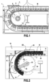
- the conveyor 1 generally comprises a plurality of cutting supports 2 which are each secured to a belt 3 of a drive conveyor.
- This conveyor also includes at each end of the table a pinion 5 centered on a horizontal axis 4 and driving the belt 3 along rectilinear and curvilinear trajectories.
- each cutting support 2 comprises a plurality of bristles 6 mounted on a sole 7 forming several parallel rows of bristles, each bristle having a head forming the support for the sheet material to be cut. Passages made through the sole allow the suction air to pass.
- the pivoting of the cutting supports forces the material discharge combs 8 at the end of the cutting surface to be positioned at a height h above the cutting surface.
- this difference in height is detrimental for the user of the cutting machine because, when the cutting mat M passes, the material can deform by stretching and thus impact the pieces cut at this location or when loading the mat ( side opposite the unloading), the material is stretched then compressed during the depression phase, thus creating stresses in this material which can degrade the quality of the cut parts.
- the material unloading combs 8 must be positioned offset from the vertical of the horizontal axes 4 driving the pinions 5 of the conveyor in order to avoid the opening zone between the cutting supports creating a gap in head of hair where the material can rush in if the combs do not prevent them.
- This constraint requires having long combs subject to depression and requiring them to be dimensioned according to these constraints.
- the useful cutting length may be reduced to avoid this zone.
- the invention therefore aims to provide a cutting support which does not have the aforementioned drawbacks.
- the invention is remarkable in that the cutting supports each have a sole which has a degree of bending in the transverse direction, which allows them to deform to follow the trajectories of the drive mechanism, in particular during rotation of the conveyor at the upstream and downstream ends of the table to turn around.
- the invention is also remarkable in that the plane of the cutting support drive mechanism is located in the plane of the cutting support sole.
- the gap between adjacent cutting supports is reduced, which makes it possible to further extend the cutting surface to the same conveyor dimension.
- the cutting supports - and more particularly their respective soles - deform but do not pivot, which allows the combs or rakes to be lowered at the upstream and downstream end of the cutting surface. In this way, it is possible to prevent the material from being deformed by stretching with all the problems that this generates.
- each cutting support may have a plurality of parallel geometric shapes which extend in directions perpendicular to the direction of advance of the drive mechanism to allow it to deform elastically following the trajectories of the drive mechanism. These shapes allow the sole to be flexible while keeping the bristles perpendicular to the tangency of this sole even during the period of operation.
- the geometric shapes of the sole of the cutting supports can be constituted by a plurality of parallel slots.
- the slots of the sole may include external slots projecting outwardly relative to an external surface of the sole and/or internal slots projecting inwardly relative to an internal surface of the sole.
- the slots of the sole may comprise an alternation of external slots and internal slots so as to give an accordion shape.
- the niches can have a rectangular, square or rounded section.
- each cutting support can be made of plastic material, this material having to be compatible with the deformations induced during operation.
- the cutting supports can each be mounted by their respective sole on a transmission member of the drive mechanism via at least one fixing slat.
- each cutting support can be mounted on the transmission member of the drive mechanism via at least two fixing slats spaced longitudinally from each other. At least one of the two fixing slats can cooperate with two adjacent cutting supports.
- the invention also relates to an automatic blade cutting machine for sheet materials comprising a conveyor as defined above.
- the present invention relates to cutting supports for a suction cutting conveyor of an automatic blade cutting machine for sheet materials, such as the conveyor 10 partially shown in the figure 2 .
- such a cutting conveyor 10 serves to drive the stack of sheets during the cutting operation.
- This cutting conveyor 10 is typically housed in a box 12 inside which a strong depression is established in order to keep the sheets of material to be cut stationary during the cutting operation.
- the cutting conveyor also serves as a penetrating cutting support for the vibrating blade. It is in fact well known to make the cutting support penetrable by the blade so that during the cutting operation, the blade can not only completely pass through the material to be cut, but also extend downward beyond the support surface and in the bed of material providing such a surface.
- the cutting conveyor 10 generally comprises a plurality of cutting supports 14.
- Each cutting support comprises a plurality of bristles 16 each having a foot 16a mounted on a sole 18 forming several rows parallel bristles, and a head 16b opposite the foot and on which is intended to rest the material in sheets to be cut (see the Figure 3 ).
- the cutting supports 14 are mounted via their respective soles on a drive belt 20 driven at each end of the table by pinions 24 centered on horizontal axes 22.
- the drive belt 20 is thus driven according to rectilinear (between the two ends of the cutting table) and curvilinear (at each end of the cutting table to turn around) trajectories.
- the drive belt could be replaced by a chain, a toothed belt or any other drive mechanism.
- transverse channels 25 are made through the soles of the cutting supports in order to allow the suction air to pass through the soles ( Figure 4 ).
- the cutting supports thus make it possible to support the material to be cut under suction while being able to be penetrated by the cutting blade. They delimit the cutting surface S of the cutting machine.
- the cutting table comprises a plurality of unloading combs 26 which are generally raised relative to the cutting surface (see the prior art of the figure 1 ). These unloading combs 26 extend over the entire width of the cutting surface and thus help to unload the material out of the cutting surface.
- the cutting table also includes a plurality of loading combs (not shown in the figures) which are generally raised relative to the cutting surface and which help to load the material onto the cutting surface.
- the sole 18 on which the bristles 16 of the different cutting supports are mounted is capable of being able to deform elastically following the trajectories of the drive belt 20.
- the sole 18 of each cutting support has a plurality of parallel geometric shapes which extend in directions perpendicular to the direction of advance of the drive belt to allow it to deform elastically following the trajectories of the belt 'training.
- the geometric shapes of the sole of the cutting supports are here constituted by a plurality of parallel slots (or folds) which extend in a transverse direction (that is to say which extend in a direction perpendicular to the direction of advance T of the cutting conveyor).
- the slots are composed of external slots 28a projecting towards the outside of the sole and internal slots 28b projecting towards the inside of the support.
- the slots 28a, 28b are arranged alternately so as to give an accordion shape to the sole giving it its properties of aptitude for plastic deformation.
- the slots have a rectangular section. This section could alternatively be square or rounded.
- the slots of the sole could only be present on one of the two faces of the sole (that is to say projecting towards the outside or towards the inside only of the sole).
- elastic deformation is made possible thanks to the particular shape of the sole. It thus makes it possible, on the one hand to avoid too large an opening between the adjacent cutting supports, and on the other hand to limit, or even reduce to zero, the height of elevation of the unloading combs 26 relative to the surface of S cut.
- the sole 18' of the cutting supports has intrinsic characteristics giving it an elastic deformation property due to its composition.
- the sole 18' is made of a plastic material capable of allowing it to deform elastically following the trajectories of the drive mechanism (on the Figure 6 , the 18' sole is in a deformed state).
- the plastic material will be chosen for example from the polyamide or polypropylene families.
- Figure 6 represents a modular cutting support element 36 as described in detail in the patent application FR 20/03043 filed on March 27, 2020 by the Applicant.
- This modular element 36 comprises a plurality of bristles 16' arranged along the same and single line and whose respective feet are integral with a sole 18' made of a plastic material capable of allowing it to deform elastically.
- the sole 18' is provided with a plurality of transverse channels 25' for the passage of suction air.
- the sole and the bristles of a cutting support are made of different materials (in particular plastics).
- each cutting support 14 is mounted on the drive belt 20 via two fixing slats 30 spaced longitudinally from one another.
- each cutting support can be mounted on the drive belt via three fixing slats spaced longitudinally from one another.
- each cutting support is mounted on the drive belt via three fixing slats; a fixing slat mounted only on the slat, and two other fixing slats mounted in common on the cutting support and on the two adjacent cutting supports.
- the cutting conveyor 10 may further comprise a device for cleaning the cutting supports 14 with air.
- This cleaning device comprises in particular an air blowing nozzle 32 which is mounted on the horizontal axis 22 of one of the pinions 24 and which extends along a radius thereof.
- the nozzle 32 comes to bear against the external face of the sole of the cutting supports and blows air through it to take off dust and impurities lodged at the bottom of the sole.
- a collector 34 positioned opposite the cutting support on the side of the hair head makes it possible to recover the dust thus dislodged.
Landscapes
- Life Sciences & Earth Sciences (AREA)
- Forests & Forestry (AREA)
- Engineering & Computer Science (AREA)
- Mechanical Engineering (AREA)
- Treatment Of Fiber Materials (AREA)
- Details Of Cutting Devices (AREA)
- Control Of Cutting Processes (AREA)
Claims (13)
- Ansaugschneidförderer (10) einer Maschine zum automatischen Schneiden von Bogenmaterialien mittels Klinge, der mehrere Schneidunterlagen (14, 14') umfasst, die fest mit einem Mitnahmemechanismus verbunden sind, der entlang geradliniger und gekrümmter Bahnen mitgenommen wird, wobei jede Schneidunterlage mehrere Borsten (16; 16') umfasst, die jeweils einen Fuß (16a), der fest mit einer Sohle (18; 18') verbunden ist, und einen Kopf (16b) aufweisen, der dem Fuß entgegengesetzt ist und zum Aufliegen eines zuzuschneidenden Bogenmaterials darauf bestimmt ist, dadurch gekennzeichnet, dass die Sohle von jeder Schneidunterlage dazu geeignet ist, sich den Bahnen des Mitnahmemechanismus folgend elastisch zu verformen.
- Förderer nach Anspruch 1, wobei die Sohle (18) von jeder Schneidunterlage mehrere parallele geometrische Formen aufweist, die sich entlang Richtungen senkrecht zur Vorbewegungsrichtung des Mitnahmemechanismus erstrecken, um es ihnen beim Folgen der Bahnen des Mitnahmemechanismus zu ermöglichen, sich elastisch zu verformen.
- Förderer nach Anspruch 2, wobei die geometrischen Formen der Sohle der Schneidunterlagen aus mehreren parallelen Zinnen (28a, 28b) bestehen.
- Förderer nach Anspruch 3, wobei die Zinnen der Sohle Außenzinnen (28a), die in Bezug auf eine Außenoberfläche der Sohle nach außen hervorstehen, und/oder Innenzinnen (28b) umfassen, die in Bezug auf eine Innenoberfläche der Sohle nach innen hervorstehen.
- Förderer nach Anspruch 4, wobei die Zinnen der Sohle einen Wechsel von Außenzinnen (28a) und Innenzinnen umfassen, derart dass dies eine Akkordeonform ergibt.
- Förderer nach einem der Ansprüche 3 bis 5, wobei die Zinnen einen rechteckigen, quadratischen oder abgerundeten Querschnitt aufweisen.
- Förderer nach einem der Ansprüche 1 bis 6, wobei die Sohle (18) von jeder Schneidunterlage aus Kunststoff hergestellt ist.
- Förderer nach einem der Ansprüche 1 bis 7, wobei die Schneidunterlagen jeweils durch ihre entsprechende Sohle über mindestens eine Befestigungsleiste (30) auf einem Übertragungsorgan des Mitnahmemechanismus montiert sind.
- Förderer nach Anspruch 8, wobei jede Schneidunterlage über mindestens zwei Befestigungsleisten (30), die in Längsrichtung voneinander beabstandet sind, auf dem Übertragungsorgan des Mitnahmemechanismus montiert ist.
- Förderer nach Anspruch 9, wobei mindestens eine der zwei Befestigungsleisten mit zwei benachbarten Schneidunterlagen zusammenwirkt.
- Förderer nach einem der Ansprüche 1 bis 10, der ferner eine Vorrichtung zur Reinigung der Schneidunterlagen mit Luft umfasst.
- Förderer nach Anspruch 11, wobei die Vorrichtung zur Reinigung mit Luft eine Luftblasdüse (32) und einen Staubsammler (34) umfasst.
- Maschine zum automatischen Schneiden von Bogenmaterialien mittels Klinge, die einen Förderer (10; 10') nach einem der Ansprüche 1 bis 12 umfasst.
Priority Applications (1)
| Application Number | Priority Date | Filing Date | Title |
|---|---|---|---|
| RS20241151A RS66071B1 (sr) | 2020-06-24 | 2021-06-22 | Usisni transporter za sečenje za automatsku mašinu za sečenje materijala u listovima pomoću sečiva |
Applications Claiming Priority (2)
| Application Number | Priority Date | Filing Date | Title |
|---|---|---|---|
| FR2006636A FR3111836B1 (fr) | 2020-06-24 | 2020-06-24 | Convoyeur de coupe à aspiration d’une machine de coupe automatique par lame de matériaux en feuilles |
| PCT/FR2021/051137 WO2021260320A1 (fr) | 2020-06-24 | 2021-06-22 | Convoyeur de coupe a aspiration pour une machine de coupe automatique par lame de materiaux en feuilles |
Publications (2)
| Publication Number | Publication Date |
|---|---|
| EP4139101A1 EP4139101A1 (de) | 2023-03-01 |
| EP4139101B1 true EP4139101B1 (de) | 2024-07-24 |
Family
ID=72560827
Family Applications (1)
| Application Number | Title | Priority Date | Filing Date |
|---|---|---|---|
| EP21740158.7A Active EP4139101B1 (de) | 2020-06-24 | 2021-06-22 | Unterdruck-transportband für eine automatische messer-zuschneidvorrichtung für blattförmiges gut |
Country Status (12)
| Country | Link |
|---|---|
| US (1) | US20230211518A1 (de) |
| EP (1) | EP4139101B1 (de) |
| JP (1) | JP7808558B2 (de) |
| KR (1) | KR20230026306A (de) |
| CN (1) | CN115697658A (de) |
| ES (1) | ES2991234T3 (de) |
| FR (1) | FR3111836B1 (de) |
| MX (1) | MX2022015694A (de) |
| PL (1) | PL4139101T3 (de) |
| PT (1) | PT4139101T (de) |
| RS (1) | RS66071B1 (de) |
| WO (1) | WO2021260320A1 (de) |
Families Citing this family (4)
| Publication number | Priority date | Publication date | Assignee | Title |
|---|---|---|---|---|
| FR3118895B1 (fr) * | 2021-01-18 | 2023-04-14 | Lectra | Elément modulaire de peigne pour machine de coupe automatique d’un matelas de feuilles de matériau |
| FR3134328B1 (fr) * | 2022-04-07 | 2024-04-05 | Lectra | dispositif d’assemblage d’un élément de support de coupe sur une latte d’une machine de coupe à convoyeur |
| FR3155219B1 (fr) | 2023-11-10 | 2025-11-07 | Lectra | Convoyeur de coupe à aspiration à pavés souples pour machine de coupe automatique |
| EP4617052A1 (de) | 2024-03-15 | 2025-09-17 | CHIORINO S.p.A. | Saugband für schneidmaschinen und schneidmaschine mit einem solchen band |
Family Cites Families (18)
| Publication number | Priority date | Publication date | Assignee | Title |
|---|---|---|---|---|
| ES351129A1 (es) | 1968-03-01 | 1968-12-16 | Redo Tamarit Pascual Del Valle | Procedimiento de fabricacion de un revestimiento para para-mentos. |
| DE2908701A1 (de) * | 1979-03-06 | 1980-09-11 | Guenter O Stumpf | Vorrichtung zum aufnehmen und festhalten von bahnfoermigem material, insbesondere von mehreren uebereinanderliegenden stoffbahnen, fuer eine zuschneidemaschine |
| US4476756A (en) * | 1982-04-12 | 1984-10-16 | Gerber Garment Technology, Inc. | Apparatus for working limp sheet material on a conveyor |
| US4542672A (en) * | 1983-12-02 | 1985-09-24 | Gerber Garment Technology, Inc. | Sheet material conveyor loading apparatus |
| ES2008120A6 (es) * | 1987-04-15 | 1989-07-16 | Investronica Sa | Sistema de estanqueizacion del flujo horizontal en una mesa transportadora de material laminar con sujecion por vacio. |
| JPH0442139U (de) * | 1990-08-08 | 1992-04-09 | ||
| GB9102381D0 (en) * | 1991-02-04 | 1991-03-20 | Smith Alexander | Bristle cleaner for carpet cutters |
| DE4118194A1 (de) * | 1991-06-03 | 1993-02-11 | Bullmer Spezialmaschinen Gmbh | Zuschneidevorrichtung fuer flachmaterial wie stoffe, folien oder dergleichen |
| US5412836A (en) * | 1993-10-06 | 1995-05-09 | Gerber Garment Technology, Inc. | Cloth cutter bed slat cleaner with vacuum removal feature |
| DE4344910A1 (de) * | 1993-12-29 | 1995-07-06 | Bullmer Spezialmaschinen Gmbh | Membran zur unteren Abdichtung der Borstentransporteinrichtung |
| IT1279409B1 (it) * | 1995-11-13 | 1997-12-10 | Fk Systema S R L | Blocco modulare per la formazione di piani aspiranti in macchine per il taglio di tessuti con una lama libera a movimento alternativo |
| ITMI20011626A1 (it) * | 2001-07-26 | 2003-01-26 | Matteo Zanesi | Assieme aspiratne per piano di taglio di macchine per il taglio di materiali in foglio |
| US6732854B2 (en) * | 2001-11-15 | 2004-05-11 | Gerber Technology, Inc. | Bristle bed cleaner and method |
| FR2893271B1 (fr) * | 2005-11-16 | 2008-02-08 | Lectra Sa Sa | Machine de coupe automatique de materiaux en feuille a caisson de depression bombe |
| ES2426110B1 (es) * | 2012-04-16 | 2014-09-10 | Manufacturas Y Transformados Ab, S. L. | Cepillo de cerdas, de plástico, modular y autoengranable |
| CN107954229A (zh) * | 2017-12-01 | 2018-04-24 | 浙江工业大学 | 单腔室自动裁剪机过窗裁切电磁减摩机构 |
| CN208217089U (zh) * | 2018-05-11 | 2018-12-11 | 沈阳康福食品有限公司 | 真空充气包装机 |
| EP3738733A1 (de) * | 2019-05-13 | 2020-11-18 | Open Mind Ventures, S.L.U. | Borstenbürste und aus einer vielzahl der besagten borstenbürsten geformtes förderband |
-
2020
- 2020-06-24 FR FR2006636A patent/FR3111836B1/fr active Active
-
2021
- 2021-06-22 WO PCT/FR2021/051137 patent/WO2021260320A1/fr not_active Ceased
- 2021-06-22 ES ES21740158T patent/ES2991234T3/es active Active
- 2021-06-22 KR KR1020227041981A patent/KR20230026306A/ko active Pending
- 2021-06-22 JP JP2022570335A patent/JP7808558B2/ja active Active
- 2021-06-22 EP EP21740158.7A patent/EP4139101B1/de active Active
- 2021-06-22 US US18/008,883 patent/US20230211518A1/en active Pending
- 2021-06-22 PL PL21740158.7T patent/PL4139101T3/pl unknown
- 2021-06-22 PT PT217401587T patent/PT4139101T/pt unknown
- 2021-06-22 MX MX2022015694A patent/MX2022015694A/es unknown
- 2021-06-22 CN CN202180039234.5A patent/CN115697658A/zh active Pending
- 2021-06-22 RS RS20241151A patent/RS66071B1/sr unknown
Also Published As
| Publication number | Publication date |
|---|---|
| WO2021260320A1 (fr) | 2021-12-30 |
| PT4139101T (pt) | 2024-10-21 |
| EP4139101A1 (de) | 2023-03-01 |
| FR3111836B1 (fr) | 2022-07-08 |
| PL4139101T3 (pl) | 2024-12-16 |
| US20230211518A1 (en) | 2023-07-06 |
| KR20230026306A (ko) | 2023-02-24 |
| ES2991234T3 (es) | 2024-12-03 |
| RS66071B1 (sr) | 2024-11-29 |
| MX2022015694A (es) | 2023-01-24 |
| JP2023530590A (ja) | 2023-07-19 |
| JP7808558B2 (ja) | 2026-01-29 |
| CN115697658A (zh) | 2023-02-03 |
| FR3111836A1 (fr) | 2021-12-31 |
Similar Documents
| Publication | Publication Date | Title |
|---|---|---|
| EP4139101B1 (de) | Unterdruck-transportband für eine automatische messer-zuschneidvorrichtung für blattförmiges gut | |
| WO1994012249A1 (fr) | Surface mobile a lames articulees | |
| EP1585615B1 (de) | Latte für laserschneidmaschinentisch | |
| EP0906225B1 (de) | Verstärkte faltverpackung und montagevorrichtung | |
| FR2584126A1 (fr) | Guide pour porte coulissante muni de deux roues a axes verticaux | |
| FR2799502A1 (fr) | Deflecteur d'huile | |
| CH687324A5 (fr) | Cadre de support momentané d'un élément en plaque horizontal au sein d'une machine. | |
| FR2582210A1 (fr) | Tapis de sol modulaire | |
| FR2794931A1 (fr) | Dispositif et procede de traitement des sols par aeration a stockage de dechets | |
| EP1306515B1 (de) | Schlossvorrichtung für Rolladenpanzer und Rolladenkasten mit solcher Vorrichtung | |
| FR2727671A1 (fr) | Boite articulee de transport de pieces detachees | |
| EP1674003B1 (de) | Untermatratzestruktur und Verfahren zu ihrer Herstellung | |
| WO1995015837A1 (fr) | Machine de decoupe a dispositif de support de la matiere en cours de decoupe, notamment pour la decoupe par jet d'eau | |
| FR2744433A1 (fr) | Latte de raclage avec arete de raclage convexe | |
| EP0034148A1 (de) | Vorrichtung zum befestigen einer beschichtungsfolie an einer wand oder dgl. | |
| WO2025099226A1 (fr) | Convoyeur de coupe à aspiration à pavés souples pour machine de coupe automatique | |
| WO2021191522A1 (fr) | Élément modulaire de support de coupe à aspiration d'une machine de coupe automatique de matériaux en feuilles | |
| FR2842789A1 (fr) | Conteneur a casiers pour le stockage d'objets | |
| FR2645505A2 (fr) | Sachet pour produits liquides avec armature | |
| FR2679152A1 (fr) | Machine pour la distribution de produits comprimes. | |
| EP0891731B1 (de) | Befestigungsvorrichtung für die Halterungen der Federleisten eines Lattenrostes | |
| WO2022153006A1 (fr) | Élément modulaire de peigne pour machine de coupe automatique d'un matelas de feuilles de matériau | |
| FR2780077A1 (fr) | Herse de barrage routier et pointes pour une telle herse | |
| FR2769901A1 (fr) | Convoyeur a bande transporteuse | |
| FR2789850A1 (fr) | Monture pour cornadis comprenant un dispositif de securite et un antibruit |
Legal Events
| Date | Code | Title | Description |
|---|---|---|---|
| STAA | Information on the status of an ep patent application or granted ep patent |
Free format text: STATUS: UNKNOWN |
|
| STAA | Information on the status of an ep patent application or granted ep patent |
Free format text: STATUS: THE INTERNATIONAL PUBLICATION HAS BEEN MADE |
|
| PUAI | Public reference made under article 153(3) epc to a published international application that has entered the european phase |
Free format text: ORIGINAL CODE: 0009012 |
|
| STAA | Information on the status of an ep patent application or granted ep patent |
Free format text: STATUS: REQUEST FOR EXAMINATION WAS MADE |
|
| 17P | Request for examination filed |
Effective date: 20221123 |
|
| AK | Designated contracting states |
Kind code of ref document: A1 Designated state(s): AL AT BE BG CH CY CZ DE DK EE ES FI FR GB GR HR HU IE IS IT LI LT LU LV MC MK MT NL NO PL PT RO RS SE SI SK SM TR |
|
| P01 | Opt-out of the competence of the unified patent court (upc) registered |
Effective date: 20230525 |
|
| DAV | Request for validation of the european patent (deleted) | ||
| DAX | Request for extension of the european patent (deleted) | ||
| GRAP | Despatch of communication of intention to grant a patent |
Free format text: ORIGINAL CODE: EPIDOSNIGR1 |
|
| STAA | Information on the status of an ep patent application or granted ep patent |
Free format text: STATUS: GRANT OF PATENT IS INTENDED |
|
| INTG | Intention to grant announced |
Effective date: 20240208 |
|
| GRAS | Grant fee paid |
Free format text: ORIGINAL CODE: EPIDOSNIGR3 |
|
| GRAA | (expected) grant |
Free format text: ORIGINAL CODE: 0009210 |
|
| STAA | Information on the status of an ep patent application or granted ep patent |
Free format text: STATUS: THE PATENT HAS BEEN GRANTED |
|
| AK | Designated contracting states |
Kind code of ref document: B1 Designated state(s): AL AT BE BG CH CY CZ DE DK EE ES FI FR GB GR HR HU IE IS IT LI LT LU LV MC MK MT NL NO PL PT RO RS SE SI SK SM TR |
|
| REG | Reference to a national code |
Ref country code: GB Ref legal event code: FG4D Free format text: NOT ENGLISH |
|
| REG | Reference to a national code |
Ref country code: CH Ref legal event code: EP |
|
| REG | Reference to a national code |
Ref country code: IE Ref legal event code: FG4D Free format text: LANGUAGE OF EP DOCUMENT: FRENCH Ref country code: DE Ref legal event code: R096 Ref document number: 602021016186 Country of ref document: DE |
|
| REG | Reference to a national code |
Ref country code: PT Ref legal event code: SC4A Ref document number: 4139101 Country of ref document: PT Date of ref document: 20241021 Kind code of ref document: T Free format text: AVAILABILITY OF NATIONAL TRANSLATION Effective date: 20241014 |
|
| REG | Reference to a national code |
Ref country code: LT Ref legal event code: MG9D |
|
| REG | Reference to a national code |
Ref country code: NL Ref legal event code: MP Effective date: 20240724 |
|
| REG | Reference to a national code |
Ref country code: ES Ref legal event code: FG2A Ref document number: 2991234 Country of ref document: ES Kind code of ref document: T3 Effective date: 20241203 |
|
| REG | Reference to a national code |
Ref country code: SK Ref legal event code: T3 Ref document number: E 45163 Country of ref document: SK |
|
| REG | Reference to a national code |
Ref country code: AT Ref legal event code: MK05 Ref document number: 1705914 Country of ref document: AT Kind code of ref document: T Effective date: 20240724 |
|
| PG25 | Lapsed in a contracting state [announced via postgrant information from national office to epo] |
Ref country code: NL Free format text: LAPSE BECAUSE OF FAILURE TO SUBMIT A TRANSLATION OF THE DESCRIPTION OR TO PAY THE FEE WITHIN THE PRESCRIBED TIME-LIMIT Effective date: 20240724 |
|
| PG25 | Lapsed in a contracting state [announced via postgrant information from national office to epo] |
Ref country code: NL Free format text: LAPSE BECAUSE OF FAILURE TO SUBMIT A TRANSLATION OF THE DESCRIPTION OR TO PAY THE FEE WITHIN THE PRESCRIBED TIME-LIMIT Effective date: 20240724 |
|
| PG25 | Lapsed in a contracting state [announced via postgrant information from national office to epo] |
Ref country code: NO Free format text: LAPSE BECAUSE OF FAILURE TO SUBMIT A TRANSLATION OF THE DESCRIPTION OR TO PAY THE FEE WITHIN THE PRESCRIBED TIME-LIMIT Effective date: 20241024 |
|
| PG25 | Lapsed in a contracting state [announced via postgrant information from national office to epo] |
Ref country code: FI Free format text: LAPSE BECAUSE OF FAILURE TO SUBMIT A TRANSLATION OF THE DESCRIPTION OR TO PAY THE FEE WITHIN THE PRESCRIBED TIME-LIMIT Effective date: 20240724 Ref country code: GR Free format text: LAPSE BECAUSE OF FAILURE TO SUBMIT A TRANSLATION OF THE DESCRIPTION OR TO PAY THE FEE WITHIN THE PRESCRIBED TIME-LIMIT Effective date: 20241025 |
|
| PG25 | Lapsed in a contracting state [announced via postgrant information from national office to epo] |
Ref country code: LV Free format text: LAPSE BECAUSE OF FAILURE TO SUBMIT A TRANSLATION OF THE DESCRIPTION OR TO PAY THE FEE WITHIN THE PRESCRIBED TIME-LIMIT Effective date: 20240724 |
|
| PG25 | Lapsed in a contracting state [announced via postgrant information from national office to epo] |
Ref country code: IS Free format text: LAPSE BECAUSE OF FAILURE TO SUBMIT A TRANSLATION OF THE DESCRIPTION OR TO PAY THE FEE WITHIN THE PRESCRIBED TIME-LIMIT Effective date: 20241124 Ref country code: AT Free format text: LAPSE BECAUSE OF FAILURE TO SUBMIT A TRANSLATION OF THE DESCRIPTION OR TO PAY THE FEE WITHIN THE PRESCRIBED TIME-LIMIT Effective date: 20240724 |
|
| PG25 | Lapsed in a contracting state [announced via postgrant information from national office to epo] |
Ref country code: HR Free format text: LAPSE BECAUSE OF FAILURE TO SUBMIT A TRANSLATION OF THE DESCRIPTION OR TO PAY THE FEE WITHIN THE PRESCRIBED TIME-LIMIT Effective date: 20240724 |
|
| PG25 | Lapsed in a contracting state [announced via postgrant information from national office to epo] |
Ref country code: NO Free format text: LAPSE BECAUSE OF FAILURE TO SUBMIT A TRANSLATION OF THE DESCRIPTION OR TO PAY THE FEE WITHIN THE PRESCRIBED TIME-LIMIT Effective date: 20241024 Ref country code: LV Free format text: LAPSE BECAUSE OF FAILURE TO SUBMIT A TRANSLATION OF THE DESCRIPTION OR TO PAY THE FEE WITHIN THE PRESCRIBED TIME-LIMIT Effective date: 20240724 Ref country code: IS Free format text: LAPSE BECAUSE OF FAILURE TO SUBMIT A TRANSLATION OF THE DESCRIPTION OR TO PAY THE FEE WITHIN THE PRESCRIBED TIME-LIMIT Effective date: 20241124 Ref country code: HR Free format text: LAPSE BECAUSE OF FAILURE TO SUBMIT A TRANSLATION OF THE DESCRIPTION OR TO PAY THE FEE WITHIN THE PRESCRIBED TIME-LIMIT Effective date: 20240724 Ref country code: GR Free format text: LAPSE BECAUSE OF FAILURE TO SUBMIT A TRANSLATION OF THE DESCRIPTION OR TO PAY THE FEE WITHIN THE PRESCRIBED TIME-LIMIT Effective date: 20241025 Ref country code: FI Free format text: LAPSE BECAUSE OF FAILURE TO SUBMIT A TRANSLATION OF THE DESCRIPTION OR TO PAY THE FEE WITHIN THE PRESCRIBED TIME-LIMIT Effective date: 20240724 Ref country code: AT Free format text: LAPSE BECAUSE OF FAILURE TO SUBMIT A TRANSLATION OF THE DESCRIPTION OR TO PAY THE FEE WITHIN THE PRESCRIBED TIME-LIMIT Effective date: 20240724 |
|
| PG25 | Lapsed in a contracting state [announced via postgrant information from national office to epo] |
Ref country code: DK Free format text: LAPSE BECAUSE OF FAILURE TO SUBMIT A TRANSLATION OF THE DESCRIPTION OR TO PAY THE FEE WITHIN THE PRESCRIBED TIME-LIMIT Effective date: 20240724 Ref country code: SM Free format text: LAPSE BECAUSE OF FAILURE TO SUBMIT A TRANSLATION OF THE DESCRIPTION OR TO PAY THE FEE WITHIN THE PRESCRIBED TIME-LIMIT Effective date: 20240724 |
|
| PG25 | Lapsed in a contracting state [announced via postgrant information from national office to epo] |
Ref country code: EE Free format text: LAPSE BECAUSE OF FAILURE TO SUBMIT A TRANSLATION OF THE DESCRIPTION OR TO PAY THE FEE WITHIN THE PRESCRIBED TIME-LIMIT Effective date: 20240724 |
|
| PG25 | Lapsed in a contracting state [announced via postgrant information from national office to epo] |
Ref country code: CZ Free format text: LAPSE BECAUSE OF FAILURE TO SUBMIT A TRANSLATION OF THE DESCRIPTION OR TO PAY THE FEE WITHIN THE PRESCRIBED TIME-LIMIT Effective date: 20240724 |
|
| REG | Reference to a national code |
Ref country code: DE Ref legal event code: R097 Ref document number: 602021016186 Country of ref document: DE |
|
| PLBE | No opposition filed within time limit |
Free format text: ORIGINAL CODE: 0009261 |
|
| STAA | Information on the status of an ep patent application or granted ep patent |
Free format text: STATUS: NO OPPOSITION FILED WITHIN TIME LIMIT |
|
| 26N | No opposition filed |
Effective date: 20250425 |
|
| PGFP | Annual fee paid to national office [announced via postgrant information from national office to epo] |
Ref country code: PL Payment date: 20250523 Year of fee payment: 5 Ref country code: DE Payment date: 20250520 Year of fee payment: 5 |
|
| PGFP | Annual fee paid to national office [announced via postgrant information from national office to epo] |
Ref country code: GB Payment date: 20250520 Year of fee payment: 5 |
|
| PGFP | Annual fee paid to national office [announced via postgrant information from national office to epo] |
Ref country code: RS Payment date: 20250611 Year of fee payment: 5 |
|
| PGFP | Annual fee paid to national office [announced via postgrant information from national office to epo] |
Ref country code: IT Payment date: 20250520 Year of fee payment: 5 Ref country code: BE Payment date: 20250520 Year of fee payment: 5 |
|
| PGFP | Annual fee paid to national office [announced via postgrant information from national office to epo] |
Ref country code: PT Payment date: 20250521 Year of fee payment: 5 |
|
| PGFP | Annual fee paid to national office [announced via postgrant information from national office to epo] |
Ref country code: FR Payment date: 20250521 Year of fee payment: 5 |
|
| PGFP | Annual fee paid to national office [announced via postgrant information from national office to epo] |
Ref country code: BG Payment date: 20250527 Year of fee payment: 5 |
|
| PGFP | Annual fee paid to national office [announced via postgrant information from national office to epo] |
Ref country code: RO Payment date: 20250616 Year of fee payment: 5 |
|
| PGFP | Annual fee paid to national office [announced via postgrant information from national office to epo] |
Ref country code: TR Payment date: 20250528 Year of fee payment: 5 Ref country code: SK Payment date: 20250526 Year of fee payment: 5 |
|
| PG25 | Lapsed in a contracting state [announced via postgrant information from national office to epo] |
Ref country code: SE Free format text: LAPSE BECAUSE OF FAILURE TO SUBMIT A TRANSLATION OF THE DESCRIPTION OR TO PAY THE FEE WITHIN THE PRESCRIBED TIME-LIMIT Effective date: 20240724 |
|
| PGFP | Annual fee paid to national office [announced via postgrant information from national office to epo] |
Ref country code: ES Payment date: 20250701 Year of fee payment: 5 |
|
| PGFP | Annual fee paid to national office [announced via postgrant information from national office to epo] |
Ref country code: MK Payment date: 20250523 Year of fee payment: 5 |
|
| REG | Reference to a national code |
Ref country code: CH Ref legal event code: H13 Free format text: ST27 STATUS EVENT CODE: U-0-0-H10-H13 (AS PROVIDED BY THE NATIONAL OFFICE) Effective date: 20260127 |
|
| PG25 | Lapsed in a contracting state [announced via postgrant information from national office to epo] |
Ref country code: MC Free format text: LAPSE BECAUSE OF FAILURE TO SUBMIT A TRANSLATION OF THE DESCRIPTION OR TO PAY THE FEE WITHIN THE PRESCRIBED TIME-LIMIT Effective date: 20240724 |