EP4139032B1 - Beheizbarer mischer für verbundwerkstoffe - Google Patents
Beheizbarer mischer für verbundwerkstoffe Download PDFInfo
- Publication number
- EP4139032B1 EP4139032B1 EP21718057.9A EP21718057A EP4139032B1 EP 4139032 B1 EP4139032 B1 EP 4139032B1 EP 21718057 A EP21718057 A EP 21718057A EP 4139032 B1 EP4139032 B1 EP 4139032B1
- Authority
- EP
- European Patent Office
- Prior art keywords
- blades
- screw
- mixer
- axis
- support shaft
- Prior art date
- Legal status (The legal status is an assumption and is not a legal conclusion. Google has not performed a legal analysis and makes no representation as to the accuracy of the status listed.)
- Active
Links
Images


Classifications
-
- B—PERFORMING OPERATIONS; TRANSPORTING
- B01—PHYSICAL OR CHEMICAL PROCESSES OR APPARATUS IN GENERAL
- B01F—MIXING, e.g. DISSOLVING, EMULSIFYING OR DISPERSING
- B01F27/00—Mixers with rotary stirring devices in fixed receptacles; Kneaders
- B01F27/05—Stirrers
- B01F27/09—Stirrers characterised by the mounting of the stirrers with respect to the receptacle
- B01F27/091—Stirrers characterised by the mounting of the stirrers with respect to the receptacle with elements co-operating with receptacle wall or bottom, e.g. for scraping the receptacle wall
-
- B—PERFORMING OPERATIONS; TRANSPORTING
- B01—PHYSICAL OR CHEMICAL PROCESSES OR APPARATUS IN GENERAL
- B01F—MIXING, e.g. DISSOLVING, EMULSIFYING OR DISPERSING
- B01F27/00—Mixers with rotary stirring devices in fixed receptacles; Kneaders
- B01F27/60—Mixers with rotary stirring devices in fixed receptacles; Kneaders with stirrers rotating about a horizontal or inclined axis
- B01F27/70—Mixers with rotary stirring devices in fixed receptacles; Kneaders with stirrers rotating about a horizontal or inclined axis with paddles, blades or arms
- B01F27/701—Mixers with rotary stirring devices in fixed receptacles; Kneaders with stirrers rotating about a horizontal or inclined axis with paddles, blades or arms comprising two or more shafts, e.g. in consecutive mixing chambers
- B01F27/702—Mixers with rotary stirring devices in fixed receptacles; Kneaders with stirrers rotating about a horizontal or inclined axis with paddles, blades or arms comprising two or more shafts, e.g. in consecutive mixing chambers with intermeshing paddles
-
- B—PERFORMING OPERATIONS; TRANSPORTING
- B01—PHYSICAL OR CHEMICAL PROCESSES OR APPARATUS IN GENERAL
- B01F—MIXING, e.g. DISSOLVING, EMULSIFYING OR DISPERSING
- B01F27/00—Mixers with rotary stirring devices in fixed receptacles; Kneaders
- B01F27/60—Mixers with rotary stirring devices in fixed receptacles; Kneaders with stirrers rotating about a horizontal or inclined axis
- B01F27/72—Mixers with rotary stirring devices in fixed receptacles; Kneaders with stirrers rotating about a horizontal or inclined axis with helices or sections of helices
- B01F27/721—Mixers with rotary stirring devices in fixed receptacles; Kneaders with stirrers rotating about a horizontal or inclined axis with helices or sections of helices with two or more helices in the same receptacle
- B01F27/723—Mixers with rotary stirring devices in fixed receptacles; Kneaders with stirrers rotating about a horizontal or inclined axis with helices or sections of helices with two or more helices in the same receptacle the helices intermeshing to knead the mixture
-
- B—PERFORMING OPERATIONS; TRANSPORTING
- B01—PHYSICAL OR CHEMICAL PROCESSES OR APPARATUS IN GENERAL
- B01F—MIXING, e.g. DISSOLVING, EMULSIFYING OR DISPERSING
- B01F35/00—Accessories for mixers; Auxiliary operations or auxiliary devices; Parts or details of general application
- B01F35/90—Heating or cooling systems
- B01F35/92—Heating or cooling systems for heating the outside of the receptacle, e.g. heated jackets or burners
-
- B—PERFORMING OPERATIONS; TRANSPORTING
- B01—PHYSICAL OR CHEMICAL PROCESSES OR APPARATUS IN GENERAL
- B01F—MIXING, e.g. DISSOLVING, EMULSIFYING OR DISPERSING
- B01F35/00—Accessories for mixers; Auxiliary operations or auxiliary devices; Parts or details of general application
- B01F35/90—Heating or cooling systems
- B01F35/95—Heating or cooling systems using heated or cooled stirrers
-
- B—PERFORMING OPERATIONS; TRANSPORTING
- B29—WORKING OF PLASTICS; WORKING OF SUBSTANCES IN A PLASTIC STATE IN GENERAL
- B29B—PREPARATION OR PRETREATMENT OF THE MATERIAL TO BE SHAPED; MAKING GRANULES OR PREFORMS; RECOVERY OF PLASTICS OR OTHER CONSTITUENTS OF WASTE MATERIAL CONTAINING PLASTICS
- B29B17/00—Recovery of plastics or other constituents of waste material containing plastics
- B29B17/04—Disintegrating plastics, e.g. by milling
-
- B—PERFORMING OPERATIONS; TRANSPORTING
- B29—WORKING OF PLASTICS; WORKING OF SUBSTANCES IN A PLASTIC STATE IN GENERAL
- B29B—PREPARATION OR PRETREATMENT OF THE MATERIAL TO BE SHAPED; MAKING GRANULES OR PREFORMS; RECOVERY OF PLASTICS OR OTHER CONSTITUENTS OF WASTE MATERIAL CONTAINING PLASTICS
- B29B17/00—Recovery of plastics or other constituents of waste material containing plastics
- B29B17/04—Disintegrating plastics, e.g. by milling
- B29B2017/0424—Specific disintegrating techniques; devices therefor
- B29B2017/046—Extruder as pressing tool with calibrated die openings for forming and disintegrating pasty or melted material
-
- B—PERFORMING OPERATIONS; TRANSPORTING
- B29—WORKING OF PLASTICS; WORKING OF SUBSTANCES IN A PLASTIC STATE IN GENERAL
- B29K—INDEXING SCHEME ASSOCIATED WITH SUBCLASSES B29B, B29C OR B29D, RELATING TO MOULDING MATERIALS OR TO MATERIALS FOR MOULDS, REINFORCEMENTS, FILLERS OR PREFORMED PARTS, e.g. INSERTS
- B29K2095/00—Use of bituminous materials as moulding material
-
- B—PERFORMING OPERATIONS; TRANSPORTING
- B29—WORKING OF PLASTICS; WORKING OF SUBSTANCES IN A PLASTIC STATE IN GENERAL
- B29L—INDEXING SCHEME ASSOCIATED WITH SUBCLASS B29C, RELATING TO PARTICULAR ARTICLES
- B29L2031/00—Other particular articles
- B29L2031/10—Building elements, e.g. bricks, blocks, tiles, panels, posts, beams
-
- Y—GENERAL TAGGING OF NEW TECHNOLOGICAL DEVELOPMENTS; GENERAL TAGGING OF CROSS-SECTIONAL TECHNOLOGIES SPANNING OVER SEVERAL SECTIONS OF THE IPC; TECHNICAL SUBJECTS COVERED BY FORMER USPC CROSS-REFERENCE ART COLLECTIONS [XRACs] AND DIGESTS
- Y02—TECHNOLOGIES OR APPLICATIONS FOR MITIGATION OR ADAPTATION AGAINST CLIMATE CHANGE
- Y02W—CLIMATE CHANGE MITIGATION TECHNOLOGIES RELATED TO WASTEWATER TREATMENT OR WASTE MANAGEMENT
- Y02W30/00—Technologies for solid waste management
- Y02W30/50—Reuse, recycling or recovery technologies
- Y02W30/62—Plastics recycling; Rubber recycling
Definitions
- the present invention relates to the field of recycling and recovery of factory and construction site waste in the context of waterproofing materials and systems, in particular in relation to bituminous waterproofing membranes, and relates to a mixer heating, an installation for processing and revaluation of composite products based on thermoplastic materials as well as a method for controlling such an installation.
- deconstruction waste from the renovation market currently represents a significant potential source of waterproofing membranes to be treated, estimated to date at around 100,000 tonnes per year in France (estimate by the Chamber of Commerce of French waterproofing), this deposit being renewed each year.
- the cost of landfilling this waste has been increasing for many years, and this trend is expected to continue, especially since no real industrial solution for treating deconstruction waste has been proposed to date.
- the waste recovered at the end of this total removal operation comprises, essentially, laminates of bituminous membranes attached to each other and presenting various types of finishing, in particular slate granules, sand, complexed aluminum sheets (PET-aluminum).
- This waste may also contain solid pollutants, in particular insulation (PUR, XPS, mineral wool, wood fibers, etc.), metal parts (metal hooks for mechanically fixed membranes, saw blades for cutting waste, etc.), and other miscellaneous waste associated with the storage of a waste recovery bin on a building site (pebbles, stones, cans, etc.).
- the outgoing product should comprise in particular smooth binders based on bitumen, also integrating polymers and particles or fragments of dispersed fibers, preferably of smaller size. at 100 ⁇ m.
- the output of this first processing should, by adequate transformation of the inputs, be at least at the temperature of use, of bituminous and thermoplastic binders, namely between 150°C and 200°C typically.
- Such a state of the output facilitates its subsequent treatment, in particular the extraction of macroscopic solid pollutants, not or insufficiently reduced during this first phase of treatment (such as pebbles, stones, gravel, screws, bolts, rivets, nails, fragments sheet metal, etc.), as well as its subsequent transfer and packaging in a recoverable and advantageously reusable form.
- macroscopic solid pollutants such as pebbles, stones, gravel, screws, bolts, rivets, nails, fragments sheet metal, etc.
- the technical device carrying out said (at least) first processing phase should carry out, progressively and simultaneously, heating of the inputs until 'to result in a softening / melting temperature of the bituminous binder (at least near the outlet) and a shearing of the membranes (pre-cut or not) to result in a disintegration of their reinforcements and their disintegration.
- This device should also allow the passage of the aforementioned hard macroscopic pollutants, without risk of blockage, and preferably present a limited wear rate.
- ferromagnetic (with magnets) or non-ferromagnetic (eddy current) metal pollutant separators only target one type of pollutant, do not transform or insufficiently the output products, and do not allow extraction of embedded elements, intertwined or too closely linked to the materials to be recycled.
- treatment devices such as a heated Z-arm kneader achieve good shearing, but poor heating (process carried out by batch/batch), and paddle mixers provide satisfactory heating of the products and are robust to pollutants, but achieve poor shearing.
- twin Archimedes screw conveyor-mixers in which the screws as well as the trough are heated: they provide good heating and good shearing, but are also subject to blockages and significant wear. mentioned above when processing composite products/waste mentioned above.
- the main aim of the invention is to improve the aforementioned known screw mixers to overcome their limitations.
- the subject of the invention is a heating mixer for composite products based on thermoplastic material(s) according to the preamble of claim 1 and also having the characteristics of the characterizing part of said claim 1.
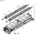
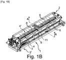
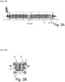
- THE figures 1 to 7 illustrate, at least in part, a heating mixer 1 for composite products based on thermoplastic material(s), in particular factory or construction site waste containing mainly bituminous membranes.
- This mixer 1 has an elongated constitution defining a longitudinal treatment path between an inlet 2 and an outlet 2' and comprises a heated trough 3 in which at least one screw 4, 4' is mounted, preferably two parallel twin screws 4 and 4' and mutually interpenetrating, forming member(s) of dimensional reduction, heating and movement for the products to be treated introduced at the inlet 2, said or each screw 4, 4' comprising a heated and driven support shaft 5, arranged according to the direction of travel DT.
- the thread 4" of the or each screw 4, 4' is an interrupted or discontinuous thread and comprises, over at least a major part of the length of the screw 4, 4' considered, a plurality of first blades 6 in the form of plates flat and smooth, separated from each other axially and radially and all arranged according to a constant screw pitch and with a determined inclination relative to a plane perpendicular to the AV axis of the screw 4, 4' considered.
- the helical thread 4"" of each of the two screws 4 and 4' which rotate in mutually opposite directions of rotation so as to generate a material transport movement from the inlet 2 towards the outlet 2' of the trough 3 (in the direction DT), is therefore constituted by a plurality of blades 6 in the form of planar ring sectors, distinct and separated, secured (by welding for example) with the shaft 5 of the screw 4, 4' concerned on along a helical line. Furthermore, these blades 6 are arranged with mutual spacing and individual angular extension such that longitudinal alignments 7 of blades 6 are constituted.
- each first blade 6 has an angular extension around the shaft considered which is less than 180°, advantageously less than 120°, preferably approximately 90°.
- said first blades 6 are configured and arranged on the support shaft 5 concerned so as to constitute a limited number of alignments 7 of blades 6 in the direction of the AV axis of the screws 4, 4', which are distributed around the periphery of the support shaft 5 and which define between them clear zones 8 extending along the screw 4, 4' between neighboring alignments 7.
- each of the screws 4, 4' appears substantially like an Archimedean screw with a continuous helical thread, but cut in the direction of the AV axis of the shaft 5 to form rectilinear holes parallel to said AV axis.
- the trough 3 has a double envelope and the shaft 5 is a hollow tube, both of which are traversed by a hot fluid (oil).
- the metal blades 6 are relatively thick (for example 8 to 15 mm) so as to guarantee a certain thermal inertia for heating the bitumen in the mass, while catching and "breaking up” the inputs in the form of membranes. (“introduction of hot knife into cold butter” effect).
- the blades 6 offer no grip on the bituminous binder or other.
- the or each screw 4, 4' comprises, over at least part of its length, a plurality of second blades 9 in the form of flat plates, separated from each other and all arranged along planes perpendicular to the axis of the screw 4, 4' considered, that each second blade 9 has an angular extension less than 180°, advantageously less than 120°, preferably approximately 90°, and that said second blades 9 are configured and arranged on the shaft support 5 concerned so as to constitute a limited number of alignments 7' of blades in the direction of the axis AV of the screw 4, 4' and around the shaft 5, clear areas extending between the alignments 7 'neighbors (angularly or circumferentially) along the screw 4, 4'.
- first blades 6 are mounted on the respective shaft 5 with an inclination relative to a plane perpendicular to the AV axis of said shaft, the second blades 9 are shown perpendicular to this AV axis.
- each alignment 7' of second blades 9 extends only over a fraction of the length of the part of the screw 4, 4' comprising them and over a fraction of the periphery of the shaft 5 of the latter and constitutes at least one local group of second blades 9, each group being offset angularly and/or axially relative to each of the other groups and at least one, preferably each, group of second blades 9 of a screw 4, 4' coming into interpenetrating engagement, interstitially, with a corresponding group of second blades 9 of the other screw 4', 4.
- the trough 3 may comprise, on at least part of its internal face, located opposite the longitudinal part(s) of the screw 4, 4' comprising second blades 9, fixed counter-blades, located in parallel and interstitial planes relative to the planes of the second blades 9 and coming into interpenetrating engagement with the second blades 9 during the rotation of the screw 4, 4' considered, each arrangement cooperating by at least two groups of second movable blades 9 belonging respectively to one of the two screws 4, 4', and possibly fixed counter-blades, constituting a privileged shearing module 11.
- the second blades 9 of the screws 4, 4' are not only interfering and interpenetrating between the two screws 4 and 4', but also with fixed counter-blades installed in the trough 3, for example on a support structure mounted interchangeably in trough 3 (not shown).
- the zones of the mixer 1 comprising groups of pluralities of second movable blades 9, and possibly fixed counter-blades, constitute, due to the density of elements forming interpenetrating blades with small air gaps, intense shear modules.
- the mixer 1 may include one or more such module(s), where appropriate distributed along the trough 3.
- a (last) shear module is arranged near the outlet of the mixer 1.
- the or each screw is advantageously made up of longitudinal segments differentiated comprising alternately alignments of first inclined blades 6 and alignments of second perpendicular blades 9.
- first and/or second blades 6, 9 are provided, at their outer free edge 9', with at least one attached scraping structure 12, projecting radially relative to said edge 9' and elastically deformable at least in one radial direction (see figures 4 to 6 ).
- the or each deformable attached structure 12 consists of a plate 12', or a stack of at least two plates 12', with a contour of substantially elliptical shape and comprising cutouts defining a plurality of concentric elliptical rings 13, connected by bridges of material 13' between adjacent rings 13, said structure 12 being mounted on the corresponding blade 6, 9 with an orientation such as the direction of the small half-axis of the contour elliptical passes through the longitudinal axis AV of the support shaft 5.
- the heating mixer 1 according to the invention may include only one screw.
- said mixer 1 comprises two twin parallel screws 4 and 4' whose respective blades 6, 9 intersect intimately over at least part of their height, preferably a majority part, i.e. in at least one zone of mutual meshing of opposite threads of first blades 6 inclined relative to the axis of the support shaft 5, i.e. in at least one zone of mutual interpenetration of second blades 9 perpendicular to the axis of the support shaft 5, advantageously in both types of areas.
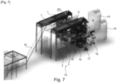
- the invention also has as its object, as shown for example by Figure 7 , an installation 14 for processing and revaluation of composite products thermoplastic base, for example waste incorporating mainly bituminous products, in particular bituminous membranes.
- This installation 14 is characterized in that it comprises, as treatment station(s), at least one mixer 1 as described above, preferably as a first treatment station.
- the installation 14 can include two heating mixers 1 as described above, mounted in parallel, supplied with inputs by a conveyor belt 15 (transporting for example pre-cut waste) and each forming the first station of a channel treatment and revaluation, respectively associated downstream.
- the mixers 1 are installed at height and their liquid or semi-liquid outputs fall through two superimposed grinding stations 16, each formed of a grinder with opposed rollers (whose air gaps are aligned). Between the two stations 16 can be arranged a separator device for solid macroscopic pollutants in the form of a rejection device (not specifically visible) with a movable extractor member (by pivoting). Then, the purified output of macroscopic pollutants can be transferred (for example by a delicerator pump 17) into a refiner 18 with a drum mounted movable eccentrically in a cylindrical enclosure, to then be stored in a tank 19, in the form of upgraded product reusable.
- the invention also relates to a method of controlling a mixer 1 as described above, consisting of driving the screw(s) 4, 4' with a control protocol comprising at least two drive phases causing a movement of the materials in the mixer 1 in the direction DT of the treatment path, separated by at least one contrary training phase, that is to say causing a movement of the treated materials in the direction opposite to the treatment path, the occurrence, the duration and the number of opposite drive phases being either predetermined or a function of values provided by sensors measuring operating parameters, such as for example the drive torque, the composition and/or quality of the products processed, the quantity of materials present in mixer 1.
Landscapes
- Chemical & Material Sciences (AREA)
- Chemical Kinetics & Catalysis (AREA)
- Engineering & Computer Science (AREA)
- Environmental & Geological Engineering (AREA)
- Mechanical Engineering (AREA)
- Processing Of Solid Wastes (AREA)
- Processing And Handling Of Plastics And Other Materials For Molding In General (AREA)
Claims (10)
- Beheizbarer Mischer (1) für Verbundprodukte auf Basis von einem oder mehreren thermoplastischen Materialien, insbesondere von Fabrik- oder Baustellenabfällen, die überwiegend bituminöse Dichtungsbahnen enthalten, wobei der Mischer (1) einen langgestreckten Aufbau aufweist, der einen längs verlaufenden Verarbeitungsweg zwischen einem Einlass (2) und einem Auslass (2') definiert, und einen beheizten Trog (3) umfasst, in dem mindestens eine Schnecke (4, 4') angebracht ist, bevorzugt zwei parallele und ineinander kämmende Doppelschnecken (4 und 4'), die ein bzw. mehrere Zerkleinerungs-, Beheizungs- und Verlagerungsorgan(e) für die zu verarbeitenden Produkte bilden, die an dem Einlass (2) zugeführt werden, wobei die oder jede Schnecke (4, 4') eine beheizte und angetriebene Stützwelle (5) umfasst, die entlang der Wegrichtung (DT) angeordnet ist, Mischer (1), in dem der Schraubengang (4") der oder jeder Schnecke (4, 4') ein unterbrochener oder diskontinuierlicher Schraubengang ist und, über mindestens einen Großteil der Länge der betrachteten Schnecke (4, 4'), eine Vielzahl von ersten Schaufeln (6) in Form von ebenen und glatten Platten umfasst, die axial und radial voneinander getrennt sind und alle gemäß einer konstanten Schraubensteigung und mit einer bestimmten Neigung in Bezug auf eine senkrecht zu der Achse (AV) der betrachteten Schnecke (4, 4') verlaufenden Ebene angeordnet sind,
wobei der Mischer (1) dadurch gekennzeichnet ist, dass die oder jede Schnecke (4, 4'), über mindestens einen Teil ihrer Länge, eine Vielzahl von zweiten Schaufeln (9) in Form von ebenen Platten umfasst, die voneinander getrennt sind und alle entlang von senkrecht zu der Achse der betrachteten Schnecke (4, 4') verlaufenden Ebenen angeordnet sind, dadurch, dass jede zweite Schaufel (9) eine Winkelerstreckung von weniger als 180°, vorteilhafterweise weniger als 120°, bevorzugt etwa 90° aufweist, und dadurch, dass die zweiten Schaufeln (9) auf der betreffenden Stützwelle (5) so ausgestaltet und angeordnet sind, dass sie eine begrenzte Anzahl von Aneinanderreihungen (7') von Schaufel entlang der Richtung der Achse (AV) der Schnecke (4, 4') und um die Welle (5) herum bilden, wobei sich freiliegende Bereiche zwischen den benachbarten Aneinanderreihungen (7') entlang der Schnecke (4, 4') erstrecken. - Mischer nach Anspruch 1, dadurch gekennzeichnet, dass mindestens einige erste und/oder zweite Schaufeln (6, 9), an ihrer freien Außenkante (9'), mit mindestens einer angesetzten Abstreifstruktur (12) versehen sind, die in Bezug auf die Kante (9') radial vorspringt und mindestens entlang einer radialen Richtung elastisch verformbar ist
- Mischer nach Anspruch 1 oder 2, dadurch gekennzeichnet, dass jede erste Schaufel (6) eine Winkelerstreckung um die betrachtete Welle herum aufweist, die weniger als 180°, vorteilhafterweise weniger als 120°, bevorzugt etwa 90° beträgt, und dadurch, dass die ersten Schaufeln (6) auf der betreffenden Stützwelle (5) so ausgestaltet und angeordnet sind, dass sie eine begrenzte Anzahl von Aneinanderreihungen (7) von Schaufeln (6) entlang der Richtung der Achse (AV) der Schnecke (4, 4') bilden, die über den Umfang der Stützwelle (5) verteilt sind und die zwischen sich freiliegende Bereiche (8) bilden, die sich entlang der Schnecke (4, 4') zwischen benachbarten Aneinanderreihungen (7) erstrecken.
- Mischer nach einem der Ansprüche 1 bis 3, dadurch gekennzeichnet, dass sich jede Aneinanderreihung (7') von zweiten Schaufeln (9) nur über einen Bruchteil der Länge des sie umfassenden Teils der Schnecke (4, 4') und über einen Bruchteil des Umfangs von deren Welle (5) erstreckt und mindestens eine lokale Gruppe von zweiten Schaufeln (9) bildet, wobei jede Gruppe winklig und/oder axial in Bezug auf jede der anderen Gruppen versetzt ist und mindestens eine, bevorzugt jede, Gruppe von zweiten Schaufeln (9) einer Schnecke (4, 4') mit einer entsprechenden Gruppe von zweiten Schaufeln (9) der anderen Schnecke (4', 4) interstitiell in kämmenden Eingriff gelangt.
- Mischer nach einem der Ansprüche 1 oder 4, dadurch gekennzeichnet, dass der Trog (3), über mindestens einen Teil seiner Innenseite, der gegenüber dem oder den längs verlaufenden, zweite Schaufeln (9) umfassenden Teil(en) der Schnecke (4, 4') gelegen ist, feststehende Gegenschaufeln umfasst, die in parallelen und interstitiellen Ebenen in Bezug auf Ebenen der zweiten Schaufeln (9) gelegen sind und bei der Drehung der betrachteten Schnecke (4, 4') in kämmenden Eingriff mit den zweiten Schaufeln (9) gelangen, wobei jede zusammenwirkende Anordnung von mindestens zwei Gruppen von zweiten Schaufeln (9), die zu jeweils einer der beiden Schnecken (4, 4') gehören, und eventuell von Gegenschaufeln, ein bevorzugtes Scherungsmodul (11) bildet.
- Mischer nach einem der Ansprüche 1 bis 5, dadurch gekennzeichnet, dass die oder jede Schnecke (4, 4') aus unterschiedlichen längs verlaufenden Segmenten gebildet wird, die abwechselnd Aneinanderreihungen von geneigten ersten Schaufeln (6) und Aneinanderreihungen von senkrechten zweiten Schaufeln (9) umfassen.
- Mischer nach Anspruch 2 oder einem der Ansprüche 3 bis 6, sofern diese abhängig von Anspruch 2 sind, dadurch gekennzeichnet, dass die oder jede verformbare angesetzte Struktur (12) aus einem Plättchen (12') oder aus einem Stapel aus mindestens zwei Plättchen (12') besteht, die eine im Wesentlichen elliptische Kontur haben und Ausschnitte umfassen, die eine Vielzahl von konzentrischen elliptischen Ringen (13) definieren, die durch Materialbrücken (13') zwischen benachbarten Ringen (13) verbunden sind, wobei die Struktur an der entsprechenden Schaufel (6, 9) mit einer solchen Ausrichtung angebracht ist, dass die Richtung der kleinen Halbachse der elliptischen Kontur durch die Längsachse (AV) der entsprechenden Stützwelle (5) verläuft.
- Mischer nach einem der Ansprüche 1 bis 7, dadurch gekennzeichnet, dass er zwei parallele Doppelschnecken (4 und 4') umfasst, deren jeweilige Schaufeln (6, 9) sich über mindestens einen Teil ihrer Höhe, bevorzugt einen überwiegenden Teil, eng verschränken, entweder in mindestens einem Bereich des wechselseitigen Verzahnens von gegensinnigen Schraubengängen von ersten Schaufeln (6), die in Bezug auf die Achse der Stützwelle (5) geneigt sind, oder in mindestens einem Bereich des wechselseitigen Kämmens von zweiten Schaufeln (9), die senkrecht zu der Achse der Stützwelle (5) sind, vorteilhafterweise in den beiden Bereichsarten.
- Anlage (14) zur Verarbeitung und Verwertung von Verbundprodukten auf thermoplastischer Basis, beispielsweise von Abfällen, die überwiegend bituminöse Produkte enthalten, insbesondere bituminöse Dichtungsbahnen, dadurch gekennzeichnet, dass sie, als Verarbeitungsstation(en), mindestens einen Mischer (1) nach einem der Ansprüche 1 bis 8 umfasst, bevorzugt als erste Verarbeitungsstation.
- Verfahren zur Steuerung eines Mischers (1) nach einem der Ansprüche 1 bis 8, das darin besteht, die Schnecke oder Schnecken (4, 4') mit einem Steuerungsprotokoll anzutreiben, das mindestens zwei Antriebsphasen umfasst, die eine Verlagerung der Materialien in dem Mischer (1) entlang der Richtung (DT) des Verarbeitungswegs bewirken und die durch mindestens eine Phase des gegensinnigen, d. h. eine Verlagerung der verarbeiteten Materialien in die zum Verarbeitungsweg entgegengesetzte Richtung bewirkenden, Antriebs getrennt sind, wobei das Vorkommen, die Dauer und die Phasen des gegensinnigen Antriebs entweder vorbestimmt sind oder abhängig von Werten sind, die von Sensoren zur Messung von Betriebsparametern wie beispielsweise dem Antriebmoment, der Zusammensetzung und/oder der Qualität der verarbeiteten Produkte, der Menge von in dem Mischer (1) vorhandenen Materialien, bereitgestellt werden.
Priority Applications (1)
| Application Number | Priority Date | Filing Date | Title |
|---|---|---|---|
| EP24185710.1A EP4480574B1 (de) | 2020-04-22 | 2021-04-01 | Heizmischer für verbundprodukte |
Applications Claiming Priority (2)
| Application Number | Priority Date | Filing Date | Title |
|---|---|---|---|
| FR2003999A FR3109535B1 (fr) | 2020-04-22 | 2020-04-22 | Mélangeur chauffant pour produit composite |
| PCT/EP2021/058730 WO2021213793A1 (fr) | 2020-04-22 | 2021-04-01 | Melangeur chauffant pour produits composites |
Related Child Applications (1)
| Application Number | Title | Priority Date | Filing Date |
|---|---|---|---|
| EP24185710.1A Division EP4480574B1 (de) | 2020-04-22 | 2021-04-01 | Heizmischer für verbundprodukte |
Publications (2)
| Publication Number | Publication Date |
|---|---|
| EP4139032A1 EP4139032A1 (de) | 2023-03-01 |
| EP4139032B1 true EP4139032B1 (de) | 2024-07-24 |
Family
ID=71111613
Family Applications (2)
| Application Number | Title | Priority Date | Filing Date |
|---|---|---|---|
| EP21718057.9A Active EP4139032B1 (de) | 2020-04-22 | 2021-04-01 | Beheizbarer mischer für verbundwerkstoffe |
| EP24185710.1A Active EP4480574B1 (de) | 2020-04-22 | 2021-04-01 | Heizmischer für verbundprodukte |
Family Applications After (1)
| Application Number | Title | Priority Date | Filing Date |
|---|---|---|---|
| EP24185710.1A Active EP4480574B1 (de) | 2020-04-22 | 2021-04-01 | Heizmischer für verbundprodukte |
Country Status (8)
| Country | Link |
|---|---|
| US (1) | US20230201779A1 (de) |
| EP (2) | EP4139032B1 (de) |
| CA (1) | CA3175519A1 (de) |
| ES (1) | ES2992312T3 (de) |
| FR (1) | FR3109535B1 (de) |
| PL (1) | PL4139032T3 (de) |
| PT (1) | PT4139032T (de) |
| WO (1) | WO2021213793A1 (de) |
Families Citing this family (5)
| Publication number | Priority date | Publication date | Assignee | Title |
|---|---|---|---|---|
| FR3125244B1 (fr) | 2021-07-16 | 2025-11-07 | Soprema | Mélangeur chauffant pour produits composites à sortie régulée |
| CN114405318A (zh) * | 2022-01-20 | 2022-04-29 | 广西北投交通养护科技集团有限公司 | 一种智能感应型改性沥青搅拌装置及其使用方法 |
| FR3147116B1 (fr) | 2023-04-03 | 2025-04-04 | Soprema | Procédé et installation de broyage ou de fragmentation de produits bitumineux |
| CN117482838B (zh) * | 2024-01-02 | 2024-03-15 | 水润天府新材料有限公司 | 一种布敦岩沥青改性混合料生产设备及工艺 |
| CN119158483A (zh) * | 2024-11-20 | 2024-12-20 | 福建白鹰新材料科技有限公司 | 一种染整助剂用恒温处理设备及工艺 |
Family Cites Families (14)
| Publication number | Priority date | Publication date | Assignee | Title |
|---|---|---|---|---|
| JPS62172179A (ja) * | 1986-01-25 | 1987-07-29 | 株式会社クボタ | ら旋搬送式乾燥機 |
| JPS63209547A (ja) * | 1987-02-25 | 1988-08-31 | Tsukishima Kikai Co Ltd | 処理槽のワイピング装置 |
| DE19531189C2 (de) * | 1995-08-24 | 1999-03-04 | Vakumix Ruehr Und Homogenisier | Abstreifvorrichtung |
| EP0988952A1 (de) | 1998-09-22 | 2000-03-29 | Performance Roof Systems S.A. en abrégé P.R.S. | Membranwiederverwendungsverfahren und Extruder dafür |
| BE1015015A3 (fr) | 2002-06-28 | 2004-08-03 | Performance Roof Systems S A E | Procede et unite de recyclage d'une membrane bitumineuse. |
| CN100579436C (zh) * | 2006-05-22 | 2010-01-13 | 安迪·铭棻·童 | 一种用于环保马桶的搅拌装置及处理装置 |
| NL1033423C2 (nl) | 2007-02-19 | 2008-08-20 | Esha Group B V | Inrichting en werkwijze voor het recyclen van bitumineus dakafval. |
| NL1034022C2 (nl) * | 2007-06-22 | 2008-12-23 | Goudsche Machf B V | Inrichting voor warmtewisseling met radiaal mengen. |
| ITTO20080047A1 (it) | 2008-01-18 | 2009-07-19 | Euroline Srl | Macchina e metodo per sminuzzare porzioni di materiale bituminoso in granuli riciclabili |
| DE102008045652A1 (de) * | 2008-09-03 | 2010-05-20 | Alco-Food-Machines Gmbh & Co. Kg | Lebensmittelmischanlage zur Verarbeitung von Lebensmitteln |
| US8579496B2 (en) * | 2010-10-05 | 2013-11-12 | Whirlpool Corporation | Stand mixer wiping beater |
| WO2017018037A1 (ja) * | 2015-07-29 | 2017-02-02 | 株式会社新日南 | 原料を加熱又は冷却する装置 |
| FR3051202B1 (fr) * | 2016-05-10 | 2019-03-22 | Colas | Dispositif pour le recyclage in situ de materiaux d'une chaussee de circulation et concasseur specialement adapte |
| FR3060417B1 (fr) * | 2016-12-15 | 2019-05-24 | Lab Sa | Reacteur de reactivation de solides |
-
2020
- 2020-04-22 FR FR2003999A patent/FR3109535B1/fr active Active
-
2021
- 2021-04-01 EP EP21718057.9A patent/EP4139032B1/de active Active
- 2021-04-01 EP EP24185710.1A patent/EP4480574B1/de active Active
- 2021-04-01 ES ES21718057T patent/ES2992312T3/es active Active
- 2021-04-01 PT PT217180579T patent/PT4139032T/pt unknown
- 2021-04-01 US US17/920,358 patent/US20230201779A1/en not_active Abandoned
- 2021-04-01 PL PL21718057.9T patent/PL4139032T3/pl unknown
- 2021-04-01 WO PCT/EP2021/058730 patent/WO2021213793A1/fr not_active Ceased
- 2021-04-01 CA CA3175519A patent/CA3175519A1/fr active Pending
Also Published As
| Publication number | Publication date |
|---|---|
| EP4480574A1 (de) | 2024-12-25 |
| WO2021213793A1 (fr) | 2021-10-28 |
| US20230201779A1 (en) | 2023-06-29 |
| EP4139032A1 (de) | 2023-03-01 |
| FR3109535B1 (fr) | 2023-04-14 |
| FR3109535A1 (fr) | 2021-10-29 |
| PT4139032T (pt) | 2024-10-22 |
| EP4480574B1 (de) | 2026-02-18 |
| ES2992312T3 (es) | 2024-12-11 |
| CA3175519A1 (fr) | 2021-10-28 |
| PL4139032T3 (pl) | 2025-02-17 |
Similar Documents
| Publication | Publication Date | Title |
|---|---|---|
| EP4139032B1 (de) | Beheizbarer mischer für verbundwerkstoffe | |
| EP4139105B1 (de) | Anlage und verfahren zur behandlung von verbundwerkstoffen auf basis von thermoplastischen kunststoffen | |
| RU2264292C2 (ru) | Устройство для уменьшения объема, занимаемого поступающими на переплавку отходами полимерных материалов, и способ уменьшения занимаемого ими объёма, осуществляемый с использованием этого устройства | |
| EP2473294B1 (de) | Recycling-verfahren und -anlage für gipsabfall | |
| US7159804B2 (en) | Unit and method for recycling a bituminous membrane | |
| JP7361208B2 (ja) | 瀝青廃棄膜製品などの瀝青廃棄製品のリサイクルプロセス | |
| WO1995008393A1 (en) | Glass shearing apparatus and method | |
| EP4370299B1 (de) | Beheizbarer mischer für verbundwerkstoffe mit gesteuertem ausgang | |
| CA3175511A1 (fr) | Raffineur, installation et procede pour le traitement de produits composites | |
| EP1074303A1 (de) | Trommel für einen Abfallbehandlungsapparat und entsprechender Apparat | |
| WO2005075742A1 (fr) | Procede et dispositif de mise en temperature de granulats et/ou d'enrobes routiers, notamment d'enrobes usages a recycler | |
| RU2397030C2 (ru) | Способ утилизации бытовых и промышленных отходов | |
| KR20160130375A (ko) | 잘게 잘린 플라스틱으로부터 불순물을 제거하기 위한 장치 | |
| FR2460551A1 (fr) | Procede et dispositif pour la fragmentation de batteries | |
| WO2024208606A1 (fr) | Procédé et installation de broyage ou de fragmentation de produits bitumineux | |
| RU2435664C1 (ru) | Устройство для измельчения пластичных материалов | |
| RU2583679C1 (ru) | Способ принудительного, интенсивного таяния снега, засорённого твердыми включениями и бытовым мусором | |
| RU2188890C1 (ru) | Способ удаления снежно-ледяной массы, собираемой с территории мегаполиса, и устройство для осуществления этого способа | |
| FR3032133A1 (fr) | Machine et installation de purification des granulats issus du beton | |
| FR2834714A1 (fr) | Installation perfectionnee de compostage de matiere organique | |
| UA56781A (uk) | Спосіб відновлення покрівель з бітумвмісних матеріалів |
Legal Events
| Date | Code | Title | Description |
|---|---|---|---|
| STAA | Information on the status of an ep patent application or granted ep patent |
Free format text: STATUS: UNKNOWN |
|
| STAA | Information on the status of an ep patent application or granted ep patent |
Free format text: STATUS: THE INTERNATIONAL PUBLICATION HAS BEEN MADE |
|
| PUAI | Public reference made under article 153(3) epc to a published international application that has entered the european phase |
Free format text: ORIGINAL CODE: 0009012 |
|
| STAA | Information on the status of an ep patent application or granted ep patent |
Free format text: STATUS: REQUEST FOR EXAMINATION WAS MADE |
|
| 17P | Request for examination filed |
Effective date: 20221117 |
|
| AK | Designated contracting states |
Kind code of ref document: A1 Designated state(s): AL AT BE BG CH CY CZ DE DK EE ES FI FR GB GR HR HU IE IS IT LI LT LU LV MC MK MT NL NO PL PT RO RS SE SI SK SM TR |
|
| DAV | Request for validation of the european patent (deleted) | ||
| DAX | Request for extension of the european patent (deleted) | ||
| P01 | Opt-out of the competence of the unified patent court (upc) registered |
Effective date: 20230622 |
|
| REG | Reference to a national code |
Ref country code: DE Ref country code: DE Ref legal event code: R079 Ref document number: 602021016148 Country of ref document: DE Free format text: PREVIOUS MAIN CLASS: B01F0015060000 Ipc: B01F0027091000 |
|
| GRAP | Despatch of communication of intention to grant a patent |
Free format text: ORIGINAL CODE: EPIDOSNIGR1 |
|
| STAA | Information on the status of an ep patent application or granted ep patent |
Free format text: STATUS: GRANT OF PATENT IS INTENDED |
|
| RIC1 | Information provided on ipc code assigned before grant |
Ipc: B29L 31/10 20060101ALN20240131BHEP Ipc: B29K 95/00 20060101ALN20240131BHEP Ipc: B29B 17/04 20060101ALI20240131BHEP Ipc: B01F 35/95 20220101ALI20240131BHEP Ipc: B01F 35/92 20220101ALI20240131BHEP Ipc: B01F 27/723 20220101ALI20240131BHEP Ipc: B01F 27/702 20220101ALI20240131BHEP Ipc: B01F 27/091 20220101AFI20240131BHEP |
|
| INTG | Intention to grant announced |
Effective date: 20240219 |
|
| GRAS | Grant fee paid |
Free format text: ORIGINAL CODE: EPIDOSNIGR3 |
|
| GRAA | (expected) grant |
Free format text: ORIGINAL CODE: 0009210 |
|
| STAA | Information on the status of an ep patent application or granted ep patent |
Free format text: STATUS: THE PATENT HAS BEEN GRANTED |
|
| RAP3 | Party data changed (applicant data changed or rights of an application transferred) |
Owner name: SOPREMA |
|
| AK | Designated contracting states |
Kind code of ref document: B1 Designated state(s): AL AT BE BG CH CY CZ DE DK EE ES FI FR GB GR HR HU IE IS IT LI LT LU LV MC MK MT NL NO PL PT RO RS SE SI SK SM TR |
|
| REG | Reference to a national code |
Ref country code: GB Ref legal event code: FG4D Free format text: NOT ENGLISH |
|
| REG | Reference to a national code |
Ref country code: CH Ref legal event code: EP |
|
| REG | Reference to a national code |
Ref country code: IE Ref legal event code: FG4D Free format text: LANGUAGE OF EP DOCUMENT: FRENCH Ref country code: DE Ref legal event code: R096 Ref document number: 602021016148 Country of ref document: DE |
|
| REG | Reference to a national code |
Ref country code: PT Ref legal event code: SC4A Ref document number: 4139032 Country of ref document: PT Date of ref document: 20241022 Kind code of ref document: T Free format text: AVAILABILITY OF NATIONAL TRANSLATION Effective date: 20241016 |
|
| REG | Reference to a national code |
Ref country code: NL Ref legal event code: FP |
|
| REG | Reference to a national code |
Ref country code: LT Ref legal event code: MG9D |
|
| REG | Reference to a national code |
Ref country code: ES Ref legal event code: FG2A Ref document number: 2992312 Country of ref document: ES Kind code of ref document: T3 Effective date: 20241211 |
|
| REG | Reference to a national code |
Ref country code: AT Ref legal event code: MK05 Ref document number: 1705812 Country of ref document: AT Kind code of ref document: T Effective date: 20240724 |
|
| PG25 | Lapsed in a contracting state [announced via postgrant information from national office to epo] |
Ref country code: NO Free format text: LAPSE BECAUSE OF FAILURE TO SUBMIT A TRANSLATION OF THE DESCRIPTION OR TO PAY THE FEE WITHIN THE PRESCRIBED TIME-LIMIT Effective date: 20241024 |
|
| PG25 | Lapsed in a contracting state [announced via postgrant information from national office to epo] |
Ref country code: FI Free format text: LAPSE BECAUSE OF FAILURE TO SUBMIT A TRANSLATION OF THE DESCRIPTION OR TO PAY THE FEE WITHIN THE PRESCRIBED TIME-LIMIT Effective date: 20240724 Ref country code: GR Free format text: LAPSE BECAUSE OF FAILURE TO SUBMIT A TRANSLATION OF THE DESCRIPTION OR TO PAY THE FEE WITHIN THE PRESCRIBED TIME-LIMIT Effective date: 20241025 |
|
| PG25 | Lapsed in a contracting state [announced via postgrant information from national office to epo] |
Ref country code: BG Free format text: LAPSE BECAUSE OF FAILURE TO SUBMIT A TRANSLATION OF THE DESCRIPTION OR TO PAY THE FEE WITHIN THE PRESCRIBED TIME-LIMIT Effective date: 20240724 |
|
| PG25 | Lapsed in a contracting state [announced via postgrant information from national office to epo] |
Ref country code: LV Free format text: LAPSE BECAUSE OF FAILURE TO SUBMIT A TRANSLATION OF THE DESCRIPTION OR TO PAY THE FEE WITHIN THE PRESCRIBED TIME-LIMIT Effective date: 20240724 |
|
| PG25 | Lapsed in a contracting state [announced via postgrant information from national office to epo] |
Ref country code: IS Free format text: LAPSE BECAUSE OF FAILURE TO SUBMIT A TRANSLATION OF THE DESCRIPTION OR TO PAY THE FEE WITHIN THE PRESCRIBED TIME-LIMIT Effective date: 20241124 Ref country code: AT Free format text: LAPSE BECAUSE OF FAILURE TO SUBMIT A TRANSLATION OF THE DESCRIPTION OR TO PAY THE FEE WITHIN THE PRESCRIBED TIME-LIMIT Effective date: 20240724 |
|
| PG25 | Lapsed in a contracting state [announced via postgrant information from national office to epo] |
Ref country code: HR Free format text: LAPSE BECAUSE OF FAILURE TO SUBMIT A TRANSLATION OF THE DESCRIPTION OR TO PAY THE FEE WITHIN THE PRESCRIBED TIME-LIMIT Effective date: 20240724 |
|
| PG25 | Lapsed in a contracting state [announced via postgrant information from national office to epo] |
Ref country code: RS Free format text: LAPSE BECAUSE OF FAILURE TO SUBMIT A TRANSLATION OF THE DESCRIPTION OR TO PAY THE FEE WITHIN THE PRESCRIBED TIME-LIMIT Effective date: 20241024 |
|
| PG25 | Lapsed in a contracting state [announced via postgrant information from national office to epo] |
Ref country code: RS Free format text: LAPSE BECAUSE OF FAILURE TO SUBMIT A TRANSLATION OF THE DESCRIPTION OR TO PAY THE FEE WITHIN THE PRESCRIBED TIME-LIMIT Effective date: 20241024 Ref country code: NO Free format text: LAPSE BECAUSE OF FAILURE TO SUBMIT A TRANSLATION OF THE DESCRIPTION OR TO PAY THE FEE WITHIN THE PRESCRIBED TIME-LIMIT Effective date: 20241024 Ref country code: LV Free format text: LAPSE BECAUSE OF FAILURE TO SUBMIT A TRANSLATION OF THE DESCRIPTION OR TO PAY THE FEE WITHIN THE PRESCRIBED TIME-LIMIT Effective date: 20240724 Ref country code: IS Free format text: LAPSE BECAUSE OF FAILURE TO SUBMIT A TRANSLATION OF THE DESCRIPTION OR TO PAY THE FEE WITHIN THE PRESCRIBED TIME-LIMIT Effective date: 20241124 Ref country code: HR Free format text: LAPSE BECAUSE OF FAILURE TO SUBMIT A TRANSLATION OF THE DESCRIPTION OR TO PAY THE FEE WITHIN THE PRESCRIBED TIME-LIMIT Effective date: 20240724 Ref country code: GR Free format text: LAPSE BECAUSE OF FAILURE TO SUBMIT A TRANSLATION OF THE DESCRIPTION OR TO PAY THE FEE WITHIN THE PRESCRIBED TIME-LIMIT Effective date: 20241025 Ref country code: FI Free format text: LAPSE BECAUSE OF FAILURE TO SUBMIT A TRANSLATION OF THE DESCRIPTION OR TO PAY THE FEE WITHIN THE PRESCRIBED TIME-LIMIT Effective date: 20240724 Ref country code: BG Free format text: LAPSE BECAUSE OF FAILURE TO SUBMIT A TRANSLATION OF THE DESCRIPTION OR TO PAY THE FEE WITHIN THE PRESCRIBED TIME-LIMIT Effective date: 20240724 Ref country code: AT Free format text: LAPSE BECAUSE OF FAILURE TO SUBMIT A TRANSLATION OF THE DESCRIPTION OR TO PAY THE FEE WITHIN THE PRESCRIBED TIME-LIMIT Effective date: 20240724 |
|
| PG25 | Lapsed in a contracting state [announced via postgrant information from national office to epo] |
Ref country code: DK Free format text: LAPSE BECAUSE OF FAILURE TO SUBMIT A TRANSLATION OF THE DESCRIPTION OR TO PAY THE FEE WITHIN THE PRESCRIBED TIME-LIMIT Effective date: 20240724 Ref country code: RO Free format text: LAPSE BECAUSE OF FAILURE TO SUBMIT A TRANSLATION OF THE DESCRIPTION OR TO PAY THE FEE WITHIN THE PRESCRIBED TIME-LIMIT Effective date: 20240724 Ref country code: SM Free format text: LAPSE BECAUSE OF FAILURE TO SUBMIT A TRANSLATION OF THE DESCRIPTION OR TO PAY THE FEE WITHIN THE PRESCRIBED TIME-LIMIT Effective date: 20240724 |
|
| PG25 | Lapsed in a contracting state [announced via postgrant information from national office to epo] |
Ref country code: EE Free format text: LAPSE BECAUSE OF FAILURE TO SUBMIT A TRANSLATION OF THE DESCRIPTION OR TO PAY THE FEE WITHIN THE PRESCRIBED TIME-LIMIT Effective date: 20240724 |
|
| PG25 | Lapsed in a contracting state [announced via postgrant information from national office to epo] |
Ref country code: CZ Free format text: LAPSE BECAUSE OF FAILURE TO SUBMIT A TRANSLATION OF THE DESCRIPTION OR TO PAY THE FEE WITHIN THE PRESCRIBED TIME-LIMIT Effective date: 20240724 |
|
| REG | Reference to a national code |
Ref country code: DE Ref legal event code: R097 Ref document number: 602021016148 Country of ref document: DE |
|
| PG25 | Lapsed in a contracting state [announced via postgrant information from national office to epo] |
Ref country code: SK Free format text: LAPSE BECAUSE OF FAILURE TO SUBMIT A TRANSLATION OF THE DESCRIPTION OR TO PAY THE FEE WITHIN THE PRESCRIBED TIME-LIMIT Effective date: 20240724 |
|
| PGFP | Annual fee paid to national office [announced via postgrant information from national office to epo] |
Ref country code: NL Payment date: 20250427 Year of fee payment: 5 |
|
| PLBE | No opposition filed within time limit |
Free format text: ORIGINAL CODE: 0009261 |
|
| STAA | Information on the status of an ep patent application or granted ep patent |
Free format text: STATUS: NO OPPOSITION FILED WITHIN TIME LIMIT |
|
| 26N | No opposition filed |
Effective date: 20250425 |
|
| PGFP | Annual fee paid to national office [announced via postgrant information from national office to epo] |
Ref country code: DE Payment date: 20250429 Year of fee payment: 5 |
|
| PGFP | Annual fee paid to national office [announced via postgrant information from national office to epo] |
Ref country code: ES Payment date: 20250505 Year of fee payment: 5 |
|
| PGFP | Annual fee paid to national office [announced via postgrant information from national office to epo] |
Ref country code: BE Payment date: 20250428 Year of fee payment: 5 Ref country code: IT Payment date: 20250422 Year of fee payment: 5 |
|
| PGFP | Annual fee paid to national office [announced via postgrant information from national office to epo] |
Ref country code: FR Payment date: 20250425 Year of fee payment: 5 |
|
| PGFP | Annual fee paid to national office [announced via postgrant information from national office to epo] |
Ref country code: CH Payment date: 20250501 Year of fee payment: 5 |
|
| PG25 | Lapsed in a contracting state [announced via postgrant information from national office to epo] |
Ref country code: SE Free format text: LAPSE BECAUSE OF FAILURE TO SUBMIT A TRANSLATION OF THE DESCRIPTION OR TO PAY THE FEE WITHIN THE PRESCRIBED TIME-LIMIT Effective date: 20240724 |
|
| PG25 | Lapsed in a contracting state [announced via postgrant information from national office to epo] |
Ref country code: LU Free format text: LAPSE BECAUSE OF NON-PAYMENT OF DUE FEES Effective date: 20250401 |
|
| PG25 | Lapsed in a contracting state [announced via postgrant information from national office to epo] |
Ref country code: MC Free format text: LAPSE BECAUSE OF FAILURE TO SUBMIT A TRANSLATION OF THE DESCRIPTION OR TO PAY THE FEE WITHIN THE PRESCRIBED TIME-LIMIT Effective date: 20240724 |
|
| GBPC | Gb: european patent ceased through non-payment of renewal fee |
Effective date: 20250401 |
|
| PG25 | Lapsed in a contracting state [announced via postgrant information from national office to epo] |
Ref country code: GB Free format text: LAPSE BECAUSE OF NON-PAYMENT OF DUE FEES Effective date: 20250401 |
|
| PG25 | Lapsed in a contracting state [announced via postgrant information from national office to epo] |
Ref country code: IE Free format text: LAPSE BECAUSE OF NON-PAYMENT OF DUE FEES Effective date: 20250401 |
|
| PGFP | Annual fee paid to national office [announced via postgrant information from national office to epo] |
Ref country code: PT Payment date: 20260319 Year of fee payment: 6 |
|
| PGFP | Annual fee paid to national office [announced via postgrant information from national office to epo] |
Ref country code: PL Payment date: 20260320 Year of fee payment: 6 |