EP4137301A1 - Fresnel-linsenform und herstellungsverfahren dafür, und herstellungsverfahren für eine fresnel-linse - Google Patents
Fresnel-linsenform und herstellungsverfahren dafür, und herstellungsverfahren für eine fresnel-linse Download PDFInfo
- Publication number
- EP4137301A1 EP4137301A1 EP20930924.4A EP20930924A EP4137301A1 EP 4137301 A1 EP4137301 A1 EP 4137301A1 EP 20930924 A EP20930924 A EP 20930924A EP 4137301 A1 EP4137301 A1 EP 4137301A1
- Authority
- EP
- European Patent Office
- Prior art keywords
- fresnel lens
- strip
- lens
- annular
- annular strip
- Prior art date
- Legal status (The legal status is an assumption and is not a legal conclusion. Google has not performed a legal analysis and makes no representation as to the accuracy of the status listed.)
- Pending
Links
- 238000004519 manufacturing process Methods 0.000 title claims abstract description 59
- 230000003287 optical effect Effects 0.000 claims abstract description 85
- 238000012545 processing Methods 0.000 claims abstract description 27
- 238000000034 method Methods 0.000 claims abstract description 25
- 238000000227 grinding Methods 0.000 claims description 14
- 238000003801 milling Methods 0.000 claims description 11
- 238000007514 turning Methods 0.000 claims description 10
- 238000001723 curing Methods 0.000 claims description 8
- 239000003292 glue Substances 0.000 claims description 8
- 239000011248 coating agent Substances 0.000 claims description 6
- 238000000576 coating method Methods 0.000 claims description 6
- 238000007731 hot pressing Methods 0.000 claims description 5
- 230000001070 adhesive effect Effects 0.000 claims description 4
- 239000007788 liquid Substances 0.000 claims description 4
- 238000000465 moulding Methods 0.000 claims description 4
- 238000006243 chemical reaction Methods 0.000 claims description 3
- 238000003847 radiation curing Methods 0.000 claims description 3
- 239000000853 adhesive Substances 0.000 claims description 2
- 238000001179 sorption measurement Methods 0.000 claims description 2
- 238000001029 thermal curing Methods 0.000 claims description 2
- 238000013461 design Methods 0.000 description 21
- 239000010408 film Substances 0.000 description 13
- 230000008569 process Effects 0.000 description 13
- 238000003825 pressing Methods 0.000 description 10
- 239000012788 optical film Substances 0.000 description 8
- 238000005516 engineering process Methods 0.000 description 7
- 238000003475 lamination Methods 0.000 description 7
- 229910052751 metal Inorganic materials 0.000 description 6
- 239000002184 metal Substances 0.000 description 6
- 239000000243 solution Substances 0.000 description 5
- 239000000919 ceramic Substances 0.000 description 4
- 239000002861 polymer material Substances 0.000 description 4
- 239000002994 raw material Substances 0.000 description 4
- 238000005094 computer simulation Methods 0.000 description 3
- 230000001788 irregular Effects 0.000 description 3
- 239000000463 material Substances 0.000 description 3
- 229910000838 Al alloy Inorganic materials 0.000 description 2
- 229920000049 Carbon (fiber) Polymers 0.000 description 2
- 229910000881 Cu alloy Inorganic materials 0.000 description 2
- 229910000861 Mg alloy Inorganic materials 0.000 description 2
- SNAAJJQQZSMGQD-UHFFFAOYSA-N aluminum magnesium Chemical compound [Mg].[Al] SNAAJJQQZSMGQD-UHFFFAOYSA-N 0.000 description 2
- 239000004917 carbon fiber Substances 0.000 description 2
- 238000005520 cutting process Methods 0.000 description 2
- 238000011161 development Methods 0.000 description 2
- 230000000694 effects Effects 0.000 description 2
- 238000001746 injection moulding Methods 0.000 description 2
- 239000007769 metal material Substances 0.000 description 2
- VNWKTOKETHGBQD-UHFFFAOYSA-N methane Chemical compound C VNWKTOKETHGBQD-UHFFFAOYSA-N 0.000 description 2
- 238000012986 modification Methods 0.000 description 2
- 230000004048 modification Effects 0.000 description 2
- 239000011224 oxide ceramic Substances 0.000 description 2
- 229910052574 oxide ceramic Inorganic materials 0.000 description 2
- TWNQGVIAIRXVLR-UHFFFAOYSA-N oxo(oxoalumanyloxy)alumane Chemical compound O=[Al]O[Al]=O TWNQGVIAIRXVLR-UHFFFAOYSA-N 0.000 description 2
- 238000005498 polishing Methods 0.000 description 2
- -1 polytetrafluoroethylene Polymers 0.000 description 2
- 229920001343 polytetrafluoroethylene Polymers 0.000 description 2
- 239000004810 polytetrafluoroethylene Substances 0.000 description 2
- 239000010935 stainless steel Substances 0.000 description 2
- 229910001220 stainless steel Inorganic materials 0.000 description 2
- 239000000758 substrate Substances 0.000 description 2
- 238000010023 transfer printing Methods 0.000 description 2
- 238000004026 adhesive bonding Methods 0.000 description 1
- 230000009286 beneficial effect Effects 0.000 description 1
- 230000015572 biosynthetic process Effects 0.000 description 1
- 239000003795 chemical substances by application Substances 0.000 description 1
- 238000004891 communication Methods 0.000 description 1
- 230000000295 complement effect Effects 0.000 description 1
- 239000008358 core component Substances 0.000 description 1
- 238000013007 heat curing Methods 0.000 description 1
- 238000003384 imaging method Methods 0.000 description 1
- 230000003993 interaction Effects 0.000 description 1
- 238000003754 machining Methods 0.000 description 1
- 150000002739 metals Chemical class 0.000 description 1
- 238000002360 preparation method Methods 0.000 description 1
- 238000005086 pumping Methods 0.000 description 1
- 238000000926 separation method Methods 0.000 description 1
- 238000012546 transfer Methods 0.000 description 1
Images


Classifications
-
- B—PERFORMING OPERATIONS; TRANSPORTING
- B29—WORKING OF PLASTICS; WORKING OF SUBSTANCES IN A PLASTIC STATE IN GENERAL
- B29D—PRODUCING PARTICULAR ARTICLES FROM PLASTICS OR FROM SUBSTANCES IN A PLASTIC STATE
- B29D11/00—Producing optical elements, e.g. lenses or prisms
- B29D11/00009—Production of simple or compound lenses
- B29D11/0048—Moulds for lenses
- B29D11/00519—Reusable moulds
-
- B—PERFORMING OPERATIONS; TRANSPORTING
- B29—WORKING OF PLASTICS; WORKING OF SUBSTANCES IN A PLASTIC STATE IN GENERAL
- B29C—SHAPING OR JOINING OF PLASTICS; SHAPING OF MATERIAL IN A PLASTIC STATE, NOT OTHERWISE PROVIDED FOR; AFTER-TREATMENT OF THE SHAPED PRODUCTS, e.g. REPAIRING
- B29C33/00—Moulds or cores; Details thereof or accessories therefor
- B29C33/30—Mounting, exchanging or centering
- B29C33/301—Modular mould systems [MMS], i.e. moulds built up by stacking mould elements, e.g. plates, blocks, rods
- B29C33/302—Assembling a large number of mould elements to constitute one cavity
-
- B—PERFORMING OPERATIONS; TRANSPORTING
- B29—WORKING OF PLASTICS; WORKING OF SUBSTANCES IN A PLASTIC STATE IN GENERAL
- B29C—SHAPING OR JOINING OF PLASTICS; SHAPING OF MATERIAL IN A PLASTIC STATE, NOT OTHERWISE PROVIDED FOR; AFTER-TREATMENT OF THE SHAPED PRODUCTS, e.g. REPAIRING
- B29C33/00—Moulds or cores; Details thereof or accessories therefor
- B29C33/38—Moulds or cores; Details thereof or accessories therefor characterised by the material or the manufacturing process
- B29C33/3835—Designing moulds, e.g. using CAD-CAM
-
- B—PERFORMING OPERATIONS; TRANSPORTING
- B29—WORKING OF PLASTICS; WORKING OF SUBSTANCES IN A PLASTIC STATE IN GENERAL
- B29C—SHAPING OR JOINING OF PLASTICS; SHAPING OF MATERIAL IN A PLASTIC STATE, NOT OTHERWISE PROVIDED FOR; AFTER-TREATMENT OF THE SHAPED PRODUCTS, e.g. REPAIRING
- B29C33/00—Moulds or cores; Details thereof or accessories therefor
- B29C33/38—Moulds or cores; Details thereof or accessories therefor characterised by the material or the manufacturing process
- B29C33/3842—Manufacturing moulds, e.g. shaping the mould surface by machining
-
- B—PERFORMING OPERATIONS; TRANSPORTING
- B29—WORKING OF PLASTICS; WORKING OF SUBSTANCES IN A PLASTIC STATE IN GENERAL
- B29C—SHAPING OR JOINING OF PLASTICS; SHAPING OF MATERIAL IN A PLASTIC STATE, NOT OTHERWISE PROVIDED FOR; AFTER-TREATMENT OF THE SHAPED PRODUCTS, e.g. REPAIRING
- B29C33/00—Moulds or cores; Details thereof or accessories therefor
- B29C33/42—Moulds or cores; Details thereof or accessories therefor characterised by the shape of the moulding surface, e.g. ribs or grooves
-
- B—PERFORMING OPERATIONS; TRANSPORTING
- B29—WORKING OF PLASTICS; WORKING OF SUBSTANCES IN A PLASTIC STATE IN GENERAL
- B29D—PRODUCING PARTICULAR ARTICLES FROM PLASTICS OR FROM SUBSTANCES IN A PLASTIC STATE
- B29D11/00—Producing optical elements, e.g. lenses or prisms
- B29D11/00009—Production of simple or compound lenses
- B29D11/00269—Fresnel lenses
Definitions
- the present application relates to the technical field of optics, and in particular to a Fresnel lens mold and manufacturing method therefor, and a manufacturing method for Fresnel lens.
- a Fresnel lens is composed of several optical structures arranged in sequence.
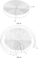
- the Fresnel lens can be an optical structure with regular shape. As shown in FIG. 1 , a Fresnel lens is formed by the arrangement of strips of concentric annular optical structures.
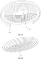
- the Fresnel lens may also be composed of optical structures with irregular shapes, as shown in FIG. 2 and FIG. 3 .
- the most commonly used manufacturing method of Fresnel lens is only adapted for Fresnel lens with small aperture, which is specifically in that: the annulus is machined on the flat blank by a precision lathe to make a flat mold, and the circular annulus on the flat mold is copied to the substrate by hot-pressing, pouring, molding, injection molding, ultraviolet curing and etc..
- the core optical element of the required rectangular laser TV screen is the rectangular Fresnel lens section, which is cut out from the circular Fresnel. If the required diameter of the circular Fresnel lens is more than 4 meters, a Fresnel lens mold with the corresponding size is needed, and the production of the Fresnel lens mold cannot be realized by using the existing machine tools.
- Chinese patent CN103895219B discloses a tapered roller for making Fresnel lenses, which solves the limitation of lathe size to the manufacturing size of flat molds.
- a tapered roller mold can be processed by a smaller lathe, and the Fresnel lens with a larger size can be manufactured by the tapered roller mold.
- the tapered roller itself can be regarded as a superposition of concentric rings with different diameters, which can be used to make a Fresnel lens composed of several regular optical structures.
- this technical solution cannot produce a Fresnel lens formed by a non-concentric optical structure, and the size of the Fresnel lens mold that can be processed is also limited.
- Chinese patent application CN108890944A discloses a mold for manufacturing a Fresnel lens and a production method thereof.
- the mold includes a pressing plate and a base plate at a lower end of the pressing plate. Multiple annular grooves with different diameters are distributed on the base plate, and the adjacent grooves have different depths and inclination angles.
- the lower end of the pressing plate is provided with a protruding portion that fits with the groove on the base plate;
- the Fresnel lens annular strip is processed on the surface of small pieces of metal strips by a numerical control machine, and then the small pieces of metal strips are spliced and combined into a substrate blank.
- the residual quantity reserved on the surface of the blank is removed by a lathe and a cutter, and the Fresnel lens molding template is obtained by grinding with a grinding machine to remove thorns.
- This method can't realize the production of large-size Fresnel lens molds.
- Large-size Fresnel lens needs to be formed by splicing. The existence of splicing seam seriously affects the performance of Fresnel lens, so it can't be used in electronic display and other situation that require high apparent quality of Fresnel lens.
- an object of the present application is to provide a Fresnel lens mold, which solves the problem that the Fresnel lens with super large size and irregular shape cannot be manufactured in the conventional technology.
- a Fresnel lens mold includes stacked strips, where the strip is bendable, and an optical structure, which is the same as a lens structure on a corresponding annular strip of a designed Fresnel lens, is provided at one edge of the strip.
- the Fresnel lens mold further includes a reference unit, and the strip is stacked on a contour surface of the reference unit based on the reference unit.
- a contour shape of the reference unit is the same as an annular strip shape of the corresponding area of the Fresnel lens.
- the strip is stacked on one contour surface of the reference unit according to a position of the respective annular strips in the Fresnel lens and an orientation of the lens structures on the annular strips.
- the reference unit is provided with the same optical structure as the lens structure in the corresponding area of the Fresnel lens.
- the strip is stacked on an contour surface of the reference unit according to the positions of the respective strips in the Fresnel lens and the orientation of the lens structures on the annular strips.
- an outer contour shape of the reference unit is in a shape of circle, ellipse, parabola, polygon or part of the these shapes.
- the reference unit is a reference strip
- the shape of the reference strip is the same as the shape of the outermost annulus of the Fresnel lens.
- the strip is stacked on an inner side of the reference strip according to the position of the annular strip of the Fresnel lens and the orientation of the lens structures on the annular strip.
- the reference unit is a reference strip
- the shape of the reference strip is the same as the shape of the innermost annular strip of the Fresnel lens.
- the strip is stacked on an outer side of the reference strip according to the position of the annular strip of the Fresnel lens and the orientation of the lens structures on the annular strip.
- the Fresnel lens mold further includes a fixing unit, and the reference unit is arranged on the fixing unit.
- a manufacturing method of the Fresnel lens mold is further provided according to the present application, which solves the problem that only annular Fresnel lens molds can be manufactured in the conventional technology.
- a method for manufacturing a Fresnel lens mold including the following steps:
- the strip is stacked by means of adhesive, mechanical fixation or magnetic adsorption.
- the manufacturing method of the Fresnel lens mold specifically includes the following steps:
- a contour shape of the reference unit is the same as an annular strip shape of the corresponding area of the Fresnel lens.
- the strips are stacked on one contour surface of the reference unit according to the positions of the respective annular strips in the Fresnel lens and the orientation of the lens structures on the annular strips.
- the reference unit is processed with the same optical structure as the lens structure on the corresponding annular strip of the Fresnel lens. Stacking the strips continuously or in sections on one profile surface of the reference unit according to the position of the annular strip in the Fresnel lens and the orientation of the lens structure on the annular strip.
- the reference unit is a reference strip
- the shape of the reference strip is the same as the shape of the outermost annular of the Fresnel lens. Stacking the strips continuously or in sections on an inner side of the reference strip according to the position of the annular strip in the Fresnel lens and the orientation of the lens structure on the annular strip.
- the reference unit is a reference strip
- the shape of the reference strip is the same as the shape of the innermost annular strip of the Fresnel lens. Stacking the strips continuously or in sections on one outer side of the reference strip according to the position of the annular strip in the Fresnel lens and the orientation of the lens structure on the annular strip.
- the manufacturing method of the Fresnel lens mold specifically includes the following steps:
- a method for manufacturing a Fresnel lens is further provided according to the present application, which solves the problem that large-sized and irregular Fresnel lenses cannot be directly produced in the conventional technology, and the large-sized Fresnel lenses obtained by splicing have splicing seams.
- a method for manufacturing a Fresnel lens the Fresnel lens mold in use includes stacked strip, where the strip is bendable, and an optical structure is provided at one edge of the strip, which is the same as a lens structure on the corresponding annular strip of the designed Fresnel lens.
- the Fresnel lens is manufactured by means of liquid glue coating and curing or hot-pressing molding, and the liquid glue coating and curing method includes at least one of radiation curing, thermal curing or reaction curing.
- the Fresnel lens mold of the present application includes stacked strips, where the strip is bendable, and an optical structure is provided at one edge of the strip, which is the same as a lens structure on the corresponding annular strip of the designed Fresnel lens; the Fresnel lens mold is not limited by the size of the processing lathe, and the strip is processed according to the designed Fresnel lens, thereby ensuring the processing accuracy of the Fresnel lens mold; according to the manufacturing method of the present application, through the steps of designing the Fresnel lens by optical characteristics, processing parts and stacking the strip, the manufactured Fresnel lens mold completely corresponds to the designed Fresnel lens without a limitation to a specific shape and size.
- Fresnel lens molds and local Fresnel lens molds with any sizes and non-concentric rings can be manufactured.
- the process of manufacturing the Fresnel lens by the above Fresnel lens mold is simple, and the prepared Fresnel lens has high precision;
- the manufacturing method can be used for manufacturing large-size Fresnel lens, and the obtained large-size Fresnel lens has no spliced seam, thus ensuring the performance of Fresnel lens, and can be used in situations with high requirements on the apparent quality of Fresnel lens such as electronic display.
- references in the drawings are listed as follows: 100 reference unit; 101 mold core; 102 reference strip; 200 annular strip; 201 right-angled triangular tooth structure; 202 non-right-angled triangular tooth structure; 203 sector-shaped tooth structure; 204 prismatic tooth structure; 300 strip; 400 flat plate; 500 rotating shaft; 600 mold core shaft; 700 rubber pressing roller; 800 Fresnel lens optical film; the direction of the arrow represents the direction of rotation.
- any other variants are intended to cover the non-exhaust exclusive inclusion.
- a process, a method, a system, a product, or a device that includes a series of steps or units is not , necessarily limited to those expressly listed steps or units, but may include other steps or units not expressly listed or inherent to such process, such method, such product, or such device.
- the flow chart of Fresnel lens mold formation is shown in FIG. 4 , and the specific description is as follows:
- the lens structure on each annular strip of the Fresnel lens can be a right-angled triangular tooth structure 201, a non-right-angled triangular tooth structure 202, a sector-shaped tooth structure 203, or a prismatic tooth structure 204; according to the lens structure on each annular strip of the Fresnel lens, the optical structure of the corresponding lens structure is processed on one edge of the strip.
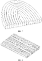
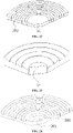
- the bendable strips can be stacked into Fresnel lens molds with a corresponding shape according to the designed Fresnel lens, for example, the elliptical Fresnel lens mold shown in FIG. 6 , the parabolic Fresnel lens mold shown in FIG. 7 , and the wavy Fresnel lens mold shown in FIG. 8 .
- Fresnel lens molds of any size can be fabricated by controlling the number of stacked bendable strips. Therefore, the preparation method of the Fresnel lens mold of the embodiment of the present application is not limited by the processing size of the ultra-precision machine tool, and Fresnel lens molds of various shapes and sizes can be produced according to requirements.
- the strip is a flexible, crimpable and high hardness material, which is made by grinding, polishing, etc.
- the strip in the embodiment of the present application is preferably a metal strip.
- milling, grinding or polishing is used to process one edge of the strip with the same optical structure as the lens structure on the corresponding annular strip of the Fresnel lens.
- the strips can be stacked and fixed by gluing, snapping, riveting, or expansion locking.
- one edge of the strip is processed so as to manufacture an optical structure with a corresponding cross-sectional shape.
- the cross-sectional shape of the optical structure can be triangle of any type, sector, circle, bow, parabola, ellipse, trapezoid or frustum composed of multiple line segments.
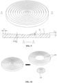
- the parameters of the designed Fresnel lens include the overall shape and size of the Fresnel lens, the cross-sectional shape of each annular strip lens structure of the Fresnel lens and the calculated cross-sectional shape parameters. Taking a circular Fresnel lens as an example, as shown in FIG.
- the A-A cross-sectional parameters include the distance between the tooth profiles of adjacent annular strip lens structures, namely the tooth pitch P, the tooth profile height H of each annular strip lens structure of Fresnel lens, the angle between the working surface B and the side perpendicular to the tooth profile of Fresnel lens, namely the draft angle ⁇ , and the angle between the working surface B and the side away from the tooth profile of Fresnel lens, which is the working angle ⁇ , and the interference surface C.
- the thickness of the bendable strip is selected to be the same as the tooth pitch P, that is, when the tooth pitch P and tooth height h of the designed Fresnel lens structure are both 0.15mm, a bendable strip with a thickness of 0.15mm is selected; according to the tooth height h of the Fresnel lens designed theoretically, the width of the bendable strip is selected to be ⁇ the tooth height h of the Fresnel lens.
- a suitable contact surface is required, preferably the width of the bendable strips > the tooth height h of the Fresnel lens.
- the thickness of the bendable strip is selected to be the same, the width of the strip can be selected to be greater than or equal to the maximum tooth pitch P of the lens structure of the annular strip, and the width of the annular strip can also be selected according to the corresponding tooth height.
- the width of the strip can be selected to be greater than or equal to the maximum tooth pitch P of the lens structure of the annular strip, and the width of the annular strip can also be selected according to the corresponding tooth height.
- a Fresnel lens mold including a reference unit and a stacked strip, the strip being bendable, and an optical structure is provided at one edge of the strip, which is the same as a lens structure of the designed Fresnel lens on the corresponding annular strip, a contour shape of the reference unit is the same as that of an annular strip of the corresponding area of the Fresnel lens.
- the strips are stacked on one contour surface of the reference unit according to the positions of the respective annular strips in the Fresnel lens and the orientation of the lens structures on the annular strips.
- the specific manufacturing method of the Fresnel lens mold is as follows:
- the raw material of the reference unit is preferably a material with higher hardness, so as to prolong the service life of the Fresnel lens mold.
- the raw materials are generally selected from metals, ceramics and polymer materials.
- the metal materials include but are not limited to stainless steel, aluminum alloys, aluminum-magnesium alloys and copper alloys; the ceramics include but are not limited to aluminum oxide ceramics; the polymer materials include but are not limited to carbon fiber reinforced plates and polytetrafluoroethylene.
- a cylinder with a certain size and positioned in the center is taken as the reference unit.
- this reference unit with a cylindrical surface with a certain shape is referred as the mold core 101.
- the contour shape of the processed mold core 101 is the same as the annular strip shape of the corresponding area of the designed Fresnel lens.
- the strip 300 formed as a whole, is continuously stacked on the contour surface of the mold core 101 according to the position of each annular strip in the Fresnel lens and the orientation of the lens structure on the annular strip so as to form a Fresnel lens mold; as shown in FIG. 13 , the strip 300 is formed with several sections, which are sequentially stacked on the contour surface of the mold core 101 according to the position of each annular strip in the Fresnel lens and the orientation of the lens structure on the annular strip so as to form a Fresnel lens mold.
- a cylinder with a certain size and positioned in the center, that is, the mold core 101 is taken as the reference unit.
- the contour shape of the processed mold core 101 is the same as the shape of the designed annular strip of the corresponding area of the Fresnel lens, and is provided with the same optical structure as the lens structure in the corresponding area of the Fresnel lens.
- the corresponding area parameters of the designed Fresnel lens as shown in FIG.
- the strip 300 formed as a whole, is continuously stacked on the contour surface of the mold core 101 according to the position of each annular strip in the Fresnel lens and the orientation of the lens structure on the annular strip so as to form a Fresnel lens mold.
- the strip 300 is formed into several sections, which are sequentially stacked on the contour surface of the mold core 101 according to the position of each annular strip in the Fresnel lens and the orientation of the lens structure on the annular strip so as to form a Fresnel lens mold.
- the contour shape of the processed mold core 101 is the same as the shape of the designed annular strip of the corresponding area of the Fresnel lens.
- the strip 300 is formed into several sections, which are sequentially stacked on the contour surface of the mold core 101 according to the position of each annular strip in the Fresnel lens and the orientation of the lens structure on the annular strip so as to form a Fresnel lens mold.
- the contour shape of the processed mold core 101 is the same as the shape of the designed annular strip of the corresponding area of the Fresnel lens, and is provided with the same optical structure as the lens structure in the corresponding area of the Fresnel lens. As shown in FIG. 19
- the strip 300 is formed into several sections, which are sequentially stacked on the contour surface of the mold core 101 according to the position of each annular strip in the Fresnel lens and the orientation of the lens structure on the annular strip so as to form a Fresnel lens mold.
- a part of a cylinder (less than half of the cylinder) with a certain size, which is positioned in the center and axially cut off, is taken as a reference unit, that is, the mold core 101, as shown in FIG. 21 , the contour shape of the processed mold core 101 is the same as the shape of the designed annular strip of the corresponding area of the Fresnel lens.
- the strip 300 is formed into several sections, which are sequentially stacked on the contour surface of the mold core 101 according to the position of each annular strip in the Fresnel lens and the orientation of the lens structure on the annular strip so as to form a Fresnel lens mold.
- a part of a cylinder (less than half of the cylinder) with a certain size, which is positioned in the center and axially cut off, is taken as a reference unit, that is, the mold core 101.
- the contour shape of the processed mold core 101 is the same as the shape of the designed annular strip of the corresponding area of the Fresnel lens, and is provided with the same optical structure as the lens structure in the corresponding area of the Fresnel lens. As shown in FIG.
- the strip 300 is formed into several sections, which are sequentially stacked on the contour surface of the mold core 101 according to the position of each annular strip in the Fresnel lens and the orientation of the lens structure on the annular strip so as to form a Fresnel lens mold.
- an elliptical cylinder with a certain size and positioned in the center is taken as the reference unit, that is, the mold core 101, as shown in FIG. 25 , the contour shape of the processed mold core 101 is the same as the shape of the designed annular strip of the corresponding area of the Fresnel lens.
- the strip 300, formed as a whole is continuously stacked on the contour surface of the mold core 101 according to the position of each annular strip in the Fresnel lens and the orientation of the lens structure on the annular strip so as to form a Fresnel lens mold. As shown in FIG.
- the strip 300 is formed into several sections, which are sequentially stacked on the contour surface of the mold core 101 according to the position of each annular strip in the Fresnel lens and the orientation of the lens structure on the annular strip so as to form a Fresnel lens mold.
- an elliptical cylinder with a certain size and positioned in the center is taken as the reference unit, that is, the mold core 101, as shown in FIG. 28 , the contour shape of the processed mold core 101 is the same as the shape of the designed annular strip of the corresponding area of the Fresnel lens, and is provided with the same optical structure as the lens structure in the corresponding area of the Fresnel lens. As shown in FIG.
- the strip 300 formed as a whole, is continuously stacked on the contour surface of the mold core 101 according to the position of each annular strip in the Fresnel lens and the orientation of the lens structure on the annular strip so as to form a Fresnel lens mold.
- the strip 300 is formed into several sections, which are sequentially stacked on the contour surface of the mold core 101 according to the position of each annular strip in the Fresnel lens and the orientation of the lens structure on the annular strip so as to form a Fresnel lens mold.
- a half of an elliptical cylinder with a certain size, which is positioned in the center and cut along the axial direction, is taken as a reference unit, that is, the mold core 101, as shown in FIG. 31 , the contour shape of the processed mold core 101 is the same as the shape of the designed annular strip of the corresponding area of the Fresnel lens.
- the strip 300 is formed into several sections, which are sequentially stacked on the contour surface of the mold core 101 according to the position of each annular strip in the Fresnel lens and the orientation of the lens structure on the annular strip so as to form a Fresnel lens mold.
- the contour shape of the processed mold core 101 is the same as the shape of the designed annular strip of the corresponding area of the Fresnel lens, and is provided with the same optical structure as the lens structure in the corresponding area of the Fresnel lens. As shown in FIG. 33
- the strip 300 is formed into several sections, which are sequentially stacked on the contour surface of the mold core 101 according to the position of each annular strip in the Fresnel lens and the orientation of the lens structure on the annular strip so as to form a Fresnel lens mold.
- the contour shape of the processed mold core 101 is the same as the shape of the designed annular strip of the corresponding area of the Fresnel lens.
- the strip 300 is formed into several sections, which are sequentially stacked on the contour surface of the mold core 101 according to the position of each annular strip in the Fresnel lens and the orientation of the lens structure on the annular strip so as to form a Fresnel lens mold.
- a parabola with a certain center size and positioned in the center is taken as the reference unit, that is, the mold core 101, as shown in FIG. 37
- the contour shape of the processed mold core 101 is the same as the shape of the designed annular strip of the corresponding area of the Fresnel lens, and is provided with the same optical structure as the lens structure in the corresponding area of the Fresnel lens. As shown in FIG.
- the strip 300 is formed into several sections, which are sequentially stacked on the contour surface of the mold core 101 according to the position of each annular strip in the Fresnel lens and the orientation of the lens structure on the annular strip so as to form a Fresnel lens mold.
- the strips are stacked on the surface of the mold core 101, and the size of the Fresnel lens mold is continuously increased by superposition, so that the size of the Fresnel lens mold will be not limited;
- the corresponding reference unit i.e., the mold core 101
- the designed reference unit i.e., the mold core 101
- the shape of the reference unit can be designed and processed according to any designed Fresnel lens parameters.
- a corresponding optical structure is arranged on the strip, and then a corresponding Fresnel lens mold and a partial Fresnel lens mold are formed by stacking.
- Fresnel lens molds and partial Fresnel lens molds of any size and concentric annular band can be manufactured without a limitation on shape and size, and the Fresnel lens mold manufactured by the manufacturing method has high structural accuracy and long service life.
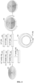
- the principle of shaft rotation is introduced in the process of stacking the strips, so that the whole process of making the Fresnel lens mold is more intelligent and automated.
- the mold core 101 is clamed on the mold core shaft 600, the strip 300 is wounded and clamped on the rotating shaft 500, and one end of the bendable strip 300 is fixed on the mold core shaft 600 with traction.
- said end of the strip 300 is pressed by a rubber pressing roller 700 , which is used to assist the lamination of the strip 300 and press the strip 300.
- the lamination direction of the bendable strip 300 should ensure that the orientation of the optical structure on the strip 300 is the same as the orientation of the lens structure on the mold core 101, so as to produce a Fresnel lens mold that meets the design requirements.
- the direction of the arrow represents the rotation direction of the rotating shaft 500 and the mold core shaft 600.
- Both the mold core shaft 600 and the rotating shaft 500 are rotatable under control, which can be manually rotated by manpower, or the rotating force can be provided by other power, such as a motor.
- the orientation of the mold core shaft 600 and the rotating shaft 500 can be horizontal or vertical, and it is only necessary to keep the mold core 101 and the wounded bendable strip 300 in the same plane.
- the mold core 101 is clamped on the mold core shaft 600, and the sectional strips 300 with optical structures are arranged in order according to the positions on the theoretically designed Fresnel lens.
- the end of the strip 300 is pressed with a rubber pressing roller 700 , which is used to assist the lamination of the strip 300 and press the strip 300; rotate the mold core shaft 600, stack the strip 300 on the outer contour of the mold core 101, fix the end of this section of strip, and stack the strips in sequence for fixing, so as to manufacture the Fresnel lens mold that meets the design requirements.
- the direction of the arrow represents the rotation direction of the mold core shaft 600; the mold core shaft 600 is rotatable under control, and can be manually rotated by manpower, or can be rotated by other power, such as a motor and the like.
- a Fresnel lens mold on the basis of the second embodiment, further including a fixing unit, the mold core is arranged on the fixing unit, and the specific manufacturing process is as follows:
- the fixing unit is a flat plate.
- the flat plate can be a metal flat plate or a non-metallic flat plate, preferably a flat plate with higher hardness.
- the flat plate is generally made of metal, ceramic and polymer materials.
- the metal materials include but are not limited to stainless steel, aluminum alloys, aluminum-magnesium alloys and copper alloys;
- the ceramics materials include but are not limited to aluminum oxide ceramics;
- the polymer materials include but are not limited to carbon fiber reinforced plates and polytetrafluoroethylene.
- the use of the flat plate facilitates of fixing to the mold core, which makes the fabrication of the Fresnel lens mold easier to operate.
- the mold core 101 is fixed on the flat plate 400, and the annular strip 300, formed as a whole, is continuously stacked on the contour surface of the mold core 101 according to the position of each annular strip in the Fresnel lens and the orientation of the lens structure on the annular strip so as to form a Fresnel lens mold.
- the mold core 101 is fixed on the flat plate 400, and the annular strip 300 is formed into several segments, which are sequentially stacked on the contour surface of the mold core 101 according to the position of each annular strip in the Fresnel lens and the orientation of the lens structure on the annular strip so as to form a Fresnel lens mold.
- the principle of shaft rotation is introduced in the process of stacking the strips, so that the whole process of making the Fresnel lens mold is more intelligent and automated.
- the mold core 101 is fixed on the flat plate 400, then the flat plate 400 fixed with the mold core 101 is clamped on the mold core shaft 600, the strip 300 is wounded and clamped on the rotating shaft 500, and one end of the bendable strip 300 is fixed on the mold core shaft 600 with traction.
- the end of the strip 300 is pressed with a rubber pressing roller 700, which is used to assist the lamination of the strip 300 and press the strip 300.
- the lamination direction of the bendable strip 300 should ensure that the orientation of the optical structure on the strip 300 is the same as the orientation of the lens structure on the mold core 101, so as to produce a Fresnel lens mold that meets the design requirements.
- the direction of the arrow represents the rotation direction of the rotating shaft 500 and the mold core shaft 600.
- Both the mold core shaft 600 and the rotating shaft 500 are rotatable under control, which can be manually rotated by manpower, or the rotating force can be provided by other power, such as a motor.
- the orientation of the mold core shaft 600 and the rotating shaft 500 can be horizontal or vertical, and it is only necessary to keep the mold core 101 and the wounded bendable strip 300 in the same plane.
- the mold core 101 is fixed on the flat plate 400, then the flat plate 400 fixed with the mold core 101 is clamped on the mold core 600, and the sectional strips 300 with optical structures are sequentially arranged according to the region parameters of Fresnel lenses designed in theory.
- the end of the strip 300 is pressed with a rubber pressing roller 700 , which is used to assist the lamination of the strip 300 and press the strip 300; rotate the mold core shaft 600, stack the strip 300 on the surface of the mold core 101, fix the end of this section of strip, and stack the strips in sequence for fixing, so as to manufacture the Fresnel lens mold that meets the design requirements.
- the direction of the arrow represents the rotation direction of the mold core shaft 600; the mold core shaft 600 is rotatable under control, and can be manually rotated by manpower, or can be rotated by other power, such as a motor and the like.
- a Fresnel lens mold including a reference unit and a stacked strip, the strip being bendable, and one edge of the strip is provided with an optical structure which is the same as a lens structure of the designed Fresnel lens on the corresponding annular strip, the strips are stacked on the inside of the reference unit according to the designed Fresnel lens parameters.
- the manufacturing process of the Fresnel lens mold is as follows:
- the strip 300 is formed into several segments, which are sequentially stacked on the inner side of the reference strip 102 according to the position of the annular strip in the designed Fresnel lens and the orientation of the lens structure on the annular strip so as to manufacture the corresponding Fresnel lens mold.
- the strip is formed as a whole and sequentially stacked on the inner side of the reference strip according to the position of the annular strip in the designed Fresnel lens and the orientation of the lens structure on the annular strip so as to manufacture the corresponding Fresnel lens mold.
- the Fresnel lens mold of the embodiment of the present application includes stacked strips, where the strip is bendable, and an optical structure is provided at one edge of the strip, which is the same as a lens structure of the designed Fresnel lens on the corresponding annular strip.
- the Fresnel lens mold will not be limited by the size of the processing lathe, and the strip is processed according to the designed Fresnel lens, thereby ensuring the processing accuracy of the Fresnel lens mold.
- the manufactured Fresnel lens mold can completely correspond to the designed Fresnel lens, and is not limited to a specific shape and size. Fresnel lens molds and partial Fresnel lens molds with any sizes and non-concentric rings can be manufactured.
- a method for manufacturing Fresnel lens in which the Fresnel lens molds manufactured in Embodiments 1-6 are made into Fresnel lenses by coating and transfer printing or hot-pressing or pressure injection molding.
- Coating and transfer printing is to evenly coat the optical glue on the base film or the Fresnel lens mold, so that the base film and the Fresnel lens mold are closely attached. Then radiation curing or heat curing, or reaction curing are applied to cure the optical glue to form a lens structure complementary to the optical structure on the Fresnel lens mold, and then separate the base film from the Fresnel lens mold. Because the adhesive property between the optical glue and the base film is stronger than the adhesive property of the Fresnel lens mold, the optical structure on the Fresnel lens mold is transfer printed to the base film to form an optical film with the designed Fresnel lens structure, and the designed Fresnel lens can be obtained by cutting. In the process of separating the base film from the Fresnel lens mold, a layer of release agent can be applied on the Fresnel lens mold in advance to facilitate the separation of the optical glue and the Fresnel lens mold.
- Hot-pressing is to heat the mold or heat and melt the base film, and after which, by applying pressure between the base film and the Fresnel lens mold, or applying pressure directly on the Fresnel lens mold, or applying vacuuming, a negative pressure can be formed on one side of the base film in order to achieve the pressurizing effect.
- the mold is cooled and molded, and the base film and the Fresnel lens mold are separated.
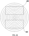
- the optical structure on the Fresnel lens mold is copied to the base film to form an optical film with a designed Fresnel lens structure, and the designed Fresnel lens can be obtained by cutting.
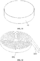
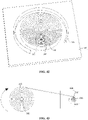
- the formed optical film with the designed Fresnel lens structure is shown in FIG. 46 .
- a required Fresnel lens optical film 800 is cut out from the base film on which the whole Fresnel lens is made so as to be manufactured as an important optical element of the projection screen or other display devices, which is made into a corresponding finished product for modulating the imaging display effect of the projection screen or other display devices.
- the optical film can also be used as the core component of solar concentrating and pumping laser weapons, and the corresponding products can be tailored according to the requirements.
- the process of manufacturing the Fresnel lens according to the embodiment of the present application is simple, and the obtained Fresnel lens has high precision.
- the manufacturing method can be used for manufacturing large-size Fresnel lens, and the obtained large-size Fresnel lens has no spliced seam, thus ensuring the performance of Fresnel lens, and can be used in situations with high requirements to the apparent quality of Fresnel lens such as electronic display, and further promote the development of downstream industries.
Landscapes
- Engineering & Computer Science (AREA)
- Mechanical Engineering (AREA)
- Manufacturing & Machinery (AREA)
- Health & Medical Sciences (AREA)
- Ophthalmology & Optometry (AREA)
- Moulds For Moulding Plastics Or The Like (AREA)
Applications Claiming Priority (2)
| Application Number | Priority Date | Filing Date | Title |
|---|---|---|---|
| CN202010283010.6A CN111169058B (zh) | 2020-04-13 | 2020-04-13 | 菲涅尔透镜模具及其制备方法和菲涅尔透镜的制备方法 |
| PCT/CN2020/128039 WO2021208412A1 (zh) | 2020-04-13 | 2020-11-11 | 菲涅尔透镜模具及其制备方法和菲涅尔透镜的制备方法 |
Publications (2)
| Publication Number | Publication Date |
|---|---|
| EP4137301A1 true EP4137301A1 (de) | 2023-02-22 |
| EP4137301A4 EP4137301A4 (de) | 2024-10-02 |
Family
ID=70645908
Family Applications (1)
| Application Number | Title | Priority Date | Filing Date |
|---|---|---|---|
| EP20930924.4A Pending EP4137301A4 (de) | 2020-04-13 | 2020-11-11 | Fresnel-linsenform und herstellungsverfahren dafür, und herstellungsverfahren für eine fresnel-linse |
Country Status (4)
| Country | Link |
|---|---|
| US (1) | US20230046945A1 (de) |
| EP (1) | EP4137301A4 (de) |
| CN (1) | CN111169058B (de) |
| WO (1) | WO2021208412A1 (de) |
Families Citing this family (5)
| Publication number | Priority date | Publication date | Assignee | Title |
|---|---|---|---|---|
| CN111169058B (zh) * | 2020-04-13 | 2020-07-03 | 成都菲斯特科技有限公司 | 菲涅尔透镜模具及其制备方法和菲涅尔透镜的制备方法 |
| CN113406737A (zh) * | 2021-07-09 | 2021-09-17 | 付泽宇 | 联合菲涅尔透镜和眼睛佩戴物 |
| US20240052111A1 (en) * | 2022-08-15 | 2024-02-15 | The Regents Of The University Of California | Self-assembled concentric nanoparticle rings to generate orbital angular momentum |
| CN115542436B (zh) * | 2022-10-13 | 2025-11-18 | 浙江水晶光电科技股份有限公司 | 一种菲涅尔透镜及其制备方法 |
| CN117644429A (zh) * | 2023-04-18 | 2024-03-05 | 伯恩创盛技术研发(惠州)有限公司 | 菲涅尔透镜纹理模具的加工方法 |
Family Cites Families (25)
| Publication number | Priority date | Publication date | Assignee | Title |
|---|---|---|---|---|
| DE10038213A1 (de) * | 2000-08-04 | 2002-03-07 | Osram Opto Semiconductors Gmbh | Strahlungsquelle und Verfahren zur Herstellung einer Linsensform |
| US20040099971A1 (en) * | 2002-11-25 | 2004-05-27 | Technology Resource International Corporation | Lens molds and method of using the same |
| JP4212902B2 (ja) * | 2003-01-07 | 2009-01-21 | 大日本印刷株式会社 | フレネルレンズ、フレネルレンズ成形型、フレネルレンズ製造方法及びフレネルレンズを用いた透過型スクリーン |
| JP2006289871A (ja) * | 2005-04-13 | 2006-10-26 | Fuji Photo Film Co Ltd | 輪帯光学素子の製造方法および輪帯光学素子用金型の製造方法 |
| WO2008123559A1 (en) * | 2007-03-30 | 2008-10-16 | Fujifilm Corporation | Method and apparatus for manufacturing uneven thickness resin sheet |
| JP2010066518A (ja) * | 2008-09-11 | 2010-03-25 | Glory Science Co Ltd | フレネルレンズ、フレネルレンズ製造装置及び方法 |
| CN101750701B (zh) * | 2008-12-18 | 2012-10-10 | 鸿富锦精密工业(深圳)有限公司 | 镜头模组 |
| TW201043428A (en) * | 2009-06-05 | 2010-12-16 | Hon Hai Prec Ind Co Ltd | Mold and method for manufacturing Fresnel lens used the same |
| CN102085723A (zh) * | 2009-12-04 | 2011-06-08 | 鸿富锦精密工业(深圳)有限公司 | 成型透镜的模具 |
| CN102103241B (zh) * | 2009-12-18 | 2013-11-06 | 鸿富锦精密工业(深圳)有限公司 | 镜头模组及其组装方法 |
| US9395470B2 (en) * | 2012-04-05 | 2016-07-19 | Canon Kabushiki Kaisha | Molded-article manufacturing method, mold, and optical element including fresnel lens |
| CN103149609B (zh) * | 2013-03-13 | 2015-03-18 | 毛建华 | 超大口径菲涅尔透镜加工方法 |
| WO2014139017A1 (en) * | 2013-03-14 | 2014-09-18 | Dbm Reflex Enterprises Inc. | Injection molding apparatus for structured optical parts |
| JP6413651B2 (ja) * | 2013-12-04 | 2018-10-31 | 大同特殊鋼株式会社 | フレネルレンズおよびフレネルレンズの製造方法 |
| CN103895219B (zh) | 2014-04-25 | 2016-01-20 | 成都菲斯特科技有限公司 | 用于制作菲涅尔透镜的锥形辊筒 |
| CN110226110B (zh) * | 2016-09-13 | 2021-12-21 | 脸谱科技有限责任公司 | 具有用于减少光学伪影的动态拔模的菲涅耳透镜 |
| JP7169052B2 (ja) * | 2017-07-11 | 2022-11-10 | 株式会社ダイセル | フレネルレンズ、及びその製造方法 |
| JP2019025787A (ja) * | 2017-07-31 | 2019-02-21 | 株式会社クラレ | 光学部材シートの製造方法および成形型 |
| TWI657257B (zh) * | 2017-08-28 | 2019-04-21 | 大立光電股份有限公司 | 塑膠透鏡、塑膠環形光學元件、鏡頭模組及電子裝置 |
| US10473827B1 (en) * | 2017-11-17 | 2019-11-12 | Facebook Technologies, Llc | Fresnel lens with textured draft surfaces |
| CN108890944B (zh) * | 2018-08-02 | 2020-08-18 | 山东宇影光学仪器有限公司 | 一种用于制造菲涅尔透镜的模具及其生产方法 |
| CN209198832U (zh) * | 2018-11-09 | 2019-08-02 | 宁波舜宇光电信息有限公司 | 透镜模块以及摄像模组 |
| CN209851398U (zh) * | 2019-04-10 | 2019-12-27 | 成都贝瑞光电科技股份有限公司 | 一种便于拆装的透镜模具 |
| CN110238996A (zh) * | 2019-05-29 | 2019-09-17 | 广东省医疗器械研究所 | 一种微针阵列模具的制备方法 |
| CN111169058B (zh) * | 2020-04-13 | 2020-07-03 | 成都菲斯特科技有限公司 | 菲涅尔透镜模具及其制备方法和菲涅尔透镜的制备方法 |
-
2020
- 2020-04-13 CN CN202010283010.6A patent/CN111169058B/zh active Active
- 2020-11-11 US US17/792,740 patent/US20230046945A1/en active Pending
- 2020-11-11 WO PCT/CN2020/128039 patent/WO2021208412A1/zh not_active Ceased
- 2020-11-11 EP EP20930924.4A patent/EP4137301A4/de active Pending
Also Published As
| Publication number | Publication date |
|---|---|
| WO2021208412A1 (zh) | 2021-10-21 |
| US20230046945A1 (en) | 2023-02-16 |
| CN111169058B (zh) | 2020-07-03 |
| CN111169058A (zh) | 2020-05-19 |
| EP4137301A4 (de) | 2024-10-02 |
Similar Documents
| Publication | Publication Date | Title |
|---|---|---|
| EP4137301A1 (de) | Fresnel-linsenform und herstellungsverfahren dafür, und herstellungsverfahren für eine fresnel-linse | |
| CN1297826C (zh) | 带微型透镜阵列的光学零件的制造方法 | |
| CN1064589C (zh) | 光学元件集合体的连续形成方法及其装置 | |
| JPH0222013A (ja) | 押形工具製作用マスターの製造方法 | |
| KR100316121B1 (ko) | 그라인딩 휠 | |
| CN112549378B (zh) | 一种复合材料波纹夹层筒体的一体化成型模具及其方法 | |
| CN105652485B (zh) | 卷对卷制备液晶柱透镜光栅膜的方法 | |
| EP2013652B1 (de) | Farbrad | |
| CN102380831A (zh) | 一种金刚石滚轮制作过程中的上砂方法 | |
| CN110568576A (zh) | 一种透镜柔性支撑装置 | |
| JP5518800B2 (ja) | 電鋳ロール及びその製造方法 | |
| CN112483521A (zh) | 刚性热防护层套接于非封闭等径回转体舱段的工装及方法 | |
| JP2010276845A (ja) | フレネルレンズシート、その製造方法およびそれに用いるスタンパの製造方法並びにフレネルレンズシートを含む太陽光発電装置 | |
| CN112123825B (zh) | 一种透镜加工设备及其加工方法 | |
| CN211251050U (zh) | 一种全氟离子膜钢带流延机的流延刀 | |
| CN105372734B (zh) | 微棱镜反光材料制作方法 | |
| CN110814147B (zh) | 一种设有随形组合式线圈的大尺寸板料成型装置及方法 | |
| CN215882140U (zh) | 一种主辊及切割设备 | |
| KR20210025153A (ko) | 탄소섬유강화 플라스틱 기반 나노 원통 금형 제조 방법 | |
| JPS6115806B2 (de) | ||
| CN102581783B (zh) | 一种易回收的电镀金刚石砂轮的制造方法 | |
| CN114523583A (zh) | 一种主辊及切割设备 | |
| CN113580452A (zh) | 一种光学透镜辊筒模具及其制造方法 | |
| US20140300011A1 (en) | Apparatus and method for manufacturing optical film | |
| SU1100112A1 (ru) | Оправка дл изготовлени деталей из композиционного материала методом намотки |
Legal Events
| Date | Code | Title | Description |
|---|---|---|---|
| STAA | Information on the status of an ep patent application or granted ep patent |
Free format text: STATUS: THE INTERNATIONAL PUBLICATION HAS BEEN MADE |
|
| PUAI | Public reference made under article 153(3) epc to a published international application that has entered the european phase |
Free format text: ORIGINAL CODE: 0009012 |
|
| STAA | Information on the status of an ep patent application or granted ep patent |
Free format text: STATUS: REQUEST FOR EXAMINATION WAS MADE |
|
| 17P | Request for examination filed |
Effective date: 20220714 |
|
| AK | Designated contracting states |
Kind code of ref document: A1 Designated state(s): AL AT BE BG CH CY CZ DE DK EE ES FI FR GB GR HR HU IE IS IT LI LT LU LV MC MK MT NL NO PL PT RO RS SE SI SK SM TR |
|
| DAV | Request for validation of the european patent (deleted) | ||
| DAX | Request for extension of the european patent (deleted) | ||
| A4 | Supplementary search report drawn up and despatched |
Effective date: 20240902 |
|
| RIC1 | Information provided on ipc code assigned before grant |
Ipc: B29C 33/30 20060101ALI20240827BHEP Ipc: B29C 33/42 20060101ALI20240827BHEP Ipc: B29C 33/38 20060101ALI20240827BHEP Ipc: B29D 11/00 20060101AFI20240827BHEP |