EP4135954B1 - Rasierklingeneinheit - Google Patents
Rasierklingeneinheit Download PDFInfo
- Publication number
- EP4135954B1 EP4135954B1 EP21724421.9A EP21724421A EP4135954B1 EP 4135954 B1 EP4135954 B1 EP 4135954B1 EP 21724421 A EP21724421 A EP 21724421A EP 4135954 B1 EP4135954 B1 EP 4135954B1
- Authority
- EP
- European Patent Office
- Prior art keywords
- blade
- facet
- razor
- section
- shoulder
- Prior art date
- Legal status (The legal status is an assumption and is not a legal conclusion. Google has not performed a legal analysis and makes no representation as to the accuracy of the status listed.)
- Active
Links
Images

Classifications
-
- B—PERFORMING OPERATIONS; TRANSPORTING
- B26—HAND CUTTING TOOLS; CUTTING; SEVERING
- B26B—HAND-HELD CUTTING TOOLS NOT OTHERWISE PROVIDED FOR
- B26B21/00—Razors of the open or knife type; Safety razors or other shaving implements of the planing type; Hair-trimming devices involving a razor-blade; Equipment therefor
- B26B21/54—Razor-blades
- B26B21/58—Razor-blades characterised by the material
- B26B21/60—Razor-blades characterised by the material by the coating material
-
- B—PERFORMING OPERATIONS; TRANSPORTING
- B26—HAND CUTTING TOOLS; CUTTING; SEVERING
- B26B—HAND-HELD CUTTING TOOLS NOT OTHERWISE PROVIDED FOR
- B26B21/00—Razors of the open or knife type; Safety razors or other shaving implements of the planing type; Hair-trimming devices involving a razor-blade; Equipment therefor
- B26B21/54—Razor-blades
- B26B21/56—Razor-blades characterised by the shape
-
- B—PERFORMING OPERATIONS; TRANSPORTING
- B26—HAND CUTTING TOOLS; CUTTING; SEVERING
- B26B—HAND-HELD CUTTING TOOLS NOT OTHERWISE PROVIDED FOR
- B26B21/00—Razors of the open or knife type; Safety razors or other shaving implements of the planing type; Hair-trimming devices involving a razor-blade; Equipment therefor
- B26B21/40—Details or accessories
- B26B21/4012—Housing details, e.g. for cartridges
- B26B21/4018—Guard elements
-
- B—PERFORMING OPERATIONS; TRANSPORTING
- B26—HAND CUTTING TOOLS; CUTTING; SEVERING
- B26B—HAND-HELD CUTTING TOOLS NOT OTHERWISE PROVIDED FOR
- B26B21/00—Razors of the open or knife type; Safety razors or other shaving implements of the planing type; Hair-trimming devices involving a razor-blade; Equipment therefor
- B26B21/40—Details or accessories
- B26B21/4012—Housing details, e.g. for cartridges
- B26B21/4025—Cap elements
-
- B—PERFORMING OPERATIONS; TRANSPORTING
- B26—HAND CUTTING TOOLS; CUTTING; SEVERING
- B26B—HAND-HELD CUTTING TOOLS NOT OTHERWISE PROVIDED FOR
- B26B21/00—Razors of the open or knife type; Safety razors or other shaving implements of the planing type; Hair-trimming devices involving a razor-blade; Equipment therefor
- B26B21/40—Details or accessories
- B26B21/4012—Housing details, e.g. for cartridges
- B26B21/4031—Housing details, e.g. for cartridges characterised by special geometric shaving parameters, e.g. blade span or exposure
-
- B—PERFORMING OPERATIONS; TRANSPORTING
- B26—HAND CUTTING TOOLS; CUTTING; SEVERING
- B26B—HAND-HELD CUTTING TOOLS NOT OTHERWISE PROVIDED FOR
- B26B21/00—Razors of the open or knife type; Safety razors or other shaving implements of the planing type; Hair-trimming devices involving a razor-blade; Equipment therefor
- B26B21/08—Razors of the open or knife type; Safety razors or other shaving implements of the planing type; Hair-trimming devices involving a razor-blade; Equipment therefor involving changeable blades
- B26B21/14—Safety razors with one or more blades arranged transversely to the handle
- B26B21/22—Safety razors with one or more blades arranged transversely to the handle involving several blades to be used simultaneously
- B26B21/222—Safety razors with one or more blades arranged transversely to the handle involving several blades to be used simultaneously with the blades moulded into, or attached to, a changeable unit
- B26B21/225—Safety razors with one or more blades arranged transversely to the handle involving several blades to be used simultaneously with the blades moulded into, or attached to, a changeable unit the changeable unit being resiliently mounted on the handle
Definitions
- the invention generally relates to razor blade cartridges and more particularly to razor blade cartridges having razor blades with a skin contacting shoulder.
- Razor cartridges typically comprise a cartridge housing including cap and guard structures and one or more razor blade assemblies located between the cap and guard structures.
- a plane may extend between the upper surfaces of the cap and guard structures to define a shaving plane.
- the razor blade assemblies typically comprise razor blades having a symmetrical shape. It is well known that the shaving geometry of a razor cartridge is important in determining the shaving performance of the cartridge.
- the shaving geometry defines the position and orientation of the blades in relation to other skin contacting parts, in particular, the cap structure and guard structure of the razor cartridge.
- One parameter of the shaving geometry is blade exposure, which is the perpendicular distance by which the cutting edge of a blade protrudes above or below the shaving plane. While current razor blades perform adequately, in order for next generation products to perform better, improvements in shaving geometry such as blade shape can be made.
- US2005028389 discusses a razor blade comprised of a layer of CVD diamond having a monolithic elongate cutting edge, which may be asymmetric.
- US2244053 discusses a sintering process for producing symmetric razor edges.
- a razor cartridge comprising: a housing and a blade assembly mounted to the housing.
- the blade assembly may comprise at least one razor blade defined by a substrate comprising a first portion and a second portion.
- the first portion may comprise first and second outer surfaces.
- the second portion may comprise first and second sections separated by a split line.
- the first section may comprise a first facet and an end facet.
- the second section may comprise an end facet.
- the end facets of the first and second sections may converge at a tip to define a cutting edge.
- a shoulder may be positioned between the first facet and the end facet of the first section and define a skin-contacting surface.
- the end facet of the second section may comprise a second facet and the end facet of the first section may comprise a third facet.
- the second section may further comprise a second facet extending from the second outer surface of the first portion.
- the end facet of the second section may comprise a fourth facet and the end facet of the first section may comprise a third facet.
- the end facet of the second section may be located closer to the split line than the first facet and the end facet of the first section.
- the first and second outer surfaces of the first portion of the substrate may be generally parallel to one another and the split line may pass through the tip and may be generally parallel to the first and second outer surfaces of the first portion.
- the first and second sections of the second portion may define asymmetric first and second sections.
- the first facet may extend directly from the first outer surface of the first portion.
- the housing may comprise a cap structure and a guard structure.
- a shaving plane may be defined between the cap structure and the guard structure.
- the blade assembly may further comprise a blade support member to which the razor blade substrate is coupled.
- the blade support member may be configured such that the shoulder positioned between the first facet and the end facet of the first section is positioned in or near the shaving plane.
- the shoulder may be positioned near the shaving plane when the shoulder is located above or below the shaving plane by a distance less than about 0.2 mm and less than about 0.5 mm, respectively, from the shaving plane.
- the cartridge may further comprise first and second clips mounted to the housing and engaging opposing ends of the shoulder of the substrate defining the razor blade to secure the razor blade within the housing.
- a razor cartridge comprising a housing; a first blade assembly mounted to the housing, the first blade assembly comprising a first razor blade; and a second blade assembly mounted to the housing, the second blade assembly comprising a second razor blade.
- At least one of the first razor blade or the second razor blade may be defined by a substrate comprising a first portion comprising first and second outer surfaces and a second portion comprising first and second sections separated by a split line.
- the first section may comprise a first facet and an end facet.
- the second section may comprise an end facet.
- the end facets of the first and second sections may converge at a tip to define a cutting edge.
- a shoulder may be positioned between the first facet and the end facet of the first section and defines a skin-contacting surface.
- the end facet of the second section may comprise a second facet and the end facet of the first section may comprise a third facet.
- the second section may further comprise a second facet extending from the second outer surface of the first portion.
- the end facet of the second section may comprise a fourth facet and the end facet of the first section may comprise a third facet.
- the end facet of the second section may be located closer to the split line than the first facet and the end facet of the first section.
- the first and second outer surfaces of the first portion of the substrate may be generally parallel to one another and the split line may pass through the tip and may be generally parallel to the first and second outer surfaces of the first portion.
- the first and second sections of the second portion may define asymmetric first and second sections.
- the first facet may extend directly from the first outer surface of the first portion.
- the housing may further comprise a cap structure and a guard structure.
- a shaving plane may be defined between the cap structure and the guard structure.
- the first blade assembly may further comprise a blade support member to which the first razor blade is coupled.
- the blade support member may be configured such that the shoulder of the substrate defining the first razor blade is positioned in or near the shaving plane.
- the shoulder may be positioned near the shaving plane when the shoulder is located above or below the shaving plane by a distance less than about 0.2 mm and less than about 0.5 mm, respectively, from the shaving plane.
- the cartridge may further comprise first and second clips mounted to the housing and engaging opposing ends of the shoulder of the substrate defining the first razor blade to secure the first razor blade in the housing.
- a shaving plane may be defined for the first razor blade by a plane extending from an uppermost surface portion of a skin contacting element in front of and behind the cutting edge of the first razor blade.
- the first blade assembly may further comprise a blade support member to which the first razor blade is coupled.
- the blade support member may be configured such that the shoulder of the first razor blade is positioned in or near the shaving plane.
- asymmetric blade means a blade defined by a substrate having a first portion comprising a blade body and a second portion comprising a tip portion wherein a split line passes through a tip of the tip portion, extends through the first and second portions and separates the second portion into generally asymmetric first and second sections.
- the outer surface of the first section of the second portion is asymmetric with regards to the outer surface of the second section.
- the outer surface of the first section of the second portion may function as a skin-contacting surface, and the outer surface of the second section of the second portion may function as a hair-cutting surface.
- a “bevel shoulder,” “bevel shoulder structure,” or “shoulder” which can be used interchangeably, are used herein to signify the structure on the outer surface of the first section of the second portion of the substrate of the razor blade.
- the bevel shoulder structure is disposed where facets meet in the first section, and the bevel shoulder defines a significant portion of the skin-contacting surface of the blade.
- the bevel shoulder can be smooth, rounded, or angled and is generally a linear structure running parallel to a cutting edge.
- the bevel shoulder structure of the present invention performs the bulk of the skin-contacting function of the blade and, hence, takes pressure off the tip. In providing minimal to no tip pressure, the shoulder provides a highly defined skin-guarding benefit built into the first section.
- a “split line,” as used herein, means a line extending through the tip of the tip portion of the blade substrate, separates the second portion into asymmetrical first and second sections and is generally parallel with first and second generally parallel outer surfaces of the first portion defining the blade body of the blade substrate.
- a “shaving plane,” as used herein, means a plane extending between upper surfaces of a cap structure of a razor cartridge housing and a guard structure of the razor cartridge housing.
- the “shaving plane” can be a plane tangent to each of the cap structure and guard structure. In some embodiments, not all of the cap structure, guard structure and uppermost surface portions of the razor blades in a razor cartridge will be located within a same plane.
- “shaving plane,” as used herein, is intended to mean a plane extending between the uppermost surface portions of two skin contacting elements, one immediately in front of and one immediately behind the razor blade tip of the razor blade.
- the shaving plane is defined by a plane extending from an upper surface, i.e., uppermost surface portion, of the guard structure on a first side of the first razor blade tip and an uppermost surface portion of a skin contacting element directly adjacent to and on a second side of the first blade tip.
- the shaving plane is defined by a plane extending from the uppermost surface portions of adjacent skin contacting elements on either side of the intermediate razor blade tip.
- the uppermost surface portion on a razor blade may be defined by the bevel shoulder
- the uppermost surface portion of the skin contacting element immediately behind the razor blade tip of the razor blade may comprise the razor blade's bevel shoulder.
- An uppermost surface portion on a skin contacting element on either side of a razor blade tip can be an uppermost surface on an adjacent razor blade, an element on the razor blade itself (such as a bevel shoulder), or a guard structure.
- the shaving plane is defined by a plane extending from the uppermost surface portion of razor blade 18B, the blade directly in front of the blade 18A, and the bevel shoulder (41, 81) of the razor blade 18A.
- the uppermost surface portion of razor blade 18B as shown is a bevel shoulder as well (e.g., 41, 81).
- a first blade in a sequence of blades such as razor blade 18E in FIG.
- the shaving plane is defined by a plane extending from the uppermost surface portion of a preceding guard structure 28 and the uppermost surface portion immediately behind the razor blade tip of the razor blade which in this instance may be the blade bevel shoulder (e.g., 41, 81) of razor blade 18E.
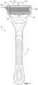
- a shaving razor system 10 comprises a handle 12 and a razor cartridge 14.
- the razor cartridge 14 may be detachably mounted to the handle 12 with a connector 20 as shown, and in other examples, the razor cartridge 14 may be attached permanently to the handle 12.
- the razor cartridge 14 may pivot relative to the handle 12.
- the razor cartridge 14 may include a cartridge housing 16 having one or more blades 18. Although five blades are shown in Fig. 1 , it is understood that any number of blades, more or less, may be mounted within the razor cartridge 14.
- the blades 18 may be mounted within the cartridge housing 16 and secured with clips 24a and 24b as shown.
- the cartridge housing 16 may further comprise a cap structure 22 located near a back of the cartridge housing 16 and one or more guard structures 28 located near a front of the cartridge housing 16.
- the cap structure 22 may comprise one or more lubrication members (not labeled).
- the substrate 30 may be coated. Coatings on the substrate 30 may be in the range of 200 to 1500 angstroms, preferably between 300 and 1000 angstroms.
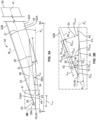
- Fig. 3A is a cross-sectional side view of an asymmetrical razor blade 18 in accordance with a first embodiment of the present disclosure.
- the razor blade 18 is defined by a substrate 30 comprising a first portion 32 comprising a blade body 132A and a second portion 34 comprising a tip portion 134A.
- dotted line 33 extends between the first and second portions 32 and 34.
- the razor blade 18 may be formed from stainless steel, other metals and/or alloys, plastic, or any other material or combinations thereof.
- the first portion 32 may comprise first and second generally parallel outer surfaces 32A and 32B and may be defined by the portion of the substrate 30 where there are no facets.
- the second portion 34 may comprise generally asymmetric first and second sections 36 and 38, respectively, separated by a split line SL 34 , wherein the first and second sections 36 and 38 comprise third and fourth asymmetric outer surfaces 36A and 38A.
- the split line SL 34 may pass through or emanate from a tip 46 of the tip portion 134A and may be generally parallel with the first and second outer surfaces 32A and 32B of the first portion 32 of the blade substrate 30, see Fig. 3A .
- the split line SL 34 may extend through the first portion 32. In the example embodiment of Figs. 3A and 3B , the split line SL 34 does not separate the first and second portions 32 and 34 into equal halves.
- the asymmetrical first and second sections 36 and 38 of the second portion 34 may extend longitudinally away from the tip 46 different distances.
- the first section 36 comprises first and third bevels or facets 40 and 44 and the second section 38 comprises a second bevel or facet 42.
- the first facet 40 may extend directly from the first outer surface 32A and may be positioned between the first outer surface 32A and the third facet 44.
- the third facet 44 may extend directly from the first facet 40.
- a bevel shoulder 41 may be defined where the first and third facets 40 and 44 meet.
- the bevel shoulder 41 is a structure that is generally linear (e.g., extending into the page and along the X direction) running parallel to a cutting edge 19 of the blade 18 as shown for instance in Fig. 3D .
- the bevel shoulder 41 may be smooth, rounded, or angled.
- the second facet 42 may extend directly from the second outer surface 32B.
- the second and third facets 42 and 44 may define end facets that converge at the tip 46 to define the cutting edge 19 of the blade 18, which performs the cutting of hair.
- the bevel shoulder 41 between the first and third facets 40 and 44 may contact and move along the skin of a user.
- An angle ⁇ ' of the bevel shoulder 41, see Fig. 3A extending from the first facet 40 to the third facet 44 may be from 162 degrees to 176 degrees.
- a length L 40 of the first facet 40 may be greater than a length L 42 and L 44 of each of the second and third facets 42 and 44, see Figs. 3A and 3B .
- the length L 44 of the third facet 44 may be less than the length of the second facet 42.
- the length L 40 of the first facet 40 may be from 100 microns to 500 microns
- the length L 42 of the second facet 42 may be from 8 microns to 200 microns
- the length L 44 of the third facet 44 may be from 8 microns to 150 microns, preferably from 8 microns to 50 microns.
- the first facet 40 may extend inwardly from the first outer surface 32A toward the second outer surface 32B and the second facet 42 may extend inwardly from the second outer surface 32B toward the first outer surface 32A, see Fig. 3A .
- a plane P 1 extending through a center of the first portion 32 parallel to the first and second outer surfaces 32A and 32B may extend through the first facet 40, see Fig. 3A .
- the plane P 1 bisects the first portion 32 into equal halves.
- a first angle ⁇ 1 between the first facet 40 and a first line extending from the first outer surface 32A of the first portion 32 may be greater than a second angle ⁇ 2' between the second facet 42 and a second line extending from the second outer surface 32B of the first portion 32, see Figs. 3A and 3B .
- a third angle ⁇ 1' between the third facet 44 and a third line extending from the first facet 40 may be greater than the second angle ⁇ 2' between the second facet 42 and the second line extending from the second outer surface 32B of the first portion 32.
- a wedge angle ⁇ ' may extend between the second and third facets 42 and 44, see Fig. 3B .
- a value of the wedge angle ⁇ ' may be equal to the sum of a value of the first angle ⁇ 1' , a value of the second angle ⁇ 2' and a value of the third angle ⁇ 1' and may fall within a range of from 13.5 degrees to 30 degrees.
- a smaller wedge angle ⁇ ' is advantageous as it may result in a sharper cutting edge of the blade 18.
- the first angle ⁇ 1' may fall within a range of from 8 degrees to 21 degrees; the second angle ⁇ 2' may fall within a range from 1 degree to 12 degrees, preferably from 2 degrees to 8 degrees; and the third angle ⁇ 1' may fall within a range from 4 degrees to 18 degrees, preferably from 8 to 18 degrees.
- the sum of the first angle ⁇ 1 and the third angle ⁇ 1' is greater than or equal to a blade tangent angle ⁇ , discussed below.
- the split line SL 34 separating the generally asymmetric first and second sections 36 and 38 of the second portion 34 of the razor blade 18 passes through the tip 46 and is generally parallel with the first and second outer surfaces 32A and 32B of the first portion 32, see Fig. 3A .
- a substantial portion of the second facet 42 may be located closer to the split line SL 34 than a substantial portion of each of the first and third facets 40 and 44, see Figs. 3A and 3B .
- a sum of a first distance D SL2A perpendicular to the split line SL 34 and extending from the split line SL 34 to the first or the third facet 40, 44 and a second distance D SL2B perpendicular to the split line SL 34 and extending from the split line SL 34 to the second facet 42 or the second outer surface 32B of the first portion 32 may be between 1.9 microns to 4.6 microns.
- a sum of a first distance D SL3A perpendicular to the split line SL 34 and extending from the split line SL 34 to the first or the third facet 40, 44 and a second distance D SL3B perpendicular to the split line SL 34 and extending from the split line SL 34 to the second facet 42 or the second outer surface 32B of the first portion 32 may be between 3.8 microns to 9.2 microns.
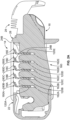
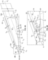
- Fig. 2A illustrates a cross-sectional view of the razor cartridge 14.
- the razor cartridge 14 further comprises first, second, third, fourth and fifth razor blade assemblies 180A-180E comprising first, second, third, fourth and fifth razor blades 18A-18E, wherein each of the razor blades 18A-18E is formed to correspond to the razor blade 18 illustrated in Figs. 3A and 3B .
- the first blade assembly 180A may comprise the first blade 18A and a first blade support member or blade carrier 120A coupled to the first blade 18A.
- the second blade assembly 180B may comprise the second blade 18B and a second blade support member or blade carrier 120B coupled to the second blade 18B.
- the third blade assembly 180C may comprise the third blade 18C and a third blade support member or blade carrier 120C coupled to the third blade 18C.
- the fourth blade assembly 180D may comprise the fourth blade 18D and a fourth blade support member or blade carrier 120D coupled to the fourth blade 18D.
- the fifth blade assembly 180E may comprise the fifth blade 18E and a fifth blade support member or blade carrier 120E coupled to the fifth blade 18E.
- the blade support members 120A-120E may comprise, for example, stainless steel.
- the blade support members 120A-120E may be integral with their corresponding blades 18A-18E, or alternatively, the blades 18A-18E may be fixedly coupled to the respective blade support members 120A-120E, such as by welding, adhesive, or other suitable technique.
- Each blade assembly 180A-180E may be mounted within the cartridge housing 16 of the razor cartridge 14.
- the blade support members 120A-120E may be positioned within a respective blade slot 162A-162E extending in the cartridge housing 16, in an X direction, of the housing 16, see Fig. 1 , and may be fixed or floating.
- the blade support members 120A-120E may be resiliently mounted within the housing and may be biased to their raised, at-rest positions (that is, not loaded by shaving forces) via polymeric leaf-spring arms (not shown), one example of which is disclosed in U.S. Patent No. 10,391,652 .
- the blade assemblies 180A-180E may be secured by clips 24B (only one of which is illustrated in Fig. 2A ) or other known assembly methods.
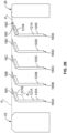
- Fig. 2B schematically illustrates the cap structure 22, the guard structure 28 and the first, second, third, fourth and fifth razor blade assemblies 180A-180E of the razor cartridge 14 of Fig. 2A .
- a plane extending between the upper surfaces of the cap structure 22 and the guard structure 28 of the cartridge housing 16 of the razor cartridge 14 may define a shaving plane Ps, i.e., a plane tangent to each of the cap structure and guard structure 22 and 28.
- the "shaving plane" for a given razor blade within such a razor cartridge may be defined as a plane extending between skin contacting elements immediately in front of and behind a razor blade tip of the given razor blade.
- the uppermost portion of blade 18E' is located slightly below the locations of the blade 18E shown in solid line as well as the upper surface of the guard structure 28.
- the shaving plane P S' for the modified blade 18E' extends from the upper surface of the guard structure 28' to the uppermost portion of a skin contacting element behind the tip of the blade 18E, which comprises the bevel shoulder of the blade 18E'.
- the shaving geometry of a razor cartridge is important in determining the shaving performance of the cartridge.
- the shaving geometry defines the position and orientation of the blades in relation to other skin contacting parts, in particular, the cap structure and guard structure of the razor cartridge.
- One parameter of the shaving geometry is blade exposure, which is the perpendicular distance by which the cutting edge of a blade protrudes above or below the shaving plane.
- the first, second, third, fourth and fifth blade support members 120A-120E may be configured to position their respective blades 18A-18E such that the bevel shoulder 41 of the substrate 30 defining each blade 18A-18E is positioned in or near the shaving plane P S , see also Figs. 3A-3C .
- each of the blade support members 120A-120E may comprise a lower portion 121A and an upper portion 121B, which extends at an angle of ⁇ 121 of from 100 degrees to 125 degrees to the lower portion 121A, see Fig. 2B .
- the upper portion 121B of each blade support member 120A-120E may be coupled to the outer surface 32B of the first portion 32 of the substrate 30 defining the corresponding blades 18A-18E. Due to the asymmetric shape of the substrate 30 and the angle ⁇ 121 between the lower and upper portions 121A and 121B of each blade support member, the bevel shoulder 41 of the substrate 30 defining each blade 18A-18E is positioned in or near the shaving plane P S , see also Figs. 3A-3C .
- the bevel shoulder 41 is considered to be positioned in or near the shaving plane P S when a portion of the bevel shoulder 41, which shoulder 41 extends in the X direction, see Figs. 1 and 3A , lies within the shaving plane P S , i.e., the shaving plane P S is tangent to the portion of the bevel shoulder 41, or a portion of the bevel shoulder 41 is located slightly above the shaving plane P S by a distance D 1 less than about 0.2 mm from the shaving plane Ps or slightly below the shaving plane P S by a distance D 2 of less than about 0.5 mm from the shaving plane Ps, see Fig. 3C .
- the cutting edge 19 of the blade 18 may be spaced below the shaving plane P S by a perpendicular distance D 46 due to the asymmetrical shape of the blade 18 and the angle ⁇ 121 between the lower and upper portions 121A and 121B of the corresponding blade support member.
- the perpendicular distance D 46 may fall within a range of from 0 microns to 46.4 microns and preferably comprises 20 microns, see Fig. 3B .
- the cutting edge 19 of the blade 18 is preferably located below the shaving plane P S , the cutting edge 19 is spaced away from the skin during shaving so as to improve shaving comfort and reduce skin irritation.
- the angle ⁇ ' of the bevel shoulder 41 is large, the bevel shoulder 41 defines a generally smooth surface for engaging the skin of the user, thereby reducing friction as the blade moves across the skin during shaving, see also Fig. 2B .
- the blades 18A-18E may be mounted within the cartridge housing 16 and secured with clips 24A and 24B. Because the bevel shoulder 41 of the substrate 30 defining each blade 18A-18E is positioned in or near the shaving plane Ps, see also Figs. 3A-3C , the clips 24A and 24B engage the bevel shoulder 41 of each blade 18A-18E, see Fig. 2A .
- Prior art razor blades were registered with features during a welding operation to secure the blades to corresponding blade support members. The registration features would oftentimes damage or crush the ends of the blade tips. In prior art razor cartridges where blade tips were positioned in or near the shaving plane, the clips would engage ends of the blade tips.
- the blade tangent angle ⁇ is the angle at which the split line SL 34 for the asymmetric blade 18 intersects the shaving plane S P .
- the blade tangent angle ⁇ may fall within a range from 10 degrees to 36 degrees and preferably is 17 degrees.
- Fig. 4A is a cross-sectional side view of an asymmetric razor blade 50 in accordance with a second embodiment of the present disclosure.
- the razor blade 50 is defined by a substrate 70 comprising a first portion 72 comprising a blade body and a second portion 74 comprising a tip portion.
- dotted line 73 extends between the first and second portions 72 and 74.
- the razor blade 50 may be formed from stainless steel, other metals and/or alloys, plastic, or any other material or combinations thereof.
- the first portion 72 may comprise first and second generally parallel outer surfaces 72A and 72B, respectively.
- the second portion 74 may comprise generally asymmetric first and second sections 76 and 78, respectively, separated by a split line SL 74 , wherein the first and second sections 76 and 78 comprise third and fourth asymmetric outer surfaces 76A and 78A.
- the split line SL 74 may pass through a tip 88 of the tip portion 74 and may be generally parallel with the first and second outer surfaces 72A and 72B of the first portion 72 of the blade substrate 70, see Fig. 3A .
- the split line SL 74 may extend through the first portion 72. In the example embodiment of Figs. 4A and 4B , the split line SL 74 does not separate the first and second portions 72 and 74 into equal halves.
- the first section 76 comprises first and third facets 80 and 84 and the second section 78 comprises second and fourth facets 82 and 86.
- the first facet 80 may extend directly from the first outer surface 72A and may be positioned between the first outer surface 72A and the third facet 84.
- the third facet 84 may extend directly from the first facet 80.
- a bevel shoulder 81 may be defined where the first and third facets 80 and 84 meet.
- the bevel shoulder 81 may be smooth, rounded, or angled.
- the bevel shoulder 81 is a structure that is generally linear (e.g., extending into the page or along the X direction) running parallel to the cutting edge 50A as shown for instance in Fig. 3D .
- the second facet 82 may extend directly from the second outer surface 72B and may be positioned between the second outer surface 72B and the fourth facet 86.
- the fourth facet 86 may extend directly from the second facet 82.
- the third and fourth facets 84 and 86 may define end facets that converge at the tip 88 to define a cutting edge 50A of the blade 50, which performs the cutting of hair.
- the first bevel shoulder 81 between the first and third facets 80 and 84 may contact and move along the skin of a user.
- An angle ⁇ of the bevel shoulder 81, see Fig. 4A extending from the first facet 80 to the third facet 84 may be from 162 degrees to 176 degrees.
- a length L 80 , L 82 of the first and second facets 80 and 82 may be greater than a length L 84 , L 86 of each of the third and fourth facets 84 and 86, see Fig. 4A .
- the length of the second facet 82 may be greater than the length of the first facet 80.
- the length L 84 of the third facet 84 may be greater than or less than the length L 86 of the fourth facet 86.
- the length L 80 of the first facet 80 may be from 100 microns to 500 microns
- the length L 82 of the second facet 82 may be from 100 microns to 1000 microns
- the length L 84 of the third facet 84 may be from 8 microns to 150 microns, preferably from 8 microns to 50 microns
- the length L 86 of the fourth facet 86 may be from 8 microns to 200 microns.
- the first facet 80 may extend inwardly at a first angle ⁇ 1 from the first parallel outer surface 72A
- the second facet 82 may extend inwardly at a second angle ⁇ 2 from the second parallel outer surface 72B
- the third facet 84 may extend inwardly at a third angle ⁇ 1 from the first facet 80
- the fourth facet 86 may extend inwardly at a fourth angle ⁇ 2 from the second facet 82, see Fig. 4A
- a plane P 2 extending through a center of the first portion 72 parallel to the first and second outer surfaces 72A and 72B extends through the first facet 80, see Fig. 4A .
- the first angle ⁇ 1 between the first facet 80 and a first line extending from the first outer surface 72A of the first portion 72 may be greater than the second angle ⁇ 2 between the second facet 82 and a second line extending from the second outer surface 72B of the first portion 72.
- the third angle ⁇ 1 between the third facet 84 and a third line extending from the first facet 80 may be greater than the fourth angle ⁇ 2 between the fourth facet 86 and a fourth line extending from the second facet 82.
- a wedge angle ⁇ may extend between the third and fourth facets 84 and 86.
- a value of the wedge angle ⁇ may equal to the sum of a value of the first angle ⁇ 1 , a value of the second angle ⁇ 2 ; a value of the third angle ⁇ 1 and a value of the fourth angle ⁇ 2 .
- the first angle ⁇ 1 may fall within a range of from 8 degrees to 18 degrees; the second angle ⁇ 2 may fall within a range from 0.5 degrees to 6.0 degrees; the third angle ⁇ 1 may fall within a range from 4 degrees to 18 degrees and preferably from 8 degrees to 18 degrees; and the fourth angle ⁇ 2 may fall within a range from 1 degree to 12 degrees and preferably from 2 degrees to 8 degrees.
- a summation of the first and second angles ⁇ 1 and ⁇ 2 may fall within a range of from 8.5 degrees to 24 degrees.
- a summation of the first and third angles ⁇ 1 and ⁇ 1 may fall within a range of from 12 degrees to 28.5 degrees.
- a summation of the second and fourth angles ⁇ 2 and ⁇ 2 may fall within a range of from 1.5 degrees to 18 degrees.
- a difference between the first and second angles ⁇ 1 and ⁇ 2 results in the asymmetric first and second sections 36 and 38 and may fall within a range of from 4 degrees to 17.5 degrees.
- the second angle ⁇ 2 is small so that the overall thickness T 50 of the blade 50 can be minimized.
- a summation of the first, second, third and fourth angles ⁇ 1 , ⁇ 2 , ⁇ 1 and ⁇ 2 , which defines the wedge angle ⁇ may fall within a range of from 13.5 degrees to 30 degrees.
- a smaller wedge angle ⁇ is advantageous as it may result in a sharper cutting edge 50A of the blade 50.
- the split line SL 74 separating the generally asymmetric first and second sections 76 and 78 of the second portion 74 of the razor blade 50 passes through the tip 88 and is generally parallel with the first and second outer surfaces 72A and 72B of the first portion 72, see Fig. 4A .
- a substantial portion of the second and fourth facets 82 and 86 may be located closer to the split line SL 74 than a substantial portion of each of the first and third facets 80 and 84, see Figs. 4A and 4B .
- a sum of a first distance D SL10A perpendicular to the split line SL 74 and extending from the split line SL 74 to the third facet 84 and a second distance (reference not provided in Fig. 4B ) perpendicular to the split line SL 74 and extending from the split line SL 74 to the fourth facet 86 may be between 1.0 microns to 2.3 microns.
- a sum of a first distance D SL11A perpendicular to the split line SL 74 and extending from the split line SL 74 to the first or the third facet 80, 84 and a second distance D SL11B perpendicular to the split line SL 74 and extending from the split line SL 74 to the second or the fourth facet 82, 86 is between 1.9 microns to 4.6 microns.
- a sum of a first distance D SL12A perpendicular to the split line SL 34 and extending from the split line SL 74 to the first or the third facet 80, 84 and a second distance D SL12B perpendicular to the split line SL 74 and extending from the split line SL 74 to the second or the fourth facet 82, 86 is between 3.8 to 9.2 microns.
- the razor blade 50 of Figs. 4A and 4B may be used in place of one or more of the razor blades 18, 18A-18E used in the razor cartridge 14 of Figs. 1 and 2A .
- each razor blade 50 used in the razor cartridge 14 would also be coupled to a corresponding blade support member.
- the blade support member would then be positioned within a respective blade slot extending in the cartridge housing and may be fixed or floating.
- Each blade assembly including the blade 50 may be secured by clips or other known assembly methods.
- each of the blade support members may comprise a lower portion 121A and an upper portion 121B, which extends at an angle of ⁇ 121 from 100 degrees to 125 degrees to the lower portion 121A.
- the upper portion 121B of each blade support member may be coupled to the second facet 82 of the second portion 74 of the substrate 70 defining the corresponding blade 50. Due to the asymmetric shape of the substrate 70 and the angle ⁇ 121 between the lower and upper portions 121A and 121B of each blade support member, the bevel shoulder 81 of the substrate 30 defining each blade 50 is positioned in or near the shaving plane P S , see also Figs. 4A-4B .
- the second facet 82 may extend inwardly at a second angle ⁇ 2 from the second parallel outer surface 72B. Because the upper portion 121B of each blade support member is coupled to the second facet 82 of its corresponding blade 50, rather than the outer surface of the first portion as with the blade 18 of Figs. 3A-3C , the cutting edge 50A of the blade 50 is located further away from the shaving plane Ps than the cutting edge 19 of the blade 18 of the embodiment of Figs. 3A-3C . Because the cutting edge 50A is located further away from the shaving plane Ps, an advantageous benefit of improved comfort during shaving is provided.
- the bevel shoulder 81 is considered to be positioned in or near the shaving plane Ps when a portion of the bevel shoulder 81, which shoulder 81 extends in the X direction, see Figs. 1 and 4B , lies within the shaving plane Ps, i.e., the shaving plane Ps is tangent to the portion of the bevel shoulder 81, or a portion of the bevel shoulder 81 is located slightly above the shaving plane P S by a distance (see distance D 1 in Fig. 3C ) of less than about 0.2 mm from the shaving plane Ps or slightly below the shaving plane P S by a distance (see distance D 2 in Fig. 3C ) of less than about 0.5 mm from the shaving plane Ps.
- the cutting edge 50A of the blade 50 may be spaced below the shaving plane P S by a perpendicular distance D 76 due to the asymmetrical shape of the blade 50 and the angle ⁇ 121 between the lower and upper portions 121A and 121B of the corresponding blade support member.
- the distance D 76 can be varied by varying the second angle ⁇ 2 between the second facet 82 and the second parallel outer surface 72B of the blade 50.
- the perpendicular distance D 76 may fall within a range of from 0 microns to 46.4 microns, see Fig. 4B .
- the cutting edge 50A of the blade 50 may be located below the shaving plane P S , the cutting edge 50A is spaced away from the skin during shaving so as to improve shaving comfort and reduce skin irritation. Also, because the angle ⁇ of the bevel shoulder 81 is large, the bevel shoulder 81 defines a generally smooth surface for engaging the skin of the user, thereby reducing friction as the blade 50 moves across the skin during shaving.
- the blade tangent angle ⁇ may fall within a range from 10 degrees to 36 degrees and preferably 17 degrees.
Landscapes
- Life Sciences & Earth Sciences (AREA)
- Forests & Forestry (AREA)
- Engineering & Computer Science (AREA)
- Mechanical Engineering (AREA)
- Physics & Mathematics (AREA)
- Geometry (AREA)
- Dry Shavers And Clippers (AREA)
- Packaging Of Annular Or Rod-Shaped Articles, Wearing Apparel, Cassettes, Or The Like (AREA)
- Knives (AREA)
Claims (11)
- Rasiererklingeneinheit (14), umfassend:ein Gehäuse (16);eine Klingeneinheit (180), die an dem Gehäuse (16) montiert ist, die Klingeneinheit (180) umfassend wenigstens eine Rasiererklinge (18, 50), die durch ein Substrat (30, 70) definiert ist, umfassend:einen ersten Abschnitt (32, 72), umfassend eine erste und eine zweite Außenoberfläche (32A, 72A, 32B, 72B); undeinen zweiten Abschnitt (34, 74), umfassend einen ersten und einen zweiten Bereich (36, 76, 38, 78), die durch eine Trennlinie (SL) getrennt sind,wobei der erste Bereich (36, 76) eine erste Facette (40, 80) und eine Endfacette umfasst, der zweite Bereich (38, 78) eine Endfacette umfasst, die Endfacetten des ersten und des zweiten Bereichs (36, 76, 38, 78) an einer Spitze (46, 88) zusammenlaufen, um eine Schneide (19, 50A) zu definieren, wobei ein Vorsprung (41, 81) zwischen der ersten Facette (40, 80) und der Endfacette des ersten Bereichs (36, 76) positioniert ist und eine Hautberührungsoberfläche definiert.
- Rasiererklingeneinheit (14) nach Anspruch 1, wobei die Endfacette des zweiten Bereichs (38, 78) eine zweite Facette (42, 82) umfasst und die Endfacette des ersten Bereichs (36, 76) eine dritte Facette (44, 84) umfasst.
- Rasiererklingeneinheit (14) nach Anspruch 1, wobei der zweite Bereich ferner eine zweite Facette, die sich von der zweiten Außenoberfläche des ersten Abschnitts erstreckt, umfasst, die Endfacette des zweiten Bereichs eine vierte Facette umfasst und die Endfacette des ersten Bereichs eine dritte Facette umfasst.
- Rasiererklingeneinheit (14) nach Anspruch 1 bis 3, wobei die Endfacette des zweiten Bereichs (38, 78) näher an der Trennlinie (SL) als die erste Facette (40, 80) und die Endfacette des ersten Bereichs (36, 76) angeordnet ist.
- Rasiererklingeneinheit (14) nach Anspruch 1 bis 4, wobei die erste und die zweite Außenoberfläche (32A, 72A, 32B, 72B) des ersten Abschnitts (32, 72) des Substrats (30, 70) im Allgemeinen parallel zueinander sind und die Trennlinie (SL) durch die Spitze (40, 80) verläuft und im Allgemeinen parallel zu der ersten und der zweiten Außenoberfläche (32A, 72A, 32B, 72B) des ersten Abschnitts (32, 72) ist.
- Rasiererklingeneinheit (14) nach Anspruch 1 bis 5, wobei der erste und der zweite Bereich (36, 76, 38, 78) des zweiten Abschnitts (34, 74) einen asymmetrischen ersten und zweiten Bereich definieren.
- Rasiererklingeneinheit (14) nach Anspruch 1 bis 6, wobei sich die erste Facette (40, 80) von der ersten Außenoberfläche (32A, 72A) des ersten Abschnitts (32, 72) direkt erstreckt.
- Rasiererklingeneinheit (14) nach Anspruch 1 bis 7, wobei das Gehäuse (16) eine Verschlussstruktur (22) und eine Klingenschutzstruktur (28) umfasst, eine Rasierebene (Ps) zwischen der Verschlussstruktur (22) und der Klingenschutzstruktur (28) definiert ist, die Klingeneinheit ferner ein Klingenstützelement (120), mit dem das Rasiererklingensubstrat (30, 70) gekoppelt ist, umfasst, das Klingenstützelement (120) derart konfiguriert ist, dass der Vorsprung (41, 81), die zwischen der ersten Facette und der Endfacette des ersten Bereichs positioniert ist, in oder nahe der Rasierebene (Ps) positioniert ist.
- Einheit (14) nach Anspruch 8, wobei der Vorsprung (41, 81) nahe der Rasierebene (Ps) positioniert ist, wenn der Vorsprung (41, 81) oberhalb oder unterhalb der Rasierebene (Ps) um einen Abstand von weniger als etwa 0,2 mm beziehungsweise weniger als etwa 0,5 mm von der Rasierebene (Ps) angeordnet ist.
- Einheit (14) nach Anspruch 1 bis 9, ferner umfassend eine erste und eine zweite Klammer (24), die an dem Gehäuse (16) montiert sind und einander entgegengesetzte Enden des Vorsprungs (41, 81) des Substrats (30, 70), das die wenigstens eine Rasiererklinge definiert, in Eingriff nehmen, um die Rasiererklinge innerhalb des Gehäuses (16) zu befestigen.
- Rasiererklingeneinheit (14) nach Anspruch 1, wobei eine Rasierebene (Ps) für die wenigstens eine Rasiererklinge (18, 50) durch eine Ebene, die sich von einem obersten Oberflächenabschnitt eines Hautberührungsteils vor und hinter der Schneide (19, 50A) der wenigstens einen Rasiererklinge (18, 50) erstreckt, definiert ist, und die Klingeneinheit (180) ferner ein Klingenstützelement (120), mit dem die wenigstens eine Klinge (18, 50) gekoppelt ist, umfasst, das Klingenstützelement (120) derart konfiguriert ist, dass der Vorsprung (41, 81) der wenigstens einen Rasiererklinge (18, 50) in oder nahe der Rasierebene (Ps) positioniert ist.
Applications Claiming Priority (2)
| Application Number | Priority Date | Filing Date | Title |
|---|---|---|---|
| US202063010941P | 2020-04-16 | 2020-04-16 | |
| PCT/US2021/027447 WO2021211813A2 (en) | 2020-04-16 | 2021-04-15 | Razor cartridge |
Publications (2)
| Publication Number | Publication Date |
|---|---|
| EP4135954A2 EP4135954A2 (de) | 2023-02-22 |
| EP4135954B1 true EP4135954B1 (de) | 2025-05-07 |
Family
ID=75870722
Family Applications (1)
| Application Number | Title | Priority Date | Filing Date |
|---|---|---|---|
| EP21724421.9A Active EP4135954B1 (de) | 2020-04-16 | 2021-04-15 | Rasierklingeneinheit |
Country Status (8)
| Country | Link |
|---|---|
| US (2) | US12318956B2 (de) |
| EP (1) | EP4135954B1 (de) |
| JP (1) | JP7597827B2 (de) |
| CN (1) | CN115427203B (de) |
| AU (1) | AU2021257863B2 (de) |
| BR (1) | BR112022020866A2 (de) |
| CA (1) | CA3173534A1 (de) |
| WO (1) | WO2021211813A2 (de) |
Families Citing this family (20)
| Publication number | Priority date | Publication date | Assignee | Title |
|---|---|---|---|---|
| USD707885S1 (en) | 2013-02-28 | 2014-06-24 | The Gillette Company | Shaving razor cartridge |
| US11117278B2 (en) | 2017-06-06 | 2021-09-14 | The Gillette Company Llc | Shaving razor cartridge |
| JP2021516135A (ja) | 2018-03-30 | 2021-07-01 | ザ ジレット カンパニー リミテッド ライアビリティ カンパニーThe Gillette Company Llc | 可動部材を有するかみそりハンドル |
| USD874061S1 (en) * | 2018-03-30 | 2020-01-28 | The Gillette Company Llc | Shaving razor cartridge |
| WO2019191231A1 (en) | 2018-03-30 | 2019-10-03 | The Gillette Company Llc | Razor handle with a pivoting portion |
| EP3774218A1 (de) | 2018-03-30 | 2021-02-17 | The Gillette Company LLC | Rasierergriff mit einem schwenkbaren abschnitt |
| EP3774214B1 (de) | 2018-03-30 | 2023-11-15 | The Gillette Company LLC | Rasierersystem |
| CN111801205B (zh) | 2018-03-30 | 2022-08-23 | 吉列有限责任公司 | 具有枢转部分的剃刀柄部 |
| JP2021516102A (ja) | 2018-03-30 | 2021-07-01 | ザ ジレット カンパニー リミテッド ライアビリティ カンパニーThe Gillette Company Llc | 枢動部分を有するかみそりハンドル |
| CA3092881A1 (en) | 2018-03-30 | 2019-10-03 | The Gillette Company Llc | Razor handle with movable members |
| USD921984S1 (en) * | 2019-03-19 | 2021-06-08 | The Gillette Company Llc | Shaving razor cartridge |
| AU2020253440B2 (en) | 2019-04-04 | 2023-09-14 | The Gillette Company Llc | Razor cartridge |
| USD926374S1 (en) * | 2019-04-04 | 2021-07-27 | The Gillette Company Llc | Shaving razor cartridge cover |
| JP7544841B2 (ja) | 2020-04-16 | 2024-09-03 | ザ ジレット カンパニー リミテッド ライアビリティ カンパニー | かみそり刃のためのコーティング |
| US11759965B2 (en) | 2020-04-16 | 2023-09-19 | The Gillette Company Llc | Multi-layer coatings for a razor blade |
| EP4135953B1 (de) | 2020-04-16 | 2026-03-25 | The Gillette Company LLC | Rasierklinge |
| USD1016392S1 (en) | 2020-09-24 | 2024-02-27 | The Gillette Company Llc | Shaving razor cartridge |
| KR102853980B1 (ko) * | 2021-11-30 | 2025-09-03 | 주식회사 도루코 | 면도날 |
| USD1041946S1 (en) | 2022-03-08 | 2024-09-17 | The Gillette Company Llc | Shaving razor cartridge dispenser |
| USD1073187S1 (en) | 2022-06-23 | 2025-04-29 | The Gillette Company Llc | Shaving razor cartridge |
Family Cites Families (81)
| Publication number | Priority date | Publication date | Assignee | Title |
|---|---|---|---|---|
| AT7252B (de) | 1900-07-19 | 1902-04-10 | Victor Petit | |
| US1135008A (en) * | 1913-04-28 | 1915-04-13 | Franz A Fuller | Razor-blade. |
| US2065654A (en) * | 1935-05-23 | 1936-12-29 | Gillette Safety Razor Co | Safety razor blade and the like and the production thereof |
| US2244053A (en) * | 1935-06-22 | 1941-06-03 | Gregory J Comstock | Hard cemented carbide composite |
| US2703451A (en) | 1950-03-04 | 1955-03-08 | Hensel Herman Struve | Cutting instrument having means for indicating usage |
| US2697951A (en) * | 1950-10-07 | 1954-12-28 | Muller Paul | Method for making safety razor blades |
| CH444710A (fr) | 1964-08-18 | 1967-09-30 | Neukomm Walter | Rasoir |
| US3606682A (en) * | 1967-10-30 | 1971-09-21 | Corning Glass Works | Razor blades |
| US3514856A (en) * | 1967-10-30 | 1970-06-02 | Corning Glass Works | Razor blade configuration |
| US3761373A (en) * | 1971-07-09 | 1973-09-25 | Gillette Co | Process for producing an improved cutting tool |
| US3861040A (en) | 1972-09-08 | 1975-01-21 | Gillette Co | Plural edge blade unit |
| US3863340A (en) * | 1972-09-08 | 1975-02-04 | Gillette Co | Plural edge shaving system |
| US3842499A (en) | 1972-09-08 | 1974-10-22 | Gillette Co | Razor blade assembly |
| JPS6148391A (ja) | 1984-08-15 | 1986-03-10 | 松下電工株式会社 | 電気カミソリ刃のイオン注入処理方法 |
| US5141694A (en) | 1987-04-24 | 1992-08-25 | Warner-Lambert Company | Process for insert molding wet-shaving razor unit |
| US5121660A (en) | 1990-03-19 | 1992-06-16 | The Gillette Company | Razor blade technology |
| CA2102222C (en) | 1991-04-26 | 1998-08-25 | Manohar S. Grewel | Improvements in or relating to razor blades |
| US5232568A (en) | 1991-06-24 | 1993-08-03 | The Gillette Company | Razor technology |
| US5295305B1 (en) | 1992-02-13 | 1996-08-13 | Gillette Co | Razor blade technology |
| DE4319427A1 (de) | 1993-06-11 | 1994-12-22 | Helmut Schaefer | Verfahren zur Herstellung einer selbstschärfenden Messerschneide durch einseitige Beschichtung mit Hartmetall |
| US6212777B1 (en) * | 1993-09-29 | 2001-04-10 | The Gillette Company | Safety razors |
| US5490329A (en) | 1994-05-17 | 1996-02-13 | The Gillette Company | Shaving system |
| US5630275A (en) | 1994-08-23 | 1997-05-20 | Warner-Lambert Company | Multi-blade razor head with improved performance |
| JP3402849B2 (ja) | 1995-05-26 | 2003-05-06 | 松下電工株式会社 | 刃及び刃の製造方法 |
| CA2234966A1 (en) | 1997-06-10 | 1998-12-10 | Brian G. Balistee | Improved blade edge |
| CN2298107Y (zh) | 1997-10-13 | 1998-11-25 | 俞纪虹 | 防割伤环保剃须刀片 |
| DE19859905C2 (de) | 1998-01-27 | 2002-05-23 | Gfd Ges Fuer Diamantprodukte M | Diamantschneidwerkzeug |
| WO2000038869A1 (en) | 1998-12-24 | 2000-07-06 | Koninklijke Philips Electronics N.V. | Method of manufacturing a cutting member having an auxiliary layer |
| IL138710A0 (en) | 1999-10-15 | 2001-10-31 | Newman Martin H | Atomically sharp edge cutting blades and method for making same |
| JP4741056B2 (ja) * | 2000-06-05 | 2011-08-03 | 株式会社貝印刃物開発センター | 刃部材及びその刃先の製造方法 |
| SE519466C2 (sv) | 2000-12-07 | 2003-03-04 | Swedev Ab | Schaber - eller rakelblad med beläggning av nickel innefattandes nötningsbeständiga partiklar och metod vid dess framställning |
| US7140113B2 (en) | 2001-04-17 | 2006-11-28 | Lazorblades, Inc. | Ceramic blade and production method therefor |
| US20050028389A1 (en) | 2001-06-12 | 2005-02-10 | Wort Christopher John Howard | Cvd diamond cutting insert |
| EP1419036A1 (de) | 2001-07-11 | 2004-05-19 | Koninklijke Philips Electronics N.V. | Schneidelement mit spitze mit zwei profilen |
| GB0212530D0 (en) | 2002-05-30 | 2002-07-10 | Diamanx Products Ltd | Diamond cutting insert |
| AU2004230855A1 (en) | 2003-04-03 | 2004-10-28 | Eveready Battery Company, Inc. | Razor blades having a non-linear cutting edge and a method for manufacture thereof |
| DE102004052068B4 (de) | 2004-10-26 | 2008-04-03 | GFD-Gesellschaft für Diamantprodukte mbH | Schneidwerkzeug und dessen Verwendung |
| US20080086888A1 (en) * | 2006-10-11 | 2008-04-17 | Noah Scheinfeld | Razor blades comprising a layer including releasable bioactive agent |
| JP2008132002A (ja) | 2006-11-27 | 2008-06-12 | Matsushita Electric Works Ltd | カミソリ刃 |
| EP1985726A1 (de) | 2007-04-27 | 2008-10-29 | WMF Aktiengesellschaft | Schneidwerkzeug mit einer Hartstoff verstärkten Schneidkante |
| US10391652B2 (en) | 2008-05-30 | 2019-08-27 | The Gillette Company Llc | Blade support for multi-blade razor cartirdges |
| US9248579B2 (en) * | 2008-07-16 | 2016-02-02 | The Gillette Company | Razors and razor cartridges |
| AU2009201673A1 (en) | 2009-04-28 | 2010-11-11 | Quantrelle Packaging Solutions Ltd | Display Packaging |
| US8782903B2 (en) | 2009-05-29 | 2014-07-22 | The Gillette Company | Shaving razor comb guard for a trimming blade |
| WO2011090066A1 (ja) | 2010-01-20 | 2011-07-28 | 株式会社Ihi | 刃物用刃先構造および該刃先構造を備えた刃物 |
| US20130014395A1 (en) * | 2011-07-14 | 2013-01-17 | Ashok Bakul Patel | Razor blades having a large tip radius |
| US20130014396A1 (en) | 2011-07-14 | 2013-01-17 | Kenneth James Skrobis | Razor blades having a wide facet angle |
| US20130031794A1 (en) * | 2011-08-05 | 2013-02-07 | Duff Jr Ronald Richard | RAZOR BLADES WITH ALUMINUM MAGNESIUM BORIDE (AlMgB14)-BASED COATINGS |
| US11148309B2 (en) | 2013-06-05 | 2021-10-19 | The Gillette Company Llc | Razor components with novel coating |
| US9751230B2 (en) * | 2014-05-19 | 2017-09-05 | The Gillette Company | Razor blades |
| US10118304B2 (en) | 2014-07-01 | 2018-11-06 | The Gillette Company Llc | Method of treating razor blade cutting edges |
| US11090826B2 (en) | 2014-07-31 | 2021-08-17 | Bic Violex Sa | Razor blade |
| US9943879B2 (en) | 2014-10-06 | 2018-04-17 | Edgewell Personal Care Brands, Llc | Method of shaping a surface coating on a razor blade |
| WO2016057302A1 (en) | 2014-10-06 | 2016-04-14 | Edgewell Personal Care Brands, Llc | Method of shaping a surface coating on a razor blade using centrifugal force |
| DE102014016983A1 (de) | 2014-11-18 | 2016-05-19 | Athanassios Alexiou | Klingenmaterial |
| EP3072647A1 (de) | 2015-03-25 | 2016-09-28 | The Gillette Company | Rasierkopf |
| US11230025B2 (en) * | 2015-11-13 | 2022-01-25 | The Gillette Company Llc | Razor blade |
| CN205438649U (zh) | 2016-03-14 | 2016-08-10 | 江西省胡一刀实业有限公司 | 一种Al基体的镀膜刀片 |
| US10675772B2 (en) | 2016-06-29 | 2020-06-09 | The Gillette Company Llc | Printed lubricious material disposed on razor blades |
| US11654588B2 (en) * | 2016-08-15 | 2023-05-23 | The Gillette Company Llc | Razor blades |
| EP3372362A1 (de) | 2017-03-08 | 2018-09-12 | BIC-Violex S.A. | Rasierklinge |
| EP3372361A1 (de) | 2017-03-08 | 2018-09-12 | BIC-Violex S.A. | Rasierklinge |
| US20180264669A1 (en) | 2017-03-17 | 2018-09-20 | Bob Barker Company, Inc. | Safety Razor with Visually Identifiable Blade |
| KR20190133669A (ko) | 2017-04-04 | 2019-12-03 | 빅-비올렉스 에스아 | 면도기 블레이드 |
| CN112772447A (zh) | 2018-09-07 | 2021-05-11 | 林其峰 | 一种羊毛修剪装置的应用 |
| CN209630428U (zh) | 2018-12-06 | 2019-11-15 | 荆州职业技术学院 | 一种护理手术部位涂抹刮毛装置 |
| DE102019200682A1 (de) | 2019-01-21 | 2020-07-23 | Technische Universität Dresden | Schneidwerkzeug mit räumlich strukturierter Beschichtung |
| CN109794968B (zh) | 2019-02-19 | 2024-04-19 | 中山市小石陶瓷刀片有限公司 | 一种具有多面切割的往复式剃毛刀头 |
| KR20210039205A (ko) | 2019-10-01 | 2021-04-09 | 주식회사 도루코 | 면도날 |
| EP3828311A1 (de) | 2019-11-28 | 2021-06-02 | BIC-Violex S.A. | Rasierklingenbeschichtung |
| US20210276211A1 (en) * | 2020-03-05 | 2021-09-09 | John Robert Harris | Razor blade with improved asymmetric profile |
| JP2023518810A (ja) | 2020-04-16 | 2023-05-08 | ザ ジレット カンパニー リミテッド ライアビリティ カンパニー | かみそり刃のためのコーティング |
| EP3895858A1 (de) * | 2020-04-16 | 2021-10-20 | GFD Gesellschaft für Diamantprodukte mbH | Schneidklinge und haarentfernungsvorrichtung |
| EP3895859A1 (de) * | 2020-04-16 | 2021-10-20 | GFD Gesellschaft für Diamantprodukte mbH | Schneidklinge und haarentfernungsvorrichtung |
| US11759965B2 (en) | 2020-04-16 | 2023-09-19 | The Gillette Company Llc | Multi-layer coatings for a razor blade |
| EP3895861A1 (de) * | 2020-04-16 | 2021-10-20 | GFD Gesellschaft für Diamantprodukte mbH | Rasiervorrichtung |
| JP7544841B2 (ja) | 2020-04-16 | 2024-09-03 | ザ ジレット カンパニー リミテッド ライアビリティ カンパニー | かみそり刃のためのコーティング |
| EP3895860A1 (de) * | 2020-04-16 | 2021-10-20 | GFD Gesellschaft für Diamantprodukte mbH | Schneidmesser mit konkaver fase und haarentfernungsvorrichtung |
| EP4135953B1 (de) | 2020-04-16 | 2026-03-25 | The Gillette Company LLC | Rasierklinge |
| US20230405856A1 (en) * | 2022-06-17 | 2023-12-21 | Dorco Co., Ltd. | Razor cartridge |
| EP4292783A1 (de) * | 2022-06-17 | 2023-12-20 | Dorco Co., Ltd. | Razor cartridge |
-
2021
- 2021-04-15 WO PCT/US2021/027447 patent/WO2021211813A2/en not_active Ceased
- 2021-04-15 BR BR112022020866A patent/BR112022020866A2/pt unknown
- 2021-04-15 US US17/231,605 patent/US12318956B2/en active Active
- 2021-04-15 AU AU2021257863A patent/AU2021257863B2/en active Active
- 2021-04-15 JP JP2022560434A patent/JP7597827B2/ja active Active
- 2021-04-15 CA CA3173534A patent/CA3173534A1/en active Pending
- 2021-04-15 CN CN202180028554.0A patent/CN115427203B/zh active Active
- 2021-04-15 EP EP21724421.9A patent/EP4135954B1/de active Active
-
2025
- 2025-05-05 US US19/198,608 patent/US20250262781A1/en active Pending
Also Published As
| Publication number | Publication date |
|---|---|
| WO2021211813A3 (en) | 2022-02-10 |
| AU2021257863B2 (en) | 2024-10-10 |
| CA3173534A1 (en) | 2021-10-21 |
| JP7597827B2 (ja) | 2024-12-10 |
| US12318956B2 (en) | 2025-06-03 |
| JP2023521053A (ja) | 2023-05-23 |
| EP4135954A2 (de) | 2023-02-22 |
| AU2021257863A1 (en) | 2022-09-22 |
| WO2021211813A2 (en) | 2021-10-21 |
| CN115427203B (zh) | 2025-04-01 |
| US20210323180A1 (en) | 2021-10-21 |
| CN115427203A (zh) | 2022-12-02 |
| US20250262781A1 (en) | 2025-08-21 |
| BR112022020866A2 (pt) | 2022-11-29 |
Similar Documents
| Publication | Publication Date | Title |
|---|---|---|
| EP4135954B1 (de) | Rasierklingeneinheit | |
| EP4135953B1 (de) | Rasierklinge | |
| AU2023203465B2 (en) | Bidirectional shaving device | |
| US11766797B2 (en) | Razor blades having a wide facet angle | |
| EP0612280B1 (de) | Rasiersystem | |
| AU2020213275A1 (en) | Shaving razor cartridge and method of assembling | |
| CN113226675A (zh) | 剃刀刀片架 | |
| EP1597028A1 (de) | Mehrklingenrasiereinheit | |
| WO2013010049A1 (en) | Razor blades having a large tip radius |
Legal Events
| Date | Code | Title | Description |
|---|---|---|---|
| STAA | Information on the status of an ep patent application or granted ep patent |
Free format text: STATUS: UNKNOWN |
|
| STAA | Information on the status of an ep patent application or granted ep patent |
Free format text: STATUS: THE INTERNATIONAL PUBLICATION HAS BEEN MADE |
|
| PUAI | Public reference made under article 153(3) epc to a published international application that has entered the european phase |
Free format text: ORIGINAL CODE: 0009012 |
|
| STAA | Information on the status of an ep patent application or granted ep patent |
Free format text: STATUS: REQUEST FOR EXAMINATION WAS MADE |
|
| 17P | Request for examination filed |
Effective date: 20221012 |
|
| AK | Designated contracting states |
Kind code of ref document: A2 Designated state(s): AL AT BE BG CH CY CZ DE DK EE ES FI FR GB GR HR HU IE IS IT LI LT LU LV MC MK MT NL NO PL PT RO RS SE SI SK SM TR |
|
| DAV | Request for validation of the european patent (deleted) | ||
| DAX | Request for extension of the european patent (deleted) | ||
| GRAP | Despatch of communication of intention to grant a patent |
Free format text: ORIGINAL CODE: EPIDOSNIGR1 |
|
| STAA | Information on the status of an ep patent application or granted ep patent |
Free format text: STATUS: GRANT OF PATENT IS INTENDED |
|
| INTG | Intention to grant announced |
Effective date: 20241220 |
|
| GRAS | Grant fee paid |
Free format text: ORIGINAL CODE: EPIDOSNIGR3 |
|
| GRAA | (expected) grant |
Free format text: ORIGINAL CODE: 0009210 |
|
| STAA | Information on the status of an ep patent application or granted ep patent |
Free format text: STATUS: THE PATENT HAS BEEN GRANTED |
|
| P01 | Opt-out of the competence of the unified patent court (upc) registered |
Free format text: CASE NUMBER: APP_14659/2025 Effective date: 20250326 |
|
| AK | Designated contracting states |
Kind code of ref document: B1 Designated state(s): AL AT BE BG CH CY CZ DE DK EE ES FI FR GB GR HR HU IE IS IT LI LT LU LV MC MK MT NL NO PL PT RO RS SE SI SK SM TR |
|
| REG | Reference to a national code |
Ref country code: GB Ref legal event code: FG4D |
|
| REG | Reference to a national code |
Ref country code: CH Ref legal event code: EP |
|
| REG | Reference to a national code |
Ref country code: DE Ref legal event code: R096 Ref document number: 602021030438 Country of ref document: DE |
|
| REG | Reference to a national code |
Ref country code: IE Ref legal event code: FG4D |
|
| REG | Reference to a national code |
Ref country code: NL Ref legal event code: MP Effective date: 20250507 |
|
| PG25 | Lapsed in a contracting state [announced via postgrant information from national office to epo] |
Ref country code: PT Free format text: LAPSE BECAUSE OF FAILURE TO SUBMIT A TRANSLATION OF THE DESCRIPTION OR TO PAY THE FEE WITHIN THE PRESCRIBED TIME-LIMIT Effective date: 20250908 Ref country code: ES Free format text: LAPSE BECAUSE OF FAILURE TO SUBMIT A TRANSLATION OF THE DESCRIPTION OR TO PAY THE FEE WITHIN THE PRESCRIBED TIME-LIMIT Effective date: 20250507 Ref country code: FI Free format text: LAPSE BECAUSE OF FAILURE TO SUBMIT A TRANSLATION OF THE DESCRIPTION OR TO PAY THE FEE WITHIN THE PRESCRIBED TIME-LIMIT Effective date: 20250507 |
|
| REG | Reference to a national code |
Ref country code: LT Ref legal event code: MG9D |
|
| PG25 | Lapsed in a contracting state [announced via postgrant information from national office to epo] |
Ref country code: GR Free format text: LAPSE BECAUSE OF FAILURE TO SUBMIT A TRANSLATION OF THE DESCRIPTION OR TO PAY THE FEE WITHIN THE PRESCRIBED TIME-LIMIT Effective date: 20250808 Ref country code: NO Free format text: LAPSE BECAUSE OF FAILURE TO SUBMIT A TRANSLATION OF THE DESCRIPTION OR TO PAY THE FEE WITHIN THE PRESCRIBED TIME-LIMIT Effective date: 20250807 |
|
| PG25 | Lapsed in a contracting state [announced via postgrant information from national office to epo] |
Ref country code: NL Free format text: LAPSE BECAUSE OF FAILURE TO SUBMIT A TRANSLATION OF THE DESCRIPTION OR TO PAY THE FEE WITHIN THE PRESCRIBED TIME-LIMIT Effective date: 20250507 Ref country code: PL Free format text: LAPSE BECAUSE OF FAILURE TO SUBMIT A TRANSLATION OF THE DESCRIPTION OR TO PAY THE FEE WITHIN THE PRESCRIBED TIME-LIMIT Effective date: 20250507 |
|
| REG | Reference to a national code |
Ref country code: AT Ref legal event code: MK05 Ref document number: 1791983 Country of ref document: AT Kind code of ref document: T Effective date: 20250507 |
|
| PG25 | Lapsed in a contracting state [announced via postgrant information from national office to epo] |
Ref country code: BG Free format text: LAPSE BECAUSE OF FAILURE TO SUBMIT A TRANSLATION OF THE DESCRIPTION OR TO PAY THE FEE WITHIN THE PRESCRIBED TIME-LIMIT Effective date: 20250507 |
|
| PG25 | Lapsed in a contracting state [announced via postgrant information from national office to epo] |
Ref country code: HR Free format text: LAPSE BECAUSE OF FAILURE TO SUBMIT A TRANSLATION OF THE DESCRIPTION OR TO PAY THE FEE WITHIN THE PRESCRIBED TIME-LIMIT Effective date: 20250507 |
|
| PG25 | Lapsed in a contracting state [announced via postgrant information from national office to epo] |
Ref country code: AT Free format text: LAPSE BECAUSE OF FAILURE TO SUBMIT A TRANSLATION OF THE DESCRIPTION OR TO PAY THE FEE WITHIN THE PRESCRIBED TIME-LIMIT Effective date: 20250507 |
|
| PG25 | Lapsed in a contracting state [announced via postgrant information from national office to epo] |
Ref country code: RS Free format text: LAPSE BECAUSE OF FAILURE TO SUBMIT A TRANSLATION OF THE DESCRIPTION OR TO PAY THE FEE WITHIN THE PRESCRIBED TIME-LIMIT Effective date: 20250807 |
|
| PG25 | Lapsed in a contracting state [announced via postgrant information from national office to epo] |
Ref country code: IS Free format text: LAPSE BECAUSE OF FAILURE TO SUBMIT A TRANSLATION OF THE DESCRIPTION OR TO PAY THE FEE WITHIN THE PRESCRIBED TIME-LIMIT Effective date: 20250907 |
|
| PG25 | Lapsed in a contracting state [announced via postgrant information from national office to epo] |
Ref country code: LV Free format text: LAPSE BECAUSE OF FAILURE TO SUBMIT A TRANSLATION OF THE DESCRIPTION OR TO PAY THE FEE WITHIN THE PRESCRIBED TIME-LIMIT Effective date: 20250507 |
|
| PG25 | Lapsed in a contracting state [announced via postgrant information from national office to epo] |
Ref country code: SM Free format text: LAPSE BECAUSE OF FAILURE TO SUBMIT A TRANSLATION OF THE DESCRIPTION OR TO PAY THE FEE WITHIN THE PRESCRIBED TIME-LIMIT Effective date: 20250507 Ref country code: DK Free format text: LAPSE BECAUSE OF FAILURE TO SUBMIT A TRANSLATION OF THE DESCRIPTION OR TO PAY THE FEE WITHIN THE PRESCRIBED TIME-LIMIT Effective date: 20250507 |
|
| PG25 | Lapsed in a contracting state [announced via postgrant information from national office to epo] |
Ref country code: CZ Free format text: LAPSE BECAUSE OF FAILURE TO SUBMIT A TRANSLATION OF THE DESCRIPTION OR TO PAY THE FEE WITHIN THE PRESCRIBED TIME-LIMIT Effective date: 20250507 |
|
| PG25 | Lapsed in a contracting state [announced via postgrant information from national office to epo] |
Ref country code: EE Free format text: LAPSE BECAUSE OF FAILURE TO SUBMIT A TRANSLATION OF THE DESCRIPTION OR TO PAY THE FEE WITHIN THE PRESCRIBED TIME-LIMIT Effective date: 20250507 |
|
| PG25 | Lapsed in a contracting state [announced via postgrant information from national office to epo] |
Ref country code: SK Free format text: LAPSE BECAUSE OF FAILURE TO SUBMIT A TRANSLATION OF THE DESCRIPTION OR TO PAY THE FEE WITHIN THE PRESCRIBED TIME-LIMIT Effective date: 20250507 |
|
| PG25 | Lapsed in a contracting state [announced via postgrant information from national office to epo] |
Ref country code: IT Free format text: LAPSE BECAUSE OF FAILURE TO SUBMIT A TRANSLATION OF THE DESCRIPTION OR TO PAY THE FEE WITHIN THE PRESCRIBED TIME-LIMIT Effective date: 20250507 |
|
| REG | Reference to a national code |
Ref country code: DE Ref legal event code: R097 Ref document number: 602021030438 Country of ref document: DE |
|
| PLBE | No opposition filed within time limit |
Free format text: ORIGINAL CODE: 0009261 |
|
| STAA | Information on the status of an ep patent application or granted ep patent |
Free format text: STATUS: NO OPPOSITION FILED WITHIN TIME LIMIT |
|
| REG | Reference to a national code |
Ref country code: CH Ref legal event code: L10 Free format text: ST27 STATUS EVENT CODE: U-0-0-L10-L00 (AS PROVIDED BY THE NATIONAL OFFICE) Effective date: 20260318 |
|
| PGFP | Annual fee paid to national office [announced via postgrant information from national office to epo] |
Ref country code: GB Payment date: 20260223 Year of fee payment: 6 |
|
| 26N | No opposition filed |
Effective date: 20260210 |
|
| PGFP | Annual fee paid to national office [announced via postgrant information from national office to epo] |
Ref country code: FR Payment date: 20260309 Year of fee payment: 6 |